Embed Size (px)
Citation preview
Accepted Manuscript
Biomechanical analysis of tension band wiring (TBW) of transverse fractures ofpatella
Mohammed Ali, Speciality registrar, Jan Kuiper, Reader in Biomechanics, Joby John,Consultant Orthopaedics Surgeon
PII: S1008-1275(16)30268-1
DOI: 10.1016/j.cjtee.2016.06.009
Reference: CJTEE 171
To appear in: Chinese Journal of Traumatology
Received Date: 4 August 2015
Revised Date: 28 April 2016
Accepted Date: 25 June 2016
Please cite this article as: Ali M, Kuiper J, John J, Biomechanical analysis of tension band wiring(TBW) of transverse fractures of patella, Chinese Journal of Traumatology (2016), doi: 10.1016/j.cjtee.2016.06.009.
This is a PDF file of an unedited manuscript that has been accepted for publication. As a service toour customers we are providing this early version of the manuscript. The manuscript will undergocopyediting, typesetting, and review of the resulting proof before it is published in its final form. Pleasenote that during the production process errors may be discovered which could affect the content, and alllegal disclaimers that apply to the journal pertain.
MANUSCRIP
T
ACCEPTED
ACCEPTED MANUSCRIPT
Original article
Biomechanical analysis of tension band wiring (TBW) of transverse
fractures of patella
Mohammed Alia,*, Jan Kuiperb, Joby Johnc aSpeciality registrar, Trauma and Orthopaedics, North Cumbria NHS Trust bReader in Biomechanics, the Robert Jones and Agnes Hunt Orthopaedics Hospital, Oswestry, UK cConsultant Orthopaedics Surgeon, University Hospitals of Nottinghamshire, UK
*Corresponding author, Email: [email protected] (Ali M)
Received: 4th August 2015 Revised: 28th April 2016 Accepted: 25th June 2016
Abstract
Purpose: Tension band wiring is commonly used for fixation of simple transverse fractures. The
popular configuration is parallel Kirschner wires (K-wires) and a stainless steel wire loop placed in a
vertically oriented figure-of-8.
Methods: We used a wooden model of a patella with a midway transverse fracture and compared four
different types of fixation. The first construct had a vertical figure-of-8 with one twist of wire. The
second contained a vertical figure-of-8 with two twists of wire. The third was a vertical figure-of-8 with
two twists of wire placed at adjacent corners while the last one had a horizontal figure-of-8 with two
twists of wire placed at adjacent corners. Interfragmentary compression at the point of wire breakage
was measured for each construct as well as permanent displacement on cyclic loading.
Results: Placement of the figure-of-eight in a horizontal orientation with two wire twists at the corner
improved interfragmentary compression by 63% (p<0.05, Tukey post hoc test). On cyclic loading, all
the constructs with vertical figure-of-eight but none with a horizontal construct failed (p=0.01; Fisher's
exact test). Permanent fracture displacement after cyclic loading was 67% lower with horizontal figure-
of-eight constructs (p<0.05; t test).
Conclusion: Placing wire twists at the corner and a horizontal placement of figure-of-8 improves
stability of the construct.
Introduction
MANUSCRIP
T
ACCEPTED
ACCEPTED MANUSCRIPT
Patella fractures comprise 1% of all fractures encountered in the emergency department, and about 30%
of them require surgical intervention.1 Tension band wiring (TBW) of patella is one of the most
common and popular methods of fixation, specially for simple mid-pole patella fractures.2 Fixation of
patellar fractures is very crucial as it allows early mobilisation of the knee without detrimental
displacement at the fracture site.3 Displacement of more than 2 mm in 22% of the fractures after early
mobilisation using TBW technique popularised by the Arbeitsgemeinschaft für Osteosynthesefragen
(AO group) has been reported.4 Some studies reported re-operation rates between 20% and 56%
following the use of Kirschner wires (K-wires).5-9 Errors in technique and failure by patients to act in
accordance with postoperative mobilisation protocol were reported to be the reasons for these failures. It
would be understandable to most surgeons that, in order to reduce the risk of displacement or failure, a
construct that produces the greatest interfragmentary compression and has the maximum stiffness to
resist cyclic loads should be used. This in turn would allow early mobilisation of the knee after fracture
fixation.
TBW technique popularised by the AO group involves the use of two K-wires (1.6 mm) placed parallel
to each other and an anterior tension band of stainless steel wire in a vertically oriented figure-of-8
pattern (Figs. 1A, 1B).10 This configuration resulted in the smallest displacement at the fracture site,
when compared with other fixation constructs.11
It has been noticed that the site of placement of the wire twists by the surgeon to tighten the loop is done
in an arbitrary manner. There is also a view prevailing that using two twists of wires reduces the strength
of fixation.12 These observations prompted us to investigate the effects of: increasing the loops of SS
wire, increasing the diameter of SS wire, using a transversely oriented loop of wire, placing the twists at
corners of the wire loop and using an additional strand of wire on interfragmentary compression and
resistance to cyclic loading.
Hypothesis
1) Compared to one loop of wire, two loops of wire should produce greater interfragmentary
compression and resistance to cyclic loading.
2) Compared to a wire loop of smaller diameter, a wire loop of larger diameter should produce greater
interfragmentary compression and resistance to cyclic loading.
3) Compared to two arbitrarily placed twists, placing two twists of wires at the corners of the figure-of-8
construct increases interfragmentary compression.
MANUSCRIP
T
ACCEPTED
ACCEPTED MANUSCRIPT
4) Compared to a vertically oriented figure-of-8 configuration, placing the figure-of-8 horizontally
increases interfragmentary compression and resistance to cyclic loading.
Materials and methods
A wooden model of patella with a midway transverse fracture was used. Two-mm drill holes were made
for placement of 1.6 mm K-wires. These holes were large enough to allow easy gliding of the K-wires
and ensured identical placement of the K-wires for each experiment. A 25.4 mm diameter × 3.8 mm
thick load transducer (ELW-D1, Entran Ltd, Watford, UK) was placed between the fragments in a slot
to ensure that its position would be identical at each experiment. Data from the load cell were read into a
personal computer. Stainless steel wire (Aesculap, Tuttlingen, Germany) was used to compress the
fracture site. The four configurations tested are represented in Fig. 16.
1) Vertical figure-of-8 with 1 twist of wire (Fig. 1A).
2) Vertical figure-of-8 with 2 twists of wire (Fig. 1B).
3) Vertical figure-of-8 with 2 twists of wire placed at adjacent corners (Fig. 1C).
4) Horizontal figure-of-8 with 2 twists of wire placed at adjacent corners (Fig. 1D).
Stainless steel wire of different diameters (0.70 mm, 1.00 mm, 1.20 mm) with either one or two loops
were used to compress the fracture site and check for displacement on cyclic loading, using the
configuration in Fig. 1D.
Interfragmentary compression
For each of the investigation, K-wires were placed in the pre-drilled holes and appropriate lengths of
stainless steel wire were bent around them and twisted, while measuring interfragmentary compression.
When two twists were used, they were twisted in an alternating manner to ensure that each wire length
was tensioned uniformly and equally. Measurements were stopped at wire failure. For each
configuration five samples were tested. Using configuration in Fig 1D, five samples each were tested for
wire diameters of 0.70 mm, 1.00 mm and 1.20 mm respectively. The same was done using 2 strands of
0.70 mm SS wire.
Cyclic loading
Configurations 3 and 4 (vertical figure-of-8 and transverse figure-of-8, both with two twists placed at
adjacent corners) were each subjected to a cyclic loading test. For the cyclic loading test, all the four
samples were prepared in the above manner. Wires were twisted until the interfragmentary compression
MANUSCRIP
T
ACCEPTED
ACCEPTED MANUSCRIPT
force was half the average maximum interfragmentary compression force of the configuration. The
configuration in Fig 1D was then used to prepare samples using the different diameters of SS wire (0.70
mm, 1.00 mm and 1.20 mm). Samples using 2 strands of wires were prepared similarly. The samples
were then placed in a material testing machine (ESH Testing Ltd, Brierley Hill, UK) and loaded using a
3-point bending test. Twenty-five cycles were applied of 150 N, 300 N and 450 N (corresponding to
bending moments of 7.7 Nm, 15.4 Nm and 23.1 Nm), while measuring applied force and resulting
displacement using the testing machine’s built-in transducers.
Statistical analysis
For interfragmentary compression, forces were compared between the four configurations using One-
Way ANOVA followed by the Tukey post-hoc test. For the cyclic loading tests, permanent displacement
after 25 cycles at each load level was compared using Student’s t-test. In all the cases, a p value of 0.05
was assumed to denote statistical significance. All statistical analyses were performed using SYSTAT
Version 11 (Systat Software Inc, Point Richmond, USA).
RESULTS
Interfragmentary compression
The pattern of interfragmentary compression (Fig. 2) revealed that the maximum compression achieved
for every twist of wire was not maintained; it settled into a lower value (sustained compression) which
was higher than the level after the previous twist. The sustained values after each twist are more
representative of values achievable in clinical practice.6 The values of maximum and the sustained
interfragmentary compression were used to compare the various groups.
1. Number of twists: When two twists of wire were used instead of one, the compression increased by
nearly 12%. It is important to point out that the second twist was placed at an arbitrary point along the
figure-of-8 (Table 1).
2. Site of wire twists: There was an additional advantage in placing the two twists at adjacent corners,
which increased the compression by a further 18% (Table 1).
3. Orientation of figure-of-8: The investigations revealed an improvement in interfragmentary
compression when the figure-of-8 was placed horizontally as opposed to vertically (traditional
configuration). The placement of the figure-of-8 in a horizontal configuration increased compression by
67%, implying that this configuration (Fig. 1D) was significantly stronger than all other configurations
(p<0.05).
MANUSCRIP
T
ACCEPTED
ACCEPTED MANUSCRIPT
4. Diameter of stainless steel wire loop: Increasing the diameter of the figure-of-8 loop improved values
for both the maximum and sustained interfragmentary compression. The improvement was statistically
significant (P=0.002, Table 2). Although increasing the diameter of the figure-of-8 loop from 1.0 mm to
1.20 mm resulted in an improvement in interfragmentary compression, this did not reach statistical
significance (p>0.05).
5. Two strands of wire in the figure-of-8 loop: On adding an extra strand of 0.7 mm wire loop, the
maximum interfragmentary compression achieved improve significantly (p=0.005).
Displacement on cyclic loading
1. Orientation of Figure-of-8: The cyclic loading tests revealed a difference between the two groups
tested, as all the vertical figure-of-8 loop (traditional configuration) specimens failed at 15.4 Nm, while
all specimens fixed using the horizontal configuration (Fig.1D) survived up to 23.1 Nm (Table 3). The
average fracture displacement of the samples fixed with the vertical configuration was 64.5% more than
that of the samples fixed with the horizontal configuration, a significant difference (p<0.05).
2. Diameter of stainless steel wire loop: Increasing the diameter of the SS wire used to make the figure-
of-8 loop decreased the final permanent displacement after cyclic loading at 2.31 Nm significantly
(p=0.002). The difference in displacement between 1.20 mm wire group and 1.00 mm group was
marginal (p=0.06). It was interesting to note that the SD in the 1.20 mm group was larger than the 1.00
mm group, suggesting that the tension through thicker wire loop was not uniform between samples
(Table 4).
3. Two strands of wire in the figure-of-8 loop: On using a second strand of 0.7 mm SS wire, the
permanent displacement at cyclic loads of 2.31 Nm decreased significantly compared to figure-of-8 loop
with a single strand (p=0.02). The 0.7 mm wire loop was used in preference to the thicker wire strands
for its ease of handling when the second strand was added.
DISCUSSION
The patella is susceptible to injury from a direct blow as a result of its anterior location and thin
overlying soft tissue covering. Fractures of the patella may result from direct, indirect, or combined
injury patterns.13 In reality, patellar fractures could signify a mixture of both direct and indirect forces:
the culmination of a direct blow, quadriceps muscle contraction, and secondary joint collapse. The
preponderance of patellar fractures has a transverse fracture pattern as a consequence of the
disproportionate tensile forces through the extensor mechanism.3
MANUSCRIP
T
ACCEPTED
ACCEPTED MANUSCRIPT
The transverse fractures of patella after fixation are subject to forces that act at the fracture site either in
distraction due to the action of the quadriceps in extension or three-point bending that takes place on
flexion of the knee. Tension band principles are successfully applied only if three-point bending is
achieved by flexing the knee.
This study showed that the interfragmentary compression and permanent displacement at the fracture
site on cyclic loading can be improved significantly by making variations in the traditional wiring
construct. We have also quantified the improvements that can be achieved by each individual variation
in isolation.
Although greater interfragmentary compression is accepted to help improve bone healing at fracture site,
it is also a measure of the resistance to displacement at fracture site that may be caused by distraction
forces generated by the quadriceps contraction in extension.
The increase in interfragmentary compression achieved by placing two points of twists on the loop of
stainless steel wire (double twist technique) has been reported previously.14 Although it is widely
accepted that double twist technique helps the surgeon achieve better control of both lengths of wire,
previous investigations have showed a loss of strength of nearly 25%.12 Our investigation did not reveal
a statistically significant improvement with the double twist technique, but certainly did not show
deterioration in fixation strength. The improvement achieved by placing the twists at the corners and
placing the figure-of-8 loop horizontally was reported by the authors in a previous paper.15
Increasing the diameter of the figure-of-8 wire loop in order to increase the interfragmentary
compression is intuitive and is a practice resorted to by many surgeons. The authors have noticed a
variation in preference between surgeons in the use of 1.20 mm SS wire or 1.00 mm SS wire. Any wire
diameter larger than the 1.2 mm (16 gauge) is perceived to be difficult to handle. The interfragmentary
compression and resistance to cyclic loading improved significantly with the increasing diameter of the
figure-of-8 loop (0.70 mm, 1.00 mm and 1.20 mm). Interestingly the differences between the 1.00 mm
group and 1.2 mm group were not statistically significant both for interfragmentary compression and
displacement on cyclic loading at 23.1 Nm. Moreover the final displacements after cyclic loading
showed a greater variation for the 1.20 mm group (SD 0.70) as compared to the 1.00 mm group (SD
0.31). This reinforced our experience that it is harder to achieve uniform tension when using the thicker
wire prior to cyclic loading. The 1.00 mm wire appears to achieve a similar interfragmentary
MANUSCRIP
T
ACCEPTED
ACCEPTED MANUSCRIPT
compression and displacement on cyclic loading as the 1.20 mm wire loop without the problems of non-
uniform tension or laxity more reliably.
Increasing the number of strands to increase the interfragmentary compression is intuitive. The potential
problem is that achieving uniform and nearly equal tension in both strands is difficult to replicate. The
use of 0.70 mm SS wire offset this problem at least for the purposes of this investigation. The
interfragmentary compression achieved at wire breakage and the displacement on cyclic loading was
significantly improved by the addition of the second strand. The double stranded loop of 0.70 mm wire
did not achieve the same level of interfragmentary compression or resistance to cyclic loading when
compared to 1.00 mm wire. The use of a double stranded loop of 1.00 mm wire is an attractive
proposition at the time of surgery.
It was noticed that during the investigation the stainless steel wire used elongates prior to failure. This
elongation has been reported to be approximately 50% prior to fracture. Fatigue failure of stainless steel
wire is one aspect that was not investigated. It is well established that notching of wires during handling
with instruments harder than 316 L stainless steel decreases the fatigue life. It has been shown by
previous investigators that a notch of 1% of diameter can reduce fatigue life by 63%.16 In this
investigation we used the same instruments used at the time of surgery and did not have failures for the
specific number of cycles tested, which can be attributed to fatigue failure.
Although in this study we used stainless steel wire, the improvements in principle may be used, even
when nonmetallic sutures are used. Nonmetallic sutures are in vogue with some surgeons for their
obvious advantages of preventing metallic implant-related problems like skin irritation which might
necessitate implant removal.14,17 Increasing the diameter of the material, the number of strands and
orientation of the figure-of-8 loop is likely to improve the interfragmentary compression and resistance
to cyclic loading regardless of the material used in the fixation construct.
Most reports in the literature, except a previous report by the authors15 have used cadaveric patellae. The
confounding influences that may arise from the variation in the trabecular architecture of the cadaveric
patellae18 can be considerable and probably explain why previous investigations of patellar fixation on
cadaveric patellae have reported wide variations to the extent of drawing opposite conclusions.19-21
The advantages of the wooden model of a patella used in this investigation were highlighted in our
previous report.15 It did not deform around the load transducer and allowed accurate measurement of the
interfragmentary compression, both of which would have been difficult with cadaveric patellae.
MANUSCRIP
T
ACCEPTED
ACCEPTED MANUSCRIPT
In conclusion, the TBW construct for transverse fractures of the patellae may be improved by
1) Placing two twists at corners rather than in an arbitrary fashion.
2) Placing the figure-of-8 loop in transverse orientation.
3) Increasing the diameter of the wire used to make the figure-of-8 loop. Our investigation revealed 1.00
mm SS wire to be ideal as it achieves comparable compression and resistance to cyclic loading as the
1.2 mm wire, without suffering from the problems of nonuniform tension.
4) Increasing the number of strands in the figure-of-8 loop. Additional strand significantly increased the
compression and resistance to cyclic loads.
REFERENCES
1. Scilaris TA, Grantham JL, Prayson MJ, et al. Biomechanical comparison of fixation methods in
transverse patella fractures. J Orthop Trauma. 1998;12:356-359.
2. Egol K, Howard D, Monroy A, et al. Patella fracture fixation with suture and wire: you reap what you
sew. Iowa Orthop J. 2014;34:63-67.
3. Lotke PA, Ecker ML. Transverse fractures of the patella. Clin Orthop Relat Res. 1981;(158):180-184.
4. Smith ST, Cramer KE, Karges DE, et al. Early complications in the operative treatment of patella
fractures. J Orthop Trauma. 1997;11:183-187.
5. Gosal HS, Singh P, Field RE. Clinical experience of patellar fracture fixation using metal wire or non-
absorbable polyester--a study of 37 cases. Injury. 2001;32:129-135.
6. Tian Y, Zhou F, Ji H, et al. Cannulated screw and cable are superior to modified tension band in the
treatment of transverse patella fractures. Clin Orthop Relat Res. 2011;469:3429-3435. doi:
10.1007/s11999-011-1913-z.
7. Hung LK, Lee SY, Leung KS, et al. Partial patellectomy for patellar fracture: tension band wiring and
early mobilization. J Orthop Trauma. 1993;7:252-260.
8. Hung LK, Chan KM, Chow YN, et al. Fractured patella: operative treatment using the tension band
principle. Injury. 1985;16:343-347.
9. LeBrun CT, Langford JR, Sagi HC. Functional outcomes after operatively treated patella fractures. J
Orthop Trauma. 2012;26:422-426.
10. Muller ME, Algöwer M, Schneider R, et al. Manual of internal fixation, 3rd ed. Berlin: Springer-
Verlag; 1990.
11. Weber MJ, Janecki CJ, Mcleod P, et al. Efficacy of various forms of fixation of transverse fractures
of the patella. J Bone Joint Surg Am. 1980;62:215-220.
MANUSCRIP
T
ACCEPTED
ACCEPTED MANUSCRIPT
12. Guadagni JR, Drummond DS. Strength of surgical wire fixation. A laboratory study. Clin Orthop
Relat Res. 1986;209:176-181.
13. Melvin JS, Karunakar MA. Patella fractures and extensor mechanism injuries. AAOS Annual
Meeting. 2015;54:2-3.
14. Patel VR, Parks BG, Wang Y, et al. Fixation of patella fractures with braided polyester suture: a
biomechanical study. Injury. 2000;31:1-6.
15. John J, Wagner WW, Kuiper JH. Tension-band wiring of patella. The effect of site of wire twists
and orientation of stainless steel wire loop: a biomechanical investigation. Int Orthop. 2007;31:703-707.
16. Oh I, Sander TW, Treharne RW. The fatigue resistance of orthopaedic wire. Clin Orthop Relat Res.
1985;(192):228-236.
17. Chen A, Hou C, Bao J, et al. Comparison of biodegradable and metallic tension-band fixation for
patella fractures. 38 patients followed for 2 years. Acta Orthop Scand. 1998;69:39-42.
18. Toumi H, Higashiyama I, Suzuki D, et al. Regional variations in human patellar trabecular
architecture and the structure of the proximal patellar tendon enthesis. J Anat. 2006;208:47-57.
19. Benjamin J, Bried J, Dohm M, et al. Biomechanical evaluation of various forms of fixation of
patella. J Orthop Trauma. 1987;1:219-222.
20. Carpenter JE, Kasman RA, Patel N et al. Biomechanical evaluation of current patella fracture
fixation techniques. J Orthop Trauma. 1997;11:351-356.
21. Weber MJ, Janecki CJ, McLeod P et al. Efficacy of various forms of fixation of transverse fractures
of the patella. J Bone Joint Surg Am. 1980;62:215-220.
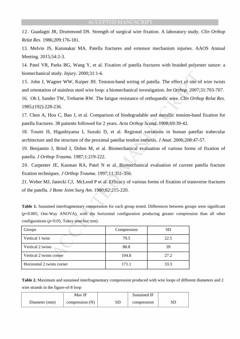
Table 1. Sustained interfragmentary compression for each group tested. Differences between groups were significant
(p=0.005, One-Way ANOVA), with the horizontal configuration producing greater compression than all other
configurations (p<0.05, Tukey post-hoc test).
Groups Compression SD
Vertical 1 twist 79.5 22.5
Vertical 2 twists 88.8 39
Vertical 2 twists corner 104.8 27.2
Horizontal 2 twists corner 171.1 33.3
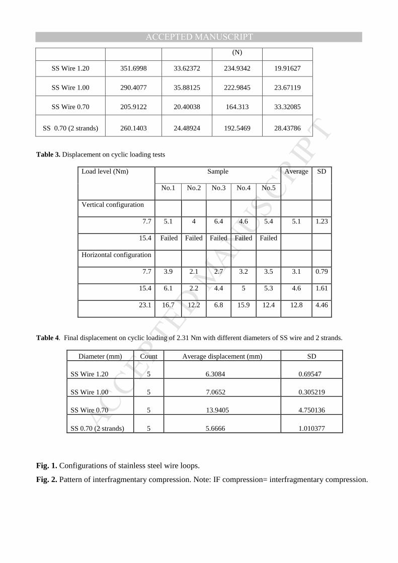
Table 2. Maximum and sustained interfragmentary compression produced with wire loops of different diameters and 2
wire strands in the figure-of-8 loop
Diameter (mm)
Max IF
compression (N) SD
Sustained IF
compression SD
MANUSCRIP
T
ACCEPTED
ACCEPTED MANUSCRIPT(N)
SS Wire 1.20 351.6998 33.62372 234.9342 19.91627
SS Wire 1.00 290.4077 35.88125 222.9845 23.67119
SS Wire 0.70 205.9122 20.40038 164.313 33.32085
SS 0.70 (2 strands) 260.1403 24.48924 192.5469 28.43786
Table 3. Displacement on cyclic loading tests
Load level (Nm) Sample
Average SD
No.1 No.2 No.3 No.4 No.5
Vertical configuration
7.7 5.1 4 6.4 4.6 5.4 5.1 1.23
15.4 Failed Failed Failed Failed Failed
Horizontal configuration
7.7 3.9 2.1 2.7 3.2 3.5 3.1 0.79
15.4 6.1 2.2 4.4 5 5.3 4.6 1.61
23.1 16.7 12.2 6.8 15.9 12.4 12.8 4.46
Table 4. Final displacement on cyclic loading of 2.31 Nm with different diameters of SS wire and 2 strands.
Diameter (mm) Count Average displacement (mm) SD
SS Wire 1.20 5 6.3084 0.69547
SS Wire 1.00 5 7.0652 0.305219
SS Wire 0.70 5 13.9405 4.750136
SS 0.70 (2 strands) 5 5.6666 1.010377
Fig. 1. Configurations of stainless steel wire loops.
Fig. 2. Pattern of interfragmentary compression. Note: IF compression= interfragmentary compression.

MANUSCRIP
T
ACCEPTED
ACCEPTED MANUSCRIPT

MANUSCRIP
T
ACCEPTED
ACCEPTED MANUSCRIPT