Embed Size (px)
Citation preview
DOI: http://dx.doi.org/10.1590/1980-5373-MR-2015-0596Materials Research. 2016; 19(3): 588-593 © 2016
*e-mail: [email protected]
1. IntroductionDespite the variety of sizes and shapes of bone plates and
screws, the choice of implants depends on various factors such as fracture site, fracture type, bone quality, strength and stiffness required, cost and availability1-3. The traditional reconstruction plates are considered to be less stiff and designed with V-shaped grooves between the screw holes, to allow contour in three directions3-5. This allows a better fit on more complex bony contours, or bones with irregular anatomic shapes, but makes it weaker compared with dynamic compression plates of equivalent size3,4,6.
Several mechanical and biological advantages have been attributed to the locking screw–plate, including axial and angular stability due to its locking mechanism between plate and screw, preservation of the periosteal blood supply, reduced requirement for anatomical plate contouring, and possibility the system’s elasticity to stimulate bone healing1,2,7-10. These advantages have stimulated the modification or conversion of various traditional bone plates into locked systems, including reconstruction plates, by changing especially the screw-hole geometry.
However, there are some details that can influence the stability and resistance of the system, including the
material used to manufacture the plate and screws, locking screw design, number and position of the screws, and type of mechanism for locking the screw into the plate7,8,10-14. The locking mechanisms include screw head with threads that match with threads into the plate hole or into adapter, and threaded locknut or bushing into which the screw head is locked10,14.
On the other hand, the importance of the screw length - monocortical or bicortical - as a determining factor in fixation stability differs between a conventional plate and a locking plate7,10. Monocortical locking head screw has pullout resistance approximately 70% of the bicortical locking head screw, and pullout resistance similar to a conventional bicortical screw of comparable diameter15,16. Because locked screws are under minimal tensile preload, the inclusion of the opposite bone cortex to obtain maximum purchase is apparently not critical10,17,18. The stabilising effect of the second cortex is substituted by the locking system18. However, this may vary depending on the fracture site and bone quality1,8,10. In osteoporotic bone, the use of monocortical screws may not be sufficient to maintain stability, since the working length of the screw is dependent on the thickness of the bone cortex7,8,12. In addition, the magnitude of the rotational forces
Biomechanical Analysis of Locking Reconstruction Plate Using Mono- or Bicortical Screws
Rogerio Rodrigues Santosa; Sheila Canevese Rahala*; Camilo Mesquita Netob,
Celso Roberto Ribeiroc, Edson Antonio Capello Sousad, Cesar Renato Foschinid,
Felipe Stefan Agostinhoa, Luciane dos Reis Mesquitaa
aDepartment of Veterinary Surgery and Anesthesiology, School of Veterinary Medicine and Animal Science, Universidade Estadual Paulista – UNESP, Botucatu, SP, Brazil
bLaboratório de Ensaios Mecânicos e Metalográficos – LEMM, IPAC, Jaú, SP, BrazilcSGS Labmat, Distrito Industrial Uninorte, Piracicaba, SP, Brazil
dSchool of Engineering, Universidade Estadual Paulista – UNESP, Bauru, SP, Brazil
Received: October 3, 2015; Revised: January 14, 2016; Accepted: March 9, 2016
This experimental in vitro study evaluated the influence of screw length on the mechanical properties of a locking reconstruction plate designed with locking rings inserted into plate holes. Synthetic bone cylinders with 10 mm fracture gap and seven-hole locking reconstruction plates were used. Two groups of bone-plate constructs were assembled: Group 1 – three monocortical screws on each fracture side, Group 2 - three bicortical screws on each fracture side. In each group nine bone-plate constructs were tested until failure, three each in bending, compression and torsion. In each group, 21 bone-plate constructs were tested for failure in fatigue testing, seven each for bending, compression and torsion. In all static testing no significant differences were found between G1 and G2, except ultimate moment in torsion test (G2>G1; P=0.008). Statistical analysis revealed significant differences between groups in axial compression fatigue testing (G1>G2; P<0.05) and four-point bending fatigue testing (G1<G2; P<0.05) in maximum load, minimum load, maximum moment, and minimum moment. In conclusion, screw length can affect the mechanical properties of locking reconstruction plate. Compared to bicortical screws, monocortical screws were less resistant to bending than axial compression. This must be considered when choosing implant, particularly in fractures under high axial loads.
Keywords: Fracture, bone-plate, Mechanical study

Biomechanical Analysis of Locking Reconstruction Plate Using Mono- or Bicortical Screws2016; 19(3) 589
involved to the fractured bone is another reason that should be considered to avoid monocortical screws16.
Therefore, this study aimed to evaluate the influence of screw length, monocortical or bicortical, on the biomechanical properties of a locking reconstruction plate designed with locking rings inserted into the plate holes. The hypothesis was that the bone-plate constructs would acquire more resistance by using bicortical screws.
2. Material and Methods2.1. Design of the experimental in vitro study
The involved laboratories and testing machines are according to ISO 17025: 2005. Therefore, calibration of the equipment and traceability are ensured. The load cells used in the equipment are calibrated annually, according to ISO 17025. The precision is more than 1% in the evaluated points.
Sixty synthetic bone cylinders constituted of polyurethane (Nacional Ossos; Jaú, Brazil) (length = 170 mm; outer diameter = 24 mm; cortical thickness = 2.5 mm (69 shore D [Shore Durometer; Hardness test]); cancellous thickness = 5 mm (38 shore D) and 60 seven-hole 3.5 mm locking reconstruction plates (Biomecânica Indústria e Comércio de Produtos Ortopédicos Ltda.; Jaú, Brazil) (14.5 cm long, 10 mm wide, 3.0 mm thick) composed of stainless steel (standard of ASTM F139) were used for mechanical testing (Figure 1). The locking rings of this plate allow the screws to be positioned and locked obliquely, if necessary. The ring was designed with an internal thread to accept the head screw and outside with a spherical surface to connect to the plate.
Each bone cylinder was cut in half to simulate a 10 mm fracture gap. Two groups of bone-plate constructs were assembled: Group 1 – three 3.5 mm monocortical (14 mm long) on each side of the fracture, Group 2 – three 3.5 mm bicortical screws (30 mm long) (Biomecânica Indústria e Comércio de Produtos Ortopédicos Ltda.; Jaú, Brazil) on each side of the fracture. The area of the fracture gap was maintained without a screw.
2.2. Preparation of bone-plate constructsEach portion of bone cylinder was fixed in a bench vise
and the plate was centered over the 10 mm fracture gap. The locked holes were drilled with a 2.5–mm drill bit and a specific drill guide (2.8mm) positioned into the locking
ring at 90º to the long axis of the cylinder. In Group 1 monocortical perforations were made and the six locked self-tapping 3.5 mm cortical screws, 14 mm long, were placed with the head locked in the locking rings (Figure 2a). In Group 2 bicortical perforations were made and the six locked self-tapping 3.5 mm cortical screws, 30 mm long, were placed with the head locked in the locking rings (Figure 2b). All screws were tightened with a torque wrench Model TRNA 20PA (Tork Ferramentas Ltda.; São Leopoldo, Brazil) using a same final torque of 2 Nm. No gap was induced between the plate and the bone cylinders.
2.3. Static testingThe tests were based on the standard of ASTM F382
(Standard Specification and Test Method for Metallic Bone Plates; West Conshohocken, PA, 2014). Nine bone-plate constructs in Group 1 and nine bone-plate in Group 2 were tested until failure, three each in compression, bending, and torsion. All tests were accomplished at room temperature (22-23ºC) utilizing an EMIC universal testing machine (DL-10000; São José dos Pinhais, Brazil) with maximum load capacity 100 kN, speed range of 5 mm/min, and supplied with the software TESC from EMIC (version 3.04). Failure (endpoint) was determined as the permanent deformation of the plate or the en bloc pullout of the screws in the bone cylinder with or without breakage of the bone cylinder. For axial compression test, a load cell of 1961N capacity was used. The loading rate was 5 mm/min with load support of 10 mm radius. The fixation supports (10 mm radius) were connected to testing machine by threading. The distance between these supports was 190 mm. The 4-point bending test was performed with the reconstruction plate on the tension side. The bone-plate construct was constrained by two support rollers positioned more externally and loaded by two load applicator rollers. A distance of 100 mm separated the central load applicator rollers, whereas a 150 mm distance separated the support rollers. The rollers had 10 mm diameter. A load cell capacity of 9807N with load rate of 5 mm/min was utilized. For the torsional test, the bone cylinders were connected to the testing machine
Figure 1. Seven-hole 3.5 mm locking reconstruction plate designed with locking rings inserted into the plate holes (a). Observe the locking ring that was removed of the bone plate hole (b).
Figure 2. Plates assembled according to length of the screws, showed by radiographic depictions: (a) Group 1 – three monocortical screws on each fracture side, (b) Group 2 - three bicortical screws on each fracture side.
Santos et al.590 Materials Research
using clamp chucks, with one end fixed and the other end attached to a mobile crosshead, employing a 490N load cell capacity and 200 mm/min load rate. The rotation speed was calculated in 0.4RPM. The torsional loading apparatus has a crown and chain. The lever arm system maintained constant load application avoiding torque variation during the testing. The lever arm was 87.15 mm and the gage length 110 mm.
2.4. Fatigue testingFor each group, 21 bone-plate constructs were tested for
failure in fatigue testing, seven each in bending, compression, and torsion. The applied loads for fatigue testing were started according to reference loads (Tables 4 and 5). The load obtained in fatigue testing does not exceed 10% of the failure load. Fatigue failure was established as plate deformation, or a pullout of the screws in the bone cylinder, or bone cylinder breakage. Tests were abandoned after 1,000,000 cycles if the construct had not already failed. All tests were carried out at room temperature (22-23ºC).
The axial compression test was performed using a LEMM testing machine (Laboratório de Ensaios Mecânicos e Metalográficos; Jaú, Brazil) with 5 kN capacity and load cell of 490N. Cyclical loads were applied under load control with load ratio (ratio of the maximum load to the minimum load) of 0.1 and frequency of 5 Hz. The reference loads (maximum loads) were 257.67N and 265N, respectively, for groups 1 and 2. The minimum load applied to the sinusoid was 10% of the maximum load. The maximum and minimum moments in axial compression test indicated the reaction of the structure to external force causing the element to bend. The moment was calculated using the equation: M = Pxl, where: M = moment; P = proof load (N); I = distance between application point of the axial force (middle of bone cylinder) up to half of bone plate thickness (mm).
The 4-point bending test was accomplished using a LEMM testing machine (Laboratório de Ensaios Mecânicos
e Metalográficos; Jaú, Brazil) with 20 kN capacity and 981N load cell. Cyclical loads were applied under load control with load ratio of 0.1 and frequency of 5 Hz. The reference loads (maximum loads) were 744.33N and 746.67N, respectively, for groups 1 and 2. The torsion test was accomplished using a testing machine (ElectroPuls E10000; Instron, Norwood, Canada) with 100Nm capacity and 25Nm load cell. The respective reference loads (maximum loads) were 4.33Nm and 6.6Nm for groups 1 and 2, with frequency of 1 Hz. The fatigue testing evaluated loads and moments, and number of cycles at which the failure occurred, or run out. The maximum and minimum values were used to adjust the fatigue sinusoid.
2.5. Statistical analysisStudent’s t Test for Independent Samples was used to
evaluate the data from static and fatigue mechanical testing. The non-parametric Mann-Whitney’s test was employed to evaluate the number of cycles to failure in fatigue testing. Differences were considered significant at p<0.05.
3. Results3.1. Static testing
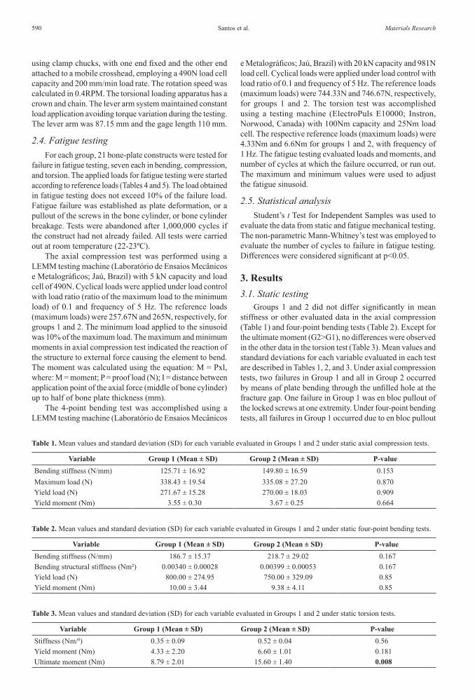
Groups 1 and 2 did not differ significantly in mean stiffness or other evaluated data in the axial compression (Table 1) and four-point bending tests (Table 2). Except for the ultimate moment (G2>G1), no differences were observed in the other data in the torsion test (Table 3). Mean values and standard deviations for each variable evaluated in each test are described in Tables 1, 2, and 3. Under axial compression tests, two failures in Group 1 and all in Group 2 occurred by means of plate bending through the unfilled hole at the fracture gap. One failure in Group 1 was en bloc pullout of the locked screws at one extremity. Under four-point bending tests, all failures in Group 1 occurred due to en bloc pullout
Table 3. Mean values and standard deviation (SD) for each variable evaluated in Groups 1 and 2 under static torsion tests.
Variable Group 1 (Mean ± SD) Group 2 (Mean ± SD) P-valueStiffness (Nm/0) 0.35 ± 0.09 0.52 ± 0.04 0.56Yield moment (Nm) 4.33 ± 2.20 6.60 ± 1.01 0.181Ultimate moment (Nm) 8.79 ± 2.01 15.60 ± 1.40 0.008
Table 1. Mean values and standard deviation (SD) for each variable evaluated in Groups 1 and 2 under static axial compression tests.
Variable Group 1 (Mean ± SD) Group 2 (Mean ± SD) P-valueBending stiffness (N/mm) 125.71 ± 16.92 149.80 ± 16.59 0.153Maximum load (N) 338.43 ± 19.54 335.08 ± 27.20 0.870Yield load (N) 271.67 ± 15.28 270.00 ± 18.03 0.909Yield moment (Nm) 3.55 ± 0.30 3.67 ± 0.25 0.664
Table 2. Mean values and standard deviation (SD) for each variable evaluated in Groups 1 and 2 under static four-point bending tests.
Variable Group 1 (Mean ± SD) Group 2 (Mean ± SD) P-valueBending stiffness (N/mm) 186.7 ± 15.37 218.7 ± 29.02 0.167Bending structural stiffness (Nm²) 0.00340 ± 0.00028 0.00399 ± 0.00053 0.167Yield load (N) 800.00 ± 274.95 750.00 ± 329.09 0.85Yield moment (Nm) 10.00 ± 3.44 9.38 ± 4.11 0.85

Biomechanical Analysis of Locking Reconstruction Plate Using Mono- or Bicortical Screws2016; 19(3) 591
of the locked screws at one extremity, but two also presented breakage of the bone cylinder. All failures in Group 2 were attributable to plate bending through the unfilled hole at the fracture gap, while one also presented breakage of the bone cylinder. Under torsion tests, all failures in Group 1 occurred due to en bloc pullout of the locked screws at one extremity, but one also showed bone-cylinder breakage. In Group 2, all failures occurred on account of bone-cylinder breakage, but one also presented en bloc pullout of the locked screws.
3.2. Fatigue testingAxial compression fatigue tests showed significant
intergroup differences in all variables (G1>G2) (Table 4). Failure occurred prior to 1,000,000 cycles in two bone-plate constructs from Group 1 and two from Group 2. In both groups the failures occurred via plate bending through the unfilled hole at the fracture gap. Four-point bending fatigue tests showed significant intergroup differences in all variables (G1<G2) (Table 5). Failure occurred before 1,000,000 cycles in three bone-plate constructs from Group 1 and four from Group 2. In Group 1, one of the failures was due to the plate bending through the unfilled hole at the fracture gap, one because of the breakage of the bone cylinder, and one due to en bloc pullout of the locked screws at one extremity. All failures in Group 2 occurred due to bone-cylinder breakage. The torsion test did not reveal any significant differences in mean torque (Nm) between Group 1 (Mean of 0.88 ± SD 0.71) and Group 2 (Mean of 2.9 ± SD 2.11) (P value = 0.068). Failure occurred prior to 1,000,000 cycles, except for one of the bone-plate constructs in each group. All failures occurred due to bone-cylinder breakage at the screw area. The number of cycles to failure (median) in all fatigue testing did not differ significantly between groups 1 and 2.
4. DiscussionBiomechanical studies with locking reconstruction
plates for human patients have been performed to evaluate specific fractures, including acetabulum15,17, clavicle4, distal humerus19-21 and mandible22, mainly to compare traditional plates with locking plates. In small animals, biomechanical evaluation was also performed on acetabular fractures of
canine cadavers for the same purpose23. However, there are unresolved questions in relation to the influence of screw length on the locking reconstruction plate that were investigated in the present study.
In all static testing no significant differences were found between the monocortical (G1) and bicortical (G2) bone-plate constructs, except for the ultimate moment in the torsion test (G2>G1). On the other hand, in the axial compression fatigue test, the bone-plate constructs using monocortical screws demonstrated better fatigue performance (loads and moments) than those with bicortical screws, whereas the opposite occurred in four-point bending fatigue. On the other hand, a biomechanical study performed in a simulated gap fracture model with canine cadaveric tibia reported that the constructs using locking compression plate (combi-holes) with bicortical screws were stiffer than monocortical constructs in torsion, but found no differences between screw constructs in four-point bending24. However, differences in bone plate types, distribution of the screws along the plate and bone models should be considered. In the present study all plate holes were filled except at the fracture gap, but in the study reported above the screws were positioned only in the most proximal and most distal portions of the plate as used in a minimally invasive percutaneous osteosynthesis24.
Cortical bone thickness is important for determining the adequacy of the working length of monocortical screws in a locked construction7,12. If cortical bone is of good quality, the pullout strength of a monocortical screw equals approximately 60% the pullout force of a conventional bicortical screw25. However, at least three cortices should be included on each side of the fracture, in each main fracture fragment8,12,26. Since the bone model used in this study is synthetic and non-osteoporotic, the cortical thickness did not influence the comparative evaluation between groups, with the differences being related to the forces involved.
Moreover, the monocortical fixation may be insufficient in metaphyseal bone with a minimal cortex, or in osteopenic bone, especially in bones where mainly torsional load predominates, such as the humerus1,7. This limitation is due to decreased working length of screw in osteoporotic bone, or the screw length in contact with the bone7,12. For example, in a study of synthetic ulna to simulate osteoporotic cortex, the
Table 4. Mean values and standard deviation (SD) for each variable evaluated in Groups 1 and 2 under fatigue axial compression testing.
Variable Group 1 (Mean ± SD) Group 2 (Mean ± SD) P-valueReference load (%) 64.28 ± 12.72 44.28 ± 9.75 0.006Maximum compression load (N) 165.63 ± 32.76 117.3 ± 25.84 0.01Minimum compression load (N) 16.56 ± 3.28 11.72 ± 2.58 0.01Maximum moment (Nm) 1.12 ± 0.22 0.79 ± 0.17 0.009Minimum moment (Nm) 0.11 ± 0.02 0.07 ± 0.01 0.006
Table 5. Mean values and standard deviation (SD) for each variable evaluated in Groups 1 and 2 under fatigue four-point bending testing.
Variable Group 1 (Mean ± SD) Group 2 (Mean ± SD) P-valueReference load (%) 44.28 ± 9.75 58.57 ± 8.99 0.015Maximum bending load (N) 329.6 ± 72.63 437.31 ± 67.17 0.014Minimum bending load (N) 32.96 ± 7.26 43.73 ± 6.71 0.014Maximum moment (Nm) 4.11 ± 0.9 5.46 ± 0.83 0.014Minimum moment (Nm) 0.41 ± 0.09 0.54 ± 0.08 0.014

Santos et al.592 Materials Research
constructs fixed by locking compression plate (combi-holes) with bicortical locked screws had less displacement after cyclic axial loading, and required a greater number of cycles to failure in cycling bending than the constructs with monocortical locked screws27. In addition, another study of an osteoporotic femoral diaphysis model found that unicortical locking plate constructs remained weaker than bicortical locking plate constructs in torsion28. Thus, the results obtained in the present study are only applicable in bones whose density is not compromised, since cortical thickness can alter the mechanical behavior of the constructs.
The ultimate moment had higher value in the Group 2 (bicortical) in static torsion testing, but in torsion fatigue testing no significant intergroup differences were found despite the higher values observed in Group 2. Also, in a study using locking compression plate (combi-holes) fixed in radius sawbone in different configurations, the locked monocortical constructs under torsional loads were the weakest when compared with locked hybrid constructs in which locked bicortical screws or unlocked bicortical screws had been placed on either end of the constructs29. Therefore, in fractures subject to high torsional forces, the use of locking monocortical screws can promote lower resistance depending on the bone-plate construct and implant type.
The better fatigue performance (loads and moments) of the bicortical bone-plate constructs in four-point bending fatigue in the present study is probably associated with the longer working length of bicortical screws compared to monocortical screws, and consequent higher resistance to torque12, as well as load sharing between the near and far cortices.
Cyclic loading provides important information about dynamic failure of the bone-plate construct. Several studies of locked plates have evaluated whether bone-plate constructs are able to resist cyclic loading within physiological limits of cycles and loads of the species under evaluation17,30-33. Despite the lack of significant intergroup differences in the same test, the lower number of cycles to failure occurred in torsion as compared to axial compression and four and four-point bending tests. This suggests that in both mono- and bicortical bone-plate constructs, the torsional fatigue failed earlier than the others.
The number of bone-plate constructs that resisted until 1,000,000 cycles (axial compression = 5, four-point bending = 4) was higher than that of another study that used an S.P.S. Free-Block plate (axial compression = 2, four-point bending = 3) with four monocortical locked screws positioned at 90º to the long axis of the cylinder and two traditional bicortical screws in same synthetic bone model34. Probably the locking reconstruction plate allowed greater flexibility than the hybrid construct, since the failures of the locking reconstruction plate, especially in axial compression, were due to plate bending through the unfilled hole at the fracture gap while the hybrid construct failure was attributable to breakage of the plate. As the reconstruction plates are designed to be easier to contour, they consequently have a relatively low bending stiffness4.
An elucidation of the role of each force in bone-plate construct resistance, as performed in the present study, helps to determine whether the plate is compatible with the fracture type and involved loads. This is especially important in small animals since the locking reconstruction plates have been used for treating various orthopedic conditions, including humeral condylar fractures35,36, panarthrodesis of the tarsus37, vertebral instability37, as well as for temporary stabilization in traumatic shoulder dislocation38, and for treating fractures of long bones such as the humerus, radius/ulna, femur and tibia39.
One of the limitations of the present study was that the influence of the number of screws on bone-plate construct was not assessed. In general, an overly stiff construct should be avoided in locking plates, because a lack of motion at the fracture site may prevent bone healing10,40,41.
However, from the present study, it may be concluded that the screw length can affect the mechanical properties of locking reconstruction plate with locking rings inserted into the plate holes. Compared to bicortical screws, the monocortical screws were less resistant to bending than axial compression. This must be considered when choosing the implant, particularly in fractures under high axial loads.
AcknowledgementsThe authors are grateful to CNPq and Fapesp.
References1. Egol KA, Kubiak EN, Fulkerson E, Kummer FJ, Koval KJ.
Biomechanics of locked plates and screws. Journal of Orthopaedic Trauma. 2004;18(8):488-493.
2. Chao P, Lewis DD, Kowaleski MP, Pozzi A. Biomechanical concepts applicable to minimally invasive fracture repair in small animals. Veterinary Clinics of North America, Small Animal Practice. 2012;42(5):853–872. doi:10.1016/j.cvsm.2012.07.007
3. Johnston SA, von Pfeil DJ, Déjardin LM, Weh M, Roe S. Internal fracture fixation. In: Tobias KM, Johnston S. Veterinary Surgery: Small Animal. St. Louis: Elsevier Saunders; 2012. p. 576-607.
4. Robertson C, Celestre P, Mahar A, Schwartz A. Reconstruction plates for stabilization of mid-shaft clavicle fractures: Differences between nonlocked and locked plates in two different positions. Journal of Shoulder and Elbow Surgery. 2009;18(2):204-209.
5. Johnson AL. Fundamentals of orthopedic surgery and fracture management. In: Fossum TW. Small Animal Surgery. 4th ed. St. Louis: Elsevier Mosby; 2013. p. 1086-1092.
6. Piermattei DL, Flo GL and DeCamp CE. Bone plates. In: Brinker WO, DeCamp CE. Brinker, Piermattei, and Flo’s Handbook of Small Animal Orthopedics and Fracture Repair. 4th ed. Philadelphia: Saunders; 2006. p. 125–142.
7. Gautier E, Sommer C. Guidelines for the clinical application of the LCP. Injury. 2003;34 Suppl 2:B63–B76.
8. Wagner M. General principles for the clinical use of the LCP. Injury. 2003;34 Suppl 2:B31-B42.
9. Szypryt P, Forward D. The use and abuse of locking plates. Orthopaedics and Trauma. 2009; 23(4):281-290. doi:10.1016/j.mporth.2009.07.002
10. Cronier P, Pietu G, Dujardin C, Bigorre N, Ducellier F, Gerard R. The concept of locking plates. Orthopaedics & Traumatology:

Biomechanical Analysis of Locking Reconstruction Plate Using Mono- or Bicortical Screws2016; 19(3) 593
Surgery & Research. 2010;96 (Suppl 4): S17-S36. doi:10.1016/j.otsr.2010.03.008
11. Stoffel K, Dieter U, Stachowiak G, Gächter A, Kuster MS. Biomechanical testing of the LCP- how can stability in locked internal fixator be controlled? Injury. 2003;34 Suppl 2: SB11-SB19.
12. Miller DL, Goswami T. A review of locking compression plate biomechanics and their advantages as internal fixators in fracture healing. Clinical Biomechanics. 2007;22(10):1049-1062.
13. Boudreau B, Benamou J, von Pfeil DJ, Guillou RP, Beckett C, Déjardin LM. Effect of screw insertion torque on mechanical properties of four locking systems. Veterinary Surgery. 2013; 42(5):535–543. doi: 10.1111/j.1532-950X.2013.12023.x.
14. Arthurs G. Advances in internal fixation locking plates. In Practice. 2015;37:13-22.
15. Mehin R, Jones B, Zhu Q, Broekhuyse H. A biomechanical study of conventional acetabular internal fracture fixation versus locking plate fixation. Canadian Journal of Surgery. 2009; 52(3):221-228.
16. Smith WR, Ziran BH, Anglen JO, Stahel PF. Locking plates: tips and tricks. Journal of Bone & Joint Surgery. 2007;89A:2298–2307.
17. Zhang Y, Tang Y, Wang P, Zhao X, Xu S, Zhang C. Biomechanical comparison of different stabilization constructs for unstable posterior wall fractures of acetabulum. A cadaveric study. Plos One. 2013;8(12):e82993. doi: 10.1371/journal.pone.0082993.
18. Perren SM. Evolution of the internal fixation of long bone fractures. The scientifgic basis of biological internal fixation: choosing a new balance between stability and biology. Journal of Bone & Joint Surgery Br. 2002; 84(8):1093–1110.
19. Korner J, Diederichs G, Arzdorf M, Lill H, Josten C, Schneider E, et al. A biomechanical evaluation of methods of distal humerus fracture fixation using locking compression plates versus conventional reconstruction plates. Journal of Orthopaedic Trauma. 2004;18:286–93.
20. Tejwani NC, Murthy A, Park J, McLaurin TM, Egol KA, Kummer FJ. Fixation of extra-articular distal humerus fractures using one locking plate versus two reconstruction plates: a laboratory study. Journal of Trauma. 2009;66(3):795-799.
21. Caravaggi P, Laratta JL, Yoon RS, DeBiasio J, Ingargiola M, Frank MA, et al. Internal fixation of the distal humerus: a comprehensive biomechanical study evaluating current fixation techniques. Journal of Orthopaedic Trauma. 2014;28:222-226.
22. Haug RH, Street CC, Goltz M. Does plate adaptation affect stability? A biomechanical comparison of locking and nonlocking plate. Journal of Oral and Maxillofacial Surgery. 2002;60(11):1319-1326.
23. Amato NS, Richards A, Knight TA, Spector D, Boudrieau RJ, Belkoff S. Ex vivo biomechanical comparison of the 2.4 mm uniLOCK reconstruction plate using 2.4 mm locking versus standard screws for fixation of acetabular osteotomy in dogs. Veterinary Surgery. 2008;37(8):741-748.
24. Demner D, Garcia TC, Serdy MG, Hayashi K, Nir BA, Stover SM. Biomechanical comparison of mono- and bicortical screws in an experimentally induced gap fracture. Veterinary and Comparative Orthopaedics and Traumatology. 2014;27(6):422-429. doi: 10.3415/VCOT-14-03-0040
25. Haidukewych GH. Innovations in locking plate technology. Journal of the American Academy of Orthopedic Surgeons. 2004;12(4):205-212
26. Schütz M, Südkamp NP. Revolution in plate osteosynthesis: new internal fixator systems. Journal of Orthopaedic Science. 2003;8(2):252-258.
27. Fulkerson E, Egol KA, Kubiak EN, Liporace F, Kummer FJ, Koval KJ. Fixation of diaphyseal fractures with a segmental
defect: a biomechanical comparison of locked and conventional plating techniques. Journal of Trauma. 2006;60(4):830-835.
28. Fitzpatrick DC, Doornink J, Madey SM, Bottlang M. Relative stability of conventional and locked plating fixation in a model of the osteoporotic femoral diaphysis. Clinical Biomechanics. 2009;24:203-209.
29. Roberts JW, Grindel SI, Rebholz B, Wang M. Biomechanical evaluation of locking plate radial shaft fixation: unicortical locking fixation versus mixed bicortical and unicortical fixation in a sawbone model. Journal of Hand Surgery American. 2007;32(7):971-975.
30. Goh CS, Santoni BG, Puttlitz CM, Palmer RH. Comparison of the mechanical behaviors of semicontoured, locking plate–rod fixation and anatomically contoured, conventional plate–rod fixation applied to experimentally induced gap fractures in canine femora. American Journal of Veterinary Research. 2009;70(1):23–29. doi: 10.2460/ajvr.70.1.23.
31. Mehling I, Schmidt-Horlohé K, Müller LP, Sternstein W, Korner J, Rommens PM. Locking reconstruction double plating of distal humeral fractures: how many screws in the distal ulnar column segment in A3 fracture provide superior stability? Journal of Orthopaedic Trauma. 2009;23(8):581-587. doi: 10.1097/BOT.0b013e3181a87725
32. Chao P, Conrad BP, Lewis DD, Horodyski M, Pozzi A. Effect of plate working length on plate stiffness and cyclic fatigue life in a cadaveric femoral fracture gap model stabilized with a 12-hole 2.4 mm locking compression plate. BMC Veterinary Research. 2013;9:125. doi: 10.1186/1746-6148-9-125.
33. Delisser PJ, McCombe GP, Trask RS, Etches JA, German AJ, Holden SL, et al. Ex vivo evaluation of the biomechanical effect of varying monocortical screw numbers on a plate-rod canine femoral gap model. Veterinary and Comparative Orthopaedics and Traumatology. 2013;26:177-185.
34. Merino MK, Rahal SC, Ribeiro CR, Padovani CR. The effect of locked screw angulation on the biomechanical properties of the S.P.S. Free-Block plate. Veterinary and Comparative Orthopaedics and Traumatology. 2013;26(2):117–122. doi: 10.3415/VCOT-12-03-0045
35. McCartney WT, MacDonald B, Comiskey DP, Garvan CB. Use of a plate and screws to repair lateral humeral condylar fractures in 10 dogs. International Journal of Applied Research in Veterinary Medicine. 2006;4:335-338.
36. McCartney WT, Comiskey DP, MacDonald B, Garvan CB. Fixation of humeral intercondylar fractures using a lateral plate in 14 dogs supported by finite element analysis of repair. Veterinary and Comparative Orthopaedics and Traumatology. 2007;20(4):285-290.
37. Keller MA, Voss K, Montavon PM. The ComPact Unilock 2.0/2.4 system and its clinical application in small animal orthopedics. Veterinary and Comparative Orthopaedics and Traumatology. 2005;18(2):83-93.
38. Post C, Guerrero T, Voss K, Montavon PM. Temporary transarticular stabilization with a locking plate for medial shoulder luxation in a dog. Veterinary and Comparative Orthopaedics and Traumatology. 2008;21(2):166-170.
39. Voss K, Kull MA, Haessig M, Montavon P. Repair of long-bone fractures in cats and small dogs with the Unilock mandible locking plate system. Veterinary and Comparative Orthopaedics and Traumatology. 2009;22(5):398-405.
40. Kubiak EN, Fulkerson E, Strauss E, Egol KA. The evolution of locked plates. Journal of Bone & Joint Surgery. 2006;88 Suppl 4:189-200.
41. Scolaro JA, Ahn J. Locked plating: indications and current concepts. University of Pennsylvania Orthopaedic Journal. 2011;21:18-22.