Embed Size (px)
Citation preview

Biodiesel Production through Ionic Liquid Catalysed
Esterification
Arevik Tadevosyan
Supervisors:
Professora Ana Queiroz
Professor António Ribeiro
Professor Paulo Brito
Professora Nelli Hovhannisyan
Bragança
July, 2017

i
Acknowledgments
First of all, I would like to thank my supervisors Ana Queiroz, António Ribeiro, Paulo Brito
for the kind and invaluable guidance throughout my work at the Polytechnic Institute of
Bragança, for indispensable advices and help for finished this thesis. I also would like to
thank to my supervisor Nelli Hovhannisyan from National Polytechnic University of
Armenia for her support.
For sure, this work would not be possible without International Credit Mobility (ICM)
Programme. It gave me all opportunities to get double diploma.
I would like to convey my special thanks to Paula Plasencia and Maria João Afonso, for their
help in the laboratory, for doing all experiments. And I would like to thank to Isabel Patrícia
Fernandes, for her help with FTIR analysis. Also i want to say thanks to Fernanda Fontana
Roman, my friend from Brazil. She was with me every day in laboratory.
My heartiest gratitude should goes to my loving family and all my friends for their numerous
help, and giving me courage and strength.
ii
Abstract
Biodiesel is an alternative fuel diesel that can be produced from vegetable oils and animal
fats. There is a recent growing interest in the development of alternative technologies to the
oil economy, based on renewable energy sources. A possible solution is a biofuel usable in
compression-ignition engines, produced from biomass rich in fats and oils. A wide range of
raw materials can be used in the production of biodiesel. Nevertheless, the use of sources that
do not compete with the food market like waste cooking oils, which usually feature high
levels of free fatty acids (FFA’s), can put problems in the process of production of biodiesel
through alkaline transesterification. These problems are partially overcome by the use of
catalysts, such as ionic liquids (IL’s) that also promote reactions of esterification of FFA’s to
biodiesel. Thus, the objective of this work consists in the study of the influence of IL's
application in the catalysis of: esterification reactions of organic acids to the corresponding
methyl esters.
In the first part of the work the influence, as catalysts, of several ionic liquids in the
esterification reaction of oleic acid was analyzed. The experimental conditions were as
follows: reaction time 6 hours, oleic acid / methanol molar ratio = 1/10 and temperature 90 °
C. The ionic liquids evaluated were as follows: 1-butyl-3-methylimidazolium hydrogen
sulfate ([BMIM][HSO4]), 1-butyl-3-methylimidazolium methanesulfonate
([BMIM][CH3SO3]), 1-butyl-3-methylimidazolium methylsulfate ([BMIM][CH3SO4]), 1-
metylimidazolium hydrogen sulfate ([MIM][HSO4]) and tributylmethylammonium
methylsulfate. The values obtained for the conversion of the oleic acid esterification reaction
showed that the ionic liquid [BMIM] [HSO4] would be one of the most promising catalysts.
In a second part of the work, the recovery of LI [BMIM] [HSO4] was studied and several
esterification reactions of oleic acid were carried out using a quantity of catalyst of 10 wt%,
15 wt% and 20 wt% relative to the mass of oleic acid. The experimental conditions were as
follows: reaction time 6 hours, oleic acid / methanol molar ratio = 1/10 and temperature 90 °
C. The reaction yield was found to be 76.6% to 10% IL, 83.3% to 15% IL and 84.8% to 20%
IL. These yields decreased to 58.2% (10% IL) with 4 cycles of recycling, 75.2% (15% IL)
with 5 cycles of recycling and 77.1% (20% IL) with 5 cycles of recycling. The results
obtained confirm that it is possible to reuse this IL in successive reactions of esterification
without great loss of yield and with this to significantly reduce the costs associated with the
purchase of these compounds that are quite expensive.

iii
Keywords: Biodiesel, Esterification, Ionic Liquids, Recovery

iv
Resumo
O biodiesel é um combustível alternativo que pode ser produzido a partir de óleos vegetais e
de gorduras animais. Atualmente existe um crescente interesse no desenvolvimento de
tecnologias alternativas à economia do petróleo baseadas em fontes de energia renováveis.
Uma possível solução é a utilização de um biocombustível em motores de compressão-
ignição, produzido a partir de biomassa rica em óleos e gorduras. Para a produção de
biodiesel pode ser usada uma ampla gama de matérias-primas. No entanto, o uso de fontes
que não competem com o mercado alimentar, como por exemplo os óleos alimentares usados,
que geralmente têm um elevado nível de ácidos gordos livres (AGL´s), pode trazer problemas
ao processo de produção de biodiesel através da transesterificação alcalina. Estes problemas
são parcialmente ultrapassados usando catalisadores, tais como os líquidos iónicos (LI´s), que
também promovem as reações de esterificação dos AGL´s a biodiesel.
Assim, o objetivo desta dissertação de mestrado consistiu no estudo da aplicação de líquidos
iónicos como catalisadores nas reações de esterificação de ácidos orgânicos aos
correspondentes ésteres metílicos.
Na primeira parte do trabalho analisou-se a influência, como catalisadores, de diversos
líquidos iónicos na reação de esterificação do ácido oleico. Os líquidos iónicos avaliados
foram os seguintes: 1-butyl-3-methylimidazolium hydrogen sulfate ([BMIM][HSO4]), 1-
butyl-3-methylimidazolium methanesulfonate ([BMIM][CH3SO3]), 1-butyl-3-
methylimidazolium methylsulfate ([BMIM][CH3SO4]), 1-metylimidazolium hydrogen sulfate
([MIM][HSO4]) and tributylmethylammonium methylsulfate. Os valores obtidos para a
conversão da reação de esterificação do ácido oleico mostraram que o líquido iónico
[BMIM][HSO4] seria um dos mais promissores como catalisador.
Numa segunda parte do trabalho procedeu-se ao estudo da recuperação do LI
[BMIM][HSO4], tendo-se realizado diversas reações de esterificação do ácido oleico usando
uma quantidade de catalisador de 10%, 15% e 20% (m/m) relativamente à massa de ácido
oleico. As condições experimentais foram as seguintes: tempo de reação 6 horas, razão molar
ácido oleico/metanol = 1/10 e temperatura 90 °C. Verificou-se que o rendimento da reação
foi de 76,6 % para 10% de LI, 83,3% para 15% de LI e 84,8% para 20% de LI. Estes
rendimentos diminuíram para 58,2% (10% de LI) com 4 atapas de reciclagem, 75,2% (15%
de LI) com 5 etapas de reciclagem e 77,1% (20% de LI) com 5 etapas de reciclagem. Os
resultados obtidos permitem confirmar que é possível reutilizar este LI em reações sucessivas

v
de esterificação sem grande perda de rendimento e com isso diminuir significativamente os
custos associados à compra destes compostos que são bastante caros.
Palavras-chave: Biodiesel, Esterificação, Líquidos Iónicos, Reutilização

vi
Համառոտագիր
Կենսադիզելն այլընտրանքային դիզելային վառելիք է, որն ստացվում է բուսական
յուղերից և կենդանական ճարպերից: Վերջին շրջանում աճում է
հետաքրքրությունն այլընտրանքային տեխնոլոգիաների` նավթային
տնտեսության, հիմականում վերականգնվող էներգիայի աղբյուրների նկատմամբ:
Հնարավոր լուծում է ներքին այրման շարժիչներում կենսավառելիքի
օգտագործումը, որն արտադրված է ճարպերով և յուղերով հարուստ
կենսազանգվածից: Կենսադիզելի արտադրության մեջ հնարավոր է օգտագործել
հումքի լայն ընտրանի: Օգտագործվող հումքի աղբյուրները չեն մասնակցում
պարենային շուկայի մրցակցությանը: Այդպիսիք են` խոհանոցային թափոններ
հանդիսացող յուղերը, որոնք հիմնականում բնորոշվում են խնդրահարույց ազատ
ճարպային թթուների (ԱՃԹ) մեծ պարունակությամբ: Այս խնդիրը մասամբ
հաղթահարվել է` օգտագործելով կատալիզատորներ, ինչպիսիք են իոնային
հեղուկները (ԻՀ), որոնք նույնպես նպաստում են կենսադիզելում ԱՃԹ-ի
եթերացմանը: Այսպիսով, այս աշխատանքի նպատակն է ուսումնասիրել իոնային
հեղուկ կատալիզատորների ազդեցությունը համապատասխան մեթիլեթերների
հետ օրգանական թթուների եթերացման ռեակցիաներում:
Աշխատանքի առաջին մասում հետազոտվել է մի քանի իոնային հեղուկների
ազդեցությունն օլեինաթթվի եթերացման ռեակցիայում: Փորձի պայմանները
հետևյալն են. ռեակցիայի ժամանակը ` 6 ժամ, օլեինաթթու / մեթանոլ մոլային
հարաբերակցությունը` 1/10, ջերմաստիճանը 90°C: Հետազոտվող իոնային
հեղուկները հետևյալն են. 1-բութիլ-3-մեթիլիմիդազոլիումի հիդրոսուլֆատ
([BMIM][HSO4]), 1-բութիլ-3-մեթիլիմիդազոլիումի մեթանսուլֆոնատ
([BMIM][CH3SO3]), 1-բութիլ-3-մեթիլիմիդազոլիումի մեթիլսուլֆատ
([BMIM][CH3SO4]), 1-մեթիլիմիդազոլիումի հիդրոսուլֆատ ([MIM][HSO4]) և
տրիբութիլմեթիլամոնիումի մեթիլսուլֆատ: Օլեինաթթվի եթերացման ռեակցիայի
արդյունքները ցույց տվեցին, որ [BMIM][HSO4] իոնային հեղուկն
ամենախոստումալից կատալիզատրներից մեկն է:

vii
Աշխատանքի երկրորդ մասում ուսումնասիրվել են [BMIM][HSO4] իոնային
հեղուկի վերականգնումը և օլեինաթթվի եթերացման մի քանի ռեակցիաներ,
որոնցում օգտագործված կատալիզատորի զանգվածը եղել է օլեինաթթվի
զանգվածի 10%, 15%, 20%-ը: Փորձի պայմանները հետևյալն են. ռեակցիայի
ժամանակը ` 6 ժամ, օլեինաթթու / մեթանոլ մոլային հարաբերակցությունը` 1/10,
ջերմաստիճանը 90°C: Ռեակցիայի ելքը կազմել է 76.6% ԻՀ-ի 10%-ի դեպքում, 83.3%
` ԻՀ-ի 15%-ի դեպքում և 84.8%` ԻՀ-ի 20%-ի դեպքում: Այս ելքերը նվազել են մինչև
58.2% (10% ԻՀ)` վերամշակման 4 ցիկլից հետո, 75.2% (15% ԻՀ)` վերամշակման 5
ցիկլից հետո, 77.1% (20% ԻՀ)` վերամշակման 5 ցիկլից հետո: Ստացված
արդյունքները հաստատում են, որ հնարավոր է այս ԻՀ-ի վերաօգտագործումը
եթերացման հաջորդական ռեակցիաներում` առանց ելքի մեծ կորստի, և
զգալիորեն նվազեցնել այդ, բավականին թանկ, միացությունների գնման հետ
կապված ծախսերը:
Առանցքային բառեր. կենսադիզել, եթերացում, իոնային հեղուկ, վերամշակում:

viii
Table of Contents
1 Introduction ........................................................................................................................ 1
1.1 Background and Motivation ........................................................................................ 3
1.2 Structure of the report ................................................................................................. 4
2 Biodiesel ............................................................................................................................. 5
2.1 Biodiesel as a renewable energy source ...................................................................... 5
2.2 Physicochemical properties ......................................................................................... 5
2.3 Benefits of biodiesel use ............................................................................................. 7
2.4 Advantages and disadvantages of biodiesel ................................................................ 8
2.5 Energy balance ............................................................................................................ 9
2.6 The biodiesel production and consumption in the world ............................................ 9
2.6.1 Biodiesel Consumption.......................................................................................... 10
2.6.2 Raw materials for Biodiesel production ................................................................ 11
2.7 Production of biodiesel.............................................................................................. 12
2.7.1 Esterification and Transesterification .................................................................... 14
3 Ionic liquids ...................................................................................................................... 17
3.1 Classification of ionic liquids .................................................................................... 18
3.2 Ionic liquid properties ............................................................................................... 20
3.3 The role of ionic liquids in transesterification reactions ........................................... 22
3.4 Ionic Liquids recovery .............................................................................................. 23
4 Experimental ..................................................................................................................... 26
4.1 Introduction ............................................................................................................... 26
4.2 Chemicals and Equipment ......................................................................................... 26
4.3 Biodiesel Production by Esterification Reaction ...................................................... 27
4.4 Recovery of ILs ......................................................................................................... 29
4.4.1 Biodiesel Acidity Measurements ........................................................................... 31
ix
4.5 Analysis of Fatty Acid Methyl Ester (FAME) Content by Gas Chromatography .... 32
4.5.1 Identification of FAMEs Compounds Methodology ............................................. 33
4.5.2 Characterization of Oleic Acid .............................................................................. 35
4.5.3 Determination of FAME Content .......................................................................... 35
4.6 Ionic Liquid Analysis with UV Spectrophotometer .................................................. 36
4.7 Ionic Liquid Analysis with Fourier Transform Infrared Spectroscopy (FTIR) ........ 37
5 Results and Discussion ..................................................................................................... 38
5.1 The Selection of the Ionic Liquid .............................................................................. 38
5.2 Internal Standard characterization ............................................................................. 40
5.2.1 Complete esterification of Oleic Acid using sulfuric acid .................................... 41
5.3 Characterization of biodiesel samples using different amounts of ionic liquid ........ 42
5.3.1 Ratio of Ionic Liquid to Oleic Acid of 10% .......................................................... 44
5.3.2 Ratio of Ionic Liquid to Oleic Acid of 15% .......................................................... 45
5.3.3 Ratio of Ionic Liquid to Oleic Acid of 20% .......................................................... 47
5.4 ILs analysis by UV-VIS ............................................................................................ 48
5.5 ILs analysis by FTIR ................................................................................................. 49
6. Conclusions and Future work .............................................................................................. 54
References ................................................................................................................................ 55
Appendix .................................................................................................................................. 60

v
List of Tables
Table 1. Biodiesel main properties [Biodiesel handling and use guide, 2016]. ........................ 6 Table 2. Comparison of biodiesel with petrodiesel. .................................................................. 8 Table 3. Summary of Energy Balance/Energy Life Cycle
[http://dartonrefuel.com/biodiesel.php/]. ............................................................................ 9 Table 4. Methods for biodiesel production [Pacini et al., 2014]. ............................................. 14 Table 5. Recent published studies using different oils and ionic liquids for biodiesel
production. Effect of reaction and time reaction on production yield .............................. 22 Table 6. Recent published studies involving ILs recovery for reactions of biodiesel
production, using different oils and ionic liquids ............................................................. 25 Table 7. Chemical formula, density and molecular weight of oleic acid and the 5 ionic
liquids. .............................................................................................................................. 27 Table 8. Identification of the retention time of all the 37 compounds of the Supelco FAME
Mix standard solution using the Supelcowax-10 column using the GC method presented
in section 4.4.2. ................................................................................................................. 34 Table 9. Biodiesel production yield using different ionic liquids in different time (10% IL) . 39 Table 10. Effect of quantity of [BMIM][HSO4] on production conversions .......................... 39 Table 11. Number of runs (recovery) ILs 10%, 15%, 20% and reaction conversions. ........... 43 Table 12. ILs mass after from recovery runs ........................................................................... 44 Table 13. Functional group of the components of original IL [Colthup et al., 2009] .............. 50 Table 14. Functional group of the components of IL 10% (REC4) [Colthup et al., 2009] ..... 51 Table 15. Functional groups of the components of IL 15% (REC5) [Colthup et al., 2009] .... 52 Table 16. Functional group of the components of IL 20% (REC5) [Colthup et al., 2009]. .... 53

vi
List of Figures
Figure 1. Biodiesel production in different countries, 2009-2010 [Johanson et al., 2012]. .... 10 Figure 2. EU-28 renewable energy in transport, by source (source: EUROSTAT, Öko-
Institut) [Renewable Energy Progress Report- 2017] ....................................................... 11 Figure 3. Production of biodiesel in Portugal 2006-2018 (Million litres) [Phillips et al., 2016].
.......................................................................................................................................... 11 Figure 4. Feedstock used for biodiesel production in the European Union and Portugal
[Castanheira et al., 2015]. ................................................................................................. 12 Figure 5. Biodiesel synthesis by esterification process from Free Fatty acid with alcohol
[Maria et al., 2011]. .......................................................................................................... 14 Figure 6. Basic technology of biodiesel esterification process. ............................................... 15 Figure 7. Biodiesel synthesis by transesterification process from vegetable oils with
methanol [Ullah et al., 2014]. ........................................................................................... 15 Figure 8. Basic technology of biodiesel transesterification process [www.bioethanol.ru-2016].
.......................................................................................................................................... 16 Figure 9. Chemical structure of ionic liquids [http://www.sigmaaldrich.com-2016]. ............. 18 Figure 10. Selected anions of phosphonium- and ammonium-based ILs [Stojanovic et al.,
2011]. ................................................................................................................................ 19 Figure 11. Structure of different ILs ........................................................................................ 19 Figure 12. Experimental setup for the esterification: 1) Heater 2) Reactor 3) Condenser. ..... 28 Figure 13. Tubes with the mixture after reaction: 1) Organic phase 2) Water phase. ............. 28 Figure 14. Separation Phases. .................................................................................................. 29 Figure 15. Vacuum oven. ......................................................................................................... 30 Figure 16. ILs samples before and after recovery. ................................................................... 30 Figure 17. The VARIAN CP-3800 gas chromatography system. ........................................... 32 Figure 18. GC chromatogram obtained for the Supelco 37 FAME standard mix using a
Supelcowax-10 column. ................................................................................................... 33 Figure 19. GC Chromatogram obtained for Supelco 37 Component FAME Mix on
Omegawax 250 Column (Supelco Bulletin 907). ............................................................. 33 Figure 20. VARIAN Cary 50 UV-Vis Spectrophotometer. ..................................................... 36 Figure 21. FTIR ABB MB300 spectrometer. .......................................................................... 37 Figure 22. A multiple reflection ATR system. ........................................................................ 38 Figure 23. Biodiesel which we got from this reaction ............................................................. 40
vii
Figure 24. GC chromatogram obtained for the methyl heptadecanoate solution (10 mg/mL).
Both figures represent the same chromatogram (right figure used to visual identify the
main peaks in baseline)..................................................................................................... 41 Figure 25. GC chromatogram obtained for the biodiesel sample obtained from esterification
using sulfuric acid and with the addition of the internal standard. ................................... 42 Figure 26. Reaction conversions dependency from amount catalyst and number of runs
(recovery) ILs 10%, 15%, 20%. ....................................................................................... 43 Figure 27. ILs mass (g) dependency from numbers of run (recovery) ILs 10%, 15%, 20%. .. 44 Figure 28. GC chromatograms obtained for the biodiesel samples obtained for 10% IL, from
esterification after 4 recovery steps (REC 10.1 to 10.4). ................................................. 45 Figure 29. GC chromatograms obtained for the biodiesel samples obtained for 15% IL, from
esterification after 4 recovery steps (REC 15.1 to 15.5). ................................................. 46 Figure 30. GC chromatograms obtained for the biodiesel samples obtained for 20% IL, from
esterification after 4 recovery steps (REC 20.1 to 20.5). ................................................. 47 Figure 31. UV-Vis spectrum obtained for original and the recovered ILs obtained for
different amount of ILs (10, 15 and 20%). ....................................................................... 48 Figure 32. Formula 1-Butyl-3-methylimidazolium hydrogen sulfate. ..................................... 49 Figure 33. FTIR spectrum obtained for original IL and methanol. ......................................... 49 Figure 34. FTIR spectrum obtained for original IL 10% (REC4). .......................................... 51 Figure 35. FTIR spectrum obtained for original IL 15% (REC5). .......................................... 52 Figure 36. FTIR spectrum obtained for original IL 20% (REC5). .......................................... 53

viii
List of abbreviations
FFA Free Fatty Acids
IL Ionic Liquid
FAME Fatty Acidy Methyl Ester
HVO Hydro treated Vegetable Oil
BTL Biomass to Liquid Fuel
DES Deep Eutectic Solvent
AC Activated Carbon
FID Flame Ionization Detector
GC Gas Chromatography
wt Weight
t Time
T Temperature
UV Ultra-Violet
SCCO2 Supercritical Carbon Dioxide
FTIR Fourier Transform Infrared Spectroscopy
IR Infrared
ART Attenuated Total Reflection

ix
List with the name materials
NOX Nitrogen Oxides
NaOH Sodium hydroxide
BF4– Tetrafluoroborate
PF6– Hexafluorophosphate
CH3CO2– Acetate
CF3CO2– Trifluoroacetate
NO3– Nitrate
[Al2Cl7]- heptachlorodialuminate
BASIL Biphasic Acid Scavenging Using Ionic Liquids
[Hnmm] OH 1-butyl-3-methyl morpholine hydroxide
MeOH Methanol
[C2MIM][TfO] 1-butyl-3-methylimidazolium trifluoromethanesulfanate
[C4MIM] [NTf2] 1-butyl-3-methylimidazolium
bis(trifluoromethylsulfonyl)imide
[C18MIM][NTf2] 1-octadecyl-3-methylimidazolium
bis(trifluoromethylsulfonyl)imide
[C16MIM][NTf2]), 1-Hexadecyl-3-methylimidazolium
bis(trifluoromethylsulfonyl)imide
[BMI][PF6]) 1-n-butyl-3-methylimidazolium hexafluorophosphate
[BMI][BF4] 1-n-butyl-3-methylimidazolium tetrafluoroborate
[BMIM][FeCl4] 1-butyl-3-methylimidazolium tetrachloroferrate
[HMIM]HSO4 1-hexyl-3-Methylimidazolium Hydrogen Sulfate
SiO2 Silica

x
Al2O3 Alumina
TiO2 Titanium dioxide
[BMIMHSO4] 1-Butyl-3-Methylimidazolium Hydrogen Sulfate
[PSPy][HSO4] N-propane-sulfonic acid pyridinium hydrogen sulfate
[NMP][HSO4] N-methyl-2-pyrrolidonium hydrogensulfate
[(CH2)4SO3HMIM] [CF3SO3] 1-(4-sulfobutyl)-3-methylimidazolium
trifluoromethanesulfonate
[(CH2)4SO3HMIM] [HSO4] 1-(4-sulfobutyl)-3-methylimidazolium hydrogen sulfate
KOH Potassium hydroxide
HCl Hydrochloric acid
He Helium
H2SO4 Sulfuric acid
[BMIM][MeSO4] 1-Butyl-3-methylimidazolium methyl sulfate
[MIM][HSO4] 1-Methylimidazolium hydrogen sulfate
1
1 Introduction
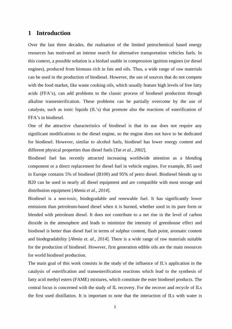
Over the last three decades, the realisation of the limited petrochemical based energy
resources has motivated an intense search for alternative transportation vehicles fuels. In
this context, a possible solution is a biofuel usable in compression ignition engines (or diesel
engines), produced from biomass rich in fats and oils. Thus, a wide range of raw materials
can be used in the production of biodiesel. However, the use of sources that do not compete
with the food market, like waste cooking oils, which usually feature high levels of free fatty
acids (FFA’s), can add problems to the classic process of biodiesel production through
alkaline transesterification. These problems can be partially overcome by the use of
catalysts, such as ionic liquids (IL’s) that promote also the reactions of esterification of
FFA’s in biodiesel.
One of the attractive characteristics of biodiesel is that its use does not require any
significant modifications to the diesel engine, so the engine does not have to be dedicated
for biodiesel. However, similar to alcohol fuels, biodiesel has lower energy content and
different physical properties than diesel fuels [Tat et al., 2002].
Biodiesel fuel has recently attracted increasing worldwide attention as a blending
component or a direct replacement for diesel fuel in vehicle engines. For example, B5 used
in Europe contains 5% of biodiesel (B100) and 95% of petro diesel. Biodiesel blends up to
B20 can be used in nearly all diesel equipment and are compatible with most storage and
distribution equipment [Ahmia et al., 2014].
Biodiesel is a non-toxic, biodegradable and renewable fuel. It has significantly lower
emissions than petroleum-based diesel when it is burned, whether used in its pure form or
blended with petroleum diesel. It does not contribute to a net rise in the level of carbon
dioxide in the atmosphere and leads to minimize the intensity of greenhouse effect and
biodiesel is better than diesel fuel in terms of sulphur content, flash point, aromatic content
and biodegradability [Ahmia et. al., 2014]. There is a wide range of raw materials suitable
for the production of biodiesel. However, first generation edible oils are the main resources
for world biodiesel production.
The main goal of this work consists in the study of the influence of IL's application in the
catalysis of esterification and transesterification reactions which lead to the synthesis of
fatty acid methyl esters (FAME) mixtures, which constitute the ester biodiesel products. The
central focus is concerned with the study of IL recovery. For the recover and recycle of ILs
the first used distillation. It is important to note that the interaction of ILs with water is

2
mainly affected by the size of ILs, hydrophobicity and hydrogen bonding ability of both
cations and anions, will determine the techniques used for recovery of ILs.

3
1.1 Background and Motivation
Alternative diesel fuel has attracted more attention in the last three decades. For this
purpose, ester biodiesel has been studied as a source of bioenergy, which can potentially
substitute petrochemical based diesel fuels.
Wide range of raw materials can be used in the production of biodiesel. It has the advantage
of dramatically reduce sulphate, hydrocarbon and particulate matter emissions. It is nontoxic
and does not contaminate water sources. Biodiesel is a fuel that can be made from pure or
waste vegetable oils such as soy and rapeseed (canola) oils, and may be used in any diesel
automotive engine in its pure form or blended with petroleum-based diesel, without the
requirement of hardly any modification in the diesel engine, leading to a less-expensive,
renewable and clean-burning fuel. However, the use of second generation non-edible
sources, which do not compete with the food market like waste cooking oils and feature
high levels of acidity, can induce difficulties in the operation of the classic process of
production of biodiesel by alkaline transesterification. These problems can be overcome by
the use of catalysts, such as ionic liquids (IL’s) that promote also the reactions of
esterification of Free Fatty Acids (FFA’s) to biodiesel. In this work we will study the
performance of imidazolium-based ionic liquids in the replacement of the classic
homogeneous and heterogeneous, acid and alkaline catalysts generally used for the
production of ester biodiesel. Imidazolium based ionic liquids are the most studied species
for this type of applications, due to its inherent ionic patterns, low pressure and ability of
self-organization in different states. This class of ionic liquids has been progressively used
as green solvents in order to replace the volatile and relatively toxic organic solvents, in
homogeneous and heterogeneous catalysis, materials science, nanomaterials, lithium ion
batteries, and process separation technologies. Therefore, the main objective of this work
consists in the study of the effect of the application of these IL's species in the catalysis of
esterification reactions of organic acids to the corresponding methyl esters.

4
1.2 Structure of the report
Chapter 1 presents background and motivation. Chapter 2 of this thesis present an
introduction to biodiesel as a renewable source, its properties and production processes.
Chapter 3 is the literature review with information about ionic liquids and its types and
properties. Chapter 4 gives a description of the experimental protocols developed and
implemented and Chapter 5 presents the results and discussion of the work. Finally, in
Chapter 6 the main conclusions and suggestions for future work are presented.

5
2 Biodiesel
2.1 Biodiesel as a renewable energy source
Biodiesel or ester based biodiesel is an alternative diesel fuel that is produced from
vegetable oils and animal fat by transesterification with an alcohol (usually methanol). It is
used as an additive to petrodiesel fuels, with different contents, promoting possible vehicle
decreases greenhouse gas emissions up to 20%. It also can be used in its pure form as a
renewable alternative fuel for diesel engines [http://www.renewableenergyworld.com].
Thus, biodiesel can be mixed in any proportion with petroleum diesel [Tat et al., 2002] and
it does not contribute to a rise of the net concentration of carbon dioxide in the atmosphere,
and leads to minimize the intensity of greenhouse effects [Ahmia et al., 2014].
2.2 Physicochemical properties
Biodiesel is a liquid biofuel, which colour ranges from golden to dark brown, depending on
the production method and is slightly miscible with water. The main biodiesel
physicochemical properties are given in Table 1.
Each of the most important physicochemical properties referred in Table 1 are explained in
more detail below:
Kinematic Viscosity: It is defined as the resistance to flow of a fluid under gravity. It is a
basic design specification for fuel injectors used in diesel engines. For biodiesel it is a quick
and easy method for estimating the stage of completion of a batch synthesis reaction
[Biodiesel handling and use guide, 2016].
Carbon residue: The carbon residue of a fuel is the tendency of carbon deposits to form
under high temperature in an inert atmosphere. Using ordinary diesel fuel, the carbon
residue is measured using a 10% distillation residue. Because B100 boils entirely at the high
end of the diesel fuel range and in a very narrow temperature range, it is difficult to leave
only a 10% residue when distilling biodiesel. So, for biodiesel carbon residue
measurements, all biodiesel samples have to be used rather than the 10% distilled residue
[Biodiesel handling and use guide, 2016].

6
Table 1. Biodiesel main properties [Biodiesel handling and use guide, 2016].
Fuel properties Biodiesel
Kinematic viscosity at 40⁰C, 𝑚𝑚2/s 4.0 to 6.0
Carbon, wt% 77
Total glycerol, wt% 0.240
Free glycerol, wt% 0.02
Sulphated ash, wt% 0.020
Flash point, ⁰C 100-170
Boiling point, ⁰C 315-350
Sulphur, wt% 0.0 to 0.0015
Pour point, ⁰C -5 to 10
Cloud point, ⁰C -3 to 15
Cetane number 47 to 60
Higher heating value (MJ/kg) 42.65
Lower heating value (MJ/kg) 33-42
Total Glycerol: Total glycerol is the sum of free and bonded glycerol [Taimur, 2011].
Free Glycerol: Free glycerol is the glycerol present as molecular glycerol in the fuel. It
results from incomplete separation of the ester and glycerol products after the
transesterification reaction. This can be a result of imperfect water washing or other
approaches that do not effectively separate the glycerol from the biodiesel [Taimur, 2011].
Bonded glycerol: Is the glycerol portion of the mono-, di-, and triglyceride molecules. High
values of total glycerin are indicators of incomplete esterification reactions and predictors of
excessive carbon deposits in the engine.
Sulphated Ash: Sulphated ash is a residue remaining after a fuel sample has been
carbonized. The residue is then treated with sulphuric acid and heated to a constant weight.
This test controls the mineral ash residual when fuel is burned. For biodiesel, this test is an
important indicator of the amount of residual metals in the fuel that came from the catalyst
used in the esterification process [Taimur, 2011].
Flash point: Flash point of a fuel is defined as the temperature at which it will ignite when
exposed to flame or spark [Ved et al., 2013]. A minimum flash point for diesel fuel is
required for fire safety. B100 flash point value must be at least 93°C to provide that all the
excess alcohol introduced in the production process is removed from the final biodiesel
product.
7
Sulphur: Biodiesel must have less than 15 ppm in sulphur content, in order to reduce
sulphate and sulfuric acid pollutant emissions [Biodiesel handling and use guide, 2016].
Pour point: The temperature at which the fuel contains so many agglomerated crystals, that
it is essentially a gel and will no longer flow. Distributors and blenders use pour point as an
indicator of whether the fuel can be pumped; otherwise it would not be suitable for use
without heating or other treatment procedures [Biodiesel handling and use guide, 2016].
Cloud point: It is the most frequently used indicator of low-temperature operability. Fuels
are generally expected to operate at temperatures as low as their cloud point. The cloud
point of B100 is typically higher than the cloud point of conventional diesel fuel [Biodiesel
handling and use guide, 2016].
Cetane number: Cetane number is an indicator of the combustion speed of a diesel type
fuel and the compression needed for ignition. A sufficient cetane number is needed for good
engine performance. Normal diesel must have a cetane number of at least 40. [Biodiesel
handling and use guide, 2016].
Higher Heating Value: Amount of energy released by the combustion of a unit value of
fuel.
Lower Heating Value: Amount of heat released by the combustion of a sample of fuel
minus the energy needed for the evaporation of its water content. Therefore, the Lower
Heating Value is always less than the Higher Heating Value.
2.3 Benefits of biodiesel use
The lower contribution of biodiesel use to the rise of the net concentration of carbon dioxide
in the atmosphere and minimization of global greenhouse effects can be explained by an
analysis of the biodiesel life cycle. Therefore, when oilseed plants grow, they take carbon
dioxide (CO2) from the air to make the stems, roots, leaves, and seeds. After the oil is
extracted from the oilseeds, it is converted into biodiesel. When the biodiesel is burned CO2
and other emissions are released and returned to the atmosphere. Eventually, most of this
emitted CO2 does not add to the net CO2 concentration in the air because the next oilseed
crop will reuse the CO2 as it grows. A small part of the emitted carbon is fossil derived
because of fossil fuel and chemicals used in farming and in the biodiesel production process.
[Biodiesel handling and use guide, 2016].
8
2.4 Advantages and disadvantages of biodiesel
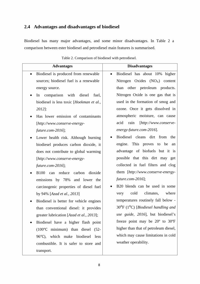
Biodiesel has many major advantages, and some minor disadvantages. In Table 2 a
comparison between ester biodiesel and petrodiesel main features is summarised.
Table 2. Comparison of biodiesel with petrodiesel. Advantages Disadvantages
• Biodiesel is produced from renewable
sources; biodiesel fuel is a renewable
energy source.
• In comparison with diesel fuel,
biodiesel is less toxic [Hoekman et al.,
2012]:
• Has lower emission of contaminants
[http://www.conserve-energy-
future.com-2016];
• Lower health risk. Although burning
biodiesel produces carbon dioxide, it
does not contribute to global warming
[http://www.conserve-energy-
future.com-2016];
• B100 can reduce carbon dioxide
emissions by 78% and lower the
carcinogenic properties of diesel fuel
by 94% [Azad et al., 2013]
• Biodiesel is better for vehicle engines
than conventional diesel: it provides
greater lubrication [Azad et al., 2013];
• Biodiesel have a higher flash point
(100℃ minimum) than diesel (52-
96℃), which make biodiesel less
combustible. It is safer to store and
transport.
• Biodiesel has about 10% higher
Nitrogen Oxides (NOX) content
than other petroleum products.
Nitrogen Oxide is one gas that is
used in the formation of smog and
ozone. Once it gets dissolved in
atmospheric moisture, can cause
acid rain [http://www.conserve-
energy-future.com-2016].
• Biodiesel cleans dirt from the
engine. This proves to be an
advantage of biofuels but it is
possible that this dirt may get
collected in fuel filters and clog
them [http://www.conserve-energy-
future.com-2016];
• B20 blends can be used in some
very cold climates, where
temperatures routinely fall below -
30⁰F (1⁰C) [Biodiesel handling and
use guide, 2016], but biodiesel’s
freeze point may be 20º to 30ºF
higher than that of petroleum diesel,
which may cause limitations in cold
weather operability.

9
2.5 Energy balance
According to biodiesel lifecycle studies, or energy balances, done by the United States
Department of Energy, it was concluded that the production and use of biodiesel reduces
78.5% of carbon dioxide emissions, unburned hydrocarbons and particulate matter. This can
be explained by biodiesel's partially closed carbon cycle [Biodiesel Instructor-2011] referred
above. Overall, from the biodiesel energy balance (see Table 3), it can be concluded that for
a unit of fossil energy needed to make biodiesel, 4.5 units of energy are gained. On the other
hand, regular fossil fuels take more energy to produce than they provide in return
[http://articles.extension.org-2016].
Table 3. Summary of Energy Balance/Energy Life Cycle [http://dartonrefuel.com/biodiesel.php/].
* Energy Yield - Life cycle yield in liquid fuel. BTU’s for each BTU of energy consumed
[http://dartonrefuel.com/biodiesel.php/].
2.6 The biodiesel production and consumption in the world
Due to its non-toxicity and biodegradability, biodiesel has become an alternative fuel in the
transportation sector, and a possible solution to environmental issues [Hassan et al., 2013].
The European Union is expanding its B5 (blend of 5% (v/v) biodiesel with 95% petrodiesel)
blend to a B7 (blend of 7% (v/v) biodiesel with 93% petrodiesel) specification as part of the
Fuel Quality Directive passed in December 2003. The renewable energy policy includes an
obligatory 10% goal for transportation fuels such as hydrogen, biofuels and electricity. This
new requirement updated the 5.75% renewable substitution aim of 2010, determined in
2003, to a more ambitious goal. However the 2003 aim of about 10% for biofuels in 2020
was kept as an obligatory aim. The greenhouse gas aim for biofuels to take effect in 2011
was set at a 35% decline when compared with fossil fuels. In 2017, the demand is raised to a
50% decrease, and for new producers after 2017, the aim will be 60%
Fuel Biodiesel Ethanol Diesel Gasoline
Energy Yield* 4.50 0.805 0.843 0.805
Net Energy (Loss) or Gain (%) 350 34 15.7 19.5

10
[www.biodieselmagazine.com-2016]. In Figure 1 the investment of different countries and
regions in biodiesel production is preesented [Johanson et al., 2012].
Figure 1. Biodiesel production in different countries, 2009-2010 [Johanson et al., 2012].
2.6.1 Biodiesel Consumption
Renewables sources have played an increasing role in the energy sector. In 2015 their
contribution was €16 billion and it is projected to be €58 billion in 2030, and thanks to fast
decreasing costs owing to technological advancement, especially in the power sector,
renewables can also be gradually further integrated in the market. Biodiesel is the main
biofuel used for transport in the EU, representing 79% of total use of biofuels in 2015. The
main consumers of biodiesel are France, Germany and Italy. Renewable energy in Transport
sector comes largely from biofuels (88%), with electricity playing a more limited role. In the
EU, biofuels production exceeded by three times the planned trajectory, with around 3
Million tons in 2015, mainly because of the utilization of used cooking oil. The share of
biofuels produced from wastes and residues, like waste cooking oils, in the EU has
increased from 1% in 2009 to 23% in 2015 [Renewable Energy Progress Report, 2017].

11
Figure 2. EU-28 renewable energy in transport, by source (source: EUROSTAT, Öko-Institut) [Renewable Energy Progress Report- 2017]
In EU, biodiesel consumption showed 0.5% marginal increase. In Figure 3, it is presented
the production of biodiesel in Portugal after 2006. The data of 2016 to 2018 is a forecast. In
Portugal the production of biodiesel from 2015 to 2016 increased 2.3% [Phillips et al.,
2016].
Figure 3. Production of biodiesel in Portugal 2006-2018 (Million litres) [Phillips et al., 2016].
2.6.2 Raw materials for Biodiesel production
Biodiesel is produced from vegetable oils all over the world. But, for biodiesel production, it
can also be used animal fats, like white grease or lard, fish fat and chicken fat [Ahmia et al.,
2014].

12
Figure 4 shows the relative importance of soybean oil as biodiesel feedstock in the EU and
Portugal. It can be seen that soybean oil is the major feedstock in Portugal and the second in
EU [Castanheira et al., 2015].
The most used oils for worldwide biodiesel production are rapeseed (EU), soybean
(Argentina and USA), and palm (Asian and Central America) and sunflower, although other
oils or fats are also used, including peanut, linseed, safflower, used vegetable oils, and
animal fats [Romano et al., 2011].
On the other hand non-edible oil feedstocks range from castor oil to jatropha, tung, cotton,
jojoba and microalgae oils, which proved to be highly promising and reliable sources,
having high oil content. Algae oil, due to its availability and low cost is considered as an
economical choice for biodiesel production [Gashaw et al., 2014].
Figure 4. Feedstock used for biodiesel production in the European Union and Portugal [Castanheira et al., 2015].
Microalgae, a large and diverse group of aquatic organisms that lack the complex cell
structures found in higher plants [Slade et al., 2013], appear to be a very important
alternative for future biodiesel production due to its potential oil yield; however, its
application for biofuel production is still commercially limited [Romano et al., 2011], due to
the highly energetic intensive technologies available for algae oil recovery.
2.7 Production of biodiesel
The recent interests in biodiesel reside in the regular rises in oil prices and the disappearing
resources of fossil fuels. These issues boosted the interest in biodiesel production from both
animal and vegetable fats. In fact, intensive usage of petroleum based materials and fuels are
13
an important factor in air pollution: an extremely important problem, as mankind may face a
global warming crisis [Earle et al. 2009].
Ester biodiesel, which is a mixture of Fatty Acid Methyl Esters (FAME), is made through
the transesterification of animal fat or vegetable oils. Fats are mainly constituted by
mixtures of triglycerides, which are triesters of glycerol, molecules with a glycerol core
connected to 3 fatty acid chains by ester groups. The most important fatty acid ester
derivative is oleic acid, but oils usually exhibit smaller contents of fatty acid saturated
chains (of varying lengths) and some double unsaturated chains (like linoleic acid ester
derivatives). For fatty esters, both acid- and base-catalysed transesterifications reactions are
possible. However, base catalysed transesterification to methyl or ethyl esters usually
require slightly higher reaction temperatures [Earle et al., 2009].
Biodiesel can also be produced by esterification of free fatty acids (FFAs) derived from
vegetable oils, with separation of the water by-product from the FAME product. For fatty
acids, the acid-catalysed esterification reaction is preferred. The base-catalysed esterification
to methyl and ethyl esters is not used because the catalyst is deactivated by reaction with the
carboxylic acid group to form a carboxylic acid salt, which is often called soap [Earle et al.,
2009].
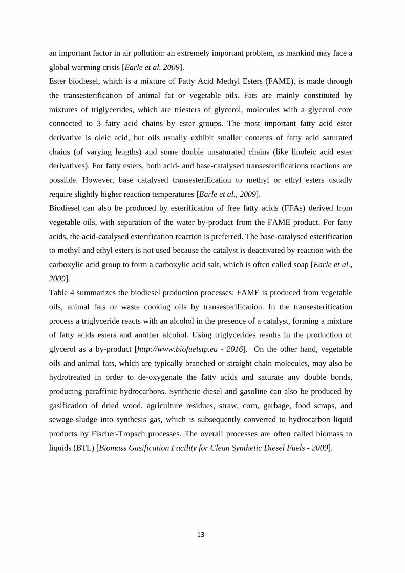
Table 4 summarizes the biodiesel production processes: FAME is produced from vegetable
oils, animal fats or waste cooking oils by transesterification. In the transesterification
process a triglyceride reacts with an alcohol in the presence of a catalyst, forming a mixture
of fatty acids esters and another alcohol. Using triglycerides results in the production of
glycerol as a by-product [http://www.biofuelstp.eu - 2016]. On the other hand, vegetable
oils and animal fats, which are typically branched or straight chain molecules, may also be
hydrotreated in order to de-oxygenate the fatty acids and saturate any double bonds,
producing paraffinic hydrocarbons. Synthetic diesel and gasoline can also be produced by
gasification of dried wood, agriculture residues, straw, corn, garbage, food scraps, and
sewage-sludge into synthesis gas, which is subsequently converted to hydrocarbon liquid
products by Fischer-Tropsch processes. The overall processes are often called biomass to
liquids (BTL) [Biomass Gasification Facility for Clean Synthetic Diesel Fuels - 2009].
14
Table 4. Methods for biodiesel production [Pacini et al., 2014].
Process Feedstock Product
Transesterification Vegetable oils and animal fat Fatty acidy methyl ester
(FAME)+Glycerol
Hydrotreating Vegetable oils and animal fat Hydrotreated vegetable oil (HVO)+
Paraffin
Gasification
+Fischer Tropsch
Wood, energy crops, agriculture
residues, waste etc. Biomass to liquid fuel(BTL)
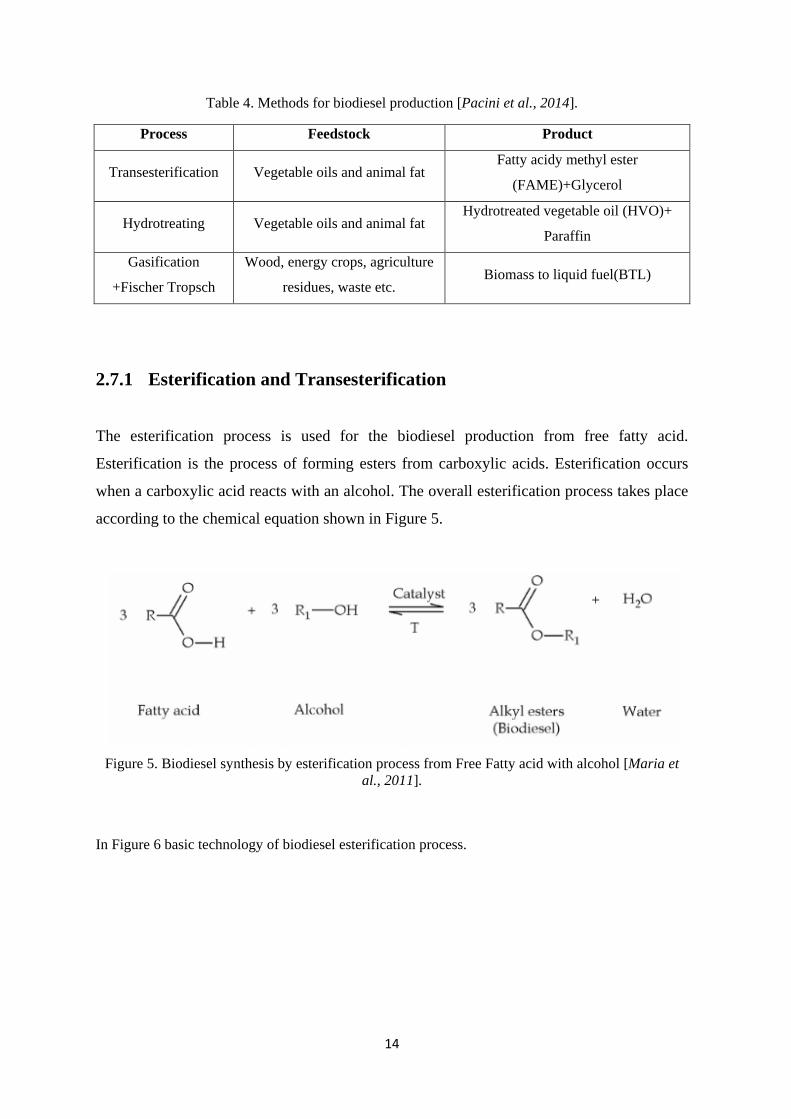
2.7.1 Esterification and Transesterification
The esterification process is used for the biodiesel production from free fatty acid.
Esterification is the process of forming esters from carboxylic acids. Esterification occurs
when a carboxylic acid reacts with an alcohol. The overall esterification process takes place
according to the chemical equation shown in Figure 5.
Figure 5. Biodiesel synthesis by esterification process from Free Fatty acid with alcohol [Maria et
al., 2011].
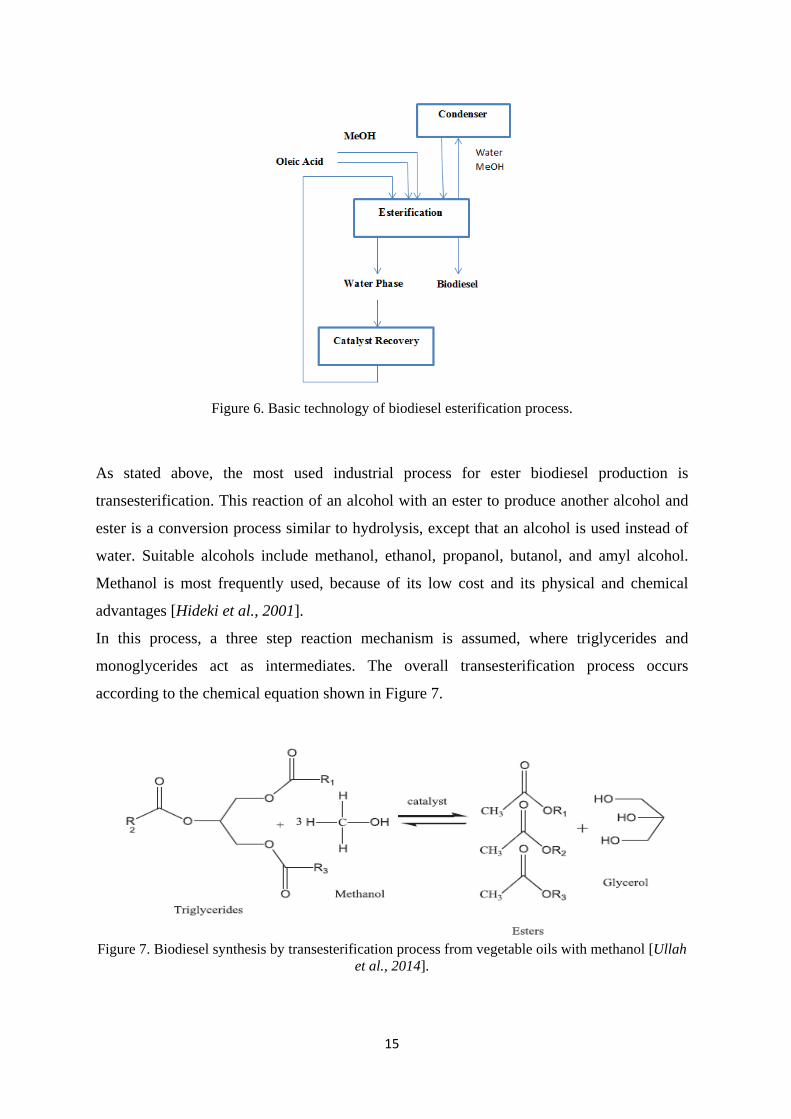
In Figure 6 basic technology of biodiesel esterification process.
15
Figure 6. Basic technology of biodiesel esterification process.
As stated above, the most used industrial process for ester biodiesel production is
transesterification. This reaction of an alcohol with an ester to produce another alcohol and
ester is a conversion process similar to hydrolysis, except that an alcohol is used instead of
water. Suitable alcohols include methanol, ethanol, propanol, butanol, and amyl alcohol.
Methanol is most frequently used, because of its low cost and its physical and chemical
advantages [Hideki et al., 2001].
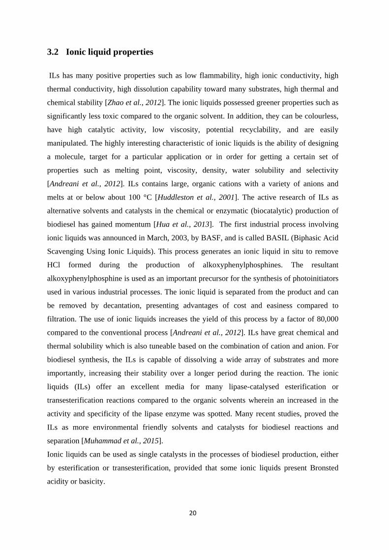
In this process, a three step reaction mechanism is assumed, where triglycerides and
monoglycerides act as intermediates. The overall transesterification process occurs
according to the chemical equation shown in Figure 7.
Figure 7. Biodiesel synthesis by transesterification process from vegetable oils with methanol [Ullah
et al., 2014].

16
Considering a base catalysed process, an amount of alkali (for example NaOH) slowly
dissolves in alcohol excess (usually methanol). This methoxide mixture is mixed with warm
preheated oil at about 50℃, and allowed to react for 1 to 8 hours to ensure a complete
transesterification reaction. In pressurised conditions, the reaction mixture may be
maintained above the alcohol boiling point (70℃), but for normal pressure systems, it is
recommended to maintain the temperature range from room temperature to 55 ℃, for safety
reasons. Under normal pressure conditions, the reaction time is usually from 1 to 10 hours,
and it is important to avoid a sealed system in order to prevent the risk of explosion, because
the reaction rate is doubled by raising the reaction temperature by 10 ℃. In pressurised
conditions and to prevent evaporation of the alcohol, the reaction should be carried out in a
closed container [www.bioethanol.ru-2016] or using a reflux process. In Figure 8 it is shown
the basic technology for ester biodiesel production.
The use of mineral acids in acid catalysed processes has some disadvantages such as
equipment corrosion, long workup procedure and environmental problems. Recently,
replacement of these hazardous liquid acids by solid acid catalysts has been essential, but
these catalysts show also some disadvantages such as low activity, easy deactivation and
adsorption/desorption of products [Aghabarari et al., 2013].
Figure 8. Basic technology of biodiesel transesterification process [www.bioethanol.ru-2016].

17
3 Ionic liquids
An ionic liquid is a molten salt consisting of a cation and an anion, with low melting
temperature. The earliest discovery of ionic liquids (ILs) was in the mid nineteenth-century
when “red oil”, generated by Friedel-Crafts reaction, was used as a solvent for separation
analysis. In 1914 Paul Walden reported the first widely-known ionic liquid, ethyl
ammonium nitrate. Interest in the study of ionic liquids became more intense in 1963, after
the research project of Major (Dr.) Lowell A. King of the US Air Force Academy. Later, in
1990, the professor from US Air Force Academy, Dr. Mike Zaworodko discovered the
solution for the problems faced by Dr. King which gave a new dimension for using of ionic
liquids in electrochemistry. Since then, due to its unique properties and possible uses, ILs
drew the interest of scientific researches and even several industries [Terencia et al., 2010].
ILs consist of ions and remain liquid at temperatures lower than 100 ◦C. Typical IL cations
are nitrogen-containing (such as alkylammonium, N-dialkylimidazolium, N-alkylpyridinium
and pyrrolidinium), or phosphorous containing (such as alkylphosphonium). The common
choices of anions include halides, BF4– , PF6
– , CH3CO2– , CF3CO2
– , NO3– , Tf2N–
[i.e.,(CF3SO2)2N]– , [RSO4] and [R2PO4] [Zhao et al., 2012]. The overall properties of ILs
derived from the composite properties of the cations and anions and include those that are
superacidic, basic, hydrophilic, water miscible, and water immiscible and hydrophobic. The
anion is currently used to control the water solubility, but the cation can also influence the
hydrophobicity or hydrogen bonding ability [Huddleston et al., 2001]. Some cations and
anions are shown in Figure 9.
Imidazolium-based ionic liquids have been used as green solvents to replace the volatile and
relatively toxic organic solvents, in homogeneous and heterogeneous catalysis, materials
science, nano materials, lithium ion batteries, and separation technology. Imidazolium based
ionic liquids, because of its inherent ionic patterns, low pressure and ability of self-
organization in different states, are considered as the most studied species [Woon et. al.,
2012].

18
Anions:
Cations:
Figure 9. Chemical structure of ionic liquids [http://www.sigmaaldrich.com-2016].
3.1 Classification of ionic liquids
Ionic liquids are good solvents, environmentally benign, nonvolatile, nonflammable, and
stable in air or water. Because of these special properties, ionic liquids have been widely
investigated as solvents for synthetic chemistry and catalysis [Zhang et al., 2007]. Ionic
liquids are generally divided into two broad classes, one based on chlorometallate anions
such as heptachlorodialuminate ([Al2Cl7]-) and the other based on anions not containing
metals, such as hexafluorophosphate ([PF6]-) [Andreani et al., 2012]. There are a large
number of imidazolium-based ILs, few ILs based on quaternary ammonium have been
reported. Quaternary ammonium salts (“quats”) because of its surface-active properties,
possess anti-microbial activity are an economically advantageous class of industrial
compounds. Most of these solvents remove lignin and alter cellulose structure, which
increases the accessibility of cellulolytic enzymes [Visser et al., 2007].

19
Tetrofluoroborate Thyocyanate
Dicyaneamide Hexafluorophosphate
Figure 10. Selected anions of phosphonium- and ammonium-based ILs [Stojanovic et al., 2011].
ILs plays a crucial role when applied as solvents or catalysts for different reactions at high
temperatures, or if the reaction products should be distilled from the ionic liquid at high
temperatures Ammonium and phosphonium ILs both can decompose at elevated
temperatures, but phosphonium salts are generally more stable as their ammonium analogs
[Stojanovic et al., 2011].
In this work different Ionic Liquids, were studied, with structures presented in Figure 11.
1-Butyl-3-methylimidazolium chloride 1-Butyl-3-methylimidazolium hydrogen sulfate
1-Butyl-3-methylimidazolium methyl sulfate Tributylmethylammonium methyl sulfate
1-Methylimidazolium hydrogen sulfate 1-Butyl-3-methylimidazolium methanesulfonate
Figure 11. Structure of different ILs
20
3.2 Ionic liquid properties
ILs has many positive properties such as low flammability, high ionic conductivity, high
thermal conductivity, high dissolution capability toward many substrates, high thermal and
chemical stability [Zhao et al., 2012]. The ionic liquids possessed greener properties such as
significantly less toxic compared to the organic solvent. In addition, they can be colourless,
have high catalytic activity, low viscosity, potential recyclability, and are easily
manipulated. The highly interesting characteristic of ionic liquids is the ability of designing
a molecule, target for a particular application or in order for getting a certain set of
properties such as melting point, viscosity, density, water solubility and selectivity
[Andreani et al., 2012]. ILs contains large, organic cations with a variety of anions and
melts at or below about 100 °C [Huddleston et al., 2001]. The active research of ILs as
alternative solvents and catalysts in the chemical or enzymatic (biocatalytic) production of
biodiesel has gained momentum [Hua et al., 2013]. The first industrial process involving
ionic liquids was announced in March, 2003, by BASF, and is called BASIL (Biphasic Acid
Scavenging Using Ionic Liquids). This process generates an ionic liquid in situ to remove
HCl formed during the production of alkoxyphenylphosphines. The resultant
alkoxyphenylphosphine is used as an important precursor for the synthesis of photoinitiators
used in various industrial processes. The ionic liquid is separated from the product and can
be removed by decantation, presenting advantages of cost and easiness compared to
filtration. The use of ionic liquids increases the yield of this process by a factor of 80,000
compared to the conventional process [Andreani et al., 2012]. ILs have great chemical and
thermal solubility which is also tuneable based on the combination of cation and anion. For
biodiesel synthesis, the ILs is capable of dissolving a wide array of substrates and more
importantly, increasing their stability over a longer period during the reaction. The ionic
liquids (ILs) offer an excellent media for many lipase-catalysed esterification or
transesterification reactions compared to the organic solvents wherein an increased in the
activity and specificity of the lipase enzyme was spotted. Many recent studies, proved the
ILs as more environmental friendly solvents and catalysts for biodiesel reactions and
separation [Muhammad et al., 2015].
Ionic liquids can be used as single catalysts in the processes of biodiesel production, either
by esterification or transesterification, provided that some ionic liquids present Bronsted
acidity or basicity.

21
Bronsted acidic ILs, were highly efficient catalyst for biodiesel synthesis from vegetable
oils. Sulfuric acid groups in these ILs are the active sites for transesterification [Guo et al.,
2011].
Currently, there are several scientific works published about the production of biodiesel
using ionic liquids. Some of these works are referred in Table 5.
• Ren and co-workers studied the production of biodiesel using as catalyst [Hnmm]
OH, a basic ionic IL. The raw material used was soybean oil. They analysed several
reaction parameters such as the influence of catalyst concentration on the biodiesel
yield, the effect of methanol / soybean oil molar ratio and the effect of reaction time.
The authors found out that the catalyst had an excellent catalytic performance at 70
°C reaction temperature, 1.5 h of reaction time, 3% wt catalyst dosage and a molar
ratio of MeOH/oil = 8/1. The obtained reaction yield was about 90% [Ren et. al.,
2014].
• In 2011, the production of biodiesel was studied by Guo et al., using as catalyst
[BMIM][CH3SO3] –FeCl3 and [BMIM][CH3SO3] –AlCl3, a basic ionic IL. The raw
material used was Jatropha oil. At high temperature of 120 °C, the reaction time 5 h.
𝐹𝑒3+ had a relatively higher activity than that of Al3+ (99.7% vs. 94%).
• Using palm oil and BMIMHSO4 as catalyst, a reaction temperature of 160 ºC, 1 h for
the reaction time and 1% wt of catalyst, [ Elsheikh et al., 2011], obtained a reaction
yield of 98.4%.
• In another experiments from Fang and his colleagues different catalysts [C4MIM]
[NTf2] and [C2MIM][TfO] were used for production of biodiesel. During all
experiments raw material used Soybean oil. The first experiment was at room
temperature, second experiment was at 50 °C and reaction time is 12 h. The reaction
yield was 96 % and 80 % [Fang et al., 2014].
• For production biodiesel is used triolein oils with different catalysts
([C18MIM][NTf2] and [C16MIM][NTf2]), a basic ionic IL. The process was doing in
the same temperature (60°C). The one experiment was a 6 h; another experiment was
a 24 h. The reaction yield was 96 %, 99% [Fang et al., 2014].
• The production of biodiesel from waste cooking oil was studied by Ullah and co-
workers. They used as catalyst BMIMHSO4, a basic ionic IL. The catalyst was
efficient in the first hour of reaction with the yield reaching up to 95.65%. After that
there was no considerable change in the yield, therefore the reaction time of 1 h was

22
identified as the optimum reaction time, at high temperature of 160 °C [Ullah et
al.,2015].
Table 5. Recent published studies using different oils and ionic liquids for biodiesel production. Effect of reaction and time reaction on production yield
Oils Ionic Liquids T(℃) Time(h) Yield(%)
Soybean oil
[Ren et al., 2014]
[Hnmm]OH
70 1.5 97
Jatropha oil
[Guo et al.,2011]
[BMIM][CH3SO3] –AlCl3
120 5 94
Jatropha oil
[Guo et al.,2011] [BMIM][CH3SO3] –FeCl3 120 5 99.7
Crude palm oil
[Elsheikh et al.,2011] BMIMHSO4 160 1 98.4
Triolein
[Fang et al.,2014] [C18MIM][NTf2] 60 6 96
Myglyol oil
[Fang et al.,2014] Cholrine acetate 40 3 97
Cooking oil
[Fang et al.,2014]
1ethyl,3methyl
Imidazolium
trifluromethane sulfonate
40 24 99
Soybean oil
[Fang-2014] [C4MIM][NTf2 ]
Room
Temperature 12 96
Triolein
[Fang et al.,2014] [C16MIM][NTf2] 60 24 99
Soybean oil
[Fang et al.,2014] [C2MIM][TfO] 50 12 80
Waste Cooking Oil
[Ullah et al.,2015] [BMIM][HSO4] 160 1 95.65
3.3 The role of ionic liquids in transesterification reactions
In biodiesel production from vegetable oils and animal fats, depending on the catalyst used,
there are specific characteristics related with these reactions. For example, acid catalysts are
mainly used when the oil has a high concentration of free fatty acids, with sulphuric and
23
sulfonic acids as the most common catalysts of this class. As disadvantages, the acid
catalysis requires the use of large amounts of alcohol additionally; acid catalysts such as
sulphuric acid catalyse the transesterification of triglycerides slowly even when refluxing
with methanol, leading to long reaction times such as 48-96 hours. And there is the risk of
corrosion of the equipment used due to the high acidity of those catalysts [Adreani et al.,
2012].
Ionic liquids are more expensive than conventional solvents and catalysts used in chemical
reactions. Two of the most commonly used ionic liquids are 1-n-butyl-3-methylimidazolium
tetrafluoroborate ([BMI][BF4]) and 1-n-butyl-3-methylimidazolium hexafluorophosphate
([BMI][PF6]) [Andreani et al, 2012]. But the use of ionic liquids in catalytic systems seems
to be environmentally secure. The possibility of recovery and reuse of ionic liquids
minimizes the waste in catalytic reactions. Ionic liquids have been using in most number of
chemical reaction types. The important advantage of using ionic liquids in reactions is their
non-volatility except at high pressures and low temperatures. ILs possesse numerous
advantages over the conventional organic solvents (they possessed greener properties such
as very low relative volatility i.e., wide liquid temperature and significantly less toxic
compared to the organic solvent). More important is their ability to selectively dissolve
various organic, inorganic, and organometallic materials due to their tuneable polarity which
can be designed for specific purposes. In view of the environmental friendly nature of ILs,
the catalyst also referred to as green catalyst. ILs is considered prospective catalysts for
biodiesel production. Using ILs based catalyst could reduce the number of reactions and
purification steps required in the biodiesel preparation and separation hence rendering the
process to be more economically competitive [Muhammad et al., 2015].
3.4 Ionic Liquids recovery
In nowadays ILs can be used for developing new processes that are technologically,
environmentally and economically advantageous. However ILs has typically high costs. So,
for an improvement in the economic, efficiency the recycling and reuse of ILs are critical.
Also, recovery of ILs is important to minimise the environmental concerns of the disposal,
like biodegradation and toxicity (they can be mixed with other products). Even though ILs is
considered as homogeneous catalysts because they are in the same phase as the reactants, its
capability to be recovered and recycled is an advantage over conventional homogeneous

24
solvents. For the recovery and recycle of ILs the most used method is distillation, because
ILs show low vapour pressures. It is important to note that the interaction of ILs with water,
which is mainly affected by the size of ILs, hydrophobicity and hydrogen bonding ability of
both cations and anions, will determine the techniques used for its recovery. Among these
effects, the nature of anions largely determines the behaviour of the IL-water mixture.
Hydrophobic ILs which is immiscible with water can be easily separated from water by
decantation. Additionally, many molecular solvents including water are immiscible with ILs
and can be used to extract or separate materials from the IL solutions [Freire et al., 2007].
For the recovery of ILs there are used different methods
• Distillation is the simplest method for the recovery of ILs. First ILs is removed by
decantation, filtration and/or extraction, and also by washing with water/organic
solvents. After that, distillation can be used for recycling and reuse of ILs [Mai et
al., 2014]. For example [BMIM][FeCl4] IL is heated in the oven at 105 ºC for 24 h to
evaporate water [Fauzi et al., 2014]. For recovery of [BMIM][HSO4], it is washed
with distilled water to remove any impurities, and afterwards heated in the oven at
105 ºC for 24 h to remove traces of water and unreacted methanol [Fauzi, 2014].
[HMIM][HSO4] can be used in the ester exchange reaction after washing with ethyl
acetate; excess ethyl acetate was removed by reduced-pressure distillation. It was
found that [HMIM][HSO4] recycled 4 times can still retain stable catalytic
performance [Xu Wei et al., 2015]. Adsorption can be used for retaining ILs onto
solid supports such as activated carbon (AC), silica (SiO2), alumina (Al2O3),
titanium dioxide (TiO2), and clays [Mai et al., 2014].
• After reaction the water was added to the reaction mixture and then the solid was
isolated by filtration. The IL in water could be recovered easily by evaporation at 80
ºC in a vacuum. The recovered IL was washed with diethyl ether and dried at 80ºC
in a vacuum for 1h [Abbaspour-Gilandeha, 2014].
• An alternative method for recovery ILs which does not use high thermal application
is extraction of IL using carbon dioxide. Blanchard and Brennecke demonstrated the
separation of an ionic liquid ([BMIM] [PF6]) from a number of organic compounds
using supercritical carbon dioxide (SCCO2) extraction method. The method is
effective because organic compounds are soluble in CO2, while ILs is insoluble. This
25
enabled the separation of organic compounds from IL, and depressurization is then
applied to remove solutes from CO2 [Fauzi et al., 2012].
• Recovery of ILs can also be performed by crystallization processes. Using this
method, crystals of ILs are easily separated from the reaction mixture as they are in
different phases. The temperature at which the IL solidifies are important in this
method. Hayyan studied the use of 1-butanol as an anti-solvent for the separation of
choline chloride from glycerin after the transesterification process. After the
introduction of the anti-solvent into the glycerin phase, the temperature was reduced
to -20 °C, and the crystals of choline chloride were separated. Further filtration under
vacuum was required to recover the IL [Fauzi et al., 2012].
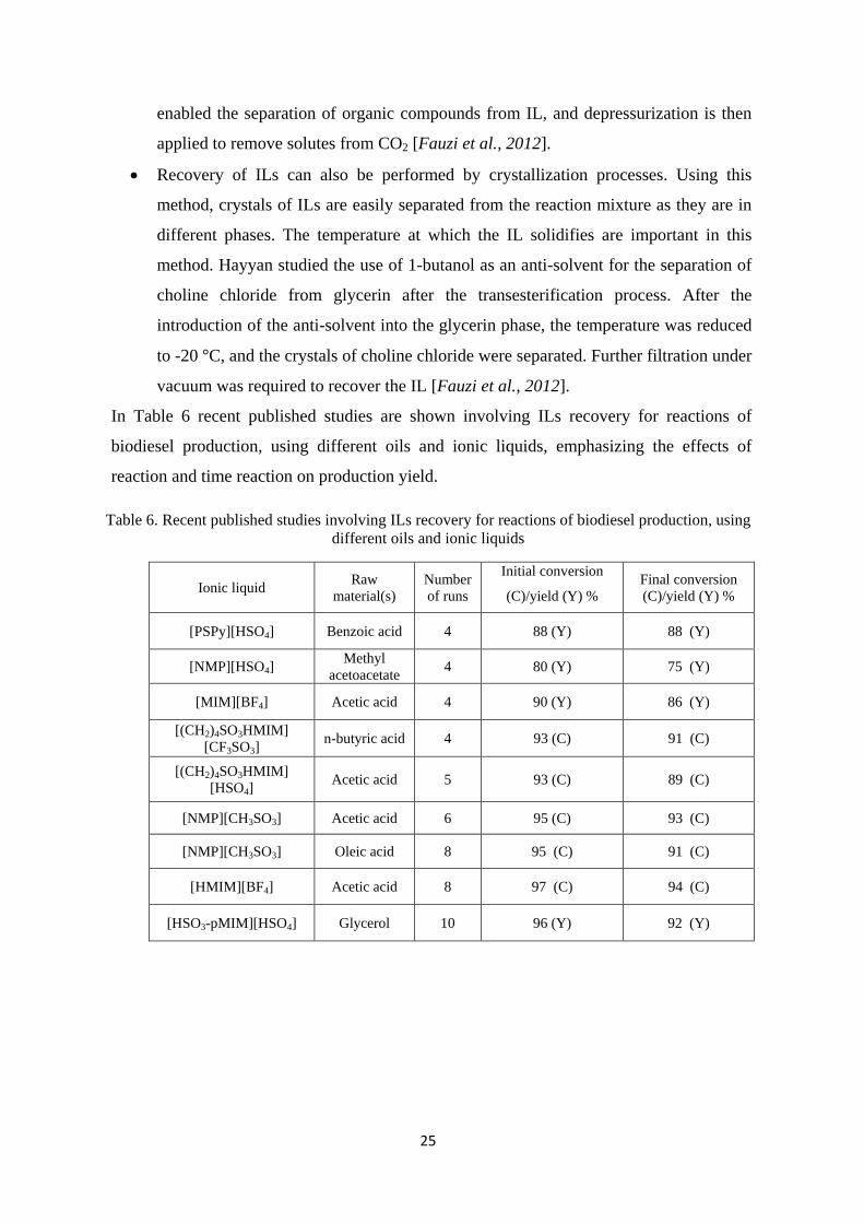
In Table 6 recent published studies are shown involving ILs recovery for reactions of
biodiesel production, using different oils and ionic liquids, emphasizing the effects of
reaction and time reaction on production yield.
Table 6. Recent published studies involving ILs recovery for reactions of biodiesel production, using different oils and ionic liquids
Ionic liquid Raw material(s)
Number of runs
Initial conversion
(C)/yield (Y) % Final conversion (C)/yield (Y) %
[PSPy][HSO4] Benzoic acid 4 88 (Y) 88 (Y)
[NMP][HSO4] Methyl
acetoacetate 4 80 (Y) 75 (Y)
[MIM][BF4] Acetic acid 4 90 (Y) 86 (Y)
[(CH2)4SO3HMIM] [CF3SO3]
n-butyric acid 4 93 (C) 91 (C)
[(CH2)4SO3HMIM] [HSO4]
Acetic acid 5 93 (C) 89 (C)
[NMP][CH3SO3] Acetic acid 6 95 (C) 93 (C)
[NMP][CH3SO3] Oleic acid 8 95 (C) 91 (C)
[HMIM][BF4] Acetic acid 8 97 (C) 94 (C)
[HSO3-pMIM][HSO4] Glycerol 10 96 (Y) 92 (Y)

26
4 Experimental
4.1 Introduction
The first experimental task of this work was the selection of a suitable ionic liquid in order
to study the effect its recovery and use in a set of 4 or 5 consecutive esterification reactions.
All the 5 ILs available in the LQA laboratory were tested and only one IL was chosen.
Then, several esterification reactions were performed using three different amounts (%) of
ionic liquid. After each reaction, the obtained samples were separated in aqueous and
organic phases by decantation and centrifugation. Both organic (biodiesel) and aqueous
(with ionic liquid) samples were dried and stored in the refrigerator (4 ºC) for further
analysis. After each reaction test, the reaction yield was determined using the acidity of the
organic phase measured by volumetric titration. The characterization of the produced
biodiesel samples was measured qualitatively and quantitatively by determination of Fatty
Acid Methyl Esters content by the Gas Chromatography (GC). Additionally, initial and final
samples of the selected ionic liquid were characterized by UV-Vis and FT-IR spectroscopy.
4.2 Chemicals and Equipment
Oleic acid (cis-9-octadecenoic acid) (≥90%) was purchased from Fluka and heptadecanoate
methyl ester (≥97%), used as internal standard in the GC analysis was obtained from TCI
Company, Japan. Five different ionic liquids: 1-butyl-3-methylimidazolium hydrogen
sulfate (≥94.5%), 1-butyl-3-methylimidazolium methyl sulfate (≥95%), 1-
methylimidazolium hydrogen sulfate (≥95%), 1-butyl-3-methylimidazolium
methansulfanate (≥95%) were purchased from Sigma-Aldrich, Switzerland and the
tributylmethylammonium methyl sulfate from Chem Cruz Company, United States. It was
also used: Methanol (≥99.9%) from Carlo Erba; heptane (≥90%) from Fluka; potassium
hydroxide from Riedel-deHaen; hydrochloric acid (≥37%) from Fisher; Ethanol (absolute)
and diethyl ether (≥99.8%) from Carlo Erba; and sodium tetraborate and anhydrous sodium
sulfate were obtained from Carlo Erba. 37 FAME mix standard solution from Supelco, and
sulfuric acid (≥95.0-97.0%) from Sigma-Aldrich, Switzerland, were also used.

27
The chemical formula and molecular weight of oleic acid and the 5 ionic liquids studied in
this work are presented in Table 7.
Table 7. Chemical formula, density and molecular weight of oleic acid and the 5 ionic liquids.
Name Chemical formula MW (g/mol)
Oleic acid C18H34O2 282.46
1-Butyl-3-methylimidazolium
hydrogen sulfate [BMIM][HSO4] 236.29
1-Butyl-3-methylimidazolium
methyl sulfate [BMIM][MeSO4] 250.32
1-Methylimidazolium Hydrogen sulfate [MIM][HSO4] 180.18
1-Butyl-3-methylimidazolium methanesulfonate
[BMIM][CH3SO4] 234.32
Tributylmethylammonium methyl sulfate C14H33NO4S 311.48
The characterization of biodiesel samples was performed using a VARIAN CP-3800 Gas
Chromatography system equipped with a FID detector. For ILs characterization (before and
after recovery) a Barnstead Lab Line 3618-5 Vacuum Oven from Thermo Scientific, a
VARIAN Cary 50 UV-Vis and a FT-IR ABB model MB3000 spectrophotometers were
used.
4.3 Biodiesel Production by Esterification Reaction
The esterification reaction was carried out in a 100 mL glass reactor with continuous
stirring, connected to a reflux condenser and a thermometer (Figure 12). The methanol and
oleic acid (1:10 molar ratio), in this order, were added into the glass reactor. The reactor
containing the mixture was then immersed into a paraffin bath. The reactor was then heated
until a temperature of 90oC and methanol was added to the reactor.

28
Figure 12. Experimental setup for the esterification: 1) Heater 2) Reactor 3) Condenser.
The reaction was stopped after 6 hours and then the reactor was cooled to room temperature.
It was verified the formation of a single phase inside the reactor. After cooling, the mixture
was removed from the reactor and transferred into centrifugal tubes (Figure 13). Then the
mixture was centrifuged during 20 minutes at 3000 rpm and the samples inside the tubes
were stored in the fridge (4 ºC).
Figure 13. Tubes with the mixture after reaction: 1) Organic phase 2) Water phase.

29
After 24 h into the fridge, the mixture was able to separate into two phases. The phases were
separated using a pipette and the mass of each phase was measured using an analytical
balance Adam Equipment ADA-210/I Balance.
Both phases were then stored in 10 mL brown flasks inside the fridge for further analysis:
acidity determination, and characterization by GC, UV-Vis and FT-IR.
4.4 Recovery of ILs
In this work the esterification reaction was studied for biodiesel production using ILs as
catalysts. The reactions were carried out with three different [BMIM][H2SO4] amounts
(10%, 15% and 20% wt). In each reaction the IL samples were recovered and reused in a
following reaction test maintaining the same IL amount relating to the initial oleic acid
weight. 4 runs were done in 10% reaction sequence, and for 15% and 20% reactions
sequences, 5 runs were done. The recovery procedure is described below:
a. After 2 days from the reaction test, the separation of phases were concluded (see
Figure 14);
b. The organic phase (biodiesel) was analysed by calculating its acidity;
Figure 14. Separation Phases.

30
c. The water phase was treated by evaporation for IL recovery: first it is heated for 1
hour at 110 ℃ afterwards the sample is introduced in a vacuum oven at 60℃ for 12-
15 h (see Figure 15).
Figure 15. Vacuum oven.
After evaporation, the ILs were recovered and used for the next reaction. In Figure 16 there
are presented examples of phases before and after IL recovery for the 15% and 20% runs.
a) Before Recovery b) After Recovery
Figure 16. ILs samples before and after recovery.

31
4.4.1 Biodiesel Acidity Measurements
For biodiesel analysis a titration method was used (Method EN 14104:2003). First, an HCl
0.1M solution was prepared and standardized with borax. Then, a KOH alcoholic 0.1 mol/L
solution was prepared and its concentration was checked with the standardized HCl
solution. After that 1L of solvent (Ethanol/Diethyl ether 1/1) was also prepared and the
standardized solution of KOH was diluted to a 0.01M concentration. These solutions were
used for the determination of the acidity of oleic acid and biodiesel samples.
a) Determination of acidity of oleic acid/biodiesel (with alcoholic solution of KOH)
For volumetric titration diethyl ester/ethanol 1:1 (v/v) solution was used as the solvent and
phenolphthalein was used as the indicator. First 40 mL of solvent were titrated adding 5
drops of phenolphthalein and stirring the mixture while the KOH standard solution was
added from the burette in order to neutralize the solution until the color changes to light
pink. After that 1 mL of biodiesel sample was weighed using a precision balance, and
titrated with the same solvent, until achieving pink color.
The acidity of the samples is determined by equation 1.
𝐴𝑐𝑖𝑑 𝑣𝑎𝑙𝑢𝑒,𝐴𝑉 � 𝑚𝑔 𝐾𝑂𝐻𝑔 𝑏𝑖𝑜𝑑𝑖𝑒𝑠𝑒𝑙
� = 𝑉∗𝐶𝐾𝑂𝐻∗𝑀𝑊(𝐾𝑂𝐻)
𝑚𝑏𝑖𝑜𝑑𝑖𝑒𝑠𝑒𝑙 (1)
where:
V - Volume of KOH standard solution needed to titrate the sample (mL)
𝐂𝐊𝐎𝐇 - Concentration of potassium hydroxide standard solution (KOH) (mol/L)
𝐌𝐖(𝐊𝐎𝐇) - Molecular weight of KOH = 56.1 (g/mol)
𝐦𝐛𝐢𝐨𝐝𝐢𝐞𝐬𝐞𝐥 - Weight of sample (g).
b) Determination of the biodiesel yield
The produced biodiesel is a result from the reaction between oleic acid and methanol, in the
presence of a catalyst (IL). Biodiesel is constituted by methyl esters. The yield of the
esterification reaction can be quantified by determining the acidity level according to
equation (2):
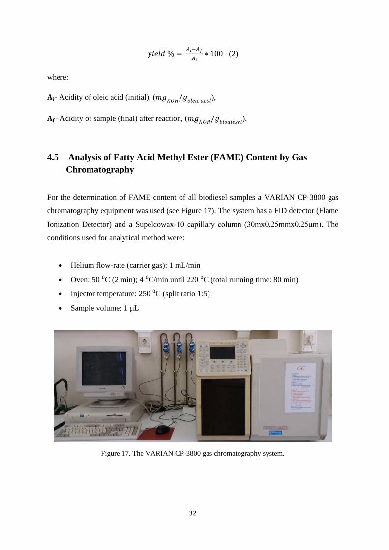
32
𝑦𝑖𝑒𝑙𝑑 % = 𝐴𝑖−𝐴𝑓𝐴𝑖
∗ 100 (2)
where:
𝐀𝐢- Acidity of oleic acid (initial), (𝑚𝑔𝐾𝑂𝐻/𝑔𝑜𝑙𝑒𝑖𝑐 𝑎𝑐𝑖𝑑),
𝐀𝐟- Acidity of sample (final) after reaction, (𝑚𝑔𝐾𝑂𝐻/𝑔𝑏𝑖𝑜𝑑𝑖𝑒𝑠𝑒𝑙).
4.5 Analysis of Fatty Acid Methyl Ester (FAME) Content by Gas Chromatography
For the determination of FAME content of all biodiesel samples a VARIAN CP-3800 gas
chromatography equipment was used (see Figure 17). The system has a FID detector (Flame
Ionization Detector) and a Supelcowax-10 capillary column (30mx0.25mmx0.25μm). The
conditions used for analytical method were:
• Helium flow-rate (carrier gas): 1 mL/min
• Oven: 50 ⁰C (2 min); 4 ⁰C/min until 220 ⁰C (total running time: 80 min)
• Injector temperature: 250 ⁰C (split ratio 1:5)
• Sample volume: 1 µL
Figure 17. The VARIAN CP-3800 gas chromatography system.
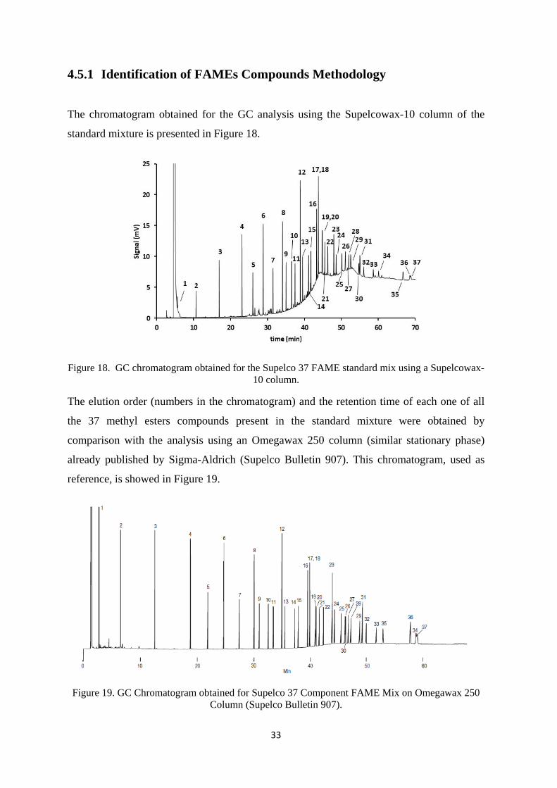
33
4.5.1 Identification of FAMEs Compounds Methodology
The chromatogram obtained for the GC analysis using the Supelcowax-10 column of the
standard mixture is presented in Figure 18.
Figure 18. GC chromatogram obtained for the Supelco 37 FAME standard mix using a Supelcowax-10 column.
The elution order (numbers in the chromatogram) and the retention time of each one of all
the 37 methyl esters compounds present in the standard mixture were obtained by
comparison with the analysis using an Omegawax 250 column (similar stationary phase)
already published by Sigma-Aldrich (Supelco Bulletin 907). This chromatogram, used as
reference, is showed in Figure 19.
Figure 19. GC Chromatogram obtained for Supelco 37 Component FAME Mix on Omegawax 250 Column (Supelco Bulletin 907).
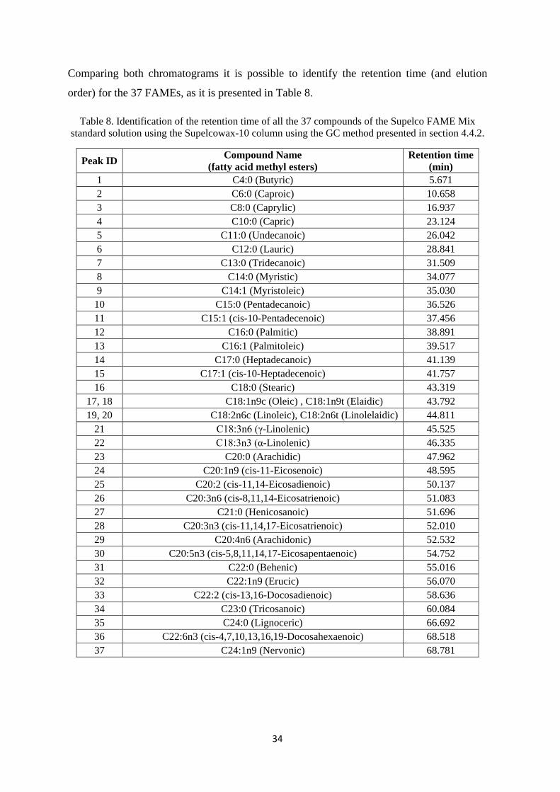
34
Comparing both chromatograms it is possible to identify the retention time (and elution
order) for the 37 FAMEs, as it is presented in Table 8.
Table 8. Identification of the retention time of all the 37 compounds of the Supelco FAME Mix standard solution using the Supelcowax-10 column using the GC method presented in section 4.4.2.
Peak ID Compound Name (fatty acid methyl esters)
Retention time (min)
1 C4:0 (Butyric) 5.671 2 C6:0 (Caproic) 10.658 3 C8:0 (Caprylic) 16.937 4 C10:0 (Capric) 23.124 5 C11:0 (Undecanoic) 26.042 6 C12:0 (Lauric) 28.841 7 C13:0 (Tridecanoic) 31.509 8 C14:0 (Myristic) 34.077 9 C14:1 (Myristoleic) 35.030 10 C15:0 (Pentadecanoic) 36.526 11 C15:1 (cis-10-Pentadecenoic) 37.456 12 C16:0 (Palmitic) 38.891 13 C16:1 (Palmitoleic) 39.517 14 C17:0 (Heptadecanoic) 41.139 15 C17:1 (cis-10-Heptadecenoic) 41.757 16 C18:0 (Stearic) 43.319
17, 18 C18:1n9c (Oleic) , C18:1n9t (Elaidic) 43.792 19, 20 C18:2n6c (Linoleic), C18:2n6t (Linolelaidic) 44.811
21 C18:3n6 (γ-Linolenic) 45.525 22 C18:3n3 (α-Linolenic) 46.335 23 C20:0 (Arachidic) 47.962 24 C20:1n9 (cis-11-Eicosenoic) 48.595 25 C20:2 (cis-11,14-Eicosadienoic) 50.137 26 C20:3n6 (cis-8,11,14-Eicosatrienoic) 51.083 27 C21:0 (Henicosanoic) 51.696 28 C20:3n3 (cis-11,14,17-Eicosatrienoic) 52.010 29 C20:4n6 (Arachidonic) 52.532 30 C20:5n3 (cis-5,8,11,14,17-Eicosapentaenoic) 54.752 31 C22:0 (Behenic) 55.016 32 C22:1n9 (Erucic) 56.070 33 C22:2 (cis-13,16-Docosadienoic) 58.636 34 C23:0 (Tricosanoic) 60.084 35 C24:0 (Lignoceric) 66.692 36 C22:6n3 (cis-4,7,10,13,16,19-Docosahexaenoic) 68.518 37 C24:1n9 (Nervonic) 68.781

35
4.5.2 Characterization of Oleic Acid
For a nearly complete esterification test which could provide a characterization of the ≥90%
oleic acid used in the experiments, an esterification was carried out using sulfuric acid as the
catalyst. For the analysis of biodiesel produced by GC, the sample was prepared as
described below:
• Measure 250 mg of oleic acid or biodiesel to a 10 mL flask.
• Add 5 mL of heptane or IS (internal standard) solution (10 mg heptadecanoate
methyl ester/mL).
• Shake the solution and let it stand for 1 min.
• Dry the solution adding a micro-spatula of anhydrous sodium sulfate. Shake and let
the solution stand until clarification (near 5 min).
• Inject 1 µL of the prepared solution.
4.5.3 Determination of FAME Content
For determination of FAME content of all obtained biodiesel samples (10%, 15% and 20%
IL), it was used the methodology presented by European Standard EN 14103-2003 (using an
internal standard - heptadecanoate methyl ester).
To calculate the FAME content, expressed as a mass content in percentage, the following
equation was used:
𝐶 = ( ∑𝐴)−𝐴𝐸𝐼𝐴𝐸𝐼
∗ 𝐶𝐸𝐼∗𝑉𝐸𝐼𝑚
∗ 100% (3) where:
∑𝐀 - total peak area from the methyl ester in C14 to that in C24:1;
𝐀𝐄𝐈 - peak area corresponding to methyl heptadecanoate;
𝐂𝐄𝐈 - concentration of the methyl heptadecanoate solution being used, mg/mL;
𝐕𝐄𝐈- volume of the methyl heptadecanoate solution being used, mL;
𝐦 - mass of the sample, mg;
For calculated methyl ester area and the total FAMEs area, was used the following equation:

36
% 𝐹𝐴𝑀𝐸𝑖 = 𝐴𝑖∑𝐴𝐹𝐴𝑀𝐸𝑠
∗ 100% (4)
% 𝐹𝐴𝑀𝐸𝑇𝑜𝑡𝑎𝑙 = 𝐴𝐹𝐴𝑀𝐸𝑠∑𝐴𝑇
∗ 100% (5)
where:
𝐀𝐢 – area of component i, %;
∑𝐀𝐅𝐀𝐌𝐄𝐬 – Total area of FAMEs, %;
𝐀𝐓 – Total area of peaks, %.
4.6 Ionic Liquid Analysis with UV Spectrophotometer
For this analysis the VARIAN Cary 50 UV-Vis Spectrophotometer was used (see Figure
20).
Preparation the sample:
• Measure 0.05 mL of Ionic Liquid to a 100 mL flask.
• Add 100 mL of methanol (MeOH).
• Shake the solution manually.
• Then measure 0.5 mL of the solution to a 50 mL flask.
• Add 50 mL of MeOH.
• Analyse the solution by UV.
Figure 20. VARIAN Cary 50 UV-Vis Spectrophotometer.

37
4.7 Ionic Liquid Analysis with Fourier Transform Infrared Spectroscopy (FTIR)
Mid-Infrared (IR) spectroscopy is a highly reliable and well recognized fingerprinting
method. By this analysis more substances can be characterized, identified and also
quantified. By IR spectroscopy spectra from a very wide range of solids, liquids and gases
can be obtained. For ILs characterization a FTIR ABB MB300 spectrometer was used (see
Figure 21).
Figure 21. FTIR ABB MB300 spectrometer.
As with all FT-IR measurements, an infrared background is collected, in this case, from the
clean ATR crystal. The crystals are usually cleaned by using a solvent soaked piece of
tissue. Typically water, methanol or isopropanol are used to clean ATR crystals. The ATR
crystal must be checked for contamination and carry over before sample presentation, this is
true for all liquids. After the crystal has been cleaned and an infrared background has been
collected, the liquid is simply poured onto the crystal. The whole crystal must be covered if
performing a quantitative or qualitative analysis. The crystal is recessed into the metal plate
to retain the sample (see Figure 22).

38
Figure 22. A multiple reflection ATR system.
5 Results and Discussion
5.1 The Selection of the Ionic Liquid
For the selection of the best ionic liquid for the esterification reaction, between oleic acid
and methanol several experiments were made using different IL´s as catalysts. The
parameters for each reaction and the conversion are presented in Table 9, for the IL´s used
and also for sulfuric acid. Amount of sulfuric acid was a 10%.
For the experiments done with ionic liquids as catalysts the molar ratio between oleic acid
and methanol was 1/10 and the quantity of IL was 10%, 15%, 20 % of oleic acid. In the first
experiment 1-butyl-3-methylimidazolium hydrogen sulfate was used as catalyst. And the
reaction time was 2 hours. After the reaction, it was necessary to wait 7 days for the
separation of phases. After that time some water was, added to the mixture and then this
mixture was left to rest for 2 days and after separation of phases occurred. The yield of this
reaction was a 57.7 %. The second experiment was done in the same way, but this time 1-
butyl-3-methylimidazolium methyl sulfate was used as catalyst and reaction time was 4
hours. With this IL the separation of phases occurred after 2 days. And the conversion was a
76.4 %. For the experiment 3 the catalyst used was 1-methylimidazolium hydrogen sulfate.
The reaction time was 6 hours. Right after reaction finished, the phases separated. Next day
it was possible to separate the phases and measure the respective masses. The conversion
was 88.5 %.

39
Table 9. Biodiesel production yield using different ionic liquids in different time (10% IL)
The reaction using 1-butyl-3-methylimidazolium methanesulfanate as catalyst took 6 hours.
In this case the phases took 2 weeks to separate. It was verified that the acidity of organic
phase was a higher compared to the other experiments and the conversion was only 18.4 %.
The next experiment was done using tributylmethylammonium methyl sulphate as catalyst.
The conditions used to the reaction were the same as before. In this case the phases separated
after one week. But yield was very low, only 15.4 %. The esterification reaction was also
done using sulphuric acid as catalyst, to have a “complete” esterification. The obtained yield
was 99.0 %. After these first experiments we decided to continue the work using
[BMIM][HSO4] as catalyst: because, this IL is one of the best ILs which have the higher
yield and with this ILs have a study which continue in this work [Alimova, 2016]. Also, after
esterification, a separation phase was faster than using other ILs.
Several experiments were made using [BMIM][HSO4] as catalyst and the percentage of IL
was varied (10%, 15% and 20%). Acidity of oleic acid was a 183.7482, reaction time 6 h,
reaction temperature 90oC. In Table 10 presented the results.
Table 10. Effect of quantity of [BMIM][HSO4] on production conversions
Catalyst m Ionic Liquid (g)
m Oleic Acid (g)
V MeOH
(ml) t (h) T(℃) Conversion %
[BMIM][HSO4] 0.5714 5.6608 8.1 6 90 76.6
[BMIM][MeSO4] 0.5654 5.6235 8.1 4 90 76.4
[MIM][HSO4] 0.5624 5.6075 8.1 6 90 88.5
C9H18N2O3S 0.5617 5.6365 8.1 6 90 18.4
C14H33NO4S 0.5682 5.6802 8.1 6 90 15.4
Quantity of ILs (%) m Ionic Liquid (g) m Oleic Acid (g) V MeOH (ml) Conversion %
10 1.1560 11.3239 16.20 76.6
15 1.7383 11.3474 16.23 83.3
20 2.2312 11.2969 16.23 84.9
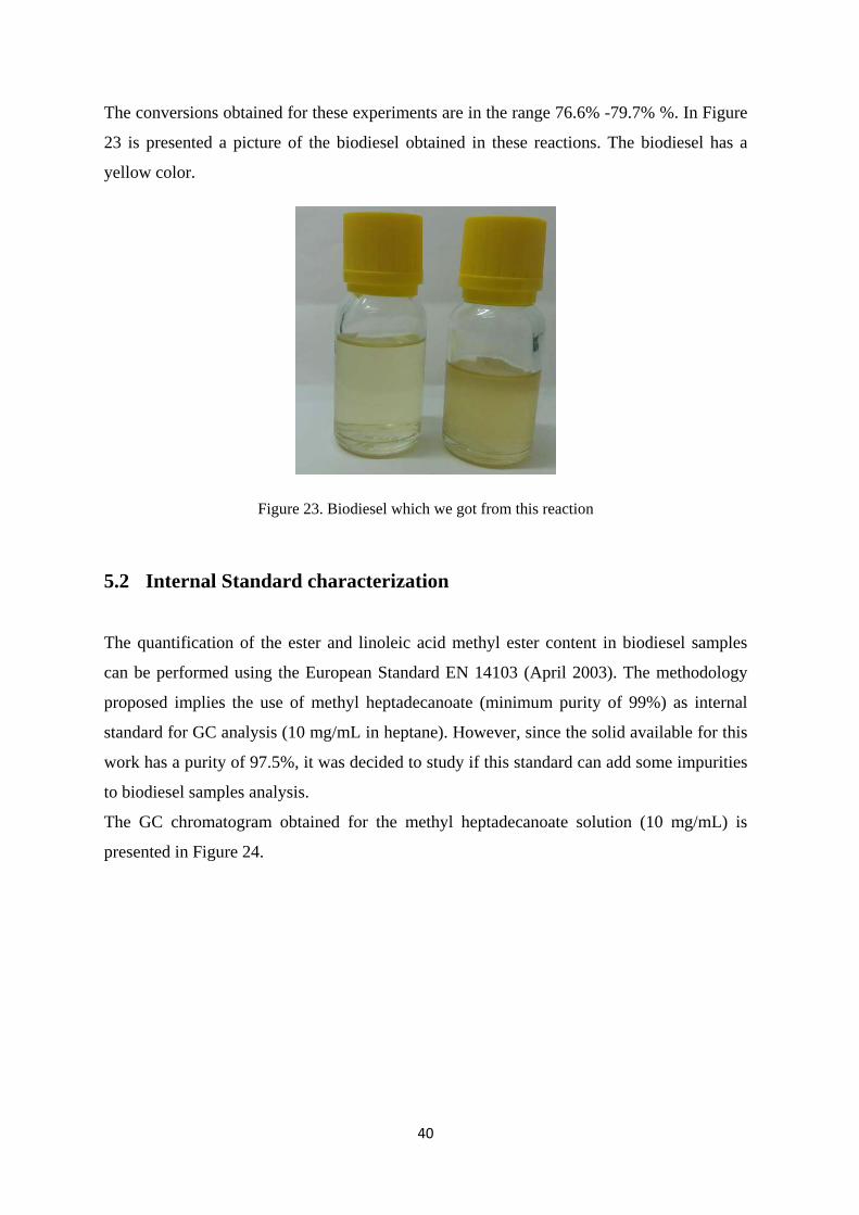
40
The conversions obtained for these experiments are in the range 76.6% -79.7% %. In Figure
23 is presented a picture of the biodiesel obtained in these reactions. The biodiesel has a
yellow color.
Figure 23. Biodiesel which we got from this reaction
5.2 Internal Standard characterization
The quantification of the ester and linoleic acid methyl ester content in biodiesel samples
can be performed using the European Standard EN 14103 (April 2003). The methodology
proposed implies the use of methyl heptadecanoate (minimum purity of 99%) as internal
standard for GC analysis (10 mg/mL in heptane). However, since the solid available for this
work has a purity of 97.5%, it was decided to study if this standard can add some impurities
to biodiesel samples analysis.
The GC chromatogram obtained for the methyl heptadecanoate solution (10 mg/mL) is
presented in Figure 24.

41
Figure 24. GC chromatogram obtained for the methyl heptadecanoate solution (10 mg/mL). Both figures represent the same chromatogram (right figure used to visual identify the main peaks in
baseline).
From the right amplified chromatogram we can see three main impurities (peak area above
10000) present in the standard solution. With this analysis it was possible to obtain the
purity for the internal standard solution of 99.2% (higher than the value indicated in the
label of the reagent flask, ≥97.5%). This value was obtained by the ratio of the area of
methyl heptadecanoate and the total area of all peaks having a minimum area of integration
of 10000. This integration parameter as well as a signal to noise ratio of 1:5 was used for all
the biodiesel samples analysis, presented in the following sections. It was decided not to
consider all these impurities added by the internal standard in the quantification process for
all the samples obtained in the recovery studies. The retention times of these non- identified
(NI) peaks are 43.6, 45.3 and 77.4 min, for 1, 2 and 3, respectively.
5.2.1 Complete esterification of Oleic Acid using sulfuric acid
Other experimental task was the characterization of the oleic acid used as organic raw
material for the esterification reaction to produce biodiesel. This reagent was available with
a purity of ≥90% and it was decided to measure the maximum quantity of methyl ester
obtained by a “complete” esterification using sulfuric acid as catalyst.
The GC analysis of biodiesel sample obtained by esterification with sulfuric acid and
analyzed using the internal standard methodology is presented in Figure 25.
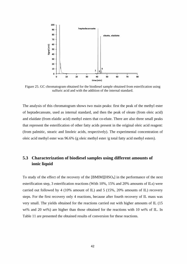
42
Figure 25. GC chromatogram obtained for the biodiesel sample obtained from esterification using
sulfuric acid and with the addition of the internal standard.
The analysis of this chromatogram shows two main peaks: first the peak of the methyl ester
of heptadecanoate, used as internal standard, and then the peak of oleate (from oleic acid)
and elaidate (from elaidic acid) methyl esters that co-elute. There are also three small peaks
that represent the esterification of other fatty acids present in the original oleic acid reagent:
(from palmitic, stearic and linoleic acids, respectively). The experimental concentration of
oleic acid methyl ester was 96.6% (g oleic methyl ester /g total fatty acid methyl esters).
5.3 Characterization of biodiesel samples using different amounts of ionic liquid
To study of the effect of the recovery of the [BMIM][HSO4] in the performance of the next
esterification step, 3 esterification reactions (With 10%, 15% and 20% amounts of ILs) were
carried out followed by 4 (10% amount of IL) and 5 (15%, 20% amounts of IL) recovery
steps. For the first recovery only 4 reactions, because after fourth recovery of IL mass was
very small. The yields obtained for the reactions carried out with higher amounts of IL (15
wt% and 20 wt%) are higher than those obtained for the reactions with 10 wt% of IL. In
Table 11 are presented the obtained results of conversion for these reactions.
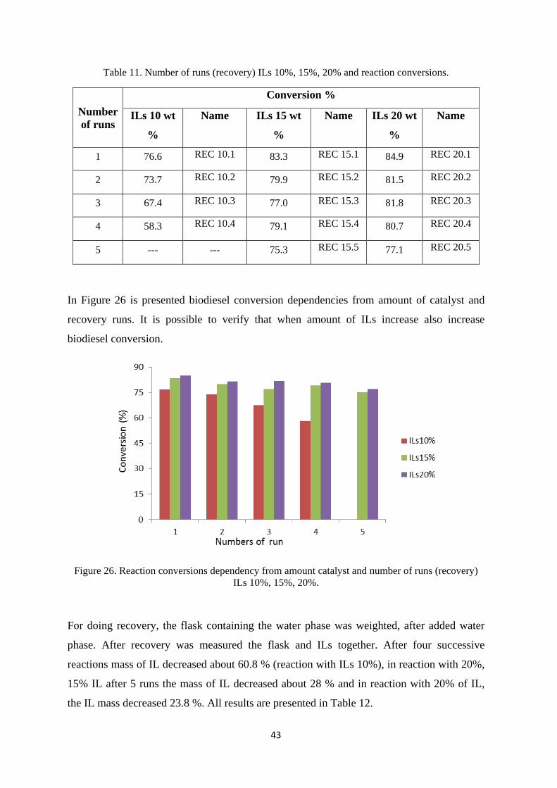
43
Table 11. Number of runs (recovery) ILs 10%, 15%, 20% and reaction conversions.
Number of runs
Conversion %
ILs 10 wt
%
Name ILs 15 wt
%
Name ILs 20 wt
%
Name
1 76.6 REC 10.1 83.3 REC 15.1 84.9 REC 20.1
2 73.7 REC 10.2 79.9 REC 15.2 81.5 REC 20.2
3 67.4 REC 10.3 77.0 REC 15.3 81.8 REC 20.3
4 58.3 REC 10.4 79.1 REC 15.4 80.7 REC 20.4
5 --- --- 75.3 REC 15.5 77.1 REC 20.5
In Figure 26 is presented biodiesel conversion dependencies from amount of catalyst and
recovery runs. It is possible to verify that when amount of ILs increase also increase
biodiesel conversion.
Figure 26. Reaction conversions dependency from amount catalyst and number of runs (recovery) ILs 10%, 15%, 20%.
For doing recovery, the flask containing the water phase was weighted, after added water
phase. After recovery was measured the flask and ILs together. After four successive
reactions mass of IL decreased about 60.8 % (reaction with ILs 10%), in reaction with 20%,
15% IL after 5 runs the mass of IL decreased about 28 % and in reaction with 20% of IL,
the IL mass decreased 23.8 %. All results are presented in Table 12.

44
Table 12. ILs mass after from recovery runs
Number of runs
IL mass (g)
(10 wt% IL)
IL mass (g)
(15 wt% IL) IL mass (g)
(20 wt% IL)
1 1.156 1.7383 2.2312
2 1.156* 1.7383* 2.2312*
3 0.804 1.7383* 2.2312*
4 0.453 1.4291 1.8136
5 --- 1.2500 1.6690
*After recovery mass of IL was a higher and was considered that all initial mass in recovery sample.
In Figure 27 is shown ILs mass (g) dependency from number of runs (recovery) for IL
10%, 15%, 20%. When numbers of run increases, mass of ILs decreases.
Figure 27. ILs mass (g) dependency from numbers of run (recovery) ILs 10%, 15%, 20%.
5.3.1 Ratio of Ionic Liquid to Oleic Acid of 10%
The GC chromatograms for the analysis of all the biodiesel obtained using a 10 wt% of
ionic liquid is presented in Figure 28.

45
Figure 28. GC chromatograms obtained for the biodiesel samples obtained for 10% IL, from
esterification after 4 recovery steps (REC 10.1 to 10.4).
The experimental concentration of FAME content in these samples was obtained using the
same methodology explained before (EN 14103-2003). The experimental concentrations (g
FAMEs/g biodiesel) values are 61.2%, 49.4%, 43.5% and 56.2%. Concentration of REC
10.4 was a higher then Rec 10.2 and Rec 10.3: probably it was experimental error.
5.3.2 Ratio of Ionic Liquid to Oleic Acid of 15%
The GC chromatograms for the analysis of all the recovered biodiesel samples obtained
using a 15% of ionic liquid are presented in Figure 29.

46
Figure 29. GC chromatograms obtained for the biodiesel samples obtained for 15% IL, from esterification after 4 recovery steps (REC 15.1 to 15.5).
The experimental concentration of FAME content in these samples was obtained using the
same methodology explained before (EN 14103-2003). The experimental concentrations (g
FAMEs/g biodiesel) values are 63.1%, 59.0%, 55.0%, 95.6% and 44.5%. The outlier value
of 95.6% (REC 15.4) it was considered has being due to an experimental error.

47
5.3.3 Ratio of Ionic Liquid to Oleic Acid of 20%
The GC chromatograms for the analysis of all the recovered biodiesel samples obtained
using a 20% of ionic liquid are presented in Figure 30.
Figure 30. GC chromatograms obtained for the biodiesel samples obtained for 20% IL, from esterification after 4 recovery steps (REC 20.1 to 20.5).
The experimental concentration of FAME content in these samples was obtained using the
same methodology explained before (EN 14103-2003). The experimental concentrations (g
FAMEs/g biodiesel) values are 64.7%, 60.5%, 62.6%, 59.9% and 56.5%.

48
5.4 ILs analysis by UV-VIS
Ionic liquids can be transparent in the near-ultraviolet and visible spectral regions, in
contrast to many other polar organic solvents. This makes that ionic liquids are very
interesting solvents for spectroscopic measurements on dissolved metal salts and metal
complexes. For the quality control of ionic liquids, UV/VIS spectrophotometry was applied.
It is an efficient method [Nockemann- 2005]. The effect of the recovery steps in the quality
of the ionic liquid was studied by UV-VIS spectroscopy. The spectrum of original IL and
the ILs recovered after the final esterification reaction, for each %IL is presented in Figure
31. The original ILs has a yellow colour, but the recovery ILs sample has a little bit dark
colour. In Figure 31, the absorption spectra of samples of the ionic liquid [BMIM][HSO4]
are shown. The spectra were recorded in a 1 cm quartz cell. The absorption spectrum of the
original ionic liquid (red, solid line) shows an absorption maximum around 260 nm.
Figure 31. UV-Vis spectrum obtained for original and the recovered ILs obtained for different amount of ILs (10, 15 and 20%).
The original ionic liquid [BMIM][HSO4] 0.11 absorbance threshold shifts for the original
ILs sample from 200 nm to about 260 nm, the spectra of the recovered not differ from each
other’s and show absorption bands at for ILs (REC20 ) 200 nm to 250 nm ,for ILs (REC15)
200 nm to 264, for ILs (REC10) 200nm to about 255. Spectroscopic results prove the
[BMIM][HSO4] after recovery retained stable catalytic performance.

49
5.5 ILs analysis by FTIR
The effect of the recovery steps in the quality of the ionic liquid was studied by Fourier
Transform Infra-Red (FTIR) spectroscopy.
The molecular formula for the ionic liquid, 1-Butyl-3-methylimidazolium hydrogen sulfate
is [BMIM][HSO4]. Figure 32 shows the structural formula of the sample.
Figure 32. Formula 1-Butyl-3-methylimidazolium hydrogen sulfate.
The spectrum of original IL, methanol and the ILs recovered after the final esterification
reaction, for each %IL is presented in Figures 33 to 36. It is commonly acknowledged that
the characteristic absorption peaks of [BMIM][HSO4] appear at 3148 cm-1 , 3101 cm-1 , 2962
cm-1 , 2869 cm-1 , 1566 cm-1 , 1464 cm-1 , 1220 cm-1 , 1160 cm-1 , 1030 cm-1 , 835 cm-1 , 755
cm-1. And for methanol 555 cm-1.
Figure 33. FTIR spectrum obtained for original IL and methanol.

50
Table 13 is based on the results presented in Figure 33. This table presents the functional
groups that can be identified in the ionic liquid according to the peaks shown in the
spectrum.
Table 13. Functional group of the components of original IL [Colthup et al., 2009]
Wavelength cm-1 Functional group Molecular motion
755 1. Aromatics 1. C-H bend (meta) ~690
835
1. alkenes
2. sulfones
3. amines
1. C-H bend (disubstituted -1,1) ~890
2. S-O bend 900-800
3.NO2 bend 900-800
1030, 1160,1200
1. ketones
2. amines
3. sulfones
1. C-C stretch 1300-1100
2. C-N stretch (alkyl) 1200-1025
3. SO3 symmetric deformation 1100-1000
1160 1. alcohols
2. ketones
1. C-O stretch 1260-1000
2. C-C stretch 1300-1100
1464 1.alkenes
2. sulfones
1. CH2 bend ~1465
2. SO2 asymmetric stretch 1450-1100
1566 1.amines 1. N-H bend 1640-1500
2869, 2962,
3101, 3148
1.carboxylic acid
2. alkenes
1. O-H stretch 3400-2400
2. CH2 bend 3250-2700
Figure 34 of ionic liquid REC4 presented peaks of SO3 at 1013 and 1046 cm−1, which
correspond to symmetric stretching. The strong adsorption peaks at 3107 cm-1, 1644, 2962
cm-1 were assigned to the C–H, C = C ring stretching vibration of benzylamine.

51
Figure 34. FTIR spectrum obtained for original IL 10% (REC4).
The bands at 1013, 1046 cm-1 were assigned to the S = O asymmetric and symmetric
stretching vibrations of the –SO3H group. Table 14 presents the functional groups of ionic
liquid according the peak from Figure 34.
Table 14. Functional group of the components of IL 10% (REC4) [Colthup et al., 2009]
Wavelength cm-1 Functional group Molecular motion
748 1. Aromatics 1. C-H bend (meta) ~690
850
1. alkenes
2. sulfones
3. amines
1. C-H bend (disubstituted -1,1) ~890
2. S-O bend 900-800
3.NO2 bend 900-800
1013,1046
1. ketones
2. amines
3. sulfones
1. C-C stretch 1300-1100
2. C-N stretch (alkyl) 1200-1025
3. SO3 symmetric deformation 1100-1000
1644 1.amines 1. N-H bend 1640-1500
2871, 2962
3107, 3152, 3440
1.carboxylic acid
2. alkenes
1. O-H stretch 3400-2400
2. CH2 bend 3250-2700
In Figure 35 we can see that there are a new peaks present at 3102 cm-1 and 2856 cm-1, due
to the OH of an alcohol or carboxylic acid, in our case could be due to a contamination of
biodiesel sample with methanol. It is possible to see also new peaks at 1738 cm-1 and 1712
cm-1 can be alkenes group.

52
Figure 35. FTIR spectrum obtained for original IL 15% (REC5).
All characteristic absorption peaks of IL 15 % (REC 5) appear at 3102 cm-1, 2922 cm-1 ,
2856 cm-1, 1738 cm-1, 1712 cm-1, 1571 cm-1, 1458 cm-1, 1047 cm-1, 1009 cm-1, 848 cm-1 ,
748 cm-1 . All functional groups of the components of IL 15 % (REC 5) are shown in Table 15.
Table 15. Functional groups of the components of IL 15% (REC5) [Colthup et al., 2009]
Wavelength cm-1 Functional group Molecular motion
748 1. Aromatics 1. C-H bend (meta) ~690
848
1. alkenes
2. sulfones
3. amines
1. C-H bend (disubstituted -1,1) ~890
2. S-O bend 900-800
3.NO2 bend 900-800
1009, 1047,
1172,
1. ketones
2. amines
3. sulfones
1. C-C stretch 1300-1100
2. C-N stretch (alkyl) 1200-1025
3. SO3 symmetric deformation 1100-1000
1160 1. alcohols
2. ketones
1. C-O stretch 1260-1000
2. C-C stretch 1300-1100
1458 1.alkenes
2. sulfones
1. CH2 bend ~1465
2. SO2 asymmetric stretch 1450-1100
1738, 1712 1.alkenes 1.CH2 medium 1850-1750
2856, 2922, 3102 1.carboxylic acid
2. alkenes
1. O-H stretch 3400-2400
2. CH2 bend 3250-2700

53
The characteristic absorption peaks of IL 20 % (REC 5) appear at 3450 cm-1, 3100 cm-1 ,
2960 cm-1, 2870 cm-1, 1568 cm-1, 1466 cm-1, 1215 cm-1, 1163 cm-1, 1038 cm-1, 1008 cm-1.
The spectra showed a new peak present at 3440 cm-1, due to the OH of an alcohol or
carboxylic acid.
Figure 36. FTIR spectrum obtained for original IL 20% (REC5).
Figure 36 also shows the strong peak 1163 cm -1, the same peak we can see in Original IL
spectra. It is can be alcohols or ketones. In Table 16 shown functional group of the
components of IL 20% (REC5).
Table 16. Functional group of the components of IL 20% (REC5) [Colthup et al., 2009].
Wavelength cm-1 Functional group Molecular motion
1008, 1038, 1163,
1215
1. alcohols
2. ketones
1. C-O stretch 1260-1000
2. C-C stretch 1300-1100
1466 1.alkenes
2. sulfones
1. CH2 bend ~1465
2. SO2 asymmetric stretch 1450-1100
1568 1.amines 1. N-H bend 1640-1500
2870, 2960,
3100, 3450
1.carboxylic acid
2. alkenes
1. O-H stretch 3400-2400
2. CH2 bend 3250-2700

54
6. Conclusions and Future work
The effect of different reaction for biodiesel production was studied using different ionic
liquid as a catalyst. The study of the esterification of oleic acid with ionic liquids was
carried out for obtaining high yield biodiesel production. For analyzing the biodiesel
samples was used a GC.
In this dissertation different esterification reactions were carried out with different kind of
ILs. The conversion varied between an 18 -88 %. For the study we selected [BMIM]
[HSO4] ionic liquid. The reaction yield was found to be 76.6% to 10% IL, 83.3% to 15% IL
and 84.8% to 20% IL. These yields decreased to 58.2% (10% IL) with 4 cycles of recycling,
75.2% (15% IL) with 5 cycles of recycling and 77.1% (20% IL) with 5 cycles of recycling.
In this work the FAME content was calculated: values of around 50-60% of FAMEs / g
biodiesel sample. Another 40-50% could be in the organic phase (as acids) or in the aqueous
phase.
For analyzing the ILs was used UV-VIS and FTIR. And found that it retained stable
catalytic performance after recovery.
Future work
In this thesis work, there are some further important researches that need to study. In this
dissertation esterification reaction, were carried out for biodiesel production, using methanol
and oleic acid and ILs as a catalyst. Though, in the future experiments will be testing other
acids for biodiesel production.
The IL ([BMIM] [HSO4]) recovery was. Catalyst recovery was a 5 time (5 recycling).
However, in the future experiments will be for improving conditions of recovery: heating
time and temperature. Improve the recovery runs to increase 6-8 times. And also in the
future experiments will be testing other ILs for recovery.
In this work used GC analysis for biodiesel sample, and UV-VIS and FTIR for ILs analysis.
But in future have to be doing the FTIR analysis for oleic acid. And use more methods for
analysis.

55
References
• Abbaspour-Gilandeha E., Azim S. C. “Brønsted acidic ionic liquid ([BMIM]HSO4)
as an efficient catalysts for the one-pot synthesis of 2H-indazolo[2,1-b] phthalazine-
trione derivatives” , Iranian Journal of Catalysis: 2014, 4(3): 175-180
• Aghabarari B., Nasim D., Mehran G., Sajad G. A., Ebrahim R., M.V. Martinez-
Huerta “Esterification of fatty acids by new ionic liquids as acid catalysts”, Journal
of the Taiwan Institute of Chemical Engineers, 2014; 45: 431-435
• Ahmia A.C., Danane, Bessah F. R., Boumesbah I., “Raw material for biodiesel
production. Valorization of used edible oil”, Revue des Energies Renouvelables,
2014; 17: 335-343 [3] Biodiesel handling and use guide, National Renewable Energy
Laboratory, 4th edition, 2009
• Alimova I., "Production of Biodiesel through Esterification Catalysed by Ionic
Liquids" Master Thesis, Instituto Politécnico de Bragança, Portugal, 2016
• Alimova I., “Production of Biodiesel through Esterification Catalysed by Ionic
Liquids”, Master Thesis, Polytechnic Institute of Bragança, 2015
• Andreani L., Rocha J. D., “Use of Ionic Liquids in biodiesel production: A Review”,
Brazilian Journal of Chemical Engineering, 2012: 29: 1-13
• Azad A. K., Ameer Uddin S. M., Alam M. M., “Experimental study of DI diesel
engine performance using biodiesel blends with kerosene”, International Journal of
Energy and Environment, 2013; 4: 265-278
• Basa L.T., ”Ionic Liquids: Solvation Characteristics and Cellulose Dissolution”,
Master Thesis, University of Toledo, 2010
• Biodiesel Handling and Use Guide, Energy Efficiency and Renewable Energy, Fifth
Edition, 2016
• Biodiesel Instructor Guide, Biorenewables Education Laboratory Summer Academy,
2011
• Bollin P. M., “The Production of Fatty Acid Methyl Esters in Lewis Acidic Ionic
Liquids”, University of Toledo, Spain, 2011
• CP-3800 GC Getting Started Manual, 1999
• Earle M. J., Plechkova N. V., Seddon K. R., “Green synthesis of biodiesel using
ionic liquids”, Pure and Applied Chemistry, 2009; 81: 2045–2057

56
• Emelyanenko V. N., Verevkin, Heintz S. P. A., “Imidazolium-Based Ionic Liquids.
1- Methyl Imidazolium Nitrate: Thermochemical Measurements and Ab Initio
Calculations”, The Journal of Physical Chemistry B, 2009; 113: 9871-9876
• EN 14103 “Fat and oil derivatives - Fatty Acid Methyl Esters (FAME)
Determination of ester and linolenic acid methyl ester contents”, 2003
• Fang Z., Smith Jr. R.L., Qi, X., (Eds), in “Production of Biofuels and Chemicals
with Ionic Liquids”, Springer Science Business Media, Dordrecht, 2014
• Fauzi A. H. M. , Amin N. A. S. “An overview of ionic liquids as solvents in
biodiesel synthesis” Chemical Reaction Engineering Group (CREG), Faculty of
Chemical Engineering, Universiti Teknologi Malaysia, Renewable and Sustainable
Energy Reviews: 2012, 16 :5770–5786
• Fauzi A. H. M., Amin N. A. S., “Optimization of oleic acid esterification catalyzed
by ionic liquid for green biodiesel synthesis”, Energy Conversion and Management:
2013, 76: 818–827
• Fauzi A. H. M., Amin N. A. S., Ramli Mat “Esterification of oleic acid to biodiesel
using magnetic ionic liquid: Multi-objective optimization and kinetic
study”, Applied Energy: 2014, 114: 809-818,
• Feltes M. M. C., Debora , Ninow J.L., Jose Vladimir de Oliveira "An Overview of
Enzyme-Catalyzed Reactions and Alternative Feedstock for Biodiesel Production" ,
Federal University of Santa Catarina, Brazil, 2011
• Freire M.G., Santo L.M.N.B.F., Fernandes A.M., Coutinhoa J.A.P., Marruchoa I.M
" An overview of the mutual solubilities of water–imidazolium-based ionic liquids
systems", 2007, 261: 449–454,
• Garofalo R., “European Biodiesel board”, EBB Presentation, State of Play of
European Biodiesel, 2013
• Guo F., Fang Z., Tian X., Long Y., Jiang L., “One step production of biodiesel from
Jatropha oil with high-acid value in ionic liquids” , Bioresource Technology Journal,
2011; 102: 6469-6472
• Hassan M. H., Kalam M. A., “An overview of biofuel as a renewable energy source:
development and challenges”, 2013; 56: 39-53
• Hoekman S. K., Broch A., Robbins C., Ceniceros E., Natarajan M., “Review of
biodiesel composition, properties, and specifications”, Renewable and sustainable
Energy Reviews, 2012; 16: 143-169
57
• http://articles.extension.org/pages/26968/energy-life-cycle-analysis-of-biodiesel
20.11.2016
• Huddleston J. G., Visser A. E., Reichert W. M., Willauer H. D., Broker G. A.,
Rogers R. D., “Characterization and comparison of hydrophilic and hydrophobic
room temperature ionic liquids incorporating the imidazolium cation”, Green
Chemistry 2001; 3: 156-164
• Johnson F. X., Pacini H., Smeets E., “Transformations in EU biofuels markets under
the Renewable Energy Directive and the implications for land use, trade and
forests”, Occasional Paper 78. CIFOR, Bogor, Indonesia, 2012
• Mai N. L., Ahn K., Yoon-Mo Koo, “Methods for recovery of ionic liquids—A
review ” , Process Biochemistry: 2014, 49: 872–881
• Muhammada N., Elsheikh Y. A., Ibrahim M., Mutalib A., Bazmi A. A., Khan R. A.,
Rafiq S., Manc Z., Khan I., “An overview of the role of ionic liquids in biodiesel
reactions”, Journal of Industrial and Engineering Chemistry, 2015; 21: 1-10
• Nockemann P., Binnemans K., Driesen K., “Purification of imidazolium ionic
liquids for spectroscopic applications " Katholieke Universiteit Leuven, Department
of Chemistry, Celestijnenlaan 200F, B-3001 Leuven, Belgium, Chemical Physics
Letters, 2005; 415:131–136
• Pacini H., Sanches-Pereira A., Durleva M., Kane M., Bhutani M., “The emerging
biofuels market: Regulatory, Trade and Development Implications”, United Nations
Conference on Trade and Development, 2014
• Phillips S. , Bob Flach, Sabine Lieberz, Marcela Rondon, Barry Williams and
Candice Wilson “Biofuels Annual”, “EU Biofuels Annual 2016”, 2016; NL6021
• Ren Q., Zuo T., Pan J., Chen C., Weimin Li, “Preparation of Biodiesel from
Soybean Catalyzed by Basic Ionic Liquids [Hnmm]OH”, Material-Open Access
Materials Science Journal, 2014; 7: 8012-8023
• Renewable Energy Progress Report”, Report from the commission to the European
parliament, the council, the European economic and social committee and the
committee of the regions, Brussels, 01.02.2017
• Renewable Energy Progress Report”, Report from the commission to the European
parliament, the council, the European economic and social committee and the
committee of the regions, Brussels, 01.02.2017

58
• Romano S. D., Sorichetti P. A. (Eds) “Dielectric Spectroscopy in Biodiesel
Production and Characterization”, Springer-Verlag London Limited 2011, Chapter 2,
7-27
• Shukla M., Saha S., “A Comparative Study of Piperidinium and Imidazolium Based
Ionic Liquids: Thermal, Spectroscopic and Theoretical Studies", in "Ionic Liquids -
New Aspects for the Future”, (Jun-ichi Kadokawa, ed.) Chapter 3, 2013
• Slade R., Bauen A. “Micro-algae cultivation for biofuels: Cost, energy balance,
environmental impacts and future prospects”, Biomass and Bioenergy, 2013; 53: 29-
38
• Specification sheet ‘Varian Cary 50 UV-Vis Spectrophotometer’, SI-0821
,Australia, 2007
• Stojanovic A., Morgenbesser C., Kogelnig D., Krachler R., Keppler B. K.,
“Quaternary Ammonium and Phosphonium Ionic Liquids in Chemical and
Environmental Engineering’, in "Ionic Liquids: Theory, Properties, New
Approaches", (Alexander Kokorin, ed.), Chapter 26, 2011
• Supelco Bulletin 907-Sigma-Aldrich,
• Taimur A., “Synthesis of Biodiesel from Triglyceride oil”, Master Thesis, University
of Stavanger, Norway, 2011
• Tat M.E., Van Gerpen J. H., “Physical Properties and Composition Detection of
Biodiesel-diesel Fuel Blends”, The society for engineering in agricultural, food and
biological systems, An ASAE Meeting Presentation, 2002; 2-11
• Ullah Z., Bustam M. A., Man Z., “Biodiesel production from waste cooking oil by
acidic ionic liquid as a catalyst”, Renewable Energy, 2015; 77: 521-526
• Ved K., Padam, K. “Study of Physical and Chemical Properties of Biodiesel from
Sorghum Oil”, Research Journal of Chemical Sciences, 2013; 3: 64-68
• Visser E., Huddleston L. G., Rechert J. M., Swatloski R. P., Rogers R. D..
“Hydrophobic n-Alkyl-N-isoquinolinium Salts: Ionic Liquids and Low Melting
Solids”, ACS Symposium Series, 2009; 975: 362-380
• Woon S. O.,”Synthesis and applications of imidazolium-based ionic liquids and their
polymer derivatives”, Missouri University of Science and Technology, Doctoral
Dissertation, Paper 1958, 2012

59
• Xu Wei , Ge Xiao-dong , Yan Xiu-hua , Shao Rong “Optimization of methyl
ricinoleate synthesis with ionic liquids as catalysts using the response surface
methodology”, Chemical Engineering Journal: 2015, 275: 63–70
• Zhang W., Lijun H., Gu Y., Jiang S., “Effect of ionic liquids as mobile phase
additivetes on retention of catecholamines in reversed-phase high-performance
liquid chromatography”, Analytical Letters, 2007; 36: 827-838
• Zhao H., Baker G. A. - Ionic liquids and deep eutectic solvents for biodiesel
synthesis: a review”, J. Chem. Technol. Biotechnol., 2013; 88: 3–12
• http://ec.europa.eu/eurostat/statisticsexplained/index.php/Energy_from_renewable_s
our 25.11.2016
• http://www.biodieselmagazine.com/articles/3103/eu-adopts-10-percent-
biofuelsmandate/ 30.11.2016
• http://www.conserve-energy-future.com/Advantages_Disadvantages_Biodiesel.php
23.11.2016
• http://www.sigmaaldrich.com/technical-documents/articles/chemfiles/ionic-
liquids0.html 30.11.2016
• http://www.renewableenergyworld.com/bioenergy/tech/biofuels.html 10.01.2017
• http://study.com/academy/lesson/esterification-definition-process-
reactions.html#transcriptHeader 20.06.2017
• http://www.filtsep.com/view/30922/chemicals-pervaporation-and-vapour-
permeation-processes-meet-specialist-needs/ 20.06.2017
• http://dartonrefuel.com/biodiesel.php/ 21.11.2016
• http://www.ebb-eu.org/stats.php 26.11.2016
• http://bioethanol.ru/biodiesel/technology/ 15.01.2017
• http://www.biofuelstp.eu/factsheets/fame-fact-sheet.pdf 25.12.2016

60
Appendix
Appendix A Titration Values
Appendix A1 different Ionic liquids
Table A1. Titration data and obtained acid number and biodiesel yield
ILs wt 10%, AO/MeOH 1/10
Initial acidity of AO
Acidity mg KOH/g
Conversion % Concentration of
KOH/MeOH solution
[BMIM][HSO4] 183.7482 77.6827 57.7233 0.07859
[BMIM][MeSO4] 183.7482 42.3879 79.4544 0.07859
[MIM][HSO4] 183.7482 21.1044 88.5145 0.07859
C9H18N2O3S 183.7482 149.9827 18.376 0.07859
C14H33NO4S 183.7482 155.4739 15.3875 0.07859
Appendix A2 [BMIM][HSO4] Ionic liquids
Table A2. Titration data and obtained acid number and biodiesel yield
ILs wt 10%, AO/MeOH 1/10
Initial acidity of AO
Acidity (mg KOH/biodiesel)
Conversion %
Concentration of KOH/MeOH
solution
[BMIM][HSO4] 183.7482 41.0333 79.68 0.07859
[BMIM][HSO4] 183.7482 39.952 77.66 0.07859
[BMIM][HSO4] 183.7482 42.9217 76.64 0.07859
[BMIM][HSO4] 183.7482 48.2603 78.25 0.07859
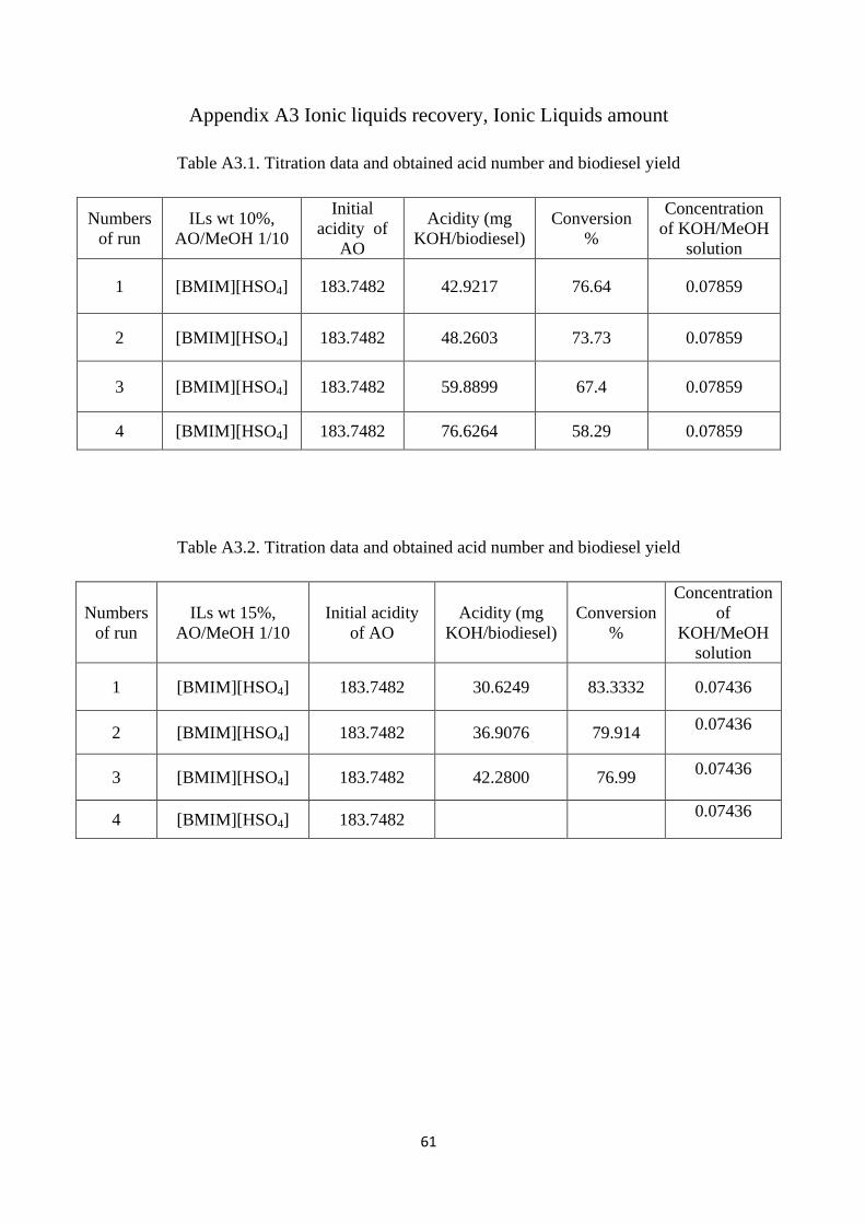
61
Appendix A3 Ionic liquids recovery, Ionic Liquids amount
Table A3.1. Titration data and obtained acid number and biodiesel yield
Numbers of run
ILs wt 10%, AO/MeOH 1/10
Initial acidity of
AO
Acidity (mg KOH/biodiesel)
Conversion %
Concentration of KOH/MeOH
solution
1 [BMIM][HSO4] 183.7482 42.9217 76.64 0.07859
2 [BMIM][HSO4] 183.7482 48.2603 73.73 0.07859
3 [BMIM][HSO4] 183.7482 59.8899 67.4 0.07859
4 [BMIM][HSO4] 183.7482 76.6264 58.29 0.07859
Table A3.2. Titration data and obtained acid number and biodiesel yield
Numbers of run
ILs wt 15%, AO/MeOH 1/10
Initial acidity of AO
Acidity (mg KOH/biodiesel)
Conversion %
Concentration of
KOH/MeOH solution
1 [BMIM][HSO4] 183.7482 30.6249 83.3332 0.07436
2 [BMIM][HSO4] 183.7482 36.9076 79.914 0.07436
3 [BMIM][HSO4] 183.7482 42.2800 76.99 0.07436
4 [BMIM][HSO4] 183.7482 0.07436
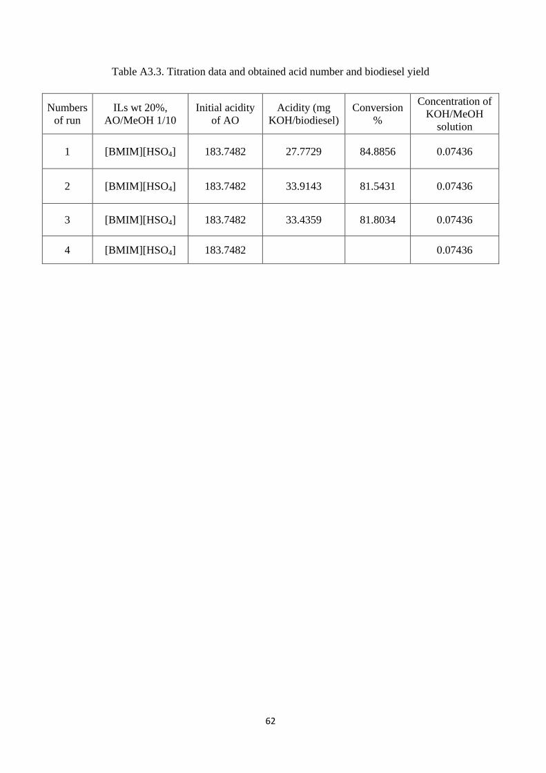
62
Table A3.3. Titration data and obtained acid number and biodiesel yield
Numbers of run
ILs wt 20%, AO/MeOH 1/10
Initial acidity of AO
Acidity (mg KOH/biodiesel)
Conversion %
Concentration of KOH/MeOH
solution
1 [BMIM][HSO4] 183.7482 27.7729 84.8856 0.07436
2 [BMIM][HSO4] 183.7482 33.9143 81.5431 0.07436
3 [BMIM][HSO4] 183.7482 33.4359 81.8034 0.07436
4 [BMIM][HSO4] 183.7482 0.07436