Embed Size (px)
Citation preview

ARTICLESPUBLISHED ONLINE: 7 MARCH 2016 | DOI: 10.1038/NMAT4570
Biodegradable sca�old with built-in vasculaturefor organ-on-a-chip engineering and directsurgical anastomosisBoyang Zhang1,2, Miles Montgomery1,2, M. Dean Chamberlain2, Shinichiro Ogawa3,Anastasia Korolj1,2, Aric Pahnke1,2, Laura A. Wells2, Stéphane Massé4, Jihye Kim5, Lewis Reis2,Abdul Momen6, Sara S. Nunes2,6,7, Aaron R. Wheeler2,5, Kumaraswamy Nanthakumar4,Gordon Keller3, Michael V. Sefton1,2 and Milica Radisic1,2,6,7*
We report the fabrication of a sca�old (hereafter referred to as AngioChip) that supports the assembly of parenchymal cellson a mechanically tunable matrix surrounding a perfusable, branched, three-dimensional microchannel network coated withendothelial cells. The design of AngioChip decouples the material choices for the engineered vessel network and for cellseeding in the parenchyma, enabling extensive remodelling while maintaining an open-vessel lumen. The incorporation ofnanopores and micro-holes in the vessel walls enhances permeability, and permits intercellular crosstalk and extravasation ofmonocytes and endothelial cells on biomolecular stimulation. We also show that vascularized hepatic tissues and cardiactissues engineered by using AngioChips process clinically relevant drugs delivered through the vasculature, and thatmillimetre-thick cardiac tissues can be engineered in a scalable manner. Moreover, we demonstrate that AngioChip cardiactissues implantedwith direct surgical anastomosis to the femoral vessels of rat hindlimbs establish immediate blood perfusion.
Recapitulating vascular interfaces of different organs in threedimensions is critical in both organ-on-a-chip1–3 and tissueengineering applications4–8. Three-dimensional (3D) micro-
tissues composed of parenchymal cells have often been studiedin the absence of vasculature9–11, whereas vasculature-on-a-chiphas primarily been studied separately from the parenchymalcells12–14. A similar vascularization challenge has been experiencedon the macroscale. Numerous tissue types have been successfullyengineered in vitro, but clinical translation has been achieved onlyfor thin tissues or those with a low metabolic demand (for example,skin, cartilage and bladder)15. Large solid tissues (for example,myocardium and liver) are highly sensitive to oxygen levels andbecome vulnerable within hours without oxygen supply15–17. Thesetissues would greatly benefit from rapid vascularization in vitro anddirect vascular integration in vivo. Although elegant approacheshave been described that enable anastomosis of oriented engineeredcapillaries to the host vasculature with perfusion several daysafter implantation18, direct surgical anastomosis with immediateperfusion of vascularized tissues has been demonstrated only usingvascular explants19,20, requiring multiple surgeries to harvest thevascular bed.
Vascular networks can be engineeredwith subtractive fabricationby embedding a sacrificial carbohydrate–glass lattice3,21, PluronicF127 (ref. 3), dry alginate fibres22, or gelatin23 in hydrogels. However,the soft hydrogel provides only temporary structural support forthe fragile hollow network and does not permit extensive tissueremodelling21, which inevitably alters the hydrogel structure and
collapses the embedded network. Synthetic biodegradable polymerscould provide sufficient structural support to the engineered vessels,but their low permeability prevents biomolecule exchange and cellmigration between the vessels and the parenchymal space24–26.
To accommodate these two opposing material criteria, wecreated AngioChip, a stable biodegradable scaffold with a built-inbranching microchannel network featuring two unique advancesrealized by our new 3D stamping technique. First, the syntheticbuilt-in vascular walls were thin and flexible, yet strong enoughto mechanically support a perfusable vasculature in a contractingtissue and enable direct surgical anastomosis. Second, to allowefficient molecular exchange and cell migration, nanoporesand micro-holes were incorporated into the vascular walls. Byestablishing a stable, permeable, vessel network within AngioChips,we were liberated from material constraints, enabling the use ofvarious extracellular matrices (ECMs) with cells in the parenchymalspace and tissue remodelling. The AngioChip parenchymal spacestructure was also fine-tuned to mimic the anisotropy of nativetissues (for example, myocardium), traditionally difficult to achievewith a homogeneous hydrogel. On the basis of this methodology,we created functional and vascularized cardiac and hepatic tissues.
AngioChip sca�old with branching interconnected lumenThe AngioChip scaffolds were constructed using a biodegradableelastomer, poly(octamethylene maleate (anhydride) citrate)(POMaC; Fig. 1)27,28. POMaC was selected because it is ultraviolet-polymerizable, allowing rapid assembly under mild conditions;
1Department of Chemical Engineering and Applied Chemistry, University of Toronto, Toronto, Ontario M5S 3E5, Canada. 2Institute of Biomaterials andBiomedical Engineering, University of Toronto, Toronto, Ontario M5S 3G9, Canada. 3McEwen Center for Regenerative Medicine, Toronto, Ontario M5G 1L7,Canada. 4The Toby Hull Cardiac Fibrillation Management Laboratory, Toronto General Hospital, Toronto, Ontario M5G 2C4, Canada. 5Department ofChemistry, University of Toronto, Toronto, Ontario M5S 3H6, Canada. 6Toronto General Research Institute, University Health Network, Toronto,Ontario M5G 1L7, Canada. 7The Heart and Stroke/Richard Lewar Centre of Excellence, Toronto, Ontario M5G 1L7, Canada. *e-mail: [email protected]
NATUREMATERIALS | VOL 15 | JUNE 2016 | www.nature.com/naturematerials 669
© 2016 Macmillan Publishers Limited. All rights reserved

ARTICLES NATUREMATERIALS DOI: 10.1038/NMAT4570
Polycarbonatebase
PDMSbase
Polycarbonatebody
Cap
Inletwell
Mainwell
Outletwell
(1) Suspend scaffold (2) Seed endothelial cells
(3) Seed parenchymalcells with ECM
(4) Gel compaction/tissue remodelling
a b
d
c
e f g
hi
j
k m
n
Parenchymal cells(parenchymal space)
Endothelialized lumen
Nanopores
AngioChipscaffold Micro-holes
Native ECMs
10080604020
0Mas
s lo
ss (%
)Pore-free Nanoporous
p < 0.01
l
Figure 1 | AngioChip sca�old fabrication and visualization. a, Image of multiple AngioChip sca�olds patterned in parallel on glass slides. b, Image of anAngioChip hepatic tissue, perfused with a colour dye, beside the tip of a ballpoint pen for scale. c, Schematic of the assembly of the bioreactor and theassembly of vascularized tissue. d, Schematic of a part of an AngioChip tissue. e–g, Scanning electron micrographs (SEMs) of a 1D tube (e; scale bars,1.5 mm and 500 µm), a 2D AngioChip sca�old (f; scale bars, 1 mm and 300 µm) and a multi-layer 3D AngioChip sca�old with 20 µm micro-holes (g; scalebars, 1 mm and 400 µm) created using the 3D stamping technique. h, SEM of an AngioChip sca�old with 10 µm micro-holes on the channel walls. Scale bar,200 µm. i,j, SEMs of the 3D lattice matrix in between the microchannels (i; scale bar, 100 µm) and the cross-section of a 10 µm micro-hole on the channelwall (j; scale bar, 50 µm). Red arrows point to the micro-holes. k,l, SEMs of the AngioChip sca�olds with 20 µm micro-holes on the top and side walls of themicrochannels. Red arrows point to the micro-holes on the top and side walls. Scale bars, 400 µm (k), and 100 µm (l). m, Mass loss in one day fromporogen leaching for pore-free and nanoporous AngioChip sca�olds (average± s.d., n=3). Pore-free and nanoporous corresponds to sca�olds fabricatedwithout or with the use of porogen, respectively. n, SEM of the surface of an AngioChip sca�old after porogen leaching. Scale bar, 500 nm.
biodegrades by hydrolysis27 (Supplementary Figs 1 and 2); andis more elastic than FDA (Food and Drug Administration)-approved polyesters29. Citric acid-based elastomers also have lowthrombogenicity30,31. Thin POMaC sheets were pre-patterned, ina scalable manner (Fig. 1a), under ultraviolet illumination andstamped onto each other, layer by layer with precise alignment downto severalmicrometres, to form complex suspendedmicrostructuresand internal cavities. POMaC exhibited temporary and differential
adhesion to glass (strong) and polydimethylsiloxane (PDMS; weak)after photo-crosslinking, due to oxygen-induced inhibition offree radical polymerization on the surface of the PDMS (ref. 32),which leaves a non-polymerized POMaC layer at the interface.Patterned POMaC sheets were robustly transferred, aligned andreleased from one substrate (PDMS) and then bound to the POMaCstructures supported by a glass substrate (Supplementary Fig. 3),circumventing the challenge of printing biomaterials in mid-air33.
670
© 2016 Macmillan Publishers Limited. All rights reserved
NATUREMATERIALS | VOL 15 | JUNE 2016 | www.nature.com/naturematerials

NATUREMATERIALS DOI: 10.1038/NMAT4570 ARTICLES
SD
1.0
1,200
1,600
AngioChip Femoralvein
1,200
800
400
0
1,000
800
600
400
200
0.5
−0.5
−0.5
−0.5
−1.0
−1.0−1.0
1.0
1.0
0.5
0.5
0.0
0.0
0.0Low (−)
Low (−)
Low (−)
High (+)
High (+)
High (+)
(kPa)
Middle (m)
Middle(m)
Middle(m)
a b c
d e f
i
Duration of
heat exp
osure
Perc
enta
ge p
orog
en
UV energy
80 Design A(LD)Design B(LD)Design C(LD)
Design A(SD)
70
60St
ress
(kPa
)
Strain (%)
50
40
30
20
10
00 50 100 150 200
5
4
3
2
(−) micro-holes(−) ECs
(+) micro-holes(−) ECs
(+) micro-holes(+) ECs
1
0
Perm
eabi
lity
(×10
−5 c
m s
−1) p < 0.001 p < 0.001
p = 0.023
Burs
t pre
ssur
e (m
m H
g)
Design B(SD)Design C(SD)
LD
LDSD
Inlet
Outlet
5 min 30 min 35 min 45 min 50 min 60 min
5 min Inlet
Outlet
10 min 15 min 20 min 30 min 40 ming
h
Figure 2 | Physical characterization of the AngioChip sca�olds. a–c, SEMs of the AngioChip sca�olds with lattice matrices of increasing macro-porosity:design A (a; scale bars, 1 mm and 200 µm), design B (b; scale bars, 1 mm and 200 µm), and design C (c; scale bars, 1 mm and 300 µm). d, Isosurface plot ofthe bulk elasticity of POMaC as a function of ultraviolet (UV) energy, heat exposure duration and percentage of porogen, evaluated at the citric acid tomaleic anhydride monomer molar ratio of 1:4. e, Representative uniaxial tensile stress–strain plots of the AngioChip sca�olds with the three di�erent latticematrix designs. Long-edge direction (LD) and short-edge direction (SD) correspond to the circumferential and longitudinal axes of the heart, respectively(n=3). f, Permeability of AngioChip sca�old wall to FITC (fluorescein isothiocyanate)–dextran (70 kDa) with and without EC coating or 10 µm micro-holes(average± s.d., n=3). g, Time-lapse fluorescent images of 332 Da FITC di�using from the built-in network of an AngioChip sca�old with 10 µm micro-holesto the surrounding lattice matrix. Scale bars, 300 µm. Final images were stitched from multiple images. h, Time-lapse images of carboxyfluoresceindiacetate (CFDA, 557 Da) di�using from the built-in internal network with 10 µm micro-holes to the surrounding cardiac tissue where it is cleaved by theviable cells (n=3). Scale bars, 300 µm. i, Burst pressure of AngioChip sca�olds (average± s.d., n=4) and rat femoral veins (average± s.d., n=6).
3D stamping enabled patterning of POMaC into various intricatestructures from a 1D tube (Fig. 1e) to 2D bifurcating conduits(Fig. 1f) or a 3D branching network (Fig. 1g) mimicking a vascularbed within a fully interconnected lattice matrix, tailored to supportthe parenchymal cells (Fig. 1c,d,f,g and Supplementary Fig. 4).
Internal networks branching in the x–y as well as y–z planeswere perfusable through a single inlet and outlet (Fig. 1b,f,g andSupplementary Fig. 4 and Supplementary Movie 1). The smallestmicrochannel in the network was 100 µmby 50–100 µm, with a wallthickness of 25–50 µm. To improve the exchange of biomoleculesand cell migration, 10 µm micro-holes were patterned in theupper channel walls (Fig. 1h–j and Supplementary Fig. 5a,b). Toincrease porosity, 20 µm micro-holes were patterned in the top
and side channel walls (Fig. 1k,l and Supplementary Fig. 5c). Tofurther enhance oxygen and nutrient exchange, nanopores wereincorporated into the bulk polymer by embedding and subsequentlyleaching out a porogen, confirmed by mass reduction (Fig. 1m) andresulting in wrinkled nanopores, similar to described previously34(Fig. 1n).
For perfusion culture, the AngioChip scaffolds were installed inthe main well between the inlet and outlet well of a customizedbioreactor (Fig. 1c and Supplementary Fig. 6). Culture medium orendothelial cell (EC) suspension was perfused through the internalnetwork driven by the liquid pressure-head differences (Fig. 1c andSupplementary Fig. 7). This design removed the need for pumps,allowing access to both the parenchymal space and the internal
NATUREMATERIALS | VOL 15 | JUNE 2016 | www.nature.com/naturematerials
© 2016 Macmillan Publishers Limited. All rights reserved
671

ARTICLES NATUREMATERIALS DOI: 10.1038/NMAT4570
x−z plane
y−z
plan
e
fe
g
a b c
d
hMicro-holesEndothelialized
lumen
Micro-holeson sidewalls
Endothelialsprouts
1514131211
10987654321
0
7
6
5
4
3
2
1
0
Nor
mal
ized
incr
ease
in p
erm
eabi
lity
j lInlet
Outlet
Maini
Platelets
Blood
Untreatedscaffold
EC-coatedscaffold
Cove
red
area
(%)
p = 0.0045
x−z plane
y−z plane
m n o p q r
Endothelial cells
Monocytes
40035030025020015010050
0Num
ber o
f att
ache
d ce
lls
per s
caffo
ld
TNF- (−)α TNF- (+)α
p = 0.041
x−z plane
y−z plane
hEC/CD31
hEC/CD31
k
0 min
9 min
17 min
34 min
x−z plane
y−z
plan
e
hEC/CD31
hEC/CD31
Platelet aggregate
Pseudopods
Figure 3 | Endothelialization of the AngioChip network. a–d, Immunostaining (CD31, red) of the internal vasculature of an AngioChip sca�old on day 2with a view of the entire network (a; scale bar, 100 µm; image was stitched from multiple images), a view of a corner (b; scale bar, 100 µm), and a straightsegment (c; scale bar, 100 µm), and a branch (d; n=3). e, Schematic of ECs migrating and sprouting from the inner lumen of the microchannel to thesurrounding parenchyma through the built-in 20 µm micro-holes on the sidewalls. f,g, Fluorescent image of ECs (labelled green) sprouting from thechannel networks into the parenchymal space on day 2 (n=4). White arrowhead points to a vessel sprouting within the micro-hole on the sidewall. Scalebars, 100 µm. h, Change in permeability of the endothelialized networks with 20 µm micro-holes to 70 kDa dextran on treatment with thymosin β4 for 24 h.Normalization was performed by dividing the permeability of the endothelium after Tβ4 application for 24 h by the unstimulated starting endotheliumpermeability of the same batch (n=6). i, Schematics of the human whole blood perfusion through the endothelialized AngioChip network. The AngioChipsca�old is located in the main well. The black arrow indicates the flow direction. j,k, SEMs of the luminal surface of an untreated sca�old network (j) andthe luminal surface of an endothelialized network (day 2 in culture) after perfusion with 1% (v/v) heparinized human whole blood at 15 dyne cm−2 for30 min (k; n=3). Scale bars, 100 µm (j,k), and 50 µm (inset). White arrowheads point to representative platelets. l, Quantification of the luminal surfacearea of the sca�old network covered by the platelets (average± s.d., n=3). m, Schematic of the perfusion of monocytes through the endothelializednetwork with 10 µm micro-holes. n, Quantification of adhered THP-1 monocytes on the inner luminal surface of an EC-coated AngioChip sca�old (day 2 inculture) with or without TNF-α treatment (average± s.d, n=3). o,p, Images of fluorescently labelled THP-1 monocytes on an EC-coated AngioChipnetwork without (o) or with (p) prior TNF-α treatment (n=3). Scale bars, 200 µm. White arrowheads point to adhered monocytes. q, Time-lapse imagesof fluorescently labelled monocytes (green) migrating laterally in the endothelialized sca�old network passing through a 10 µm micro-hole (n=3). Scalebars, 50 µm. r, Trans-endothelial migration of fluorescently labelled monocytes (green) through the 10 µm micro-holes on the channel wall (n=3). Scalebar, 200 µm. White arrowheads point to migrating monocytes.
vasculature using simple tools (for example, micropipettes), andenabling facile tissue removal (Fig. 1b). ECs were cultured withinthe internal network and the parenchymal cells were culturedwithinthe lattice with native ECMs, allowing tissue remodelling (Fig. 1d).
Tunable elasticity and permeability of AngioChipsThe hydrolytically degradable scaffold lattice (SupplementaryFig. 8a,b) was composed of multiple layers of meshes in the
parenchyma connected by vertical posts (50 µm diameter; Fig. 1i).This feature provided 100% interconnectivity (Fig. 1g), facilitatingcell seeding and enabling formation of tissues in both the x–y andy–z plane. The Young’s modulus of the adult human myocardiumwas reported to vary from 10–20 kPa (relaxed) to 200–500 kPa(contracted)35–38, whereas for adult liver it varied from 0.6–2.0 kPafor healthy and up to 20 kPa for fibrotic livers39. By varyingthe ultraviolet and heat exposure, monomer ratio and porogen
672
© 2016 Macmillan Publishers Limited. All rights reserved
NATUREMATERIALS | VOL 15 | JUNE 2016 | www.nature.com/naturematerials
NATUREMATERIALS DOI: 10.1038/NMAT4570 ARTICLES
DAPI/E-cadherin/Albumin DAPI/E-cadherin/Albumin
CFDA/PI
Rat h
epat
ic ti
ssue
Hum
an h
epat
ic ti
ssue
a
b ce
f gd
h l
m
n o
i
j
k
Hepatocytes Endothelium
Hepatocytes Endothelium
FexofenadineTerfenadine
Urea
UreaDAPI/Albumin DAPI/Albumin
P < 0.05P < 0.05
0.35
0.30
Dru
g co
ncen
trat
ion
(µM
)
0.25
0.20
0.15
0.10
0.05
0.00
14
12
10
8
6
4
2
0
Inlet
wells Main
wellsOutle
t
wells
P = 0.002
Ure
a pr
oduc
tion
(mic
rogr
ams
per m
illio
n ce
lls p
er d
ay)
AngioChip
Collagen
sandwich
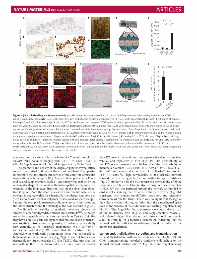
Figure 4 | Vascularized hepatic tissue assembly. a–c, Histology cross-section of hepatic tissue with 10 µm micro-holes on day 6 stained for CD31 toidentify endothelial cells (a,b; n=3, scale bars, 200 µm) and albumin to identify hepatocytes (c; n=3, scale bar, 200 µm). d, Bright-field image of hepatictissue perfused with blue colour dye. Scale bar, 500 µm. e, Fluorescent image of CFDA (green)- and propidium iodide (PI, red)-stained hepatic tissue showshigh cell viability. Scale bar, 200 µm. f, Schematic of terfenadine di�using through the vessel wall with 10 µm micro-holes into the hepatic tissue and thensubsequently being converted into fexofenadine and released back into the vasculature. g, Concentration of fexofenadine in the bioreactor inlet, main andoutlet wells after 24 h perfusion of terfenadine at 10 µM from inlet wells (average± s.e.m., n=4) on day 3. h–k, Immunostaining of E-cadherin and albuminon a human hepatocyte monolayer collagen sandwich (h,i) and human AngioChip hepatic tissue (j,k) on day 7 (n=3). Scale bars, 100 µm. l,m, Histologycross-sections of human AngioChip hepatic tissues with 10 µm micro-holes on day 7 stained with haematoxylin and eosin (l), and for CD31 (m) to identifyendothelial cells (n=3). Scale bars, 200 µm. n, Schematic of urea secretion from the hepatic tissue and release into the vasculature with 10 µmmicro-holes. o, Quantification of urea secretion, normalized to cell number, into the bioreactor main well and outlet well from AngioChip hepatic tissue andcollagen sandwich control on day 3 (average± s.d., n=4).
concentration, we were able to achieve the Young’s modulus ofPOMaC bulk polymer ranging from 53± 8 to 1,423± 651 kPa(Fig. 2d, Supplementary Fig. 8c and Supplementary Tables 1–4).
The geometry and density of the AngioChip parenchymal latticewere further varied to fine-tune the scaffold mechanical propertiesto resemble the anisotropic properties of the adult rat ventricularmyocardium as in design B (Fig. 2a–c,e and Supplementary Figs 9and 10 and Supplementary Table 5). Anisotropy was enabled by therectangular shape of the mesh, with higher spatial density for strutsoriented in the long-edge direction than in the short-edge direc-tion (Fig. 2e). Both the effective elasticity and the ultimate tensilestrength increased with lattice density. Further design iterations canyield scaffolds withmechanical properties tailored for specific appli-cations (for example, humanmyocardiumor human liver) by tuningthe lattice structure and the elasticity of the base material (Fig. 2d).
The limited permeability of synthetic polymers hinders thesuccess of other biodegradable microfluidic scaffolds24,25. Althoughsome biocompatible polymers are permeable to O2/CO2 (ref. 40),they have a limited permeability for small molecules and proteins41,necessitating introduction of porosity to enhance permeability(for example, as in Transwell membranes, 9.3 × 10⁻⁵ cm s−1for 4 kDa molecules42). We found that the cell-free internalAngioChip network with 10 µm micro-holes was permeable toboth small and large molecules (Fig. 2f,g). It was >4 times morepermeable for large molecules (70 kDa TRITC–dextran) than theone without the 10 µm micro-holes, >2 times more permeable
than EC-covered network and more permeable than mammalianvenules and capillaries in vivo (Fig. 2f). The permeability ofthe EC-covered network was higher than the permeability ofmammalian venules ((0.15±0.05)×10−6 cm s−1) for 70 kDa FITC–dextran43 and comparable to that of capillaries44 to proteins(4.3×10⁻⁶ cm s−1). High permeability of the cell-free networkallowed the EC coating to be the dominating transport resistance(Fig. 2f), similar to how the ECs govern the permeability of bloodvessels in vivo. The live cell tracker dye, carboxyfluorescein diacetate(CFDA, 557Da), was perfused through the network surrounded bycardiac cells, staining the live cells in the parenchyma (Fig. 2h),consistent with convection–diffusion transport and metabolicconversion within the tissue. There was no significant leakage ofthe culture medium during perfusion into the parenchymal spaceeven in the absence of the endothelial cell coating (SupplementaryFig. 8d). The AngioChip burst pressure was comparable to thatof the rat femoral vein (Fig. 2i and Supplementary Movie 2)and ∼7-fold higher than the normal systolic blood pressure ina rat (130mmHg) or a human (120mmHg), indicating that thenetwork will be sufficient to withstand blood perfusion in theperipheral circulation.
Lumen endothelialization, sprouting and transmigrationOn endothelialization with human umbilical vein ECs (HUVECs),CD31 immunostaining revealed a confluent endothelium on theluminal network surface (day 2, Fig. 3a–d and Supplementary
NATUREMATERIALS | VOL 15 | JUNE 2016 | www.nature.com/naturematerials
© 2016 Macmillan Publishers Limited. All rights reserved
673

ARTICLES NATUREMATERIALS DOI: 10.1038/NMAT4570
Spontaneous activity
Epinephrine (+)
0 Time (s) 30
Hum
an c
ardi
ac ti
ssue
Thic
k ca
rdia
c tis
sue
Rat t
issu
e
g h i j k
l
m
o p
q
r
s t u
v w
x y z
a c e
b
α-actinin/F-actin
d f
1012141618202224
Are
a (m
m2 )
hESC-CMs+10%hMSCshESC-CMs onlyNeonatal rat-CMs 0
123456
Exci
tatio
n th
resh
old
(V c
m−1
)
0123456
Max
imum
cap
ture
rate
(pps
)
Epinephrine
EndotheliumCardiomyocyte
α-actinin/F-actin
PerfusedCFDA/PI
CFDA/PI Non-perfused 0.00.51.01.5
2.02.53.03.5
∗
1 2 3 4 5 6Day
LDH
(mU
ml−1
) Non-perfusedPerfused
Inlet
Outlet
DAPI/α-actinin/F-actin
DAPI/α-actinin/F-actin DAPI/α-actinin/F-actin DAPI/α-actinin/F-actin
n
0 1 2Day
3 4 5 Rat-CMs hESC-CMs Rat-CMs hESC-CMs
0 125.0 ms
Figure 5 | Vascularized cardiac tissue assembly. a–f, Immunostaining of sarcomeric-α-actinin (green) and F-actin (red) on human AngioChip cardiactissues with 10% human mesenchymal stem cells (hMSCs) on day 1 (a,b) and day 7 (e,f) or without hMSCs on day 7 (c,d) (n=3). Images directly aboveb,d,f, correspond to panels a,c,e, respectively. Scale bars, 500 µm (a,c,e), and 50 µm (b,d,f). In a,c,e, final images were stitched from multiple images.g,h, Immunostaining of sarcomeric-α-actinin (green) and F-actin (red) on Biowire platform (g) and monolayer (h) (n=3) on day 7. Scale bars, 50 µm.i, Quantification of decreasing tissue size due to cell remodelling for neonatal rat cardiomyocytes (rat-CMs), human embryonic stem cell-derivedcardiomyocytes (hESC-CMs), and hESC-CMs mixed with 10% hMSCs (average± s.d., n=3). j,k, Electrical excitability parameters (average± s.d., n=3)on day 7. l,m, Histology cross-sections of human cardiac tissues on day 7 stained with Masson’s trichrome (l), and for CD31 (m) to identify endothelial cells(n=3). Scale bars, 200 µm. n, Activation map of human AngioChip cardiac tissue on day 7 (n=7). Scale bar, 1 mm. Activation of the construct is seen fromthe stimulus point on the right propagating to the left over a time span of 100 ms, in a uniform manner. o, Schematic of perfusion delivery of the epinephrinedrug through the built-in vasculature with 10 µm micro-holes. p, Initial spontaneous contraction trace and drug-stimulated contraction trace of a humancardiac tissue on day 7 perfused with 10 µM epinephrine (n=3). q, Image of multiple thick AngioChip sca�olds patterned in parallel on glass slides. r, Imageof two thick AngioChip cardiac tissues placed face up and side up beside a slice of an adult rat heart. Scale shown in millimetres. s–u, Immunostaining ofF-actin (green) of the cross-section of an endothelialized thick multi-layer human AngioChip cardiac tissue with 20 µm micro-holes on day 3 based onfibrin gel and hESC-derived CMs (n=3). In s, the final image was stitched from multiple images. Panels t,u show high-magnification images of tissue fibresin the parenchymal space near the edge region (t) and the centre region (u). Scale bars, 1 mm (s), and 50 µm (t,u). v,w, Immunostaining of CD31 of anendothelialized microchannel lumen with 20 µm micro-holes that guide sprouting (red arrows; v) and an adjacent parenchymal space with self-assembledmicrovasculature (red arrows; w) in a thick multi-layer human AngioChip cardiac tissue on day 3 (n=3). Scale bars, 50 µm (v,w). x, Immunostaining ofsarcomeric-α-actinin (green) and F-actin (red) on a rat AngioChip cardiac tissue on day 7. Scale bar, 10 µm. y, CFDA (green)- and PI (red)-stained imagesof the cross-section of rat cardiac tissues with 10 µm micro-holes cultivated with or without medium perfusion on day 7 (n=3). Sca�old also stains red.Scale bars, 200 µm. Final images were stitched from multiple images. z, Quantification of lactate dehydrogenase (LDH) secretion from rat cardiac tissuescultivated with or without medium perfusion (average± s.d., n=4). ∗, significant di�erence between groups with p<0.05.
674
© 2016 Macmillan Publishers Limited. All rights reserved
NATUREMATERIALS | VOL 15 | JUNE 2016 | www.nature.com/naturematerials

NATUREMATERIALS DOI: 10.1038/NMAT4570 ARTICLESFig. 11a–c, day 7 Supplementary Fig. 11e–h) with VE-cadherinexpressed at the cell–cell junctions (day 2, SupplementaryFig. 11d). The ECs physically covered the micro-holes on thevessel wall (Fig. 3b,c and Supplementary Fig. 11a–c), conformallyand confluently coating the lumen even at the branch points(Supplementary Movie 3). In response to an angiogenic stimulus,thymosin β4, ECs migrated through the 20 µm micro-holes intothe parenchymal space, a first step of angiogenesis (Fig. 3e–g).Endothelial network permeability dynamically increased inresponse to this biological stimulus (Fig. 3h), a feature unique toliving cells that cannot be reproduced using the polymer materialalone. Human whole blood was perfused through the AngioChipnetwork with or without EC coating at 15 dyne cm−2 (∼5 µl min−1;Re, 0.023; Fig. 3i). The AngioChip network was designed so that theECs in the first- and second-order branches experienced the sameshear stress. Without an EC coating, more platelets bound to thenetwork surface (Fig. 3i–l and Supplementary Fig. 12) and becameactivated, as indicated by their extended pseudopodal morphology(Fig. 3j). Attached platelets exhibited a trend to spread accordingto the blood flow pattern and accumulated more at the stagnationregions of branches and turns (Fig. 3j and Supplementary Fig. 12).Perfused human monocytes, THP-1, exhibited accumulationand adhesion in the network in response to an inflammatory
stimulus, TNF-α (Fig. 3m–p), subsequent migration along theendothelialized surface (Fig. 3q) and transmigration through the10 µm micro-holes on the vessel walls, into the parenchymal space(Fig. 3r). The AngioChip was versatile enough to also enablemigration of Raw264.7 macrophages (Supplementary Fig. 13).
Urea secretion and drug metabolism in vascularized liverPrimary rat hepatocytes mixed with 10% primary rat fibroblasts(to facilitate ECM remodelling and gel compaction9) were seededinto the parenchymal space of an endothelialized AngioChipscaffold, resulting in the aggregation of viable cells (Fig. 4a–e andSupplementary Fig. 14a). Hepatocytes (albumin stained) distributedthroughout the lattice and around the vessel network, and ECs(CD31 stained) coated the inner lumen of the network (Fig. 4a–c).Hepatic tissues were challenged with terfenadine, an antihistaminewithdrawn from the market owing to cardio-toxicity45 (Fig. 4f,g).Terfenadine is generallymetabolized in the liver, to non-cardio-toxicfexofenadine, by the enzyme cytochrome P450 CYP3A4 isoform45.Liquid chromatography–mass spectrometry revealed the presenceof fexofenadine in the outlet well (Fig. 4g).
Entirely human liver AngioChips were engineered usinghuman embryonic stem cell (hESC)-derived hepatocytes46, humanmesenchymal stem cells (hMSCs) as a supporting population and
Endothelialized AngioChip tissue with surgical anastomosis
Implant Microchannel
Red blood cells
With surgical anastomosisNo anastomosis
Artery toartery
Artery tovein
Artery
Vein
a b
c d
e f
m n
g h
i j
o p
k
l 3025
n = 4
P = 0.011
n = 3
No anastomosis
With
anastomosis
20151050
SMA
sta
ined
area
(%)
Before perfusion After perfusion Before perfusion After perfusion
Figure 6 | Surgical anastomosis of the cardiac tissue. a,b, Surgical anastomosis of the AngioChip cardiac tissue on the rat femoral vessels in theconfiguration of artery-to-artery graft (a) and artery-to-vein graft (b). Blood perfusion was established immediately after anastomosis. Papers were placedunder the implants during imaging for better visual contrast. c–j, Cross-section of the non-endothelialized rat cardiac tissue implants 1 week after surgerywithout (c–f; n=3) or with direct anastomosis (g–j; n=4) in the configuration of artery-to-vein graft. The sections were stained withMasson’s trichrome (c,d,g,h), for smooth muscle actin (e,i), and for troponin T (f,j; red). Scale bars, 200 µm (c,g), 100 µm (d,e,h,i) and 50 µm (f,j). k, Imageof a cardiac tissue implant on rat hindlimb 1 week after surgery with direct anastomosis in the configuration of artery-to-vein graft. White dotted lineoutlines the AngioChip implant. l, Quantification of the area stained for smooth muscle actin (average± s.d.). m–p, Histology cross-sections of anAngioChip cardiac tissue endothelialized with Lewis rat primary vein endothelial cells and implanted with direct surgical anastomosis after 1 week (n=3).The sections were stained with Masson’s trichrome (m,n), and for CD31 (o,p). Scale bars, 200 µm (m), 100 µm (n,o) and 50 µm (p). Red dashed boxes inc,g,m,o indicate the imaging location of panels d,h,n,p, respectively.
NATUREMATERIALS | VOL 15 | JUNE 2016 | www.nature.com/naturematerials
© 2016 Macmillan Publishers Limited. All rights reserved
675

ARTICLES NATUREMATERIALS DOI: 10.1038/NMAT4570
HUVECs for inner lumen coating. High-density culture resulted inthe formation of junctions between hepatocytes (Fig. 4j), positivestaining for albumin (Fig. 4k) and bile canaliculi (SupplementaryFig. 15), which were similar in appearance to those obtainedfrom a collagen sandwich (Fig. 4h,i), a commonly used control.Cell density was 0.6 ± 0.2 × 10⁸ cells cm−3 at day 7 with cellspresent throughout the AngioChip volume and CD31+ ECscoating the inner lumen (Fig. 4l,m). Secretion of urea per cell fromendothelialized AngioChip tissues was quantified and shown to behigher than that of the collagen sandwich control (Fig. 4n,o).
Scalable assembly of vascularized cardiac tissueCardiac tissues were created from either hESC-derived (Fig. 5a–wand Supplementary Figs 14b and 18) or neonatal rat cardiomyocytes(Fig. 5x–z). To provide evidence of tissue-level organization,entire AngioChips based on entirely human cells (hESC-derived cardiomyocytes, 10% hMSCs and HUVECs) wereimaged using confocal microscopy. Elongated cell bundleswere present throughout the entire volume (Fig. 5a–f andSupplementary Fig. 14b) including the scaffold interior (Fig. 5l,mand Supplementary Fig. 16). Although gel compaction was possiblewithout the addition of supporting cells, tissues were morecompacted and aligned when 10% MSCs was used (Fig. 5c,e).Cardiac cell density, estimated from the histology sections, was2.3 ± 0.8 × 10⁸ cells cm−3. A condensed tissue formed within5 days (Fig. 5i and Supplementary Figs 14b and 16); a time frameconsistent with previously published studies of non-vascularizedcardiac tissues that relied on gel compaction (5 days for human5
and 7 days for rat47). Synchronous macroscopic contractionswere observed as early as day 4 and the electrical excitabilityparameters of both rat and human tissues fell within the standardrange for non-vascularized rat constructs48 and both rat9,47 andhuman micro-tissues5 (Fig. 5j,k). AngioChip cardiac tissuescontracted macroscopically and compressed the scaffold at eachbeat (Supplementary Fig. 17b) without collapsing the internal vesselnetwork while being perfused (Supplementary Movies 4 and 5).The contractile protein sarcomeric α-actinin and the structuralprotein F-actin were visible in the elongated cells (Fig. 5d,f andSupplementary Fig. 16). Striated cardiac tissue bundles of theAngioChip were similar to those present in the 3D Biowireconstruct, a control that previously improved cardiomyocytestructural maturation5 (Fig. 5g). Cardiomyocytes cultivated inmonolayers, a standard control, exhibited cross-striations, but alack of overall orientation and a less anisotropic overall structure(Fig. 5h) compared with those cultured in AngioChips (Fig. 5f). Atday 7, ECs coated the vessel lumen, and cardiomyocytes distributedthroughout the lattice and packed around the vessels (Fig. 5l,m).Human cardiac tissue exhibited impulse propagation across theentire tissue (4.8± 1.3 cm s−1, n= 7), without conduction block(Fig. 5n and Supplementary Movie 6). These values are lowerthan conduction velocities (voltage) we reported for Biowirespreviously5, as AngioChips were cultivated for a shorter periodof time and without electrical stimulation. Conduction velocitycan be further improved by electromechanical stimulation5,49.Within 30–40min of application, the tissues showed the expectedpositive chronotropic response to epinephrine (10 µM, Fig. 5o,pand Supplementary Fig. 17a).
Engineering millimetre-scale thick tissues was possible usingtwo scalable approaches: by fabricating multi-layer scaffolds(1.58mm thick, Fig. 5q and Supplementary Fig. 20a) usingthe 3D stamping technique with one inlet and one outlet(Fig. 5q–w and Supplementary Fig. 20); or by stacking individualsingle-layer AngioChip tissues followed by cultivation underperfusion to create a single multi-layer thick tissue with multipleinlets and outlets (Supplementary Fig. 19). Fibrin gel or Matrigelhydrogel was independently used, demonstrating versatility of
hydrogel choices for parenchymal cell seeding. The resulting cardiactissue was 1.75–2mm thick with a high density of elongatedcells throughout the cross-section (Fig. 5s–u and SupplementaryFig. 20g,h) and visible cross-striations in the cells from the scaffoldinterior even after only 3 days in culture (Supplementary Fig. 20i).Although the tissue was based on human cardiomyocytes, it wascomparable to the thickness of a physiological structure, the adultrat heart left ventricle (Fig. 5r).
The inner lumen of the AngioChip scaffold in the thick tissueswas fully endothelialized, with organization of endothelial tubule-like structures in the parenchymal space to provide an additionallevel of vascularization (Fig. 5v,w and Supplementary Fig. 20f,j–l). Insome instances, these tubular structures clearly connected with theendothelial cells sprouting, through the 20 µmmicro-holes, from theinner luminal structures of theAngioChip scaffolds (SupplementaryFig. 20f,j–l), demonstrating the direct interaction of the cells in thetwo compartments.
Rat cardiac tissue (Fig. 5x) exhibited higher viability underperfusion compared with the non-perfused controls, whichdeveloped a necrotic core at day 7 (Fig. 5y). Most cell death (thatis, lactate dehydrogenase release) occurred within the first 3 daysand medium perfusion helped mitigate cell death (Fig. 5z) onday 3, clearly demonstrating the benefit of perfusion even for thesingle-layer AngioChip tissues.
Surgical anastomosis of AngioChips to host vasculatureAngioChip scaffolds were connected to the femoral vessels onthe hindlimbs of adult Lewis rats, in artery-to-artery (Fig. 6a)and artery-to-vein (Fig. 6b) mode, to demonstrate two differentconfigurations of direct surgical anastomosis. The inlet and outlet(inner dimensions of 100 µm × 200 µm and outer dimensions of300 µm × 400 µm) were connected to femoral vessels (Fig. 6) withsurgical cuffs. Similar citric acid-based polymers28 have been shownto be antithrombotic in vascular grafts and to support EC growthin vivo30,31. The animals were heparinized only during surgery. Inboth configurations, blood perfusion was established immediately,even in the absence of ECs (Fig. 6a,b), although artery-to-arterymodewasmore technically challenging owing to the higher pressure(Supplementary Movie 7). Blood pulsation was also observed(Supplementary Movie 7), more noticeably in the artery-to-arteryconfiguration. Erythrocytes were observed only in the networksof tissues implanted with direct anastomosis (Fig. 6c,d,g,h,k andSupplementary Figs 21 and 22). One week after the implantationof the AngioChip cardiac tissues, native angiogenesis also tookplace around the implants (Supplementary Fig. 23). The presenceof smooth muscle actin (SMA)-positive cells was merely 2% inthe isolated neonatal rat heart cells4; the significant SMA staining(Fig. 6e,i and Supplementary Fig. 24) suggested the penetration ofmural cells or myofibroblasts into the implanted tissues consistentwith the healing response50 (Fig. 6l). Troponin T immunostainingdemonstrated some elongated cardiomyocytes intertwining withinthe lattice of the AngioChips (Fig. 6f,j and Supplementary Fig. 25).AngioChip cardiac tissues endothelialized with Lewis rat primaryvein ECs were also implanted with direct anastomosis in the artery-to-vein configuration. One week later, ECs coating the lumen wereobserved in 50% of the microchannels from three different implants(2/5, 4/5, 1/5 of visible lumen for implant 1, 2, 3, respectively;Fig. 6m–p). Histologically, 85% of AngioChip lumen were bloodclot free after 1 week in vivo (Supplementary Figs 21 and 22).Specifically, in non-EC-coated AngioChips 3/3, 3/3, 4/5 and 3/5of visible lumens were blood clot free in the four implants and inthe EC-coated groups 3/5, 5/5 and 5/5 were blood clot free in thethree implants. The channelwalls did not degrade appreciably in oneweek, indicating that a longer time is required, as biodegradationand biocompatibility studies showed POMaC polymer discspersisted for at least 5 weeks in vivo (Supplementary Fig. 26).
676
© 2016 Macmillan Publishers Limited. All rights reserved
NATUREMATERIALS | VOL 15 | JUNE 2016 | www.nature.com/naturematerials

NATUREMATERIALS DOI: 10.1038/NMAT4570 ARTICLESOutlookAngioChip provides a powerful platform technology for cultivationof vascularized tissues that overcomes key limitations in the fields oftissue engineering (scalable production of millimetre-sized tissues),organ-on-a-chip engineering (precise placement of endothelial andparenchymal cells, in a simple to operate format) and in vivo tissueimplantation (direct anastomosis). This technology does away withthe requirement that cells be in direct contact with drug-absorbentPDMS in closed-channel systems for organs-on-chips, and doesnot solely rely on hydrogels as cell carriers, as these are typicallytoo fragile to surgically connect into the hosts’ circulation forin vivo implantation. Instead, AngioChip effectively decouples thematerial choice for the engineered vessel network from the materialchoice for the parenchymal space, allowing us to control the initialarchitecture of the vasculature and establish immediate perfusionin vitro and in vivo while sustaining the extensive remodelling ofparenchyma. This micro-engineering approach provided no delayfor tissue endothelialization, as a perfusable endothelial networkwasachieved within one day, before parenchymal cell seeding. The new3D stamping technique allowed us to handle polymer sheets as thinas 25 µm with 10–20 µm holes to create a vessel wall that is merely2–3 cells thick. Thus, paracrine signalling between the ECs and theparenchyma, which usually decays significantly within a very shortdistance (∼10 cells)51, can be sustained.
The thin channel walls in combination with the nanoporesand micro-holes were the key features that allowed effectivemolecular exchange, cell extravasation in a vascularized 3D tissuemodel, and physiologically relevant modes for delivery of testdrugs by convection–diffusion. The addition of 10 µm micro-holescovering only 0.5% of the total network surface area increased thepermeability of the network bymore than four times compared withthemicro-hole-free scaffolds. The resulting permeability was higherthan that of the native vasculature for EC-free AngioChips, ensuringthat the polymer wall did not inhibit transport and enablingsubsequent EC coating to act as a governing resistance. AngioChipnetworks with 20 µmmicro-holes in the top and sidewalls increasedthe coverage of micro-holes to 3.2% of the surface area and guidedthe endothelial sprouts into the parenchyma. To further fine-tunethe vessel permeability tomatch the unique environment in differentorgans, organ-specific ECs should be used. AngioChip also enablesfine-tuning of the elasticity for specific organs, a factor importantfor preventing long-term inflammation and fibrosis52, using arectangular (for anisotropic53) or square (for isotropic54) lattice inthe parenchymal space, difficult to achieve with hydrogels21.
The AngioChip platform enables facile integration of differenttissues on a single device by linking multiple AngioChips inseries (Supplementary Fig. 27). Conventional microfluidic systemsrequire bulky external set-ups thatmake integration difficult. Closedchip configuration is incompatible with the current practices inbiological laboratories and the pharmaceutical industry, which relyheavily on open access for liquid dispensing with micropipetting.Our platform, resembling a standard multi-well plate, maintainsan open configuration so that both the parenchymal space andthe internal vasculature can be accessed with pipetting and allowsdifferent media to be used in each compartment, thus facilitatingco-culture.
Long-term patency of the AngioChip networks should bedetermined in future in vivo studies. Immobilization of heparinonto the inner luminal surface with existing methods50,55,56 couldalso enhance long-term blood vessel patency. Appropriate scaffolddegradation rate is critical50; therefore, long-term degradation ofthe AngioChip in vivo should be examined in the future and fine-tuned for a specific application by adjusting the citric acid contenton the polymer chain27 to enable native mural cells and ECM togradually take over the role of the synthetic polymer vessel wall.Future studies should determine whether the original blood vessels
will remain, on complete AngioChip biodegradation, and whetherthe endothelialized vasculature will exhibit appropriate vasodilationand vasoconstriction properties in vivo. Other non-thrombogenic,photo-crosslinkable scaffoldmaterials, with tissue-specific elasticity,could be explored. Electrical stimulation during cardiac cultureon AngioChips should be used to further synchronize tissuecontractions and mature cells5. The proof of concept for the useof AngioChip in organ-on-a-chip engineering provided here opensthe door for future studies aimed at answering complex biologicalquestions in vitro and in vivo.
In summary, the AngioChip was used to generate both in vitrocardiac and hepatic tissue models with defined vasculature andin vivo implants with direct surgical anastomosis. Uniquely, thisplatform could enable direct and rapid translation of in vitrotesting results to in vivo validation and the development of effectiveregenerative strategies.
MethodsMethods and any associated references are available in the onlineversion of the paper.
Received 8 July 2014; accepted 19 January 2016;published online 7 March 2016
References1. Huh, D. et al . Reconstituting organ-level lung functions on a chip. Science 328,
1662–1668 (2010).2. Kim, H. J., Huh, D., Hamilton, G. & Ingber, D. E. Human gut-on-a-chip
inhabited by microbial flora that experiences intestinal peristalsis-like motionsand flow. Lab Chip 12, 2165–2174 (2012).
3. Kolesky, D. B. et al . 3D bioprinting of vascularized, heterogeneous cell-ladentissue constructs. Adv. Mater. 26, 3124–3130 (2014).
4. Zimmermann, W.-H. et al . Engineered heart tissue grafts improve systolic anddiastolic function in infarcted rat hearts. Nature Med. 12, 452–458 (2006).
5. Nunes, S. S. et al . Biowire: a platform for maturation of human pluripotentstem cell-derived cardiomyocytes. Nature Methods 10, 781–787 (2013).
6. Yang, X., Pabon, L. & Murry, C. E. Engineering adolescence maturation ofhuman pluripotent stem cell-derived cardiomyocytes. Circ. Res. 114,511–523 (2014).
7. Bian, W., Badie, N., Himel IV, H. D. & Bursac, N. Robust T-tubulation andmaturation of cardiomyocytes using tissue-engineered epicardial mimetics.Biomaterials 35, 3819–3828 (2014).
8. Takebe, T. et al . Vascularized and functional human liver from an iPSC-derivedorgan bud transplant. Nature 499, 481–484 (2013).
9. Thavandiran, N. et al . Design and formulation of functional pluripotent stemcell-derived cardiac microtissues. Proc. Natl Acad. Sci. USA 110,E4698–E4707 (2013).
10. Legant, W. R. et al . Microfabricated tissue gauges to measure and manipulateforces from 3D microtissues. Proc. Natl Acad. Sci. USA 106,10097–10102 (2009).
11. Bian, W. Engineered skeletal muscle tissue networks with controllablearchitecture. Biomaterials 30, 1401–1412 (2009).
12. Kim, S., Lee, H., Chung, M. & Jeon, N. L. Engineering of functional, perfusable3D microvascular networks on a chip. Lab Chip 13, 1489–1500 (2013).
13. Zheng, Y. et al . In vitromicrovessels for the study of angiogenesis andthrombosis. Proc. Natl Acad. Sci. USA 109, 9342–9347 (2012).
14. Zhang, B., Peticone, C., Murthy, S. K. & Radisic, M. A standalone perfusionplatform for drug testing and target validation in micro-vessel networks.Biomicrofluidics 7, 044125 (2013).
15. Atala, A., Kasper, F. K. & Mikos, A. G. Engineering complex tissues. Sci. Transl.Med. 4, 160rv112 (2012).
16. Bae, H. et al . Building vascular networks. Sci. Transl. Med. 4, 160ps123 (2012).17. Ye, L., Zimmermann, W.-H., Garry, D. J. & Zhang, J. Patching the heart cardiac
repair from within and outside. Circ. Res. 113, 922–932 (2013).18. Baranski, J. D. et al . Geometric control of vascular networks to enhance
engineered tissue integration and function. Proc. Natl Acad. Sci. USA 110,7586–7591 (2013).
19. Sekine, H. et al . In vitro fabrication of functional three-dimensional tissueswith perfusable blood vessels. Nature Commun. 4, 1399 (2013).
20. Shandalov, Y. et al . An engineered muscle flap for reconstruction of large softtissue defects. Proc. Natl Acad. Sci. USA 111, 6010–6015 (2014).
21. Miller, J. S. et al . Rapid casting of patterned vascular networks for perfusableengineered three-dimensional tissues. Nature Mater. 11, 768–774 (2012).
NATUREMATERIALS | VOL 15 | JUNE 2016 | www.nature.com/naturematerials
© 2016 Macmillan Publishers Limited. All rights reserved
677

ARTICLES NATUREMATERIALS DOI: 10.1038/NMAT4570
22. Vollert, I. et al . In-vitro perfusion of engineered heart tissue throughendothelialized channels. Tissue Eng. 20, 854–863 (2013).
23. Tang, M. D., Golden, A. P. & Tien, J. Fabrication of collagen gels that containpatterned, micrometer-scale cavities. Adv. Mater. 16, 1345–1348 (2004).
24. Ye, X. et al . A biodegradable microvessel scaffold as a framework to enablevascular support of engineered tissues. Biomaterials 34, 10007–10015 (2013).
25. Bettinger, C. J. J. et al . Three-dimensional microfluidic tissue-engineeringscaffolds using a flexible biodegradable polymer. Adv. Mater. 18,165–169 (2006).
26. Bettinger, C. J. et al . Silk fibroin microfluidic devices. Adv. Mater. 19,2847–2850 (2007).
27. Tran, R. T. et al . Synthesis and characterization of a biodegradable elastomerfeaturing a dual crosslinking mechanism. Soft Matter 6, 2449–2461 (2010).
28. Yang, J., Webb, A. R. & Ameer, G. A. Novel citric acid-based biodegradableelastomers for tissue engineering. Adv. Mater. 16, 511–516 (2004).
29. Spiller, K., Freytes, D. & Vunjak-Novakovic, G. Macrophages modulateengineered human tissues for enhanced vascularization and healing. Ann.Biomed. Eng. 43, 616–627 (2014).
30. Kibbe, M. R. et al . Citric acid-based elastomers provide a biocompatibleinterface for vascular grafts. J. Biomed. Mater. Res. A 93A, 314–324 (2010).
31. Motlagh, D. et al . Hemocompatibility evaluation of poly(diol citrate) in vitrofor vascular tissue engineering. J. Biomed. Mater. Res. A 82A,907–916 (2007).
32. Dendukuri, D., Pregibon, D. C., Collins, J., Hatton, T. A. & Doyle, P. S.Continuous-flow lithography for high-throughput microparticle synthesis.Nature Mater. 5, 365–369 (2006).
33. Derby, B. Printing and prototyping of tissues and scaffolds. Science 338,921–926 (2012).
34. Hoshi, R. A. Nanoporous biodegradable elastomers. Adv. Mater. 21,188–192 (2009).
35. Nagueh, S. F. et al . Altered titin expression, myocardial stiffness, and leftventricular function in patients with dilated cardiomyopathy. Circulation 110,155–162 (2004).
36. Weis, S. M. et al . Myocardial mechanics and collagen structure in theosteogenesis imperfecta murine (oim). Circ. Res. 87, 663–669 (2000).
37. Coirault, C. et al . Increased compliance in diaphragm muscle of thecardiomyopathic Syrian hamster. J. Appl. Physiol. 85, 1762–1769 (1998).
38. Omens, J. H. Stress and strain as regulators of myocardial growth. Prog.Biophys. Mol. Biol. 69, 559–572 (1998).
39. Yeh, W. C. et al . Elastic modulus measurements of human liver and correlationwith pathology. Ultrasound Med. Biol. 28, 467–474 (2002).
40. Merkel, T. C., Bondar, V. I., Nagai, K., Freeman, B. D. & Pinnau, I. Gas sorption,diffusion, and permeation in poly(dimethylsiloxane). J. Polym. Sci. B 38,415–434 (2000).
41. Toepke, M. W. & Beebe, D. J. PDMS absorption of small molecules andconsequences in microfluidic applications. Lab Chip 6, 1484–1486 (2006).
42. Gaillard, P. J. et al . Establishment and functional characterization of an in vitromodel of the blood-brain barrier, comprising a co-culture of brain capillaryendothelial cells and astrocytes. Eur. J. Pharm. Sci. 12, 215–222 (2001).
43. Yuan, W., Lv, Y., Zeng, M. & Fu, B. M. Non-invasive measurement of solutepermeability in cerebral microvessels of the rat.Microvasc. Res. 77,166–173 (2009).
44. Adamson, R. H., Huxley, V. H. & Curry, F. E. Single capillary permeability toproteins having similar size but different charge. Am. J. Physiol. 254,H304–H312 (1988).
45. Woosley, R. L., Chen, Y., Freiman, J. P. & Gillis, R. A. Mechanism of thecardiotoxic actions of terfenadine. JAMA 269, 1532–1536 (1993).
46. Ogawa, S. et al . Three-dimensional culture and cAMP signaling promote thematuration of human pluripotent stem cell-derived hepatocytes. Development140, 3285–3296 (2013).
47. Boudou, T. et al . A microfabricated platform to measure and manipulate themechanics of engineered cardiac microtissues. Tissue Eng. A 18,910–919 (2012).
48. Radisic, M. et al . Functional assembly of engineered myocardium by electricalstimulation of cardiac myocytes cultured on scaffolds. Proc. Natl Acad. Sci.USA 101, 18129–18134 (2004).
49. Tulloch, N. L. et al . Growth of engineered human myocardium withmechanical loading and vascular coculture. Circ. Res. 109, 47–59 (2011).
50. Wu, W., Allen, R. A. &Wang, Y. Fast-degrading elastomer enables rapidremodeling of a cell-free synthetic graft into a neoartery. Nature Med. 18,1148–1153 (2012).
51. Bhatia, S., Balis, U., Yarmush, M. & Toner, M. Effect of cell–cell interactions inpreservation of cellular phenotype: cocultivation of hepatocytes andnonparenchymal cells. FASEB J. 13, 1883–1900 (1999).
52. Mazza, E. & Ehret, A. E. Mechanical biocompatibility of highly deformablebiomedical materials. J. Mech. Behav. Biomed. Mater. 48, 100–124 (2015).
53. Engelmayr, G. C. et al . Accordion-like honeycombs for tissue engineering ofcardiac anisotropy. Nature Mater. 7, 1003–1010 (2008).
54. Nava, A., Mazza, E., Furrer, M., Villiger, P. & Reinhart, W. In vivomechanicalcharacterization of human liver.Med. Image Anal. 12, 203–216 (2008).
55. Hoshi, R. A. et al . The blood and vascular cell compatibility ofheparin-modified ePTFE vascular grafts. Biomaterials 34, 30–41 (2013).
56. Sefton, M. V., Gemmell, C. H. & Gorbet, M. B. in Biomaterials Science 3rd edn(eds Ratner, B. D., Hoffman, A. S., Schoen, F. J. & Lemons, J. E.) 758–760(Academic, 2013).
AcknowledgementsWe thank K. Marjan and P. Lai from the University Health Network, Toronto, for theirhelp in the optical mapping analysis. We thank Y. Liu from Osaka University, Japan, forher help in quantifying the platelet coverage on the AngioChip in the blood perfusionstudy. We thank J. W. Miklas and Y. Xiao for their helpful discussion regarding humancardiomyocyte culture and cell seeding. We thank A. Sofla for his help with the POMaCsynthesis. We thank A. Keating and I. Rashedi for providing hMSCs and Y. Zhao for herhelp in culturing and expanding hMSCs. We thank J. Yang for suggestions regardingPOMaC synthesis. This work was made possible by the National Sciences andEngineering Research Council of Canada (NSERC) Steacie Fellowship to M.R. This workwas also financially supported by the Canadian Institutes of Health Research (CIHR)Operating Grants (MOP-126027 and MOP-137107), the Heart and Stroke FoundationGIA T6946, NSERC–CIHR Collaborative Health Research Grant (CHRPJ 385981-10),NSERCDiscovery Grant (RGPIN 326982-10), NSERCDiscovery Accelerator Supplement(RGPAS 396125-10) and National Institutes of Health Grant 2R01 HL076485.
Author contributionsB.Z. developed the AngioChip concept, designed and performed experiments, analyseddata and prepared the manuscript. M.M. contributed to mechanical testing, polymercharacterization, sprouting assay, blood perfusion experiments, and vascular anastomosissurgery. M.D.C. performed the primary rat hepatocyte isolation and urea assay. S.O.differentiated hESC-derived hepatocytes. A.K. performed polymer mechanical testing.A.P. differentiated hESC-derived cardiomyocytes and contributed to the whole bloodperfusion experiment and optical mapping. L.A.W. performed extraction of humanwhole blood. S.M. and K.N. performed optical mapping measurements and analysis.J.K. performed mass spectrometry analysis. L.R. contributed to the direct vascularanastomosis surgery; A.M. performed the direct vascular anastomosis surgery; S.S.N.contributed to the direct vascular anastomosis surgery and writing of the manuscript.A.R.W. contributed to the writing of the manuscript. G.K. contributed to the writing ofthe manuscript. M.V.S. contributed to writing of the manuscript. M.R. developed theAngioChip concept, supervised the work and wrote the manuscript.
Additional informationSupplementary information is available in the online version of the paper. Reprints andpermissions information is available online at www.nature.com/reprints.Correspondence and requests for materials should be addressed to M.R.
Competing financial interestsThe authors declare competing financial interests: details accompany the paper athttp://www.nature.com/naturematerials. M.R. and B.Z. are amongst co-founders ofTARA Biosystems and they hold equity in this company.
678
© 2016 Macmillan Publishers Limited. All rights reserved
NATUREMATERIALS | VOL 15 | JUNE 2016 | www.nature.com/naturematerials

NATUREMATERIALS DOI: 10.1038/NMAT4570 ARTICLESMethodsPOMaC synthesis. To prepare poly(octamethylene maleate (anhydride) citrate)(POMaC) prepolymer, 1,8-octanediol, citric acid and maleic anhydride were mixedat a 5:1:4 molar ratio and melted at 160 ◦C under nitrogen purge. The temperaturewas dropped to 140 ◦C and the mixture was stirred for 2–3 h. The resultantprepolymer solution was then dissolved in 1,6-dioxane and purified throughdrop-wise precipitation in deionized distilled water produced from a Direct-Q 5Water Purification System (Millipore). Precipitated polymer was collected andlyophilized for 2 days. Before photo-crosslinking, POMaC prepolymer was mixedwith 5% (w/w) ultraviolet initiator (Irgacure 2959, Sigma) by melting briefly ataround 90 ◦C. To make nanoporous scaffolds, the POMaC polymer was also mixedwith a porogen, poly(ethylene glycol) dimethyl ether (PEGDM,Mn∼500, Sigma),at 60% (w/w) (Supplementary Fig. 1). Pore-free scaffolds were made withoutadding PEGDM.
AngioChip fabrication. Each layer of the AngioChip scaffold was first generatedin AutoCAD and translated to individual SU-8 masters using standard softlithography techniques as described previously57 (Supplementary Fig. 3 (step 1)).Micro-hole design was directly incorporated in the AutoCAD drawing forAngioChip scaffolds with micro-holes. Experiments performed using AngioChipswith micro-holes were explicitly specified. In AutoCAD, the outer dimensions ofthe AngioChip were set to 5mm length, 3.1mm width and one layer thickness of150–300 µm. Silicone elastomer (poly(dimethylsiloxane), PDMS, 1:15 crosslinkerratio) was moulded against the SU-8 masters and cured at room temperature for2–3 days (Supplementary Fig. 3 (step 2)). Patterned PDMS moulds for the baselayer and upper layers of the 3D scaffold were capped to glass slides and flat PDMSsheets, respectively (Supplementary Fig. 3 (step 3)). The POMaC solution was theninjected into the patterned network through an inlet and outlet and left overnightat room temperature. Injection was achieved either by a syringe pump applying agentle pressure to push the POMaC solution through the mould withoutdelaminating the mould or by a drop of the polymer solution applied on top of theinlet holes with a gentle positive pressure. Overnight, the POMaC solution filledthe entire PDMS moulding including the vertical column extending out from themain mesh network. The gentle positive pressure at the inlet pushed out anytrapped air inside the mould because the PDMS was porous and allowed air toescape (Supplementary Fig. 3 (step 4)). Next, injected POMaC solution wascrosslinked under ultraviolet light at an intensity of 10mJ cm−2 s for 4min, for thepolymer mixed with the porogen, 60%(w/w) PEGDM/POMaC solution, or 10minif no PEGDM was added. Afterwards, the PDMS moulds were uncapped and thepatterned polymer structures were exposed (Supplementary Fig. 3 (step 5)). Thepatterned POMaC sheets for the first layer were attached onto the glass slides andthe patterned POMaC sheets for the following layers were attached onto the PDMSmoulds. The exposed POMaC sheets on the PDMS moulds were then aligned toand pressed against the patterned POMaC sheets on the glass slides with acustomized ultraviolet mask aligner (Q2001, Quintel; Supplementary Fig. 3(step 5)). To bond the layers together, the samples were then exposed to ultravioletat an intensity of 10mJ cm−2 s for 4min or 10min if no PEGDM was added. Afterthe ultraviolet light exposure, the PDMS moulds were released, leaving the twopatterned POMaC sheets bonded together and attached to the glass slides(Supplementary Fig. 3 (step 5)). This process was repeated to bond additionalpatterned POMaC sheets to the established base structure (Supplementary Fig. 3(step 6)). Finally, fabricated scaffolds were immersed in phosphate-buffered saline(PBS) to release them from the glass slides and incubated overnight at roomtemperature to leach out the PEGDM porogen. Multiple scaffolds were patterned inparallel on a single glass slide in a single process (Fig. 1a). Additional tips forAngioChip scaffold fabrication are described in Supplementary Methods.AngioChip scaffold structure, degradation properties, burst pressure, mechanicalproperties and permeability were characterized as described in the SupplementaryMethods. Material biocompatibility in vivo was assessed as described inSupplementary Methods.
Bioreactor design. The bioreactor was composed of four components: a cap, apolycarbonate body, a PDMS base, and a polycarbonate base (Fig. 1c andSupplementary Fig. 6). The bioreactor was designed to accommodate threescaffolds in separate chambers at a time. The polycarbonate body (2.5 cm thick)included 9 wells positioned in three rows: the top row encompassed the inlet wells;the middle row encompassed the main wells, where the AngioChip scaffolds werepositioned; and the bottom row encompassed the outlet wells. The PDMS slab(1mm thick) included three trenches (700 µm deep) where the AngioChipscaffolds were situated. At the bottom of the trenches, micro-posts (200 µm tall)were patterned to lift the AngioChip scaffolds up from the base so that cells/gel canpenetrate underneath the scaffolds and encapsulate the entire scaffolds. The trenchalso included an open inlet and outlet channel where the inlet and outlet of theAngioChip scaffolds could precisely fit. After the AngioChip scaffolds werepositioned, the PDMS base was then sandwiched between the polycarbonate baseand the polycarbonate body so that the open inlet and outlet channels on the
PDMS base were capped with the inlet and outlet of the AngioChip fitted within.The three components were secured with stainless-steel screws.
When assembling the AngioChip scaffold into the bioreactor, it is crucial to notapply excessive pressure onto the scaffold inlet and outlet by screwing thebioreactor too tight. Excessive pressure applied could constrict the inlet and outletchannel and reduce the flow rate. To prevent leakage of fluid around the inlet andoutlet of the scaffold, a drop (around 10 µl) of 1% (w/v) agarose solution sterilizedand heated to 80 ◦C can be applied around the connection of the inlet and outlet toseal any gaps (Fig. 1c (step 1)).
After assembling the scaffold onto the bioreactor, the bioreactor was filled withculture media and incubated at 37 ◦C to prime the scaffold overnight, before cellseeding. As the assembly was done at room temperature, when the bioreactor wasplaced in the incubator at 37 ◦C, the increase in temperature could lead to theexpansion and elimination of any bubbles trapped within the scaffold network.Ethanol should not be used to prime the scaffold at this stage because ethanolsignificantly swells the scaffold and results in failure in the inlet and outletconnection (Fig. 1c (step 1)).
Solution and/or cell suspensions were perfused from the inlet wells through thebuilt-in networks of the AngioChip scaffolds to the outlet wells driven by apressure-head difference between the inlet and outlet wells (Supplementary Fig. 7).The bioreactor was disassembled in sterile conditions to remove the AngioChiptissues for implantation or analysis. When applying parenchymal cells in hydrogelaround the scaffold, 10 µl of the gel/cell suspension was first applied to the scaffold,allowing the cells to fall through the lattice matrix of the scaffold to fill the spaceunder the scaffold as well as the lattice matrix. Then, after 10min of incubation at37 ◦C, an additional 5 µl of the gel/cell suspension was applied on top of the scaffoldto fully encase the scaffold in gel/cell suspension. This sequential seeding methodhelped ensure more even seeding. If all the gel/cell suspension was applied at once,the scaffold would tend to float to the surface of the suspension and result in lesscell/gel on the upper surface of the scaffold (Fig. 1c (step 3)). To examine the fluidflow through the AngioChip scaffold in the bioreactor, AngioChip scaffolds with10 µmmicro-holes and without endothelial cell coating were perfused by adding4ml of PBS in the inlet wells and 1ml of PBS in the main wells. After 24 hincubation at 37 ◦C, the PBS was collected from the inlet, main and outlet wells andweighed to determine fluid distribution in different compartments.
Cell maintenance and differentiation.Human umbilical vein endothelial cells(HUVECs) were purchased from Lonza and cultured with endothelial growthmedium (EGM2, Lonza). Lewis rat vein endothelial cells were purchased fromCellBiologics and cultured with Complete Rat Endothelial Cell Medium(CellBiologics). Human mesenchymal stem cells (hMSCs) were gifts fromA. Keating’s laboratory at University Health Network, Toronto, Canada. hMSCswere isolated from a healthy person under 40 years of age. hMSCs were expandedand cultured in Dulbecco’s modified Eagle medium (Gibco) with 10% (v/v) fetalbovine serum (Gibco), 1% (v/v) HEPES (100 unitsml−1, Gibco) and 1% (v/v)penicillin–streptomycin (100mgml−1, Gibco). Undifferentiated H9 (WA09)human embryonic stem cells (hESCs), purchased from The Wicell ResearchInstitute, were maintained, differentiated into hepatocytes and cultured aspreviously described46,58. To inhibit notch signalling, gamma-secretase inhibitor(GSI) L-685,485 (10 µM, Tocris) was included in the medium throughout theculture period on AngioChip. Primary rat hepatocytes were isolated using amodified two-step isolation procedure from 8-week-old male Sprague Dawleyrats59, according to a protocol approved by the University Toronto Animal CareCommittee. Neonatal rat cardiomyocytes and fibroblasts were isolated by digestingneonatal rat hearts as described previously, according to a protocol approved by theUniversity of Toronto Animal Care Committee57. HES-3 NKX2-5 GFP-positivecells, provided by G. Keller, were maintained, differentiated to humancardiomyocytes, and cultured using previously described techniques60,61. Cells havenot been tested in house for mycoplasma contamination. All cell lines wereindividually stored and logged into the inventory system.
Endothelialization and tissue assembly. To enhance cell attachment onto theAngioChip scaffolds as well as within the internal network, the scaffolds werecoated with 0.2% (w/v) gelatin (from porcine skin, Type A, Sigma) in PBS for 2 hbefore assembly. To prevent cell attachment onto the PDMS base, it was coated with5% (w/v) Pluronic F-127 (Sigma) in PBS for 2 h before assembly. After theAngioChip scaffolds were placed in the bioreactor, endothelial cells were firstseeded into the built-in network of scaffolds by perfusing 10–20 µl of concentratedendothelial cell suspension (25 million cellsml−1) in endothelial cell media into thenetwork for 1min. The flow was then stopped to allow the cells to attach understatic conditions for 2 h. Unattached cells were then flushed by adding 1ml ofendothelial cell media to the inlet wells, thus initiating perfusion throughAngioChip scaffolds under a flow rate less than 0.7 µl min−1 (0.62 dyne cm−2,Re, 0.01) to apply minimal stress to the cells while feeding the cells with sufficientmedia. After 2 h incubation, 3ml of EC medium was then added to increase theflow rate to near a one-day average perfusion rate of 0.7 µl min−1. Within the
NATUREMATERIALS | www.nature.com/naturematerials
© 2016 Macmillan Publishers Limited. All rights reserved

ARTICLES NATUREMATERIALS DOI: 10.1038/NMAT4570
network, the endothelial cells were allowed to proliferate and form a confluentnetwork overnight (the bioreactor can be temporarily tilted at 45◦ angle to increaseperfusion rate and accelerate EC proliferation overnight). Before the seeding ofparenchymal cells, all EC media were removed from the bioreactor. On day 1, tocreate an AngioChip hepatic tissue, primary adult rat hepatocytes or hESC-derivedhepatocytes mixed with 20% hMSCs were seeded at 100–200 million cellsml−1with 15 µl Matrigel (BD Biosciences) onto the AngioChip scaffolds. To create a ratAngioChip cardiac tissue, cardiomyocytes isolated from neonatal rats were seededwith 15 µl (single-layer network) collagen/Matrigel mixture at 100–200 millioncellsml−1 onto each AngioChip scaffold. The composition of the collagen/Matrigelmixture was as follows: 2.5mgml−1 of rat tail collagen type I (BD Biosciences)neutralized by 1N NaOH and 10×M199 medium as described by themanufacturer, supplemented with 4.5 µgml−1 glucose, 1% HEPES, 10% (v/v)Matrigel (BD Biosciences), and 2 µgml−1 NaHCO3. To create a human AngioChipcardiac tissue, hESC-derived cardiomyocytes mixed with or without 10% hMSCswere seeded with 15 µl (single-layer network) Matrigel (BD Biosciences) at100–200 million cellsml−1 onto each AngioChip scaffold. After 30min gelation at37 ◦C, 1ml of hepatocyte medium or cardiomyocyte medium was added to themiddle well. After the seeding of parenchymal cells, an additional 4ml ofendothelial cell medium was also added to the inlet wells, increasing mediumperfusion rate back to a one-day average perfusion rate of 0.7 µl min−1(0.62 dyne cm−2, Re, 0.01). As a control, hepatocyte collagen sandwich culture wasused by first plating hESC-derived hepatocytes with 20% hMSCs on 48-well plates(0.14 million cells per well). Attached cells were then encapsulated with collagen(500 µl per well). As a control for cardiac cell culture, cardiac Biowires were formedby seeding hESC-derived cardiomyocytes with 10% hMSCs around a surgicalsuture according to a previously published protocol5. Cardiac monolayer culturewas formed by seeding hESC-derived cardiomyocytes with 10% hMSCs on 96-wellplates (0.02 million cells per well).
Thick cardiac tissues were assembled by centrifugation-facilitated cell seedingof the thick AngioChip scaffolds with 20 µmmicro-holes. The built-in network ofthe AngioChip scaffold was first endothelialized and cultured for one day. Around30–40 million cells made up of 20% endothelial cells (HUVECs), 20% hMSCs, and80% hESC-derived cardiomyocytes were mixed with 40 µl of fibrinogen(33mgml−1). A total of 40 µl parenchymal cell solution was pipetted onto eachthick scaffold at once followed by centrifugation at 87g for 3min. Alternatively,three batches of 14 µl cell solution were sequentially pipetted followed bycentrifugation after each batch at 28–87g for 1min (the centrifuge should be wellbalanced to ensure a smooth spinning-speed acceleration). Finally, 5 µl of thrombin(25Uml−1) was added to the top of the tissue to induce gelation. Seeding withMatrigel was performed in a similar fashion only with the temperature control setat 4 ◦C. An extended bioreactor column was added to the bioreactor to increase theheight of the bioreactor chambers to generate a higher-pressure head to increaseperfusion for the thick tissue. Fifty millilitres of endothelial cell medium was addedto the inlet chamber and 15ml of cardiomyocyte medium was added to the mainchamber of the AngioChip bioreactor. Both media were supplemented with10 µgml−1 aprotinin.
For the tissue stacking approach, three endothelialized single-layer AngioChipcardiac tissues were seeded with human cells and cultured as described above forthree days. They were then removed from their individual bioreactor wells andthen stacked onto each other in a new bioreactor with a 1.5-mm-deep main tissuewell. The three tissues were held in place during cultivation with U-shapedstainless-steel micro-pins.
Tissue characterization. Endothelial sprouting from AngioChip, whole bloodperfusion, monocyte and macrophage adhesion and migration on the AngioChipvasculature were performed as described in detail in the Supplementary Methods.Histology, immunostaining and quantification of cell density in AngioChip hepaticand cardiac tissues were assessed as described in the Supplementary Methods. Ureaassays on hepatic tissue and liver drug testing were performed as described in theSupplementary Methods. Functional characterization of engineered cardiac tissue,lactate dehydrogenase assays on cardiac tissue and cardiac drug testing wereperformed as described in the Supplementary Methods.
Rat femoral vessel surgery. All procedures below were performed at theDepartment of Comparative Medicine Animal Facility, University of Toronto,under a protocol approved by the Committee on Animal Care. AngioChip scaffoldsalone, those cultured with Lewis neonatal rat cardiomyocytes, or endothelialized
AngioChip scaffold cultured with Lewis neonatal rat cardiomyocytes on day 7 wereused for the implantation experiments. Lewis rat vein endothelial cells(CellBiologics) isolated from inferior vena cava tissue of 6–8-week-old Lewis ratswere used to endothelialize the AngioChip scaffolds for implantation. Todemonstrate the ability of AngioChip to be implanted in two different ways withdirect anastomosis in vivo, we used two different configurations: artery bypassconfiguration and artery-to-vein configuration. To improve the mechanicalstability of the anastomosis site, the inlet and outlet segment of the AngioChipscaffold were made without the use of porogen. During the surgery, adult maleLewis rats (150–250g ) from Charles River were first anaesthetized with 1–3%isoflurane at flow rate of 1 lmin−1. Analgesic was administered (5mg kg−1ketoprofen, SQ) and both hindlimbs were prepared for surgery. For the surgicalprocedure, a dissection microscope was used to obtain an enlarged view of thehindlimb region. Skin was shaved and incisions were made on the left leg,approximately 2 cm long starting from the knee to the medial thigh. Then,subcutaneous fat tissue and the underlying neurovascular bundle were revealed.The femoral artery and vein were dissected and separated from the nerve. For theartery bypass configuration, a segment of the femoral artery (approximately 1.5 cmin length) was fully exposed and ligated for the insertion of the AngioChip cardiactissue. The two ends of the artery were clamped with a microsurgicalapproximating clamp to temporarily stop blood flow during the surgery. One25 gauge cuff (polyimide tube) was inserted into each end of the artery and securedwith 7-0 sutures. Biodegradable surgical cuffs can also be used in futureapplications62. The inlet and outlet of the AngioChip cardiac tissue were theninserted into the cuffs and sealed with tissue glue (Cyanoacrylate). Clamps werethen removed and blood perfusion was established. For the artery-to-veinconfiguration, a segment (approximately 5mm in length) of the femoral artery andfemoral vein was fully exposed and ligated for the insertion of the AngioChipcardiac tissue. The ends of the artery and vein were clamped with a microsurgicalapproximating clamp to temporarily stop blood flow during the surgery. One25 gauge cuff (polyimide tube) was inserted into each top end of the artery andvein and secured with 7-0 sutures. The bottom ends of the artery and vein weresealed with 7-0 sutures. The inlet and outlet of the AngioChip cardiac tissue werethen inserted into the cuffs and sealed with tissue glue (Cyanoacrylate). Clampswere then removed and blood perfusion was re-established. Last, another cardiactissue patch was implanted to the right leg subcutaneously in a similar manner butwithout anastomosis to serve as a control. For post-operative pain management,rats received ketoprofen (5mg kg−1, subcutaneous injection daily) for 2 days. At the1-week time point the animals were humanely euthanized and the tissue implantswere isolated for histology sectioning.
Statistical analysis. Significant differences between experimental groups weredetermined using independent two-tailed Students’ t-test unless specifiedotherwise. In Fig. 2f, one-way analysis of variance (ANOVA) was used with anormality test (Shapiro–Wilk) and pairwise multiple-comparison procedures(Holm–Sidak method). In Fig. 4g, Kruskal–Wallis one-way ANOVA on ranks wasused and followed by pairwise multiple comparison procedures(Student–Newman–Keuls method). In Fig. 5z, two-way repeated measuresANOVA was used with a normality test (Shapiro–Wilk) and followed by pairwisemultiple comparison procedures (Holm–Sidak method). p<0.05 was consideredsignificant for all tests.
References57. Zhang, B., Green, J. V., Murthy, S. K. & Radisic, M. Label-free enrichment of
functional cardiomyocytes using microfluidic deterministic lateral flowdisplacement. PLoS ONE 7, e37619 (2012).
58. Ogawa, M. et al . Directed differentiation of cholangiocytes from humanpluripotent stem cells. Nature Biotech. 33, 853–861 (2015).
59. Berry, M. & Friend, D. High-yield preparation of isolated rat liver parenchymalcells: a biochemical and fine structural study. J. Cell Biol. 43, 506–520 (1969).
60. Kennedy, M., D’Souza, S. L., Lynch-Kattman, M., Schwantz, S. & Keller, G.Development of the hemangioblast defines the onset of hematopoiesis inhuman ES cell differentiation cultures. Blood 109, 2679–2687 (2007).
61. Lian, X. et al . Directed cardiomyocyte differentiation from human pluripotentstem cells by modulating Wnt/β-catenin signaling under fully definedconditions. Nature Protocols 8, 162–175 (2013).
62. Zeebregts, C., Heijmen, R., Van Den Dungen, J. & Van Schilfgaarde, R.Non-methods of vascular anastomosis. Br. J. Surg. 90, 261–271 (2003).
© 2016 Macmillan Publishers Limited. All rights reserved
NATUREMATERIALS | www.nature.com/naturematerials