Embed Size (px)
Citation preview

11/1/2017 1MSKU, Turkey
Bio-Inspired Engineering: Self-Healing
Materials
Sayavur I. Bakhtiyarov
New Mexico Institute of Mining & Technology, USA
11/1/2017 MSCU, Turkey 2
Outline
• Biological aspirations (anatomy of skin)
• Concept and definition
• Mechanism of crack propagation
• Crosslinking phenomenon
• First reports on self-healing materials
• Self-healing polymer composites
• High temperature self-healing metal composite
• Conclusions

11/1/2017 MSCU, Turkey 3
Abbreviations
AES – Auger electron spectroscopy
BSE – back scattered electrons
EB PVD – electron beam physical vapor deposition
FRP - fiber reinforced polymer
HT – high temperature
LM – light microscopy
NCT – nanocarbon tubes
PAA - polyacrylamide
RE – reactive elements (La, Ce, Y, Hf, etc.)
SEM – scanning electron microscopy
SS – stainless steel
TBC – thermal barrier coating
TDCB - tapered double-cantilever beam
TGO – thermo-re-growth oxide
UV - ultraviolet
WDS – wave-length dispersive spectrometry

11/1/2017 MSCU, Turkey 4
Anatomy of Skin
Goldman & Bennett, 2000
The skin is a dynamic organ
containing a variety of tissues,
cell types, and specialized
structures, which together serve
multiple functions important to
health and survival.
The skin interfaces with our dry,
hostile environment and
provides many functions crucial
to survival, including protection
against the elements (e. g.,
ultraviolet irradiation,
mechanical and chemical injury,
invasion by infection agents,
and prevention of desiccation
and dehydration) and
thermoregulation.

11/1/2017 MSCU, Turkey 5
Inflammatory reactions in the skin and wound healing
Healing proceeds temporally in three phases:
1) Substrate
2) Proliferative, and
3) Remodeling
The initial substrate phase encompassing the first 3 to 4 days after
wounding, is so named because the cellular and other interactions lead to
preparation for subsequent events. During this phase, vascular and
inflammatory components prevail.
The proliferative phase (10 to 14 days after wounding) results in
regeneration of epidermis, neoangiogenesis, and proliferation of
fibroblasts with increased collagen (protein) synthesis and closure of the
skin defect.
The final remodeling takes place over 6 to 12 months, during which time a
more stable form of collagen is laid down to form a scar of progressively
increasing tensile strength.

11/1/2017 MSCU, Turkey 6
Biological
attribute
Composite/poly
mer
engineering
Biomimetic self-healing
or repair strategy
Reference
‘Concept of self-
healing’
Remendable
polymers
Bioinspired healing requiring external
intervention to initiate repair
Chen et al 2002,
2003,
Hayes et al 2005
Bleeding Capsules Action of bleeding from a storage medium housed within the
structure. 2-phase polymeric cure process rather than enzyme
‘waterfall’ reaction
White et al 2001,
Kessler and White
2001,
Kessler et al 2002
Bleeding Hollow fibers Action of bleeding from a storage medium housed within the
structure. 2-phase polymeric cure process rather than enzyme
‘waterfall’ reaction
Bleay et al 2001,
Pang and Bond
2005a, 2005b,
Trask and Bond 2006
Blood cells Nano-particles Artificial cells that deposit nano-particles into regions of damage Lee et al 2004,
Verberg et al 2006
Blood flow
vascular network
Hollow fibers 2D or 3D network would permit the healing agent to be
replenished and renewed during the life of the structure
Toohey et al 2006,
Williams et al 2006
Blood clotting Healing resin Synthetic self-healing resin systems designed – to clot locally to
the damage site. Remote from the damage site clotting is inhibited
and the network remains flowing.
-
Skeleton/bone
healing
Reinforcing
fibers
Deposition, resorption, and remodeling – of fractured reinforcing
fibers
-
Elastic/plastic
behavior in
reinforcing fibers
Reinforcing
fibers
Repair strategy, similar to byssal thread, where –repeated breaking
and reforming of sacrificial bonds ca occur for multiple loading
cycles
-
Tree bark healing
compartmentalizati
on
- Formation of internal impervious –boundary walls to protect the
damaged structure from environmental attack
-
Biomimetic self-healing inspiration in advanced composite structures (Trask et al, 2007)

11/1/2017 MSCU, Turkey 7
Mechanism of crack propagation at the interface (by Cook and Gordon)

11/1/2017 MSCU, Turkey 8
Typical pattern of “main” crack propagation in:
a) Layered materials
(composites, wood)b) Homogeneous materials
(metal, glass)

11/1/2017 MSCU, Turkey 9
Bi-modal architecture of wood as a crack arrestor (Gibson & Ashby, 1997)
Utilization of the concepts arising
in wood where sap channels act
as crack arrestors to devise
bimodal architectures which
enhance the toughness of cellular
solids
Possible innovative materials
developments for structural and
multifunctional applications,
allowing in addition the degree of
freedom of multi-materials
designs

11/1/2017 MSCU, Turkey 10
A self healing material is a material that has the built-
in ability to partially repair damage occurring during
its service life time.
Usually, a material's properties degrade over time
due to damage (such as microcracks) on a
microscopic scale. These cracks can grow and
ultimately lead to failure. Self-healing materials
address this slow failure through the inclusion of an
"active" phase that responds the micro-damage by
initiating a repair mechanism.
Definition of “Self-healing material” (from Wikipedia)

11/1/2017 MSCU, Turkey 11
Schematical crosslink reaction between crosslinker
and polymer
Crosslinking
Crosslinked Polymer - a polymer in which adjacent linear molecular chains are
joined at various positions by covalent bonds

11/1/2017 MSCU, Turkey 12
0
5
10
15
20
25
30
35
40
45
0 50 100 150 200
Shear Rate, s-1
Sh
ea
r S
tre
ss
, N
m-2
Crosslinking
Rheological studies on crosslinked PAA composite gel used in oilfield
operations (Bakhtiyarov, 1976).
0
10
20
30
40
50
60
70
80
0 20 40 60 80 100 120
Shear Rate, s-1
No
rma
l S
tre
ss
, N
m-2

11/1/2017 MSCU, Turkey 13
Electric fields inhibit stress cracks in metals
A strong electric field can stabilize the surface of
metals and other electrically conducting and
semiconducting crystalline solids, and inhibit the
formation of fissures caused by mechanical stress (J.
Materials Performance, April 2008).
The tip of the crack is a concentrator not only for the
mechanical stresses and also for the electric current.
The latter causes heating and even melting of the
material around the crack tip.

11/1/2017 MSCU, Turkey 14
Electric fields inhibit stress cracks in metals

11/1/2017 MSCU, Turkey 15
Self healing after radioactive damage (Popular Mechanics, May 2007, in
Russian)
Computer simulations are demonstrated a possibility to develop self-repairing ceramic
materials with the ability to recover after radioactive damage. This discovery can lead
to development more effective components of nuclear power stations and more safe
storages for nuclear wastes.
Zr stabilized with Y (Yttrium) inclusions remains
undamaged after exposure to the strong radioactive
effect. Its structural changes are distributed quite
uniform, and material properties are not changed
significantly.
In regular Zr the defects generate the damaging clusters
(Ram Devanathan & William Weber).

11/1/2017 MSCU, Turkey 16
The first report of a man-made self healing material was by the
group of Dr. Scott White of the University of Illinois at Urbana-
Champaign. They reported an epoxy system containing
microcapsules. These microcapsules were filled with a (liquid)
monomer. If a occurs in this system, the microcapsule will rupture
and the monomer will fill the crack. Subsequently it will
polymerise, initiated by catalyst particles (Grubbs catalyst) that are
also dispersed through the system. This model system of a self
healing particle proved to work well: the service life time of a
structure made of such material will be significantly higher.
Currently a number of research groups world wide is developing
self healing mechanisms for essentially all materials classes
(metals, polymers, ceramics, cemetitious, elastomeric and fibre-
reinforced composite materials).
First Report

11/1/2017 MSCU, Turkey 17
The autonomic healing concept (White et al, 2001, University of Illinois
at Urbana-Champaign)A microencapsulated healing
agent is embedded in a
structural composite matrix
containing a catalyst capable of
polymerizing the healing agent.
(a) Cracks form in the matrix
wherever damage occurs;
(b) the crack ruptures the
microcapsules, releasing the
healing agent into the crack
plane through capillary action;
(c ) the healing agent contacts
the catalyst, triggering
polymerization that bonds the
crack faces closed.

11/1/2017 MSCU, Turkey 18
(a) Stress state in the vicinity of a planar
crack as it approaches a spherical
inclusion embedded in a linearly elastic
matrix and subjected to a remote tensile
loading perpendicular to the fracture
plane. The left and right figures
correspond to an inclusion three times
stiffer (E* = Esphere/Ematrix = 3) and
three times more compliant (E* = 1/3)
than the surrounding matrix,
respectively. The Poisson's ratios of the
sphere and matrix are equal (0.30).
(b) A time sequence of video images
shows the rupture of a microcapsule
and the release of the healing agent. A
red dye was added for visualization.
The elapsed time from the left to right
image is 1/15 s. Scale bar, 0.25 mm.
(c) A scanning electron microscope image
shows the fracture plane of a self-
healing material with a ruptured urea-
formaldehyde microcapsule in a
thermosetting matrix.
Rupture and release of the microencapsulated healing agent

11/1/2017 MSCU, Turkey 19
ESEM image showing ruptured
microcapsule (White et al, 2001)
This scanning electron microscope image shows
microcapsules used in self-healing polymers. The
diameter of the microcapsules in the center of the
image is approximately 100 microns.

11/1/2017 MSCU, Turkey 20
Images of a self-healing test specimen with red dyed microencapsulated
healing agent embedded in the epoxy matrix
(a) Virgin sample.
(b) Cracks form in the matrix wherever damage occurs. A crack ruptures the
microcapsules, releasing the healing agent into the crack plane through capillary
action.
(c) The two halves of the specimen after it has been fractured into two pieces.
(d) On the crack faces, red healing agent is released from ruptured urea-formaldehyde
microcapsules embedded in the epoxy.

11/1/2017 MSCU, Turkey 21
Hollow glass fibers (with ~200 mm spacing,
filled with self-healing agents) embedded in
carbon fiber reinforced composite laminate
Embedded hollow glass fibers (35 mm in
diameter) can be filled with uncured epoxy
polymer or chemical curing agent
Composites with hollow fibers (Dr. Bond, University of Bristol, UK)

11/1/2017 MSCU, Turkey 22
A new self-healing concept
with healing agent and
catalyst encapsulated within
double-walled nanotubes
(NMT USA)
Self-healing concepts with double-walled nanotubes

11/1/2017 MSCU, Turkey 23
(a) Optical micrograph of
microbubbles in
CO2/oil/water emulsion;
(b) SEM micrograph of
hollow microcapsules
made by UV-initiated
polymerization;
(c) SEM micrograph of
crushed microcapsules
made by UV-initiated
polymerization;
(d) SEM micrograph of
solid microspheres made
by thermally initiated
polymerization.
Microencapsulation Zhongshan University (China)

11/1/2017 MSCU, Turkey 24
The technology has being tested initially with a system that contains two concentric
cylinders (the inner one has a thin layer of insulating ceramic coating), with an
electrical field applied to the system.
Between the two cylinders a colloidal dispersion of polystyrene or silica particles
were used to repair defects that occur in the inner cylinder when high stress is
applied.
When a defect occurs in the insulating coating, underneath metal was exposed to
create high current density at the damaged site, causing colloidal particles to
coagulate around the defect
SELF-HEALING via Electrohydrodynamic Coagulation
A schematic for a self-healing
system that uses the
electrohydrodynamic coagulation
of particles to close a defect in a
cylinder wall (Trau et al., 1997)

11/1/2017 MSCU, Turkey 25
Recently, it was found that micellar copper oxide
additions to viscoelastic lubricants significantly improve
their anti-wear and friction reducing properties.
Under certain friction conditions the atomic copper
forms a self-recoverable (“self-healing”) tribofilm on the
cutting (drilling, machining) tool surfaces.
This film decreases the contact area between the
workpiece and the tool, the friction coefficient, the
temperature and tool wear. As a result, the tool life will
be increased.
SELF-HEALING VISCOELASTIC TRIBOLOGICAL
NANOSYSTEMS
11/1/2017 MSCU, Turkey 26
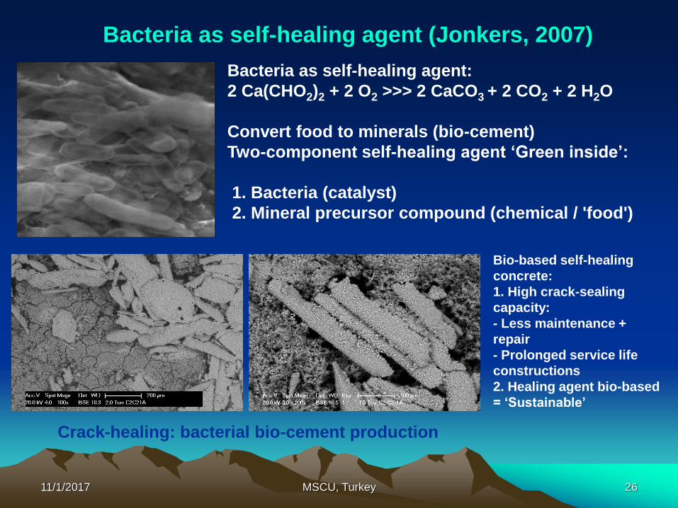
Bacteria as self-healing agent:
2 Ca(CHO2)2 + 2 O2 >>> 2 CaCO3 + 2 CO2 + 2 H2O
Convert food to minerals (bio-cement)
Two-component self-healing agent ‘Green inside’:
1. Bacteria (catalyst)
2. Mineral precursor compound (chemical / 'food')
Bacteria as self-healing agent (Jonkers, 2007)
Crack-healing: bacterial bio-cement production
Bio-based self-healing
concrete:
1. High crack-sealing
capacity:
- Less maintenance +
repair
- Prolonged service life
constructions
2. Healing agent bio-based
= ‘Sustainable’
11/1/2017 MSCU, Turkey 27
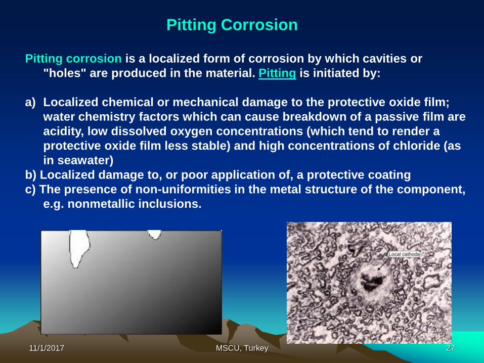
Pitting corrosion is a localized form of corrosion by which cavities or
"holes" are produced in the material. Pitting is initiated by:
a) Localized chemical or mechanical damage to the protective oxide film;
water chemistry factors which can cause breakdown of a passive film are
acidity, low dissolved oxygen concentrations (which tend to render a
protective oxide film less stable) and high concentrations of chloride (as
in seawater)
b) Localized damage to, or poor application of, a protective coating
c) The presence of non-uniformities in the metal structure of the component,
e.g. nonmetallic inclusions.
Pitting Corrosion

11/1/2017 MSCU, Turkey 28
Nanoscale ceramic coating to heal pitting corrosion (Aita, UMW, 2008)
Ceramic nanostructure coating is
proposed to prevent pit growth on
stainless steel (SS) at the sub-microscopic
level.
To mitigate pit corrosion the steel can be
coated with passive overlayer of Al2O3,
SiO2 or Ta2O5 (tantalum pent-oxide).
However, single-layer films can fail
because pinholes act as channels to
quickly transport electrolytes through the
film to the steel surface.
The substrate is coated with a multi-
layered nanolaminate ceramic film that
prevents pit growth at every new layer.

11/1/2017 MSCU, Turkey 29
The metallurgical processes such as sintering and dynamic
precipitation in response to loading conditions may initiate different
levels of self healing in Al alloys. Precipitation of crystalline
materials into cracks occurs on a wide scale in geological
processes, but biological processes governing the repair of bone
and tissue are more relevant because of their inherent efficiency.
The service life of an Al alloy is related to its microstructure and the
changes occur during service:
Δ Service life = f (Service Environment, Δ Microstructure)
If the microstructure responds or adapts unfavorably to its
conditions of loading and accumulates damage, then the service life
will be reduced.
Self Healing in Metal Alloys (Lumley, 2007)

11/1/2017 MSCU, Turkey 30
Development of High-Temperature Corrosion
and Creep Resistant Nb, Mo and Cr Based
Compositions with Protective Self-Healing
Coating of Fe-45%Cr-4%Al-1%Ni-0.3%La Alloy
New Mexico Institute of Mining and Technology &
Georgian Technical University

11/1/2017 MSCU, Turkey 31
The traditional TBC do not exhibit any self-healing in
contrast with the metallic bond coating.
These TBCs are made of a ceramic material and are the
most critical part of the coating system for the lifetime of
a coated component.
During heating and cooling, high stresses develop due
to a mismatch between the coefficients of thermal
expansion of the substrate and the different layers in the
coating system.
The coating system life span is set by the development
of crack patterns that coalesce and ultimately lead to
failure.
TBC

11/1/2017 MSCU, Turkey 32
The selection of TBC ceramic materials is restricted by
some basic requirements (Cao et al, 2004):
1) High melting point
2) No phase transformation between room temperature
and operation temperature
3) Low thermal conductivity
4) Chemical inertness
5) Thermal expansion matching with the metallic
substrate
6) Good adherence to the metallic substrate
7) Low sintering rate of the porous microstructure
TBC requirements

11/1/2017MSCU, Turkey
33
Coating
Substrate
Self-organizing
TBC{
Scar (Cr2O3, Fe, Al, Y, La
complex oxide)
TGO (Al2O3) sub-layer
HT corrosion resistant alloy
(Fe-Cr-Al-RE) (RE = La, Y)
HT creep resistant metal
(Nb, Mo, Ta, Cr)
Heterogeneous architectured metal / metal / ceramic high
temperature coating systems

11/1/2017 MSCU, Turkey 34
Self-organizing, protective oxide scales on the Fe-
44%Cr-1%Ni-4%Al-0.3%La alloy surface
(Kutelia & Bakhtiyarov, 2008)
Amorphous Beilby layer formation due to the self-
organizing dissipative processes on the surface of an Fe-
Cr-Ni-Al-La alloy with high (>40%) chromium content
The Al2O3 layer is characterized by high adherence with
metallic substrate and provides protective features
against both high temperature (1200oC) oxidation of the
matrix and resistance to abrasion.
A thin (several microns) scale is formed by the
pretreatment alloy’s surface at 1200oC.

11/1/2017 MSCU, Turkey 35
a) 50Å (the structure is
amorphous);
b) 300Å (in Roentgen-amorphous
condition);
c) 1300Å (polycrystalline,
desegregated structure)
Electron-diffraction patterns (the electronograms) obtained by
reflection from the polished surface from different depths
A schematic of structure changes by
thickness on mechanical polished
Fe-44%Cr- 4%Al-0.3%La alloy
surface.

11/1/2017 MSCU, Turkey 36
SEM images of the Fe-44%Cr-1%Ni-4%Al-0.3%La specimen surface
oxidized in the air at 1200OC for 5 hours. The samples have previously
been mechanically polished up to the formation of Bailby layer
The surface layer (≤1μm thickness) of the mechanically polished specimen of Fe-
44%Cr-1%Ni-4%Al-0.3%La alloy consists of the amorphous Beilby layer. Its adjacent
matrix layer, crushed due to the plastic deformation, formed an entropy “excited”
functional system, which at 1200oC forms an oxide surface layer with a micro-wrinkles
modulated structure of uniform thickness in the form of mixture of nano-crystallites
(100-500nm) made of oxides of atoms constituting the basic metallic matrix.

11/1/2017 MSCU, Turkey 37
SEM images of the Fe-44%Cr-1%Ni-4%Al-0.3%La alloy after oxidation cycles
1200OC/5 hours+1400OC/ 1 hour, where the relatively loose superficial
structure is removed
Beneath this layer a thin alumina scale was formed. An increasing of the
oxidation temperature (~1400oC) causes the regrowth of nanocrystallites
and also the recrystallization processes accompanied by solid-phase
reactions between oxide nano-particles. This leads to the scale
delamination at the superficial oxide thin uniform alumina layer interface.

11/1/2017 MSCU, Turkey 38
The results of tribological tests: a) & b) dependence of friction coefficient and
wear intensity on friction velocity respectively; curves plotted for the
specimens of investigated alloy before and after oxidation at elevated
temperature.
0
0.02
0.04
0.06
0.08
0.1
0.12
0.14
0.16
0.18
0.2
0 0.2 0.4 0.6 0.8 1 1.2 1.4
v, m/s
f, f
ricti
on
co
eff
icie
nt
unoxidized specimen; test temperature 28-55 C
oxidized specimen; test temperature 600 C
0
10
20
30
40
50
60
70
80
90
0 0.2 0.4 0.6 0.8 1 1.2 1.4
v, m/s
Ix10
-11,
wear
inte
nsit
y
unoxidized specimen; test temperature 28-55 *C
oxidized specimen; test temperature 600 *C
(a) (b)
Pre-oxidization treatments where a thin oxide ceramic layer was formed on
the disk surface can be useful in reducing friction, wear and galling

11/1/2017 MSCU, Turkey 39
SEM micrographs showing the structure of
an EB-PVD Fe-45%Cr-1%Ni-4%Al-
0.3%La overlay coating deposited on
the substrates:
a) single crystal of Nb
b) single crystal of Mo
High-Temperature Self-Healing Coating

11/1/2017 MSCU, Turkey 40
SEM images and WDS spectra of the EB-PVD Fe-45%Cr-1%Ni-4%Al-0.3%La areas deposited at 650OC
of single crystal substrate of Nb (110): a) the solidified drop of evaporated alloy splashed on the
coating surface; b) higher magnification of the area indicated on (a) which demonstrates the
superfine graininess of coating structure; c) WDS spectrum of the solidified drop;
d) WDS spectrum of the marked area on the coating.
High-Temperature Self-Healing Coating

11/1/2017 MSCU, Turkey 41
SEM images and WDS spectra of the EB-PVD Fe-45%Cr-1%Ni-4%Al-0.3%La areas deposited at 650OC
of single crystal substrate of Mo (110): a) the solidified drop of evaporated alloy splashed on the
coating surface; b) higher magnification of the area indicated on (a) which demonstrates the superfine
graininess of coating structure; c) WDS spectrum of the solidified drop; d) WDS spectrum of the
marked area on the coating.
High-Temperature Self-Healing Coating

11/1/2017 MSCU, Turkey 42
Optical micrograph showing the super-
fine graininess EB-PVD Fe-Cr-Ni-Al-La
overlay coatings deposited at 650OC on
the surface of single crystals:
Nb (110)
(a and b)
Mo (110)
(c)
High-Temperature Self-Healing Coating

11/1/2017 MSCU, Turkey 43
Scanning electron BSE image of the area with the crack in the thin (≲ 10 μm) coating of EB-PVD Fe-
Cr-Ni-Al-La coated on the single crystal of Nb (110); b) image of the same area after specimen
exposure at 1200OC during one hour in air; c) higher magnification micrograph of the area indicated
on (b) shows more details of the microstructure of healed microcrack; d) optical micrograph of the
same area (c) shows the scars of healed crack .
High-Temperature Self-Healing Coating

11/1/2017 MSCU, Turkey 44
SEM micrograph and WDS spectra
of EB-PVD coating on the
surface of Nb (110) monocrystal
showing the microstructure and
chemical composition of self-
healed crack during the
exposure of the specimen at
1200OC for one hour in air
a) BSE micrograph of the crack
underwent thermal activated
self healing
b) b) WDS spectra of the area A in
a distance from the crack
c) c) WDS spectrum of area B of
the healed crack.
High-Temperature Self-Healing Coating

11/1/2017 MSCU, Turkey 45
Optical micrographs showing:
(a) Surface
(b) cross section of EB-PVD
Fe-Cr-Al-Y overlay coating
deposited on the low
alloyed chromium.
High-Temperature Self-Healing Coating

11/1/2017 MSCU, Turkey 46
SEM–BSE micrographs of the cross-section of EB-PVD Fe-Cr-Al-Y overlay coating deposited at 700OC
on a polycrystalline low alloyed Cr specimen before (a and c) and after (b and d) specimen exposure
at 1200OC for one hour in air, showing the full healing of the coating growth defects in the form of
inter-columnar channels
High-Temperature Self-Healing Coating

11/1/2017 MSCU, Turkey 47
Optical micrographs
showing:
a) the cross-section
of an EB-PVD Fe-Cr-
Al-Y overlay
coating deposited on
a polycrystalline low
alloyed chromium
specimen before high
temperature
exposure;
b) the same area after
specimen exposure at
1200OC for one hour
in air and cooling
down to room
temperature.
High-Temperature Self-Healing Coating

11/1/2017 MSCU, Turkey 48
Optical micrographs showing:
a) the area of top surface coating, the
specimen before high temperature
exposure
b) the same area of the surface after
specimen exposure at 1200OC during
one hour and cooling down to room
temperature
High-Temperature Self-Healing Coating

11/1/2017 MSCU, Turkey 49
a) SEM-BSE micrograph
showing the composition of
microstructure that
developed on cross-section
surface of the low alloyed
specimen coated with EB-
PVD Fe-Cr-Al-Y alloy. The
image after oxidation at
1200OC during one hour in
air
b, c, d) WDS spectra of the
areas A, B, C.
High-Temperature Self-Healing Coating

11/1/2017 MSCU, Turkey 50
a) SEM image of the specimen morphology with polished surface after oxidation at 1200OC with
the cycles of 1+4+5 hours; b) the magnified image of the area B (the area with spalled outer scale).
c) Auger spectrum of the area A; d) Auger spectrum for the area B.
High-Temperature Self-Healing Coating

11/1/2017 MSCU, Turkey 51
a) SEM-BSE image
b) Optical micrograph of the surface EB-
PVD Fe-Cr-Al-Y coating on the
polycrystalline substrate of low alloyed
chromium after oxidation cycles at
1200OC during one hour and cooling
down to room temperature + exposure
at 1400OC for 30 min in air and again
cooling down to room temperature
High-Temperature Self-Healing Coating

11/1/2017 MSCU, Turkey 52
a) SEM-BSE magnified image of the
area presented on previous Figure
b, c) WDS spectra of the area marked
on a, A and B respectively
High-Temperature Self-Healing Coating

11/1/2017 MSCU, Turkey 53
CONCLUSIONS
This work presents the possibility to realize the self
healing mechanisms for heterogeneous architectured
metal/ceramic high temperature sandwich thermal barrier
coating systems on the surfaces refractory metals by
analogy of wound healing in the skin.
Self-healing materials must address a slow failure through
the inclusion of an "active" phase that responds the
micro-damage by initiating a repair mechanism
The best “self-healing” approach – “bio-inspired”
approach

11/1/2017 MSCU, Turkey 54
ACKNOWLEDGEMENTS
Research staff and students at New Mexico Tech and Georgian Technical
University for participation in experimental work
The financial support received from NASA EPSCoR for high temperature
self healing coating materials development project

11/1/2017 MSCU, Turkey 55
Thank you!
Questions?