Embed Size (px)
DESCRIPTION
catalog range7
Citation preview


CAM
CAT
CAE
2CAD data
<Approved model creation>
Delivery
Interference check, simulation
Prototype evaluation
Evaluation of first-article parts, Die approval
Inspe
ction
ofmas
s-pro
duce
d parts
Evaluation/modification of approved model
Conversion of physical model to digital format (CADmodel)
Introducing the VI-9inon-contact 3D digitizer.
This innovative device is idealfor reverse engineering,
design verification, qualityinspection, and other
industrial applications.
The VI-9i non-contact 3D digitizer provideshigh-speed and high-accuracy 3D measurementof dies, cast and forged products, andstamped and plastic-molded products. The9i excels at shape evaluation, tool and diequalification, and quality inspection duringprototype creation and the during theproduction processes. The 9i is an idealway to capture the shape and dimensionaldata of design models and prototypes indesign drawings for reverse engineeringpurposes.
When used for reverse engineering or CAE,the VI-9i easily and accurately converts theshape of a product into 3D digital data.Using the VI-9i for inspection or CATcontributes to the early detection of shapeproblems, provides rapid feedback on design,and eliminates unnecessary work in downstreamprocesses. As a result, it accelerates the entiremanufacturing process.
Smooth input and output of 3D digital data areessential to increasing work efficiency during thedesign, manufacturing, and inspection processes. Byintroducing the VI-9i, Konica Minolta has acceleratedthe revolution in manufacturing - a sector committedto the use of digital processing tools such as CAD,CAM, and CAE, to higher-quality shape input andprocess output, and to reduced throughput time.That's why we're promoting "Digital Process Re-engineering," with the goal of improvedeffeiciency, and ultimately of enhanced customersatisfaction.
3Structural design/
analysis
4Prototype review
5Die design
6Mass production
Surface creation
3D CAD
Shape capture
Conversion of function & performanceof target into digital data
Improvement of design quality
Early detection of shape problems
Acceleration of manufacturing
Digital Process Re-engineering
1Design
<Design model creation>

1
2
TELEf=25mm
MIDDLEf=14mm
WIDEf=8mm
VI-9i system
Measurement with VI-9i
Scanning the target with a laser beam
Merging and editing of 3D data
Measure targets of any size.Konica Minolta employed its expertise in optical engineering to develop interchangeable high-performance, dedicated lenses. As a result, TELE, MIDDLE and WIDE lenses can be selected toaccommodate the size of the measurement target.(Input range in X, Y and Z directions: 93 x 69 x 26 mm to 1495 x 1121 x 1750 mm)
Point & Shoot, Leave detailed settings to the 9i.Konica Minolta's AF/AE technology, developed through its expertise in camera manufacturing,relieves users from the need to determine the exact measuring distance. Moreover, the systemautomatically determines the optimum laser power for the surface conditions of the target.(Scan Range : standard mode 0.6 to 1.0 m, Extended mode 0.5 to 2.5 m )
Take a measurement with the , Polygon Editing Tool (ver. 2.0 bundled) software.
High speed and high accuracyStart the measurement by framing the scan area on the LCD
Viewfinder of the VI-9i unit or on the host computer’s display . Each
scan requires only 2.5 seconds to aquire accurate 3D data.
Standards-Traceable performanceKonica Minolta supports compliance with ISO 9000. Manufacturersusing VI-9i for QC applications can receive test report of the accuracyof each 9i, traceable to national standard. Thereby ensuring that ourmeasuring instruments and your process conform to ISO 9000requirements.∗On request, Konica Minolta can provide a test report for each 9i unit. This test
report is created by evaluating the measurement accuracy for all 3 lenses of each 9i
using our Reference 3D Chart, an artifact traceable to national standards, and thus
can be used as documentation for conformance with ISO requirements.
Quick, easy editingMissed a spot? You’ll see it immediately and be able to scan any
voids. You can check the measured 3D data in real time on thepreview screen. This allows for sequential framing, measurement,and alignment of the data. Thanks to the improved processingspeed and the new graphical user interface specifically developedfor the VI-9i, even large amounts of measurement data can bemerged, edited and converted into general 3D data format withgreater speed and ease.
Light-receiving lens (standard accessory)
■Aluminum Wheel
What’s more, our new field calibration system maintains the highreliability of the factory settings by canceling the degraded accuracycaused by lens exchange or a change in environment.
Measurement and data position alignment
Merging of 3D data (polygons)
Mea
sure
men
tFlo
wof
VI-
9i(P
olyg
onEd
itin
gTo
olVe
r.2.
0)
VI-9i (Polygon Editing Tool Ver.2.0)VI-9i (Polygon Editing Tool Ver.2.0)

1
2
VI-9i Measuring area
Positions of digitalcamera photos
3D data of reference markers
Scale bar
Reference marker
Coded marker
PSC-1 Photographing scenario
Capture the image with a digital camera
Automatic alignment and merging of 3D dataNow it’s time to scan the surface detail using the 9i. As each VI-9i scan iscaptured, it is automatically aligned to the PSC-1 data cloud created instep 1. The VI-9i reads the target data and places the scans in their correctorientation. Even relatively smooth shapes such as fenders or door skinsare accurately aligned because the alignment does not depend oncomplex surface geometry. Result: a more accurate model.
In addition to being more accurate, PSC-1 saves time. Firstly, anyvoids are apparent immediately; aligned data enables the user to scanany missing surface data. Secondly, since the scans are aligned to thephotogrammetric point cloud (rather than to each other), there is noneed to overlap scans. Furthermore, if two areas of interest areseparated by an unimportant area, the operator no longer needs toscan the intervening area, saving more time.
The user will place scale bars around the object to be scanned (the“subject”) and attach reference markers to the subject. With the dedicateddigital SLR, the operator takes pictures of the subject, being sure to includeboth the coded markers and dimension-controlled scale bars . Based onthese pictures, the coordinates of the reference markers are determinedwith high accuracy using photogrammetric technology, creating a sparsepoint cloud of the subject (i.e., a 3D “Constellation” in the shape of thesubject).
VI-9i captures large parts (> 1 meter) easily. When PSC-1 is used with the9i, the combination enables the user to capture both high-detail and largeparts. In the past, the alignment of multiple scans was error prone,making it hard to achieve high-detail and high accuracy on large parts. P-Nautomates the registration process, and removes the tolerance stack-upinherent in best-fit techniques.When measuring a large part maximum detail is achieved by dividing thepart into several scanned regions. With PSC-1 the individual scans arealigned (registered) automatically, with higher alignment accuracy thanhas been possible before. The procedure is described below:
Mea
sure
men
tFlo
wo
fPh
oto
gra
mm
etry
Syst
emP
SC-1
■Door
Photogrammetry System PSC-1 optional

Rev
erse
eng
inee
rin
gIn
spec
tio
n
■Instrument panel
■Engine valve cover
■Bumper
Early detection of shape problems
Evaluation at cross section Cross section/Grid display/Diagram dimensions/Errors at specific
Scanning the sample
Example of inspection evaluation report
Example of CAT work procedure-Comparison inspection between measured data and CAD
Measured data (polygon) Importing CAD data
Measurement, alignment, merging, and cleaning
-Comparison between reference CAD (NURBS) data and measured
Unnecessary when the automatic surface creation function is used
Example of procedure for CAD data creation -Creation of a CAD Model of an automotive alum
Example of measured data
Measured data (polygon) Creating curves Creating NURBS
Measurement, alignment, merging, hole filling, and cleaning Manual curve creation Creates a NURBS patch matching
STL
Various analysis software/Rapid prototyping

http: //// www.konicaminolta-3d.com
Digital Process Re-engineering
s at specific points
and CAD data-
D data Alignment with CAD data Color map calculation
d measured data-
Comparison between CAD data and measured data
Major applications
Automotive/motorcycle manufaff cturers and parts maker
Dimensional inspection of cast/forged parts. Checking of the margin
remaining for secondary processing
Accuracy inspection, parts inspection, interference check with
mechanical parts, die verification of press- or plastic-molded
products
Inspection/analysis of car seats, tires, and cushioning materials
Reverse engineering using actual objb ects, mock-ups, and scale
models of car seats, headrests or wheels
Companies in heavy industry, iron/steel or heavy equipment manufaff cturers
Inspection of turbine blades, steel pipes and steel plates. Design of heavy
equipment
Other manufaff cturers
Inspection or reverse engineering of interior/exterior wall materials and
modular bath units
Inspection of train rail wear, tanks at hydroelectric power plants, and turbine
blades
For other applications, visit our website below
Inspection evaluation report
Color map display providing at-a-glanceindication of sections within/outside thetolerance range (contour display)
tive aluminum casting -
Example of continuous surface evaluation using environment mapping
RBS Trimmed NURBS surfaces High-continuity surface data
patch matching the curve boundaries
3D
CAD
IGES
The application examples shown here use Polygon Editing Tool Ver.2.0 and optional Revers software.
Create geometrically shaped surfaces such as cones and planes.Trim the data with these surfaces.
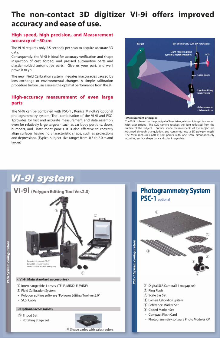
<Measurement principle>The VI-9i is based on the principal of laser triangulation. A target is scannedwith laser stripes . The CCD camera receives the light reflected from thesurface of the subject. Surface shape measurements of the subject areobtained through triangulation, and converted into a 3D polygon mesh.The VI-9i measures 640 x 480 points with one scan, simultaneouslyacquiring surface shape data and color image data.
Galvanometer- driven mirror
Light-receiving lenssystem (Interchangeable)
Target
Light-emittinglens system
Laser beam
CCD
Set of filters (R, G, B, BP, rotatable)
VI-
9iS
yste
mco
nfi
gu
rati
on
PSC
-1Sy
stem
con
fig
ura
tio
n
< VI-9i Main standard accessories>
q Interchangeable Lenses (TELE, MIDDLE, WIDE)
w Field Calibration System
• Polygon editing software “Polygon Editing Tool ver.2.0”
• SCSI Cable
<Optional accessories>
e Tripod Set
• Rotating Stage Set
∗ Shape varies with sales region.
q Digital SLR Camera(14 megapixel)
w Ring Flash
e Scale Bar Set
r Camera Calibration System
t Reference Marker Set
y Coded Marker Set
• Compact Flash Card
• Photogrammetry software Photo Modeler KM
VI-9i (Polygon Editing Tool Ver.2.0) Photogrammetry SystemPSC-1 optional
Computer (not included ; PC-AT
Compatible computer running
Windows 2000 or Windows XP required)
The non-contact 3D digitizer VI-9i offers improvedaccuracy and ease of use.High speed, high precision, and Measurementaccuracy of ±50µm
The VI-9i requires only 2.5 seconds per scan to acquire accurate 3Ddata.Consequently, the VI-9i is ideal for accuracy verification and shapeinspection of cast, forged, and pressed automotive parts andplastic-molded automotive parts. Give us your part, and we’llprove it to you.
The new Field Calibration system, negates inaccuracies caused bylens exchange or environmental changes. A simple calibrationprocedure before use assures the optimal performance from the 9i.
High-accuracy measurement of even largeparts
The VI-9i can be combined with PSC-1 , Konica Minolta’s optionalphotogrammetry system. The combination of the VI-9i and PSC-1provides for fast and accurate measurement and data assemblyeven for relatively large targets - such as car body portions, doors,bumpers, and instrument panels. It is also effective to correctlyalign surfaces having no characteristic shape, such as projectionsand depressions. (Typical subject size ranges from 0.5 to 2.0 m andlarger)
VI-9i system

AAEEIIAAPPKK Printed in Japan9242-4892-21©2004 KONICA MINOLTA SENSING, INC. 1
The manufacturing center of Konica Minolta SensingInc. (Location: Aichi Pref., Japan) was approved by theBritish certification organization Lloyd’s Register QualityAssurance for certification under the ISO 9001: 1994international quality management system standards onMarch 3, 1995. Since its establishment in 1990, thecenter has carried out the development and productionof precision instruments and associated applicationsoftware for the measurement of color, light, and shape.Certification was awarded to the center’s qualitymanagement system, including design, manufacturer,management of manufacture, calibration andservicing.Certification was carried over to the ISO 9001:2000 standards in February, 2003.
CERTIFIED
SAFETY PRECAUTIONSRead all safety and operating instructionsbefore operating the VI-9i.
Use only a power source of thespecified rating.Improper connection may cause afire or electric shock.Do not stare into the laser beam.(MAX. 30mW 690nm / CLASS 1(FDA), CLASS 2 (IEC) LASERPRODUCT)
Type Non-contact 3D digitizerMeasuring Method Triangulation light block methodLight-Receiving Lenses (Interchangeable) TELE Focal distance f=25 mm
MIDDLE Focal distance f=14 mmWIDE Focal distance f=8 mm
Scan Range 0.6 to 1.0 m (In Standard mode)0.5 to 2.5 m (In Extended mode)
Laser Scan Method Galvanometer-driven rotating mirrorLaser Class Class 2 (IEC60825-1), Class 1 (FDA)X Direction Input Range(In Extended mode) TELE 93 to 463 mm
MIDDLE 165 to 823 mmWIDE 299 to 1495 mm
Y Direction Input Range(In Extended mode) TELE 69 to 347 mmMIDDLE 124 to 618 mmWIDE 224 to 1121 mm
Z Direction Input Range(In Extended mode) TELE 26 to 680 mmMIDDLE 42 to 1100 mmWIDE 66 to 1750 mm
Accuracy (X, Y, Z) ±0.05 mm (Using TELE lens at distance of 0.6 m, with Field Calibration System, Konica Minolta’s standard, at 20°C)Precision (Z, σ ) 0.008 mm (Using TELE lens at distance of 0.6 m, Konica Minolta’s standard, at 20°C)Input Time (per scan) 2.5 secTransfer Time to Host Computer Approx. 1.5 secAmbient Lighting Condition Office environment, 500 lx or lessImaging Element 3D data: 1/3-inch frame transfer CCD (340,000 pixels)
Color data: Common with 3D data (color separation by rotary filter)Number of Output Pixels 3D data/Color data: 640 x 480Output Format 3D data: Konica Minolta format, & (STL, DXF, OBJ, ASCII points, VRML)
(Converted to 3D data by the Polygon Editing Software/ standard accessory)Color data: RGB 24-bit raster scan data
Data File Size Total 3D and color data capacity: 3.6MB per dataViewfinder 5.7-inch LCD (320 x 240 pixels)Output Interface SCSI II (DMA synchronous transfer)Power Commercial AC power, 100 to 240 V (50/60Hz), rated current 0.6 A (at 100 VAC)Dimensions 221 (W) x 412 (H) x 282 (D) mmWeight Approx. 15 kg (with lens attached)Operating temperature/humidity range 10°C to 40°C, relative humidity 65% or less with no condensationStorage temperature/humidity range 0°C to 40°C, relative humidity 85% or less (at 35°C) with no condensationRegulatory approvals UL 61010A-1, CSA-C22.2 No.1010-1, etc.
Specifications of Polygon Editing Tool ver. 2.0
<Main Features>Readable Formats Konica Minolta proprietary formats: CAM, VVD, SCN, CDM, CDK
General format: STLData Conversion Conversion from Konica Minolta proprietary formats into general format
Polygonal data: DXF, Wavefront, Softimage, VRML 2.0, STL, MGFPoint group data: ASCII
Functions Data alignment, data merging, smoothing, uniform data reduction,adaptive data reduction, polygon check, texture blending
Point Group Editing Rotation, movement, deletion, hole filling with data interpolationCamera Remote Operation Measurement, measurement reference distance setting, number of
scans setting, laser power setting, high-quality setting, filter setting,etc.
Display Modes Wireframe, shading, texture mapping
<Operating Environment>PC-AT compatible Computer running Windows®2000/Windows®XPOS Windows®2000 Professional (Service Pack 2 or higher)
Windows®XP Professional (Service Pack 1 or higher)CPU Pentium III or betterRAM 512 MB (1024 MB recommended)Display Graphic display ability at 1024 x 768 or moreGraphics Board OpenGL-ready board
(verified-compatible board recommended.)SCSI Interface Adaptec SCSI card
(Please use a verified compatible board.)Others CD-ROM drive, USB port
For further information regarding graphics board and SCSI interface,please contact the VI Salesperson in your area.
Specifications of Photogrammetry System PSC-1Typical Subject Size 0.5 to 2.0 mAccuracy ±0.1 mm for volume <2 m3 and below (Measurement subject size : 1 m, Photogrammetry alone, Konica Minolta's standard, at 20°C)
Specifications of VI-9i
• Specifications are subject to change without notice.• Product names in this brochure are trademarks of their respective companies.
3-91, Daisennishimachi, Sakai. Osaka 590-8551, Japan
EMail : [email protected]. pWeb : http://// konicaminolta.j. p/pr/se_3d
Konica Minolta Photo Imaging Europe GmbH Europaallee 17, 30855 Langenhagen, Germany Phone: +49 (0)5 11/74 04-845 FAX: +49 (0)5 11/74 04-807EMail : [email protected] : www.konicaminolta-3d.com