Embed Size (px)
Citation preview
A member of
Dammam, 2nd Industrial Area Saudi ArabiaP.O. Box 1594 - Al khobar 31952Tel: +9663 81 25555Fax: +9663 81 25555Email: [email protected]
Bina AdvancedConcrete Products Factory

your
is Our VisionDream
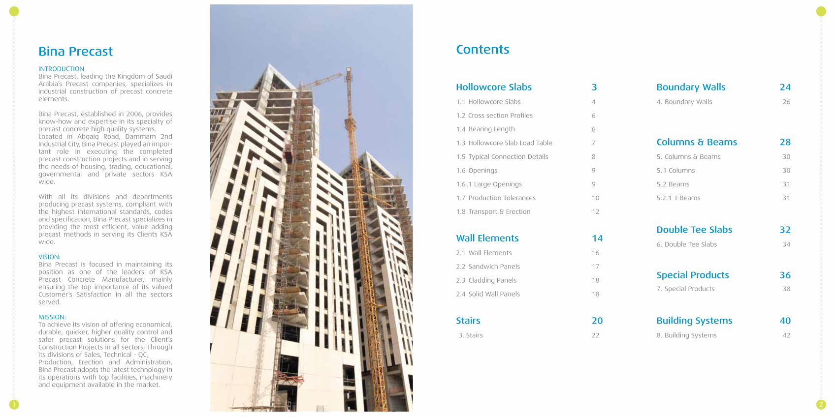
Bina PrecastINTRODUCTIONBina Precast, leading the Kingdom of Saudi Arabia’s Precast companies, specializes in industrial construction of precast concrete elements.
Bina Precast, established in 2006, provides know-how and expertise in its specialty of precast concrete high quality systems.Located in Abqaiq Road, Dammam 2nd Industrial City, Bina Precast played an impor-tant role in executing the completed precast construction projects and in serving the needs of housing, trading, educational, governmental and private sectors KSA wide.
With all its divisions and departments producing precast systems, compliant with the highest international standards, codes and specification, Bina Precast specializes in providing the most efficient, value adding precast methods in serving its Clients KSA wide.
VISION:Bina Precast is focused in maintaining its position as one of the leaders of KSA Precast Concrete Manufacturer, mainly ensuring the top importance of its valued Customer’s Satisfaction in all the sectors served.
MISSION:To achieve its vision of offering economical, durable, quicker, higher quality control and safer precast solutions for the Client’s Construction Projects in all sectors; Through its divisions of Sales, Technical - QC, Production, Erection and Administration, Bina Precast adopts the latest technology in its operations with top facilities, machinery and equipment available in the market.
1
3
4
6
6
7
8
9
9
10
12
14
16
17
18
18
20
3. 22
Hollowcore Slabs
1.1 Hollowcore Slabs
1.2
1.4
Hollowcore Slab Load Table
Cross section Profiles
1.3
Bearing Length
1.5 Typical Connection Details
1.6 Openings
1.6 .1 Large Openings
1.7 Production Tolerances
1.8 Transport & Erection
Wall Elements
2.1 Wall Elements
2.2 Sandwich Panels
2.3 Cladding Panels
2.4 Solid Wall Panels
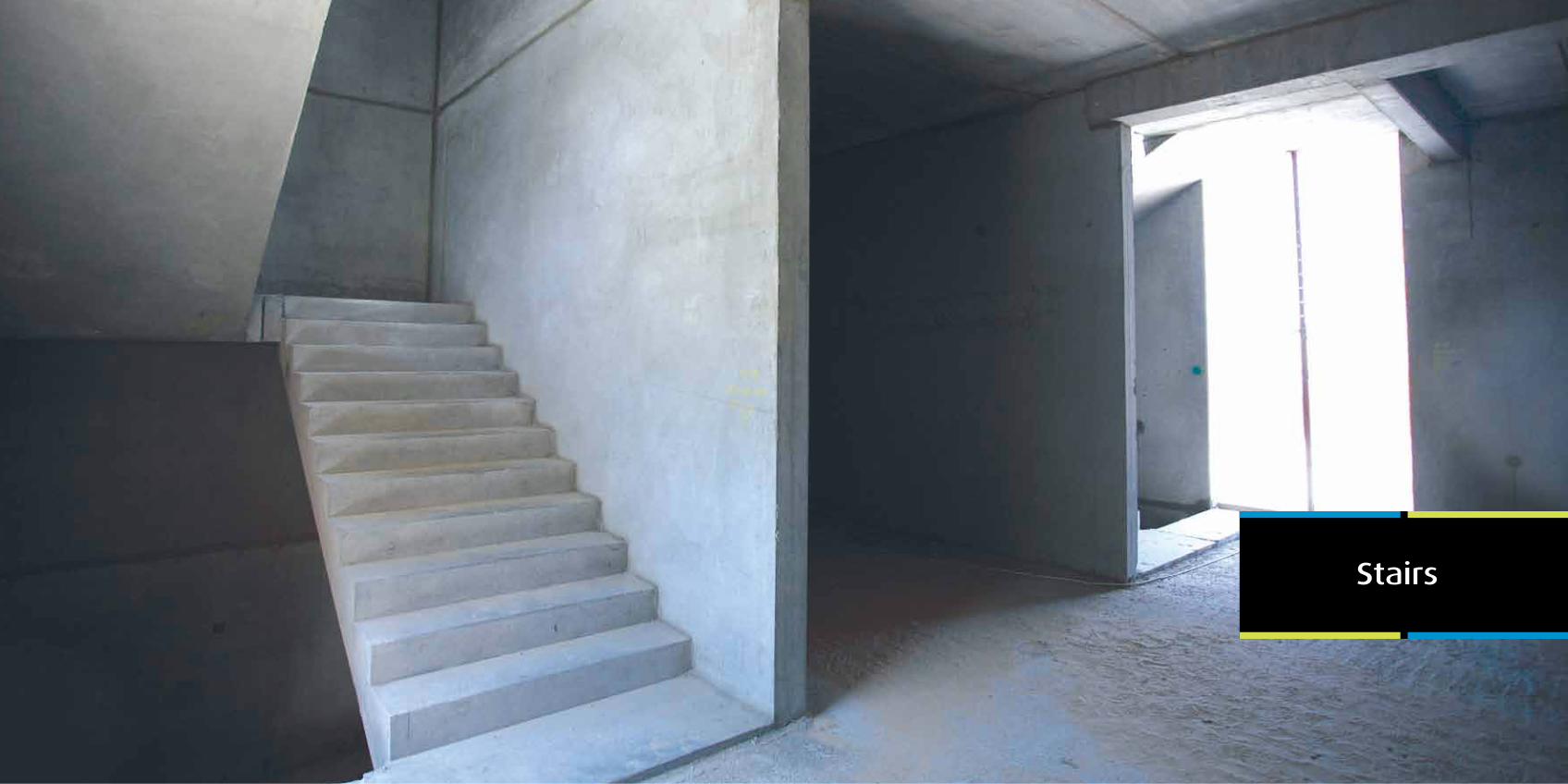
Stairs
Stairs
Contents
Boundary Walls 24
4. Boundary Walls 26
Columns & Beams 28
5. Columns & Beams 30
5.1 Columns 30
5.2 Beams 31
5.2.1 I-Beams 31
32
6. Double Tee Slabs 34
Double Tee Slabs
Special Products7. Special Products 38
36
Building Systems 40
8. Building Systems 42
2
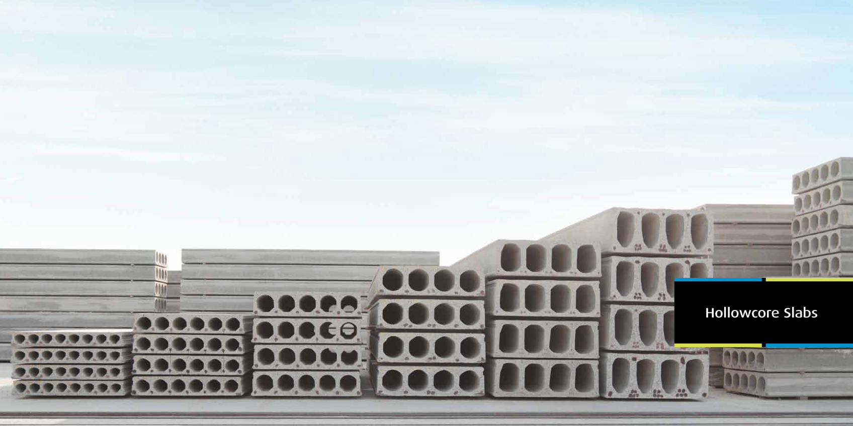
Hollowcore Slabs
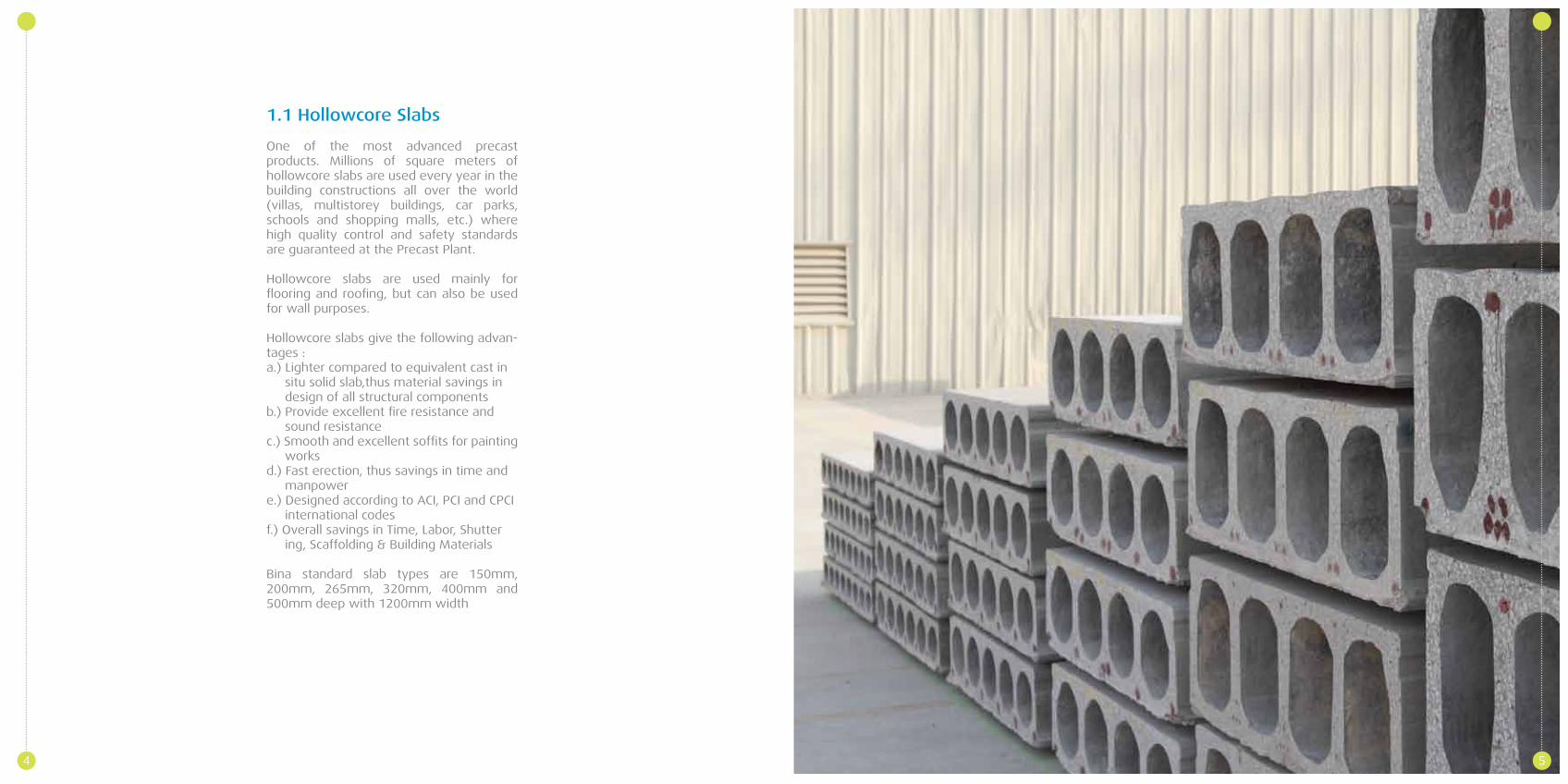
1.1 Hollowcore Slabs
One of the most advanced precast products. Millions of square meters of hollowcore slabs are used every year in the building constructions all over the world (villas, multistorey buildings, car parks, schools and shopping malls, etc.) where high quality control and safety standards are guaranteed at the Precast Plant.
Hollowcore slabs are used mainly for flooring and roofing, but can also be used for wall purposes.
Hollowcore slabs give the following advan-tages :a.) Lighter compared to equivalent cast in situ solid slab,thus material savings in design of all structural componentsb.) Provide excellent fire resistance and sound resistancec.) Smooth and excellent soffits for painting worksd.) Fast erection, thus savings in time and manpowere.) Designed according to ACI, PCI and CPCI international codesf.) Overall savings in Time, Labor, Shutter ing, Scaffolding & Building Materials
Bina standard slab types are 150mm, 200mm, 265mm, 320mm, 400mm and 500mm deep with 1200mm width
4 5
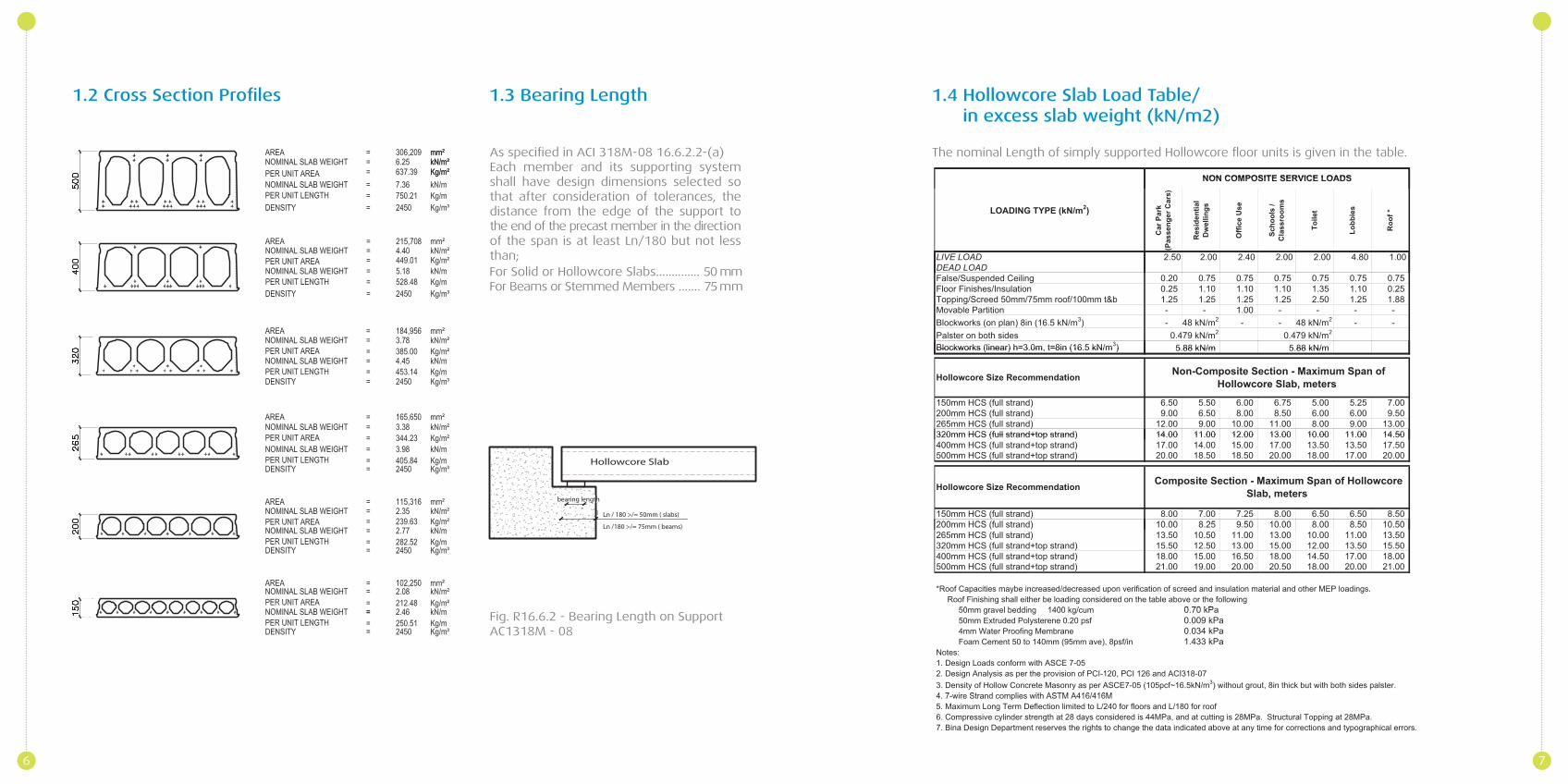
As specified in ACI 318M-08 16.6.2.2-(a) Each member and its supporting system shall have design dimensions selected so that after consideration of tolerances, the distance from the edge of the support to the end of the precast member in the direction of the span is at least Ln/180 but not less than;
1.2 Cross Section Profiles 1.3 Bearing Length 1.4 Hollowcore Slab Load Table/ in excess slab weight (kN/m2)
Fig. R16.6.2 - Bearing Length on SupportAC1318M - 08
The nominal Length of simply supported Hollowcore floor units is given in the table.
6 7
Hollowcore Slab
Ln / 180 >/= 50mm ( slabs)
Ln /180 >/= 75mm ( beams)
bearing length
For Solid or Hollowcore Slabs.............. 50 mmFor Beams or Stemmed Members ....... 75 mm
1.6 Openings
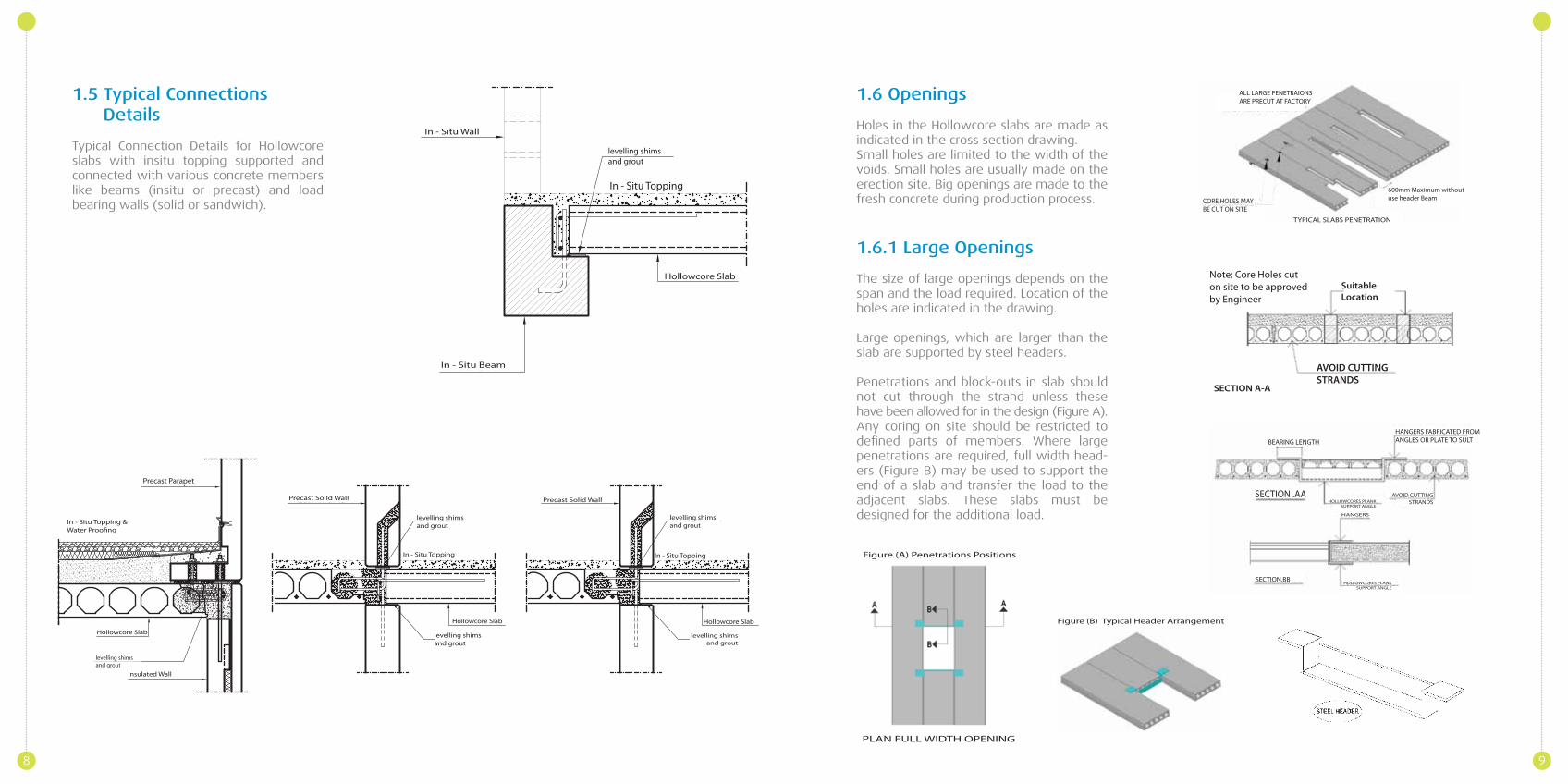
Holes in the Hollowcore slabs are made as indicated in the cross section drawing.Small holes are limited to the width of the voids. Small holes are usually made on the erection site. Big openings are made to the fresh concrete during production process.
1.6.1 Large Openings
The size of large openings depends on the span and the load required. Location of the holes are indicated in the drawing.
Large openings, which are larger than the slab are supported by steel headers.
Penetrations and block-outs in slab should not cut through the strand unless these have been allowed for in the design (Figure A). Any coring on site should be restricted to defined parts of members. Where large penetrations are required, full width head-ers (Figure B) may be used to support the end of a slab and transfer the load to the adjacent slabs. These slabs must be designed for the additional load.
1.5 Typical Connections Details
Typical Connection Details for Hollowcore slabs with insitu topping supported and connected with various concrete members like beams (insitu or precast) and load bearing walls (solid or sandwich).
8 9
PLAN FULL WIDTH OPENING
Figure (A) Penetrations Positions
Figure (B) Typical Header Arrangement
Insulated Wall
levelling shimsand grout
Hollowcore Slab
In - Situ Topping &
Precast Parapet
Precast Soild Wall
levelling shimsand grout
In - Situ Topping
levelling shimsand grout
Hollowcore Slab
Precast Solid Wall
levelling shimsand grout
In - Situ Topping
Hollowcore Slab
levelling shimsand grout
levelling shimsand grout
In - Situ Topping
Hollowcore Slab
In - Situ Beam
In - Situ Wall
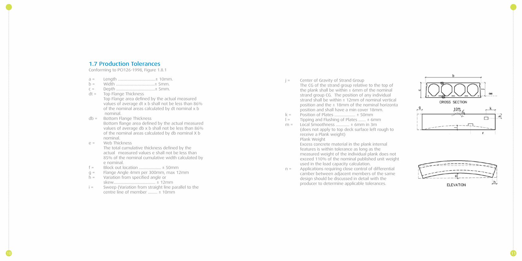
1.7 Production Tolerances
a = Length …………………………..….± 10mm.b = Width ……………………………….± 5mm.c = Depth ……………………………….± 5mm.dt = Top Flange Thickness Top Flange area defined by the actual measured values of average dt x b shall not be less than 86% of the nominal areas calculated by dt nominal x b nominal.db = Bottom Flange Thickness Bottom flange area defined by the actual measured values of average db x b shall not be less than 86% of the nominal areas calculated by db nominal X b nominal.e = Web Thickness The total cumulative thickness defined by the actual measured values e shall not be less than 85% of the nominal cumulative width calculated by e nominal.f = Block out location ………………… ± 50mmg = Flange Angle 4mm per 300mm, max 12mmh = Variation from specified angle or skew…………………………….…… ± 12mmi = Sweep (Variation from straight line parallel to the centre line of member ……… ± 10mm
j = Center of Gravity of Strand Group The CG of the strand group relative to the top of the plank shall be within ± 6mm of the nominal strand group CG. The position of any individual strand shall be within ± 12mm of nominal vertical position and the ± 18mm of the nominal horizonta position and shall have a min cover 18mm.k = Position of Plates ……………….. ± 50mml = Tipping and Flushing of Plates ……. ± 6mmm = Local Smoothness …………. ± 6mm in 3m (does not apply to top deck surface left rough to receive a Plank weight) Plank Weight Excess concrete material in the plank internal features is within tolerance as long as the measured weight of the individual plank does not exceed 110% of the nominal published unit weight used in the load capacity calculation.n = Applications requiring close control of differential camber between adjacent members of the same design should be discussed in detail with the producer to determine applicable tolerances.
Conforming to PCI126-1998, Figure 1.8.1
10 11
12 13
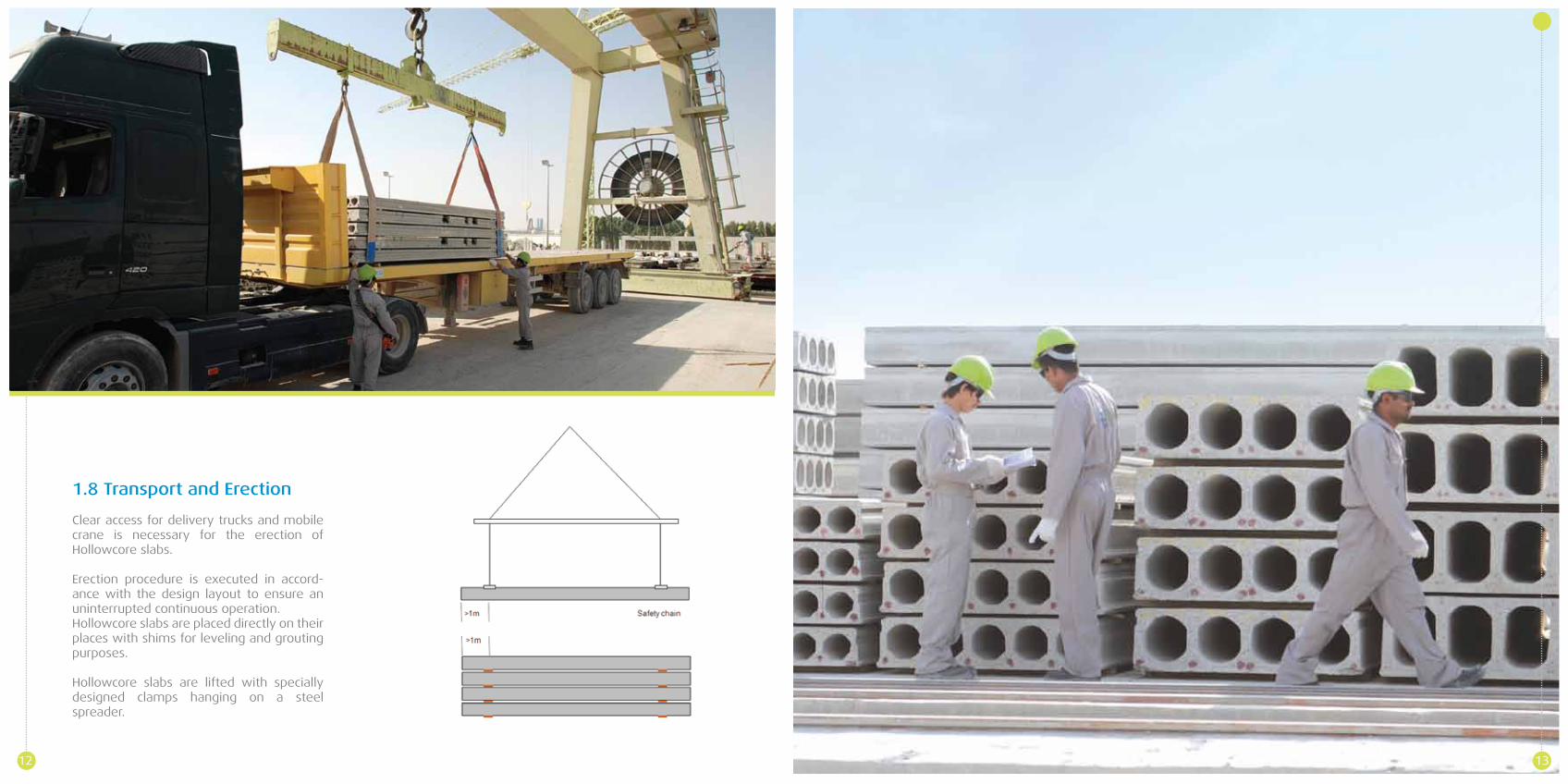
1.8 Transport and Erection
Clear access for delivery trucks and mobile crane is necessary for the erection of Hollowcore slabs. Erection procedure is executed in accord-ance with the design layout to ensure an uninterrupted continuous operation.Hollowcore slabs are placed directly on their places with shims for leveling and grouting purposes.
Hollowcore slabs are lifted with specially designed clamps hanging on a steel spreader.

Wall Elements
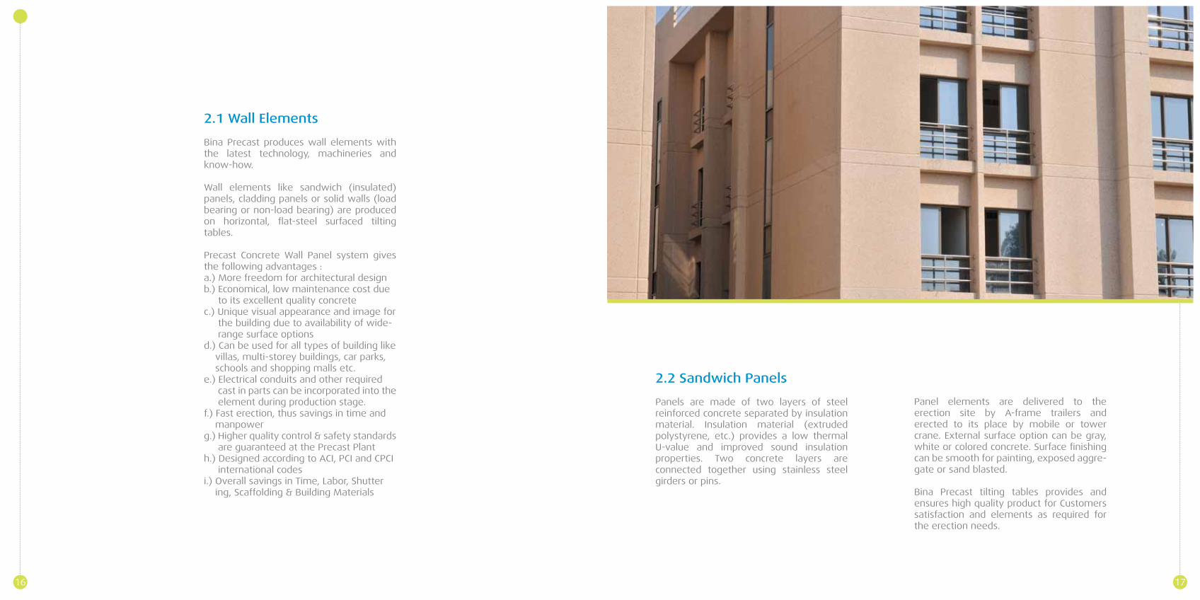
2.2 Sandwich Panels
Panels are made of two layers of steel reinforced concrete separated by insulation material. Insulation material (extruded polystyrene, etc.) provides a low thermal U-value and improved sound insulation properties. Two concrete layers are connected together using stainless steel girders or pins.
Panel elements are delivered to the erection site by A-frame trailers and erected to its place by mobile or tower crane. External surface option can be gray, white or colored concrete. Surface finishing can be smooth for painting, exposed aggre-gate or sand blasted.
Bina Precast tilting tables provides and ensures high quality product for Customers satisfaction and elements as required for the erection needs.
2.1 Wall Elements
Bina Precast produces wall elements with the latest technology, machineries and know-how.
Wall elements like sandwich (insulated) panels, cladding panels or solid walls (load bearing or non-load bearing) are produced on horizontal, flat-steel surfaced tilting tables.
Precast Concrete Wall Panel system gives the following advantages :a.) More freedom for architectural designb.) Economical, low maintenance cost due to its excellent quality concretec.) Unique visual appearance and image for the building due to availability of wide- range surface optionsd.) Can be used for all types of building like villas, multi-storey buildings, car parks, schools and shopping malls etc.e.) Electrical conduits and other required cast in parts can be incorporated into the element during production stage.f.) Fast erection, thus savings in time and manpowerg.) Higher quality control & safety standards are guaranteed at the Precast Planth.) Designed according to ACI, PCI and CPCI international codesi.) Overall savings in Time, Labor, Shutter ing, Scaffolding & Building Materials
16 17
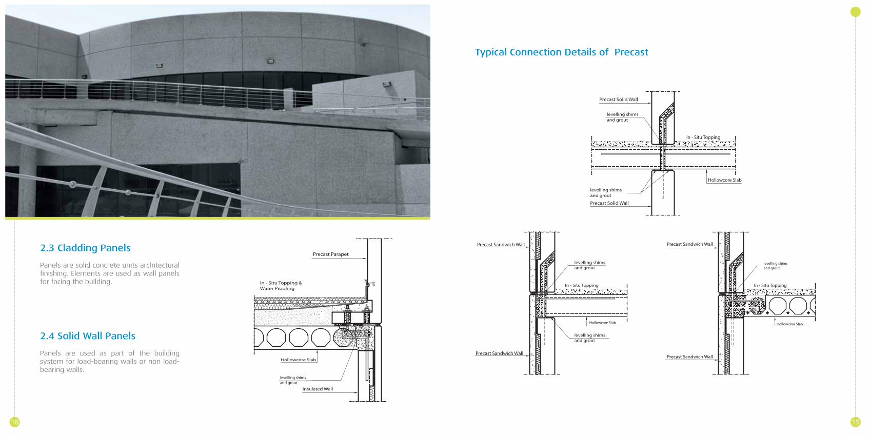
2.3 Cladding Panels
Panels are solid concrete units architectural finishing. Elements are used as wall panels for facing the building.
2.4 Solid Wall Panels
Panels are used as part of the building system for load-bearing walls or non load-bearing walls.
Typical Connection Details of Precast
18 19
Stairs
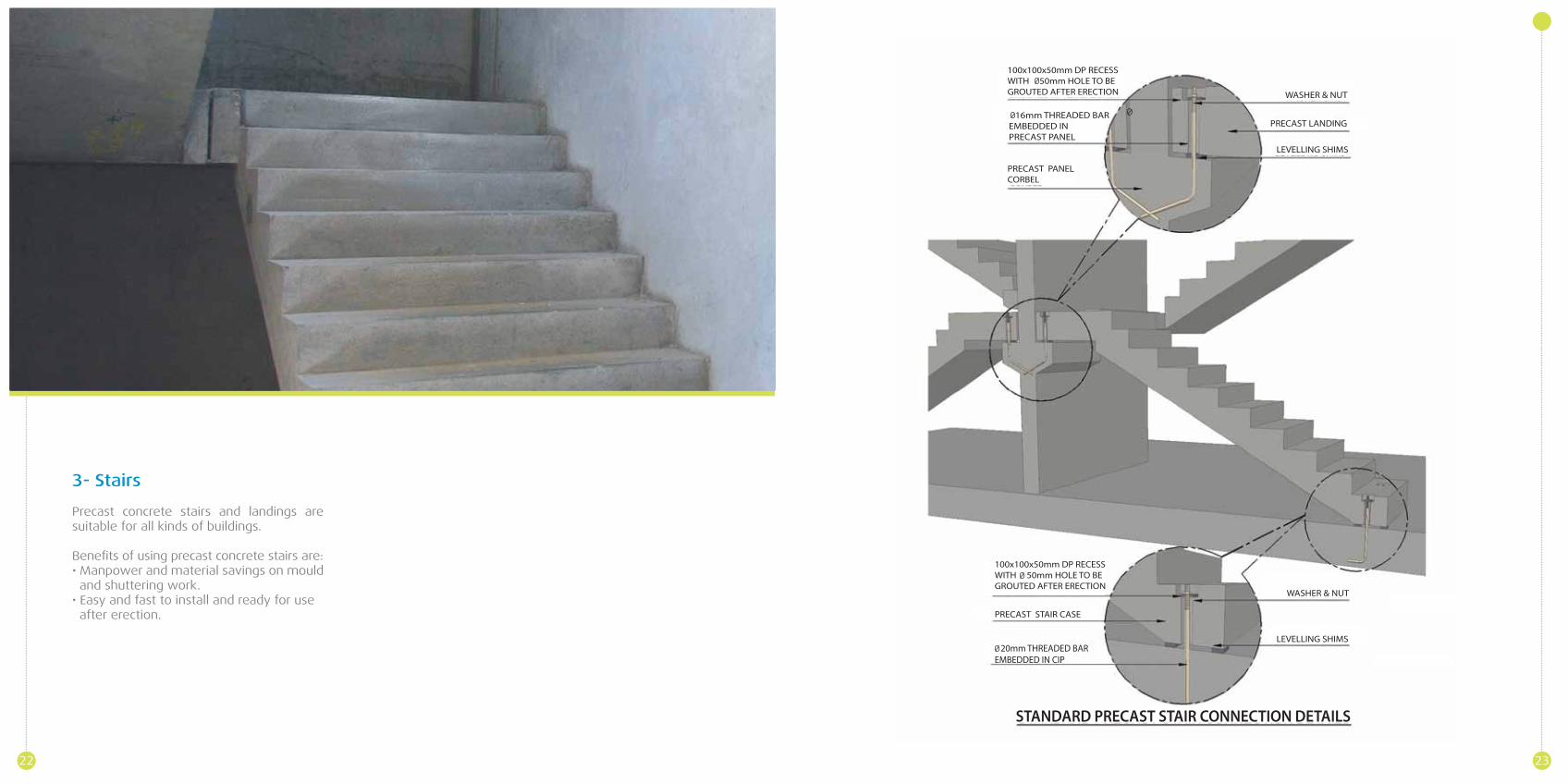
3- Stairs
Precast concrete stairs and landings are suitable for all kinds of buildings.
Benefits of using precast concrete stairs are:• Manpower and material savings on mould and shuttering work.• Easy and fast to install and ready for use after erection.
22 23
Boundary Walls
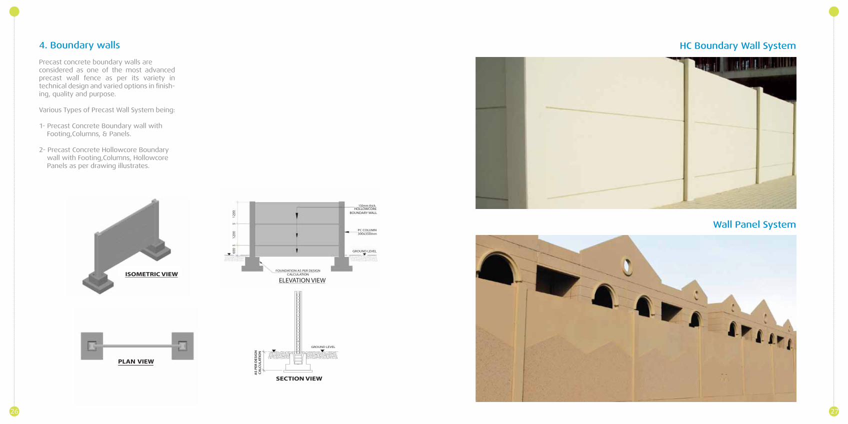
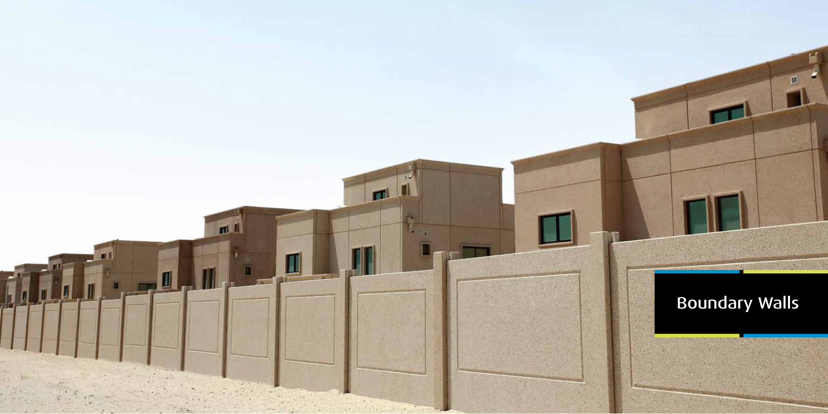
4. Boundary walls
Precast concrete boundary walls are considered as one of the most advanced precast wall fence as per its variety in technical design and varied options in finish-ing, quality and purpose.
Various Types of Precast Wall System being:
1- Precast Concrete Boundary wall with Footing,Columns, & Panels.
2- Precast Concrete Hollowcore Boundary wall with Footing,Columns, Hollowcore Panels as per drawing illustrates.
Wall Panel System
26 27
HC Boundary Wall System
Columns& Beams
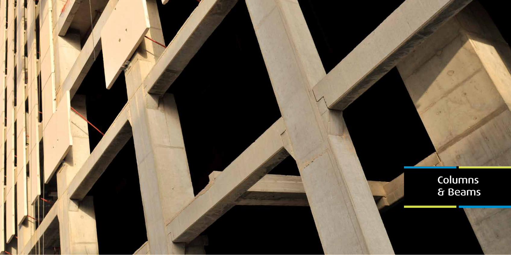
5. Columns & Beams
Precast concrete columns and beams provide advantages in designing buildings for shopping malls, schools, warehouse etc.
Long span precast columns and beams provide benefits for large open area struc-ture. Precast beams can be designed and produced using ordinary reinforced concrete or prestressed concrete.
Precast components are delivered by trailers to the erection site for installation.
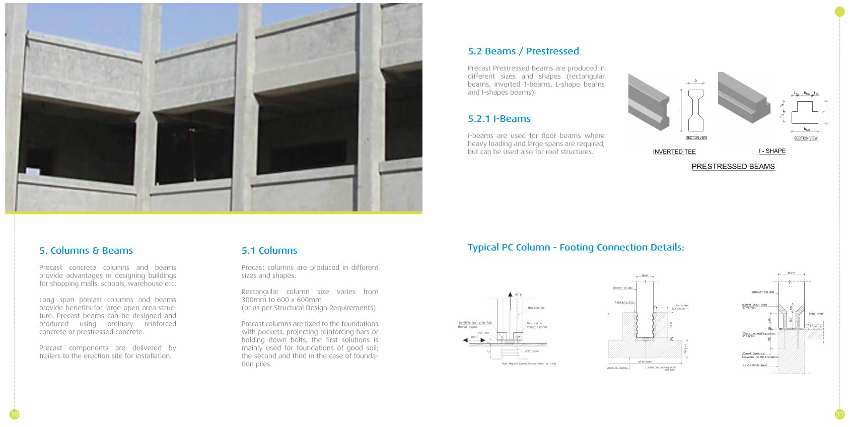
5.1 Columns
Precast columns are produced in different sizes and shapes.
Rectangular column size varies from 300mm to 600 x 600mm (or as per Structural Design Requirements)
Precast columns are fixed to the foundations with pockets, projecting reinforcing bars or holding down bolts, the first solutions is mainly used for foundations of good soil; the second and third in the case of founda-tion piles.
5.2 Beams / Prestressed
Precast Prestressed Beams are produced in different sizes and shapes (rectangular beams, inverted T-beams, L-shape beams and I-shapes beams).
5.2.1 I-Beams
I-beams are used for floor beams where heavy loading and large spans are required, but can be used also for roof structures.
Typical PC Column - Footing Connection Details:
30 31
Double TeeSlabs
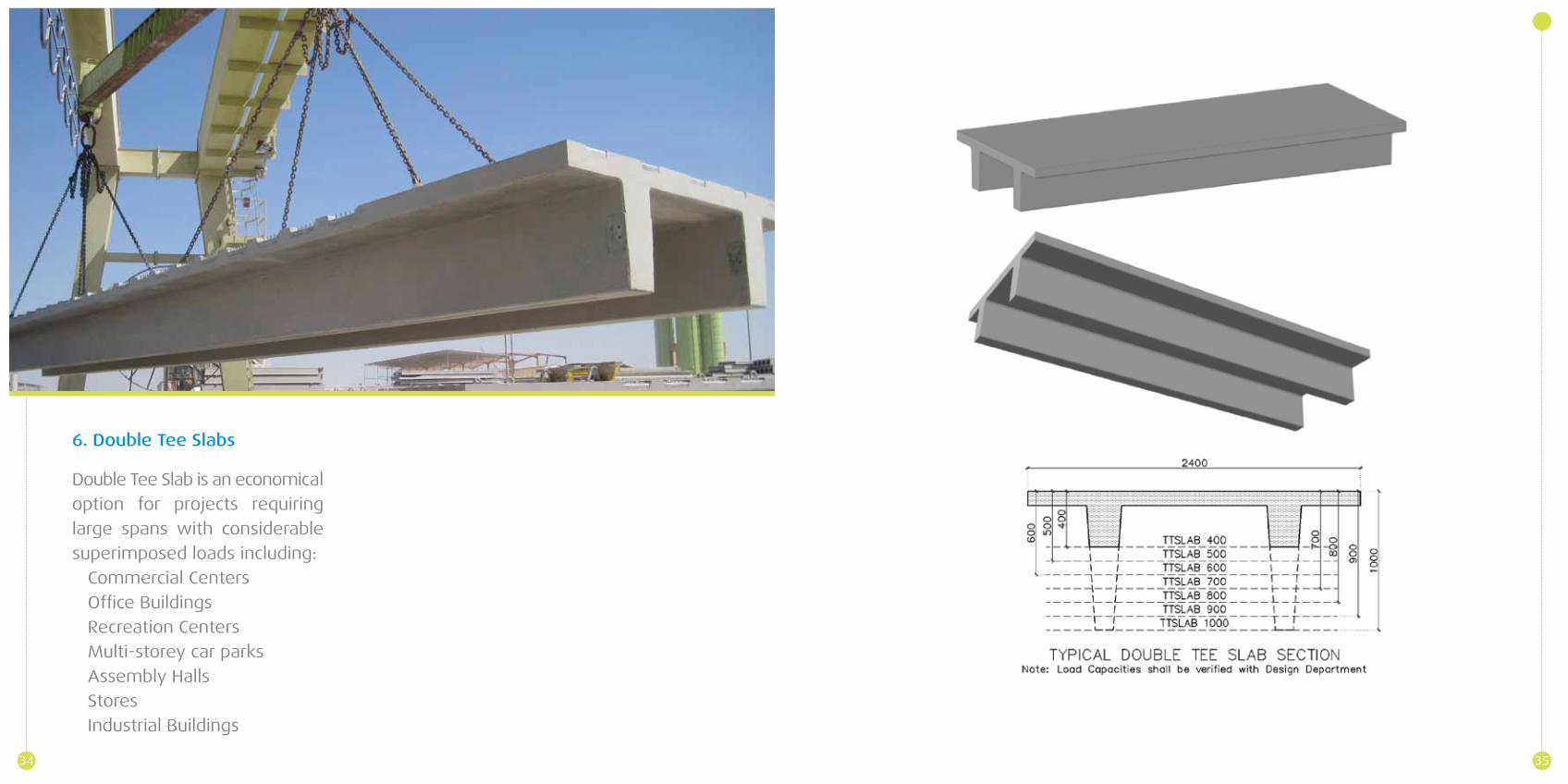
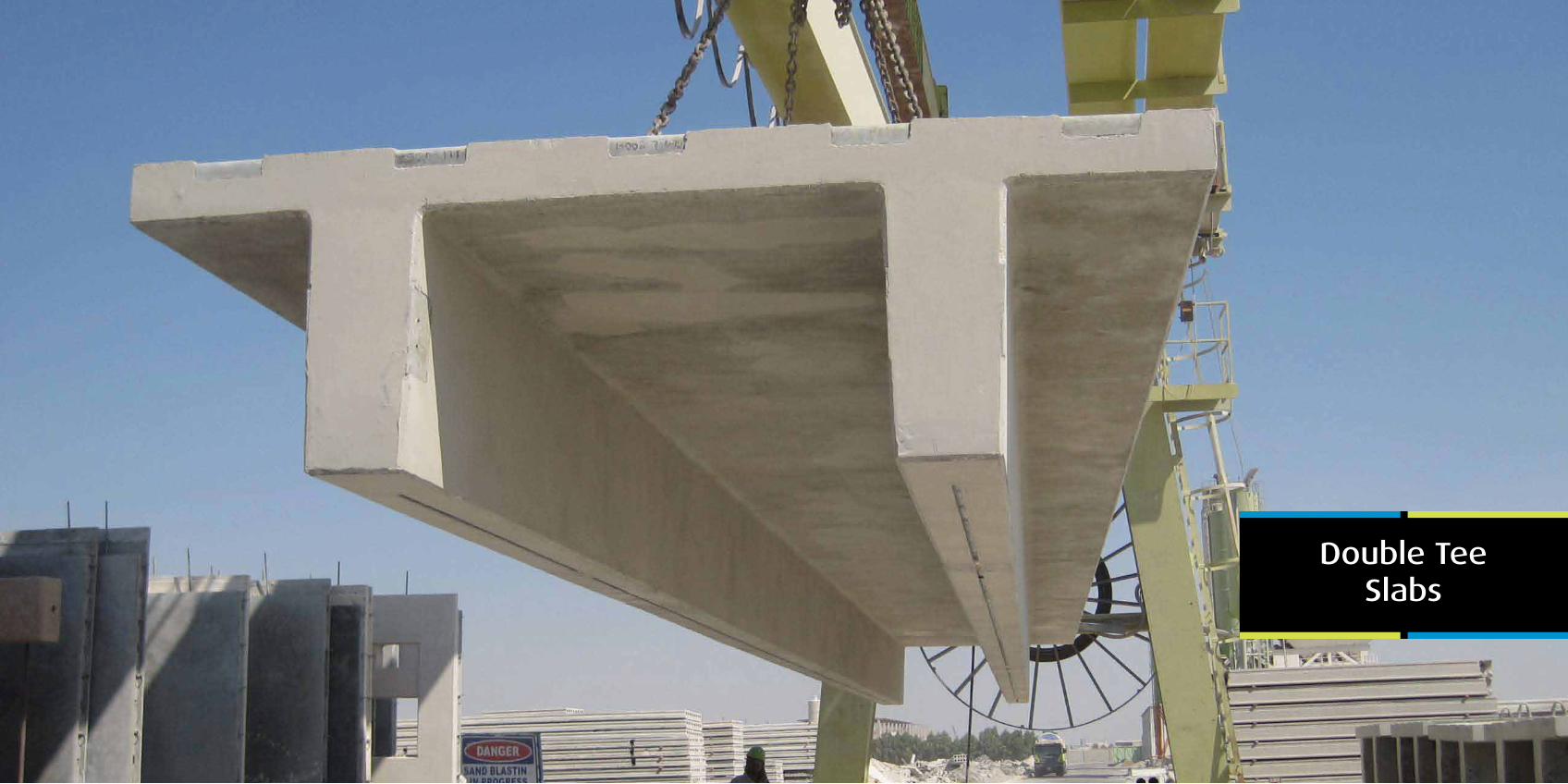
6. Double Tee Slabs
Double Tee Slab is an economical
option for projects requiring
large spans with considerable
superimposed loads including:
Commercial Centers
Office Buildings
Recreation Centers
Multi-storey car parks
Assembly Halls
Stores
Industrial Buildings
34 35
SpecialProducts
2
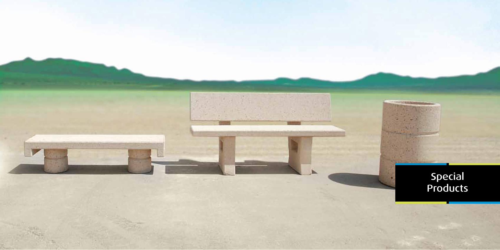
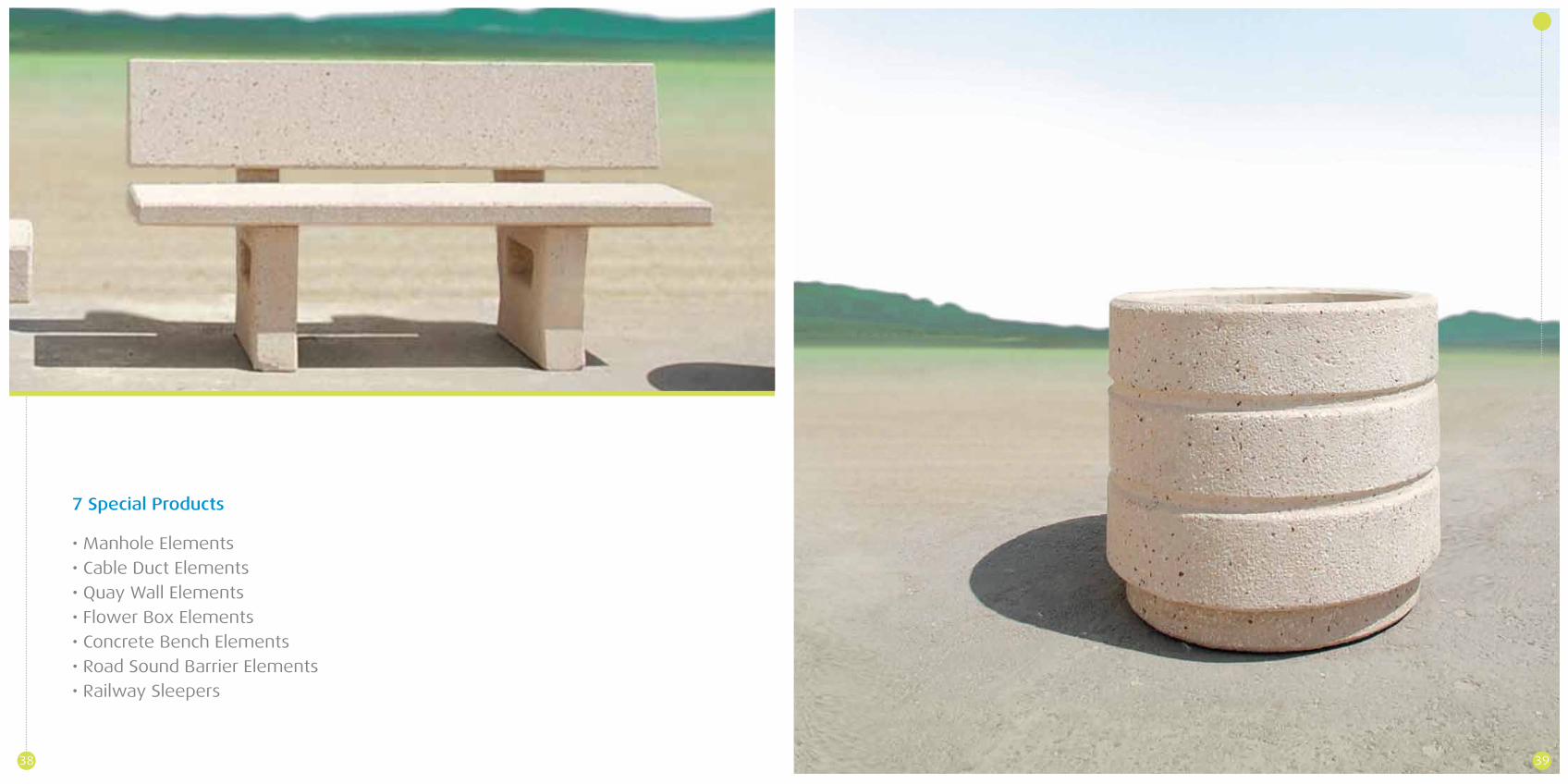
7 Special Products
• Manhole Elements
• Cable Duct Elements
• Quay Wall Elements
• Flower Box Elements
• Concrete Bench Elements
• Road Sound Barrier Elements
• Railway Sleepers
38 39
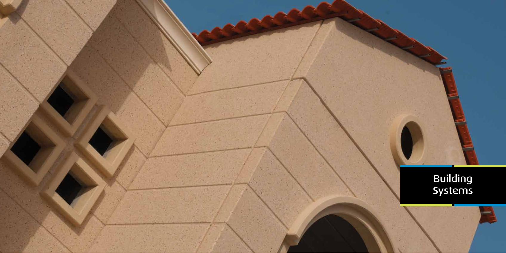
BuildingSystems
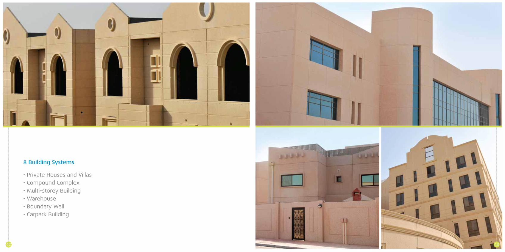
8 Building Systems
• Private Houses and Villas
• Compound Complex
• Multi-storey Building
• Warehouse
• Boundary Wall
• Carpark Building
42 43


![[3] Silabus Bina 5](https://img.pdfslide.us/doc/110x75/577c811f1a28abe054ab91be/3-silabus-bina-5.jpg)