Embed Size (px)
Citation preview
BIM BASED CLASH DETECTION APPLICATIONS: POTENTIALS AND 1
OBSTACLES 2
3
Mohamed Magdy Nour1 4
1Assocaite Professor, Architecture Department, Faculty of Fine Arts, Helwan University, 5
EGYPT. 6
7
8
9
10
11
ABSTRACT
Clash detection is a main advantage for using BIM
technology. Despite the fact that there are already
existing efforts and software tools in this domain, it
has reached a plateau; where the flexibility of
defining and managing clashes and performing
accurate geometrical clash detection represents a
main obstacle that hinders further developments in
such a domain.
This paper addresses both the semantics as well as
the geometrical aspects of BIM clash detection. It
presents the potential of available algorithms and
technologies to perform such operations in order to
enhance such BIM functionality with relevance to
end users as well as software developers.
An easy to trace prototype is used to demonstrate
some of such functionalities based on an IFC Java
toolbox and a Java3D viewer that are developed by
the author.
Furthermore, this paper presents potential
interoperability benefits that can be gained and puts
forward some guidelines for the further development
in this domain.
INTRODUCTION
This study addresses the problem of clash detection
based on the BIM technology among same and cross
disciplines in the Architectural, Engineering,
Construction and Facilities Management industries
(AEC-FM). It differentiates between the different
levels of BIM implementation and discusses the need
for clash detection for the coordination between
AEC-FM disciplines, especially at the detailed design
and shop drawings stages.
The paper discusses the role of open BIM and its
relevance to this research. It then shifts to the
definition of clash detection and its sub-categories.
The role of the IFC BIM model as a standard BIM
data structure is discussed with special emphasis on
its semantics and topological advantages that can aid
clash detection.
The paper presents some novel approaches to shift
the simple geometrical clash detection process
between BIM objects to more generic conflict
detection approach that is relevant to high-level BIM
implementations.
An IFC Java3D based prototype is developed for
testing some of the algorithms for clash detection to
demonstrate the complexity of the problem and the
potentials for further developing the current practice
of the BIM clash detection processes.
BIM
A main advantage of the Building Information
Modelling (BIM) technology is its ability to
incorporate disciplines together in a single model. It
is supposed that this core model should be used by all
software applications through data sharing, i.e.
interoperability. All data should be structured around
construction objects within a single Object Oriented
Model. Furthermore, this technology should enable
multi-disciplinary team working functionalities to be
conducted on the same model and thus should
implement an Object Versioning System for its
workflow. (Nour & Beucke, 2010).
However, the majority of the current practises of
BIM applications do not implement a perfect
workflow as described above. It often depends on
data exchange rather than data sharing. Furthermore,
the migration from 2D CAD to high-level BIM
implementations is still on its way. This has led some
national institution to categorize BIM levels of
implementations into four levels (from zero to three).
(NBS, 2014a).
“Level zero BIM” has no collaboration. 2D CAD
drafting is used for Production Information (RIBA,
2013). The main output and collaboration form is via
paper or electronic prints, or a mixture of both.
However, the majority of the industry is already
ahead of this now (NBS, 2014b).
“Level one BIM” consists of a mixture of 3D CAD
for concept work, and 2D for drafting of statutory
approval documentation and Production Information.
CAD standards are managed according to (BS1192,
2007), and electronic sharing (exchange) of data is
carried out from a common data environment (CDE).
This represents the current practice of many
organizations today.
“Level two BIM” is characterized by collaborative
working. Design information is shared (exchanged)
through a common file format, which enables any
organisation to be able to combine that data with
their own in order to make a federated BIM model,
and to carry out interrogative checks on it. Hence any
CAD software that each party used must be capable
of exporting to one of the common file formats such
as IFC (Industry Foundation Class) (ISO:16739,
2013) or COBie (Construction Operations Building
Information Exchange) (East, 2007). This is the
method of working that has been set as a minimum
target by the UK government for all work on public-
sector work, by 2016.
“Level three BIM” represents full collaboration
between all disciplines by means of using a single,
shared project model that is held in a centralized
repository. All parties can access and modify that
same model independent form any software vendor
or proprietary application. The benefit is that it
removes the final layer of risk for conflicting
information. This is known as ‘Open BIM’, and the
UK government’s target date for public-sector
working is 2019.
As it can be concluded from the above BIM
implementation levels’ categorization, a main
functionality for the BIM technology is the ability to
perform the so called “clash detection” to ensure the
consistency of the single core model among all
disciplines and thus reaching level three BIM.
There are several commercial BIM based clash
detection software tools available on the market like
Solibri Model Checker (Solibri, 2016), Navisworks
(Navisworks, 2016) , Tekla Structures (Tekla, 2016),
and VICO Software (VICO, 2016)… . They do not
reveal their clash detection algorithms or internal
way of working. They are considered as black box
technologies. Furthermore, it is not easy to formulate
a tailored clash detection process, for certain objects
with certain conditions depending upon BIM objects’
attributes and property sets as well as their geometry
and topology. This is attributed to the fact that they
do not support an open standard query mechanism
(language) that is capable of defining sets and sub-
sets of objects - by fulfilling certain criteria - that can
undergo the clash detection process. The only
available non-proprietary software for clash detection
is TNO BIM server (Helm et al, 2010). The is
coupled to a BIM server application.
In the meantime, “Open BIM” means the
independence of any proprietary software application
and the ability to choose the software package that is
best capable of achieving the job. The latter often
goes against the interest of BIM software vendors
who want to keep their clients under their own
software umbrella. This usually takes place by
having a competitive advantage in a core BIM area
like 3D CAD (BIM authoring tool) and selling other
integrated applications for energy simulation,
construction scheduling, 3D rendering, clash
detection and so forth.
Clash Detection
Away from BIM high-level implementations, clash
detection has always been performed in the building
industry by super imposing and overlaying 2D
drawings with transparencies and colour coded
shapes to coordinate MEP (Mechanical, Electrical
and Plumbing) designs with the architectural and
structural designs. This has been achieved even with
low level BIM as shown in Figure 1.
Figure 1: Low level BIM Clash detection between
HVAC ducts and Electric Cables’ trays on a hospital
plan designed by the author
As it can be seen from Figure 1, the problem is
always related to the dependence on human visual
inspection ability, amount of consumed time and the
difficulties associate with the third dimension clash
detection speculation. Architects and Engineers had
to compensate for the lack of 3D digital mock ups
with both their own professional experience and their
personal journey of learning about the other
disciplines.
However, this research is targeted towards BIM level
three applications, where the use of a common single
OPEN BIM model can be achieved independent of
any proprietary software application. Thus, the
Industry Foundation Classes (IFC) model was
selected as the main data structure for performing the
clash detection process for the following reasons:
It is an open ISO standard (ISO 16739,
2013).
Nearly every BIM compatible application
has an interface to import and export IFC
STEP-21 files (ISO 10303-21, 1994)
(although often accompanied with data
loss).
It is an object-oriented model defined by a
declared EXPRESS (ISO10303-11, 1994)
schema.
It is a multi-disciplinary model that is
maintained by the buildingSMART
(buildingSMART, 2016) initiative all over
the world.
The entities of the EXPRESS modelling
language can be bound to programming
languages like Java, C++ or Visual Basic,
A clash is defined in BIM literature as: “Two or more
objects occupying the same physical space”.
(Benning et al, 2010) and is often categorized to:
Hard Clash
Soft Clash
Near misses clash
A hard clash represents two or more objects
occupying the same physical space. The soft clash
represents an object that can hinder the movement of
another object or person. Finally, the Near misses
clash is known as the clearance clash, which
represents conflicts that occur when a regulation or
building code, such as the minimum distance
between gas and water pipes, is not met.
Since the BIM model is an object oriented digital
model and the 3D geometry of its objects is rendered
digitally on computers using graphic cards, therefore,
all objects’ geometry representations are transferred
into triangular meshes, in a process called
triangulation. Triangles are the simplest geometrical
polygon representation, where mathematics can
provide a lot of information like the normal direction
to its plane. This is used for objects’ visualization by
material association, light reflection calculations and
so forth. Moreover, it is quite easy to make a quantity
(area) take-off of a triangle even if we do not know
except the length of its sides even without the
knowledge of any of its angles. These triangular
meshes represent various types of geometrical
representations including BReps (Boundary
Representations), Splines, algebraic surfaces,
NURBS (Non Uniform Rational BSplines), CSG
(Construction Solid Geometry), swept profiles, …
etc.
This fact has led to that most clash detection
algorithms come from the computer graphics
gamming industry, robotics and automation domain
and animation and computer simulated environments,
where the term collision detection is used rather than
clash detection.
Collision detection is often referred to as interface
detection, or contact determination. It is a more
generic term than clash detection. It accounts for
objects in motion – rotation, translation and
deformation - with relevance to time. Its mission is to
announce a geometric contact when it is about to
occur or has already occurred. It deals with both rigid
and deformable bodies. It also performs collision
detection for every frame of the designed motion
sequence. For further reading about collision
detection algorithms, it can be referred to
(Gottschalk, 2000).
The advanced collision detection algorithms fit very
well in making 4D construction simulations (not only
animation) models, where collisions of moving
objects (equipment, personnel, materials, … ) is of
relevance. The main challenge with collision
detection is the number of collision tests that have to
be made and therefore, the CPU resources needed. If
we have n objects then the first object can collide
with n-1 objects and the second object could collide
with n-2 objects. This leads to the number of
collisions being (n-1) * (n-2) * (n-3) … 1
There are several ways to reduce the number of
potential collisions between objects. Among these
ways is the space partitioning algorithm, where the
model space is divided into regular cubes, voxel
grids, octtrees, k-d trees, BSP tree. This leads to
testing objects in the same space or adjacent spaces
for collision. The main assumption is that objects are
not too large compared with the partitioning space
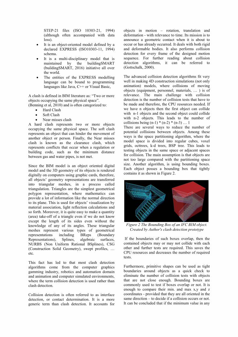
size. Another algorithm, is using bounding boxes.
Each object posses a bounding box that tightly
contains it as shown in Figure 2.
Figure 2 The Bounding Box of an IFC BIM object.
Created by Author's clash detection prototype
If the boundaries of such boxes overlap, then the
contained objects may or may not collide with each
other and further tests are required. This saves the
CPU resources and decreases the number of required
tests.
Furthermore, primitive shapes can be used as tight
boundaries around objects as a quick check to
eliminate the number of collision tests with objects
that are not close enough. Bounding boxes are
commonly used to test if boxes overlap or not. It is
enough to compare their min. and max x,y and z
coordinates - provided that they are all oriented in the
same direction – to decide if a collision occurs or not.
It can be concluded that if the minimum value in any
axis-direction (x, y or z) of one bounding box is
larger than the maximum values in the same direction
of the other bounding box that these two objects
cannot clash.
In the meantime, to refine the clash detection and
draw the intersection lines between two clashing
objects, it is enough to consider each triangle as a
plane (represented by three points) and each edge of
each triangle as a ray (vector). By iterating over each
triangle and each ray, it would be possible to find the
intersection points by using vector mathematics.
BIM and Clash Detection
A main advantage of BIM over other file exchange
formats is its ability not only to support the objects’
geometrical representations and topology, but also to
support the semantics of the building model’s
objects. For instance, a window is defined and
exchanged with its meaning and relationships to
other objects like walls and spaces. All of the
objects’ semantics and inter-relationships are defined
within the BIM schema. In this research, it is the
IFC-2X3 EXPRESS schema (IFC2X3, 2007). This
leads to the fact that the number of geometrical
collision detection tests can be limited to certain
semantically defined spaces or limited to a certain set
of objects with defined attributes or properties. For
example, a column and an HVAC duct in a certain
space (zone) on the third floor versus a pipe going
through a non-baring masonry wall. This enables the
categorization of clashes according to their impact on
the design. Moreover, it filters out a lot of irrelevant
clashes.
Therefore, an IFC BIM based clash / collision
detection should be able to:
Define semantically based BIM constraints
that can be used for filtering objects
undergoing the clash / collision detection
process. This should be based on the BIM
objects’ features (attributes and property
sets).
Map objects’ features to a database in a
simplified schema that enables standard
queries (e.g. SQL: Structured Query
Language) away from the complexity of the
IFC model definition with its complex
objectified relationship entities.
To have an interface for formulating queries
based on good knowledge of the IFC model
EXPRESS schema like EXPRESS-X (ISO
10303-14, 2005) or any of the programming
languages’ bindings to the schema.
To construct user defined “Auxiliary Query
Objects” that can be used as aiding tools in
constraining the query leading to a more
limited and defined set of potential BIM
objects. These auxiliary query objects can be
represented by virtual user defined
geometrical bounds such as bounding boxes,
bounding spheres, bounding polytopes or
bounding planes (half spaces) that can
represents spaces (volumes) bound between
construction axis or any other user defined
geometry. This enables the model to be
tested against an external set of constraints
other than those of the BIM internal object-
to-object clashes. It can test the entire model
against external rules and constraints such as
allowable foot print areas or built up
volumes, handicap constraint, emergency
exits, and minimum width of corridors or
doors … etc.
It is also worth emphasising that there is a broader
sense for checking a model other than object-to-
object simple geometrical clashes. An IFC BIM
model can be used for detecting the inconsistency or
lack of accuracy of the model. For example, the
bounding of walls to a certain space, the connection
between a beam and a column or a window that is
placed at a certain height above a slab, an object that
is placed above, blow, or beside another object,
where there is a need to test the above-mentioned
topological relations between objects in a BIM
model. However, the clash detection application must
allow for tolerance values. This is because the
floating-point precision used in the modelling of
objects goes beyond the metre and centimetre units
used for testing.
THE DEVELOPED PROTOTYPE
This paper introduces a JAVA based simple
prototype for clash detection that depends on
bounding boxes and spheres algorithm together with
a semantic mapping of objects’ attributes and
properties to a relational database (Microsoft Access
Database) to filter out objects that are not relevant for
clash detection.
Developed Tools
Due to the fact that IFC is defined in EXPRESS-
ISO10303-P11 (ISO 10303-11, 1994), and that it is a
modelling language and is not a programming
language, there was an inevitable need for binding
the EXPRESS schema to a programming language.
For the purpose of this prototype, a Java Toolbox –
that is created by the author - is used (Nour et al,
2008). It represents a Java early binding to the
IFC2X3 EXPRESS schema. It enables the parsing
and interpretation of IFC-STEP model files to
Runtime Java Objects with full access to its objects’
attributes. It enables the access to all kinds of
attributes including inverse attributes and optional
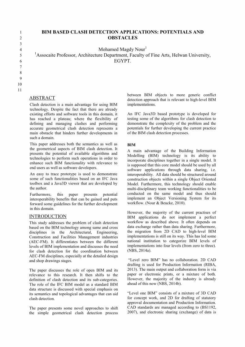
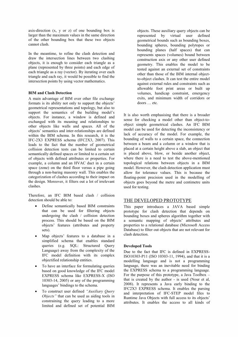
attributes. Furthermore, it constructs the IFC spatial
containment tree as shown in Figure 3.
Figure 3 Left: Spatial containment Tree,
Right: IFC3D viewer, Middle: IFC Model Navigator
Figure 4: An enlarged view of the IFC model
Navigator
It also allows the navigation through the model using
a graphical user interface, where all reference
attributes are navigated in the references graph
structure of the model as shown in Figure 3 and
Figure 4.
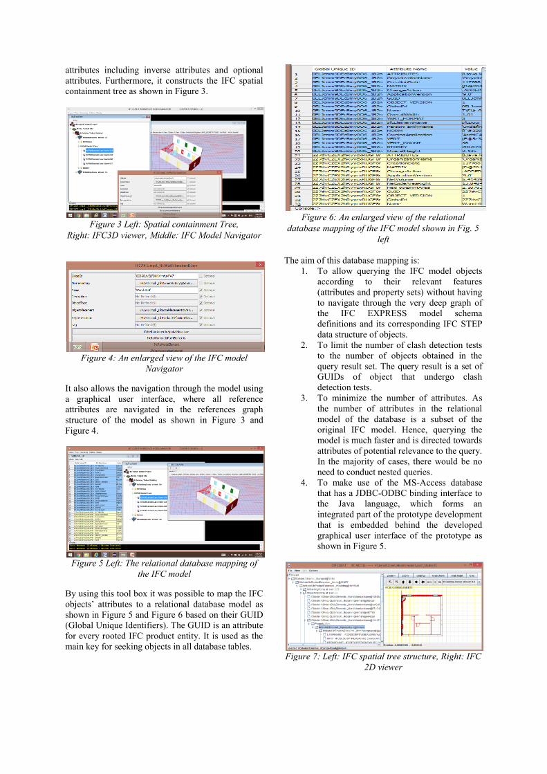
Figure 5 Left: The relational database mapping of
the IFC model
By using this tool box it was possible to map the IFC
objects’ attributes to a relational database model as
shown in Figure 5 and Figure 6 based on their GUID
(Global Unique Identifiers). The GUID is an attribute
for every rooted IFC product entity. It is used as the
main key for seeking objects in all database tables.
Figure 6: An enlarged view of the relational
database mapping of the IFC model shown in Fig. 5
left
The aim of this database mapping is:
1. To allow querying the IFC model objects
according to their relevant features
(attributes and property sets) without having
to navigate through the very deep graph of
the IFC EXPRESS model schema
definitions and its corresponding IFC STEP
data structure of objects.
2. To limit the number of clash detection tests
to the number of objects obtained in the
query result set. The query result is a set of
GUIDs of object that undergo clash
detection tests.
3. To minimize the number of attributes. As
the number of attributes in the relational
model of the database is a subset of the
original IFC model. Hence, querying the
model is much faster and is directed towards
attributes of potential relevance to the query.
In the majority of cases, there would be no
need to conduct nested queries.
4. To make use of the MS-Access database
that has a JDBC-ODBC binding interface to
the Java language, which forms an
integrated part of the prototype development
that is embedded behind the developed
graphical user interface of the prototype as
shown in Figure 5.
Figure 7: Left: IFC spatial tree structure, Right: IFC
2D viewer
To be able to conduct clash detection tests, there was
a need for a geometrical graphical representation of
the IFC model’s objects. Thus, a Java 2D/3D viewers
that were created by the author as shown in Figure 3,
Figure 5, Figure 7 and Figure 8. The Java 2D
graphical representation is of little relevance to this
study and the focus is therefore on the 3D
geometrical graphical representation.
Figure 8: The Java3D viewer of the IFC model
For the purpose of this study, the Java3D (ORACLE,
2016) is used together with the IFC Java tool box to
represent each IFC/BIM object (building element)
through a triangulated mesh. The Java3D platform
has the advantage of being an object oriented scene
graph –(directed acyclic graph) - based 3D API
(Application Programming Interface) for the Java
platform.
Due to the fact that the IFC EXPRESS schema
supports several geometrical representation types
like:
1. Geometric Set: IfcGeometricSet is used
for representing (2D or 3D) points,
curves, and/or surfaces, which do not
have a topological structure (such as
connected face sets or shells) and are not
solid models.
2. Surface Model: Any IfcBuildingElement
may be represented as a single or multiple
surface models, based on either shell or
face based models as shown in Figure 9.
Figure 9: The relation between the Surface model
and its bounding box. Source: (Liebich, 2009)
3. Solid Models: The majority of building
objects’ geometrical representation is
created as solid models. This includes
Swept Solids, Breps (Boudary
Representations), and CSG (Construction
Solid Geometry).
There has been an inevitable need to map the above
geometrical data structures to the Java3D data
structures as follows:
1- It had to be iterated over the interpreted
IFC model to search for objects that are
instances of the entity IfcProduct (A
tangible building object like walls, doors,
windows, etc.).
2- The IFC geometry of each object is
mapped to a Java3D object of class
GeomtryInfo, where a triangulation
process takes place. The mapping of the
surface models and Breps is a relatively
straightforward process, whereas the
creation of parametric (non evaluated)
Solid Models like CSG objects takes a
lot of effort.
3- IFC Solid models are created using
Java3D by sweeping, extrusion, and so
forth, once the extrusion or sweeping
directions are known. However, for
conducting Boolean operations for CSG
an external Java based Boolean Modeller
library (Balby, 2016) had to be used.
Once both the IFC java objects and their Java3D
geometrical representation are coupled together, it is
now possible to start detecting clashes. As a first
step, a semantic filtering takes place, where only the
instances (Objects) of the relevant classes are
included in the clash detection process. In addition, a
database SQL query can be executed using the
mapped relational model of the objects’ attributes
and property sets. This action limits further the
number of objects undergoing the clash detection
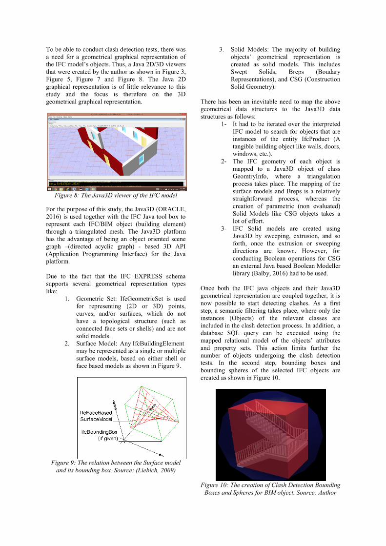
tests. In the second step, bounding boxes and
bounding spheres of the selected IFC objects are
created as shown in Figure 10.
Figure 10: The creation of Clash Detection Bounding
Boxes and Spheres for BIM object. Source: Author
Consequently, testing for a limited number of
overlapping (colliding) bounding boxes becomes an
easy task. Once a collision/clash is detected, then
classes of the Boolean Modeller library can be used
to define the intersection, difference or union of the
two objects as a newly introduced third object
represented as a Java3D Shape3D object. These three
objects are grouped together and identified as a clash
object group. This group is given a unique identifier
for further reference in the clash detection workflow
process, which is out of the scope of this paper.
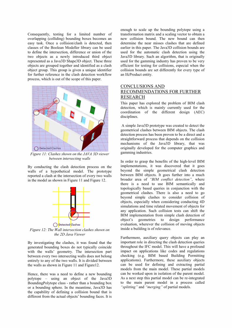
Figure 11: Clashes shown on the JAVA 3D viewer
between intersecting walls
By conducting the clash detection process on the
walls of a hypothetical model. The prototype
reported a clash at the intersection of every two walls
in the model as shown in Figure 11 and Figure 12.
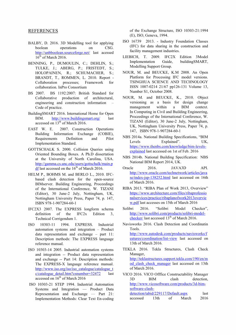
Figure 12: The Wall intersection clashes shown on
the 2D Java Viewer
By investigating the clashes, it was found that the
generated bounding boxes do not typically coincide
with the walls’ geometry. The intersection part
between every two intersecting walls does not belong
entirely to any of the two walls. It is divided between
the walls as shown in Figure 11 and Figure12.
Hence, there was a need to define a new bounding
polytope – using an object of the Java3D
BoundingPolytope class - rather than a bounding box
or a bounding sphere. In the meantime, Java3D has
the capability of defining a collision bound that is
different from the actual objects’ bounding faces. It is
enough to scale up the bounding polytope using a
transformation matrix and a scaling vector to obtain a
new collision bound. The new bound can then
determine the near misses clashes that are defined
earlier in this paper. The Java3D collision bounds are
used for the automatic clash detection using the
Java3D library. Such an algorithm, that is originally
used for the gamming industry has proven to be very
efficient for testing for collisions, especial when the
collision bounds are set differently for every type of
an IfcProduct entity.
CONCLUSIONS AND
RECOMMENDATIONS FOR FURTHER
RESEARCH
This paper has explored the problem of BIM clash
detection, which is mainly currently used for the
coordination of the different design (AEC)
disciplines.
A simple Java3D prototype was created to detect the
geometrical clashes between BIM objects. The clash
detection process has been proven to be a direct and a
straightforward process that depends on the collision
mechanisms of the Java3D library, that was
originally developed for the computer graphics and
gamming industries.
In order to grasp the benefits of the high-level BIM
implementations, it was discovered that it goes
beyond the simple geometrical clash detection
between BIM objects. It goes further into a much
broader area of “BIM conflict detection”, where
there is a need to use BIM semantically and
topologically based queries in conjunction with the
geometrical clashes. There is also a need to go
beyond simple clashes to consider collision of
objects, especially when considering conducting 4D
simulations and time related movement of objects for
any application. Such collision tests can shift the
BIM implementation from simple clash detection of
object’s geometries to design performance
evaluation, wherever the collision of moving objects
inside a building is of relevance.
Furthermore, auxiliary query objects can play an
important role in directing the clash detection queries
throughout the IFC model. This will have a profound
impact on applications like codes and regulations
checking (e.g. BIM based Building Permitting
applications). Furthermore, these auxiliary objects
can be used for defining and extracting partial
models from the main model. These partial models
can be worked upon in isolation of the parent model.
As a next step this partial model can be re-integrated
to the main parent model in a process called
“splitting” and “merging” of partial models.
REFERENCES
BALBY, D. 2016. 3D Modelling tool for applying
boolean operations on CSG.
http://unbboolean.sourceforge.net/ last acessed
16th
of March 2016.
BENNING, P., DUMOULIN, C.; DEHLIN, S.;
TULKE, J.; ABERG, P.; FRISTEDT, S.;
HOLOPAINEN, R.; SCHUMACHER, S.;
BRANDT, T., ROMMEN, L. 2010. Report -
Collaboration processes; Framework for
collaboration. InPro Consortium
BS 2007. BS 1192:2007: British Standard for
Collaborative production of architectural,
engineering and construction information –
Code of practice.
BuildingSMART 2016. International Home for Open
BIM. http://www.buildingsmart.org/ last
accessed on 13th
of March 2016.
EAST W. E. 2007. Construction Operations
Building Information Exchange (COBIE),
Requirements Definition and Pilot
Implementation Standard.
GOTTSCHALK S. 2000. Collision Queries using
Oriented Bounding Boxes. A Ph.D dissertation
at the University of North Carolina, USA.
http://gamma.cs.unc.edu/users/gottschalk/main.p
df last accessed on the 16th
of March 2016.
HELM P., BOHMS M. and BERLO L., 2010. IFC-
based clash detection for the open-source
BIMserver. Building Engineering, Proceedings
of the International Conference, W. TIZANI
(Editor), 30 June-2 July, Nottingham, UK,
Nottingham University Press, Paper 74, p. 147,
ISBN 978-1-907284-60-1
IFC2X3 2007. The EXPRESS longform schema
definition of the IFC2x Edition 3,
Technical Corrigendum 1.
ISO 10303-11 1994. EXPRESS. Industrial
automation systems and integration – Product
data representation and exchange – part 11:
Description methods: The EXPRESS language
reference manual.
ISO 10303-14 2005. Industrial automation systems
and integration -- Product data representation
and exchange -- Part 14: Description methods:
The EXPRESS-X language reference manual.
http://www.iso.org/iso/iso_catalogue/catalogue_t
c/catalogue_detail.htm?csnumber=32472 last
accessed on 16th
of March 2016
ISO 10303-21 STEP 1994. Industrial Automation
Systems and Integration — Product Data
Representation and Exchange — Part 21:
Implementation Methods: Clear Text En-coding
of the Exchange Structure, ISO 10303-21:1994
(E), ISO, Geneva, 1994.
ISO 16739 2013. - Industry Foundation Classes
(IFC) for data sharing in the construction and
facility management industries.
LIEBICH, T. 2009. IFC2X Edition 3Model
Implementation Guide, buildingSMART,
Modelling Support Group.
NOUR, M. and BEUCKE, K.M 2008. An Open
Platform for Processing IFC model versions.
TSINGHUA SCIENCE AND TECHNOLOGY
ISSN 1007-0214 21/67 pp126-131 Volume 13,
Number S1, October 2008.
NOUR, M. and BEUCKE, K., 2010. Object
versioning as a basis for design change
management within a BIM context.
In Computing in Civil and Building Engineering,
Proceedings of the International Conference, W.
TIZANI (Editor), 30 June-2 July, Nottingham,
UK, Nottingham University Press, Paper 74, p.
147, ISBN 978-1-907284-60-1
NBS 2014a. National Building Specifications, “BIM
Levels Explained”. UK,
https://www.thenbs.com/knowledge/bim-levels-
explained last accessed on 1st of Feb. 2016
NBS 2014b. National Building Specification: NBS
National BIM Report 2014, UK.
Oracle 2016. JAVA3D API.
http://www.oracle.com/technetwork/articles/java
se/index-jsp-138252.html last accessed on 16th
of March 2016.
RIBA 2013. “RIBA Plan of Work 2013, Overview”
https://www.architecture.com/files/ribaprofessio
nalservices/practice/ribaplanofwork2013overvie
w.pdf last accesses on 15th of March 2016
Solibri 2016. “Solibri Model Checker”,
http://www.solibri.com/products/solibri-model-
checker/ last accessed 13th
of March 2016.
Navisworks 2016. Clash Detection and Coordinatin
Tools.
http://www.autodesk.com/products/navisworks/f
eatures/coordination/list-view last accessed on
13th of March 2016.
TEKLA 2016. Tekla Structures, Clash Check
Manager,
http://teklastructures.support.tekla.com/190/en/m
od_clash_check_manager last accessed on 13th
of March 2016.
VICO 2016. VICO Offfice Constructability Manager
3D BIM clash detection,
http://www.vicosoftware.com/products/3d-bim-
software-clash-
detection/tabid/229117/Default.aspx last
accessed 13th of March 2016