Embed Size (px)
Citation preview

Part No 351502 Form No F030311A
1
OS900SP Owner’s Manual
Unit shown with Seed Box Lid, sold separately
BILLY GOAT SELF PROPELLED OVERSEEDER
OS900SPS, OS900SPH
Owner's Manual Accessories Replacement Parts
Seed Box Lid Kit Chariot Kit Reel Kit
A convenient way to enclose the seed box
P/N 351600
Allows the user to ride behind the unit and decrease fatigue
from walking
P/N 351601
Use to replace worn or damaged reels
P/N 351603
Part No 351502 Form No F030311A 2
OS900SP Owner’s Manual
ABOUT THIS MANUAL THANK YOU for purchasing a BILLY GOAT
® Self-propelled Overseeder. Your new machine has been carefully
designed and manufactured to provide years of reliable and productive service. This manual provides complete operating and maintenance instructions that will help to maintain your machine in top running order. Read this manual carefully before assembling, operating, or servicing your equipment.
CONTENTS
SERIAL PLATE DATA AND SPECIFICATIONS 3 GENERAL SAFETY 4 -5 SOUND AND VIBRATION 6 INSTRUCTION LABELS 7 PACKING CHECKLIST & ASSEMBLY 8 OPERATION 9-12 MAINTENANCE 13 TROUBLESHOOTING AND WARRANTY PROCEDURE 14 PARTS LIST____________ 15-25 MAINTENANCE RECORD 26

Part No 351502 Form No F030311A
3
OS900SP Owner’s Manual
SERIAL PLATE DATA
Record the model number, serial number, date of purchase, and where purchased.
Purchase Date:
Purchased From:
Specifications OS900SPS OS900SPH
Engine: HP’ 9.0 HP (6.7kW) 9.0 HP (6.7kW)
Engine: Model EX270DE5032 GX270K1QA2
Engine: Type Subaru Honda
Engine: Fuel Capacity 6.4 qt. (6.1 L) 5.6 qt. (5.3 L)
Engine: Oil Capacity 1.06 qt. (1 L) 1.16 qt. (1.1 L)
Total Unit Weight: 314# (142 kg) 323# (147 kg)
Max. operating slope 15o 20
o
Sound test in accordance with 2000/14/EC 104 dB(a) 104 dB(a)
Sound at operators ear 84 dB(a) 84 dB(a)
Vibration at operator position 0.81g (7.95 m/s2) 0.81g (7.95 m/s
2)
Part No 351502 Form No F030311A 4
OS900SP Owner’s Manual
GENERAL SAFETY INSTRUCTIONS and SYMBOLS
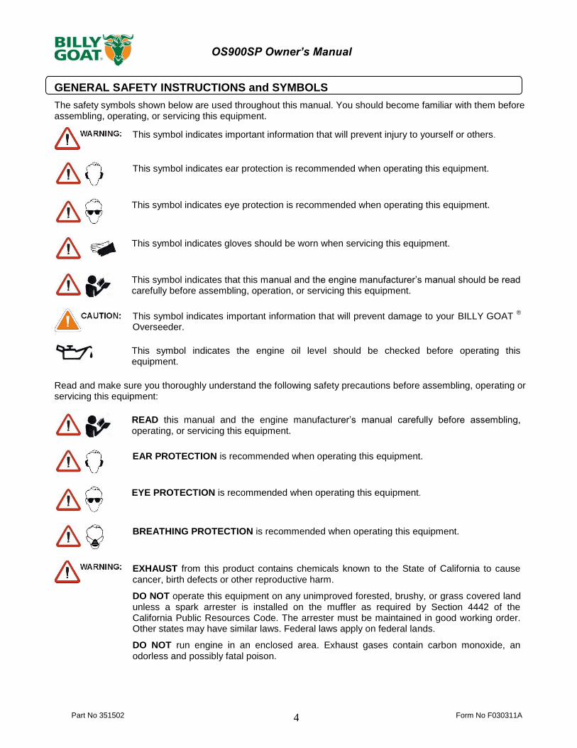
The safety symbols shown below are used throughout this manual. You should become familiar with them before assembling, operating, or servicing this equipment.
This symbol indicates important information that will prevent injury to yourself or others.
This symbol indicates ear protection is recommended when operating this equipment.
This symbol indicates eye protection is recommended when operating this equipment.
This symbol indicates gloves should be worn when servicing this equipment.
This symbol indicates that this manual and the engine manufacturer’s manual should be read carefully before assembling, operation, or servicing this equipment.
This symbol indicates important information that will prevent damage to your BILLY GOAT ®
Overseeder.
This symbol indicates the engine oil level should be checked before operating this equipment.
Read and make sure you thoroughly understand the following safety precautions before assembling, operating or servicing this equipment:
READ this manual and the engine manufacturer’s manual carefully before assembling, operating, or servicing this equipment.
EAR PROTECTION is recommended when operating this equipment.
EYE PROTECTION is recommended when operating this equipment.
BREATHING PROTECTION is recommended when operating this equipment.
EXHAUST from this product contains chemicals known to the State of California to cause cancer, birth defects or other reproductive harm.
DO NOT operate this equipment on any unimproved forested, brushy, or grass covered land unless a spark arrester is installed on the muffler as required by Section 4442 of the California Public Resources Code. The arrester must be maintained in good working order. Other states may have similar laws. Federal laws apply on federal lands.
DO NOT run engine in an enclosed area. Exhaust gases contain carbon monoxide, an odorless and possibly fatal poison.

Part No 351502 Form No F030311A
5
OS900SP Owner’s Manual
DO NOT run this equipment indoors or in any poorly ventilated area. Refueling outdoors is recommended.
DO NOT refuel this equipment while the engine is running. Allow engine to cool for at least two minutes before refueling.
DO NOT store gasoline near an open flame.
DO NOT remove gas cap while engine is running.
DO NOT start or operate engine if strong odor of gasoline is present.
DO NOT start or operate engine if gasoline is spilled. Move equipment away from spill until gasoline has completely evaporated.
DO NOT smoke while filling the fuel tank.
DO NOT check for spark with spark plug or spark plug wire removed. Use an approved spark tester.
DO NOT operate engine without a muffler. Inspect muffler periodically and replace if necessary. If equipped with muffler deflector, inspect deflector periodically and replace if necessary.
DO NOT operate engine with grass, leaves or other combustible material near the muffler.
DO NOT touch muffler, cylinder, or cooling fins when hot. Contact with hot surfaces may cause severe burns.
DO NOT leave equipment unattended while in operation.
DO NOT park equipment on a steep grade or slope.
DO NOT operate equipment with bystanders in or near the work area.
DO NOT allow children to operate this equipment.
DO NOT operate equipment without guards in place.
DO NOT operate equipment near hot or burning debris or any toxic or explosive materials.
DO NOT operate equipment on slopes greater than specified in Specifications section of this manual.
DO NOT start engine without height adjust lever in up position and clutch bail disengaged.
DO NOT place hands or feet underneath unit, or near any moving parts.
ALWAYS remove spark plug wire when servicing equipment to prevent accidental starting.
ALWAYS check fuel lines and fittings frequently for cracks or leaks. Replace if necessary.
ALWAYS keep hands and feet away from moving or rotating parts.
ALWAYS store fuel in approved safety containers.
WARNING: Important
Remove all rocks, wire, string, etc. that can present a hazard during work prior to starting.
DO identify and mark all fixed objects to be avoided during work such as sprinkler heads, water valves, buried cables, or clothes line anchors, etc.
Part No 351502 Form No F030311A 6
OS900SP Owner’s Manual
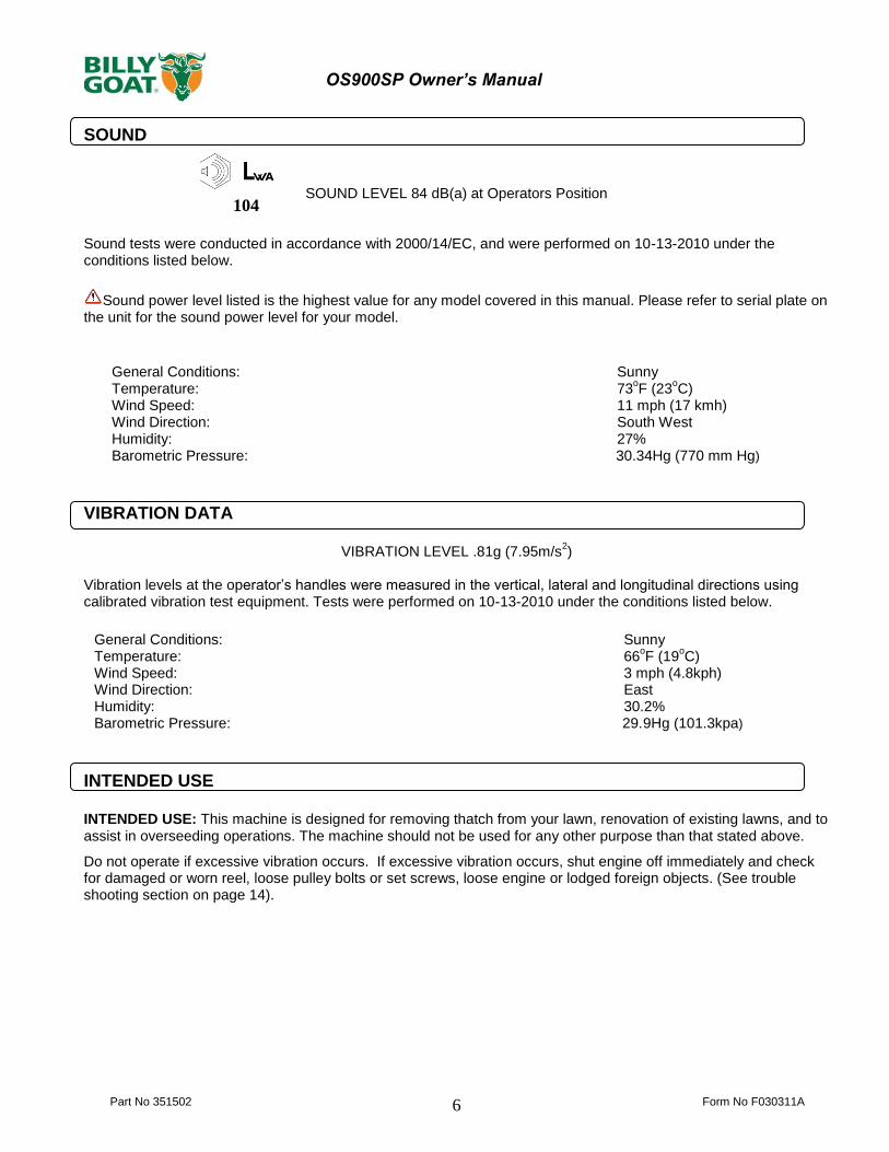
SOUND
SOUND LEVEL 84 dB(a) at Operators Position
Sound tests were conducted in accordance with 2000/14/EC, and were performed on 10-13-2010 under the conditions listed below.
Sound power level listed is the highest value for any model covered in this manual. Please refer to serial plate on the unit for the sound power level for your model.
VIBRATION DATA
VIBRATION LEVEL .81g (7.95m/s2)
Vibration levels at the operator’s handles were measured in the vertical, lateral and longitudinal directions using calibrated vibration test equipment. Tests were performed on 10-13-2010 under the conditions listed below.
INTENDED USE INTENDED USE: This machine is designed for removing thatch from your lawn, renovation of existing lawns, and to assist in overseeding operations. The machine should not be used for any other purpose than that stated above.
Do not operate if excessive vibration occurs. If excessive vibration occurs, shut engine off immediately and check for damaged or worn reel, loose pulley bolts or set screws, loose engine or lodged foreign objects. (See trouble shooting section on page 14).
General Conditions: Sunny Temperature: 73
oF (23
oC)
Wind Speed: 11 mph (17 kmh) Wind Direction: South West Humidity: 27% Barometric Pressure: 30.34Hg (770 mm Hg)
General Conditions: Sunny Temperature: 66
oF (19
oC)
Wind Speed: 3 mph (4.8kph) Wind Direction: East Humidity: 30.2% Barometric Pressure: 29.9Hg (101.3kpa)
104

Part No 351502 Form No F030311A
7
OS900SP Owner’s Manual
INSTRUCTION LABELS
The labels shown below were installed on your BILLY GOAT
® Overseeder. If any labels are damaged or missing, replace them before operating
this equipment. Item numbers from the Illustrated Parts List and part numbers are provided for convenience in ordering replacement labels. The correct position for each label may be determined by referring to the Figure and Item numbers shown.
LABEL DANGER KEEP HANDS LABEL CLUTCH ITEM #142 LABEL TRANS. RELEASE AND FEET AWAY P/N 500177 ITEM #146 P/N 351507 ITEM #145 P/N 400424
LABEL CAUTION GUARDS LABEL DEPTH GAUGE ITEM #133 P/N 900327 ITEM #59 P/N 351504
LABEL INSTRUCTIONS SEEDER BOX LABEL SEED METERING ITEM #56 P/N 351501 ITEM #66 P/N 351503 (page 12) (page 12)
ENGINE LABELS
.
SUBARU HONDA

Part No 351502 Form No F030311A 8
OS900SP Owner’s Manual
PACKING CHECKLIST Your Billy Goat Overseeder is shipped from the factory in one carton, completely assembled.
PUT OIL IN ENGINE BEFORE STARTING
ASSEMBLY
READ all safety instructions before assembling unit. TAKE CAUTION when removing the unit from the box the Handle Assembly is attached to the unit and cables could snag.
1. UNFOLD the upper handle and slide handle lock loops (item 35) into place to secure the upper handle to the lower. 2. CHECK engine oil level and fill to proper level with engine manufacturers recommended grade of oil. Move height adjust lever to down position, to level engine during checking. See engine manufacturers’ instruction manual.
3. CONNECT spark plug wire.
Boxing Parts Checklist
Subaru 9 HP
Honda 9 OHV
Parts bag P/N-351009
PARTS BAG & LITERATURE ASSY
Warranty card P/N- 400972, Owner’s Manual P/N-351502, Declaration of Conformity P/N-351508.

Part No 351502 Form No F030311A
9
OS900SP Owner’s Manual
OPERATION
Like all mechanical tools, reasonable care must be used when operating machine. Inspect machine work area and machine before operating. Make sure that all operators of this equipment are trained in general machine use and safety.
PUT OIL IN ENGINE BEFORE STARTING STARTING
ENGINE: See engine manufacturer’s instructions for type and amount of oil and gasoline used. Engine must be level when checking and filling oil and gasoline. FUEL VALVE: Move fuel valve to "ON" position (when provided on engine). STOP SWITCH: Located on the engine. "ON" position. CHOKE: Operated with choke lever on side of engine. THROTTLE: Controlled by throttle lever on the motor. Forward/Reverse: The controls are found on the underside of the upper handle. Forward motion will be controlled with the right hand lower lever and Reverse will be controlled with the left hand lower lever. DO NOT tie down the control levers for use. IF YOUR UNIT FAILS TO START: See Troubleshooting on page 14.
HANDLING & TRANSPORTING:
This unit requires two people to lift it. With the handle in the folded position, lift holding the lower handle and
front wheel one on each side of the machine. Secure the machine in place during transport. See page 3 for weight specifications
Never lift the machine while the engine is running.
ADJUSTING BLADE DEPTH
The depth of the blades can be raised or lowered by rotating the knob located at the rear of the machine. The relative depth of the blades can be gauged by using the depth scale located on the rear of the machine and the bar next to it.
FOLDING HANDLE
This unit is equipped with a folding upper handle for easier storage and transportation. The handle can be folded by sliding the handle lock loops (item 35) up. This releases the upper handle, allowing it to be folded over the unit.
BLADE POSITION & DEPTH CONTROL LEVER
The blades can be raised or lowered into the ground by height adjustment lever at the rear of the unit. The blades will be in their lowered position when the lever is to the left and should be locked in the notch on the right when in transport. The resulting blade depth can be adjusted higher or lower. See ADJUSTING BLADE DEPTH above.

Part No 351502 Form No F030311A 10
OS900SP Owner’s Manual
SLICING TIPS
Before beginning, it is best to evaluate the condition of the lawn by cutting one or more core samples from area to be treated. A core can be cut using a piece of pvc, or metal pipe. Hammer the pipe into the ground, remove it, push the core out of the pipe and inspect it to determine the depth of thatch in your yard. THATCH: Thatch is a dense layer of dead grass, clippings, and roots that builds up over time
at the base of the lawn preventing air, water, and fertilizer from reaching the soil. This can cause shallow root development and make a lawn more susceptible to drought and disease. Thatch also provides an ideal environment for insects to hide and multiply. Periodic removal of thatch will keep your lawn in good health. HEAVY THATCH: Lawns with an excessive amount of thatch will require multiple treatments
for effective removal. Trying to remove excessive thatch (greater than 3/4"[19 mm] deep) in one treatment will damage or destroy the living part of the lawn. It is best to remove heavy thatch in seasonal treatments (i.e. spring, and fall). SLOPES: Rake slopes across not up and down. This is much easier and safer for the operator
and is better for the lawn. Raking across will help to reduce runoff during watering and allow the sloped ground to hold more seed, fertilizer, and water. The unit’s maximum operating slope is 35% or 19°. DEPTH: The wide range of depth adjustment on your unit is provided to allow for blade wear.
Setting the reel deeper will not produce better, or quicker results. The slicing reel should be set even with the ground for verti-slicing work, and set to a maximum 1/2" depth for overseeding jobs. Setting the reel deeper than this will only result in premature wear on the unit (i.e. failed belt). If you desire to work the ground deeper than the above guidelines allow, it should be done gradually in multiple passes.. VERTICUTTING / OVERSEEDING: Mow the lawn to shorter than the normal cut height before
starting (i.e. approximately 2" tall for fescue grass). For the best result, Slice/Overseed in criss- cross pattern (See Fig. 1 and See Fig 2).
Fig. 1
Fig. 2
VERTI-CUTTING OPERATION
MOW: Mow the lawn to shorter than the normal cut height (approximately 2" tall) DRY: Be sure grass is dry. Wet conditions can cause increased damage to healthy grass. SET DEPTH: With engine off, set the raking depth so that the blades just touch on a flat surface
(i.e. driveway, or sidewalk). START ENGINE: See Page 9. ENGAGE BLADES: Push the Reel Lever down on the operators handle (upper left side).
NOTE: When engaging the blades in heavy load conditions (i.e. heavy thatch, or very uneven turf), push down on the operators handle lifting the front wheels slightly. Engage the blades. Slowly lower the unit into the turf. SLICE: Verti-cut a small test area and examine the results. Some thatch and cut stems should
be removed and deposited on top of the healthy grass. Grass runners should be cut and ready for removal. If excessive damage occurs to healthy grass, adjust the blade depth to decrease damage. Continue raking the yard, working in one direction (i.e. north-south, or east-west). NOTE: If a large drop in engine RPM occurs, or bounces during operation the blade depth is set too low. REMOVE THATCH/STEMS: After verti-cutting, a layer of thatch and cut stems will be deposited
over the top of the lawn. We suggest the use of a lawn vacuum or wheeled blower for collection and removal of the thatch/stems.

Part No 351502 Form No F030311A
11
OS900SP Owner’s Manual
OVERSEEDING OPERATION MOW: Mow the lawn to shorter than the normal cut height (approximately 2" tall) DRY: Be sure grass is dry. Wet conditions can cause increased damage to healthy grass.
SEED: Spread grass seed according to the seed suppliers directions (e.g. 10 lbs. per 1000 ft2 [4.5
kg. per 93 m2 ]) Adjustments to the seed drop is located on the front of the unit on the seed dial and should be used in conjunction with the seed chart on the console. SET DEPTH: With engine off, set the raking depth so that the blades reach 1/4"-1/2"(6-12 mm)
below a flat surface (i.e. driveway, or sidewalk). START ENGINE: See Page 9. ENGAGE REEL AND SEED DROP: Push down on the Reel lever on the operators handle. NOTE: When engaging the reel in heavy load conditions (i.e. heavy thatch, or very uneven turf), push down on the operators handle lifting the front wheels slightly. Engage the reel. Slowly lower the unit into the turf. SLICE: Run machine over the area that has been seeded to incorporate the seed into the soil. If
excessive damage occurs to healthy grass, adjust the blade depth to decrease damage. Continue raking the yard, working in one direction (i.e. north-south, or east-west). NOTE: If a large drop in engine RPM occurs, or bounces during operation the blade depth is set too low. WATER/FERTILIZE: After the seed has been worked into the soil, water and fertilize according to
the seed suppliers directions.
Part No 351502 Form No F030311A 12
OS900SP Owner’s Manual
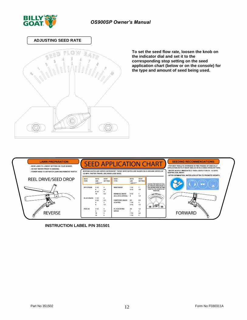
ADJUSTING SEED RATE
INSTRUCTION LABEL P/N 351501
To set the seed flow rate, loosen the knob on the indicator dial and set it to the corresponding stop setting on the seed application chart (below or on the console) for the type and amount of seed being used.

Part No 351502 Form No F030311A
13
OS900SP Owner’s Manual
MAINTENANCE PERIODIC MAINTENANCE
Periodic maintenance should be performed at the following intervals:
Maintenance Operation Every Use (daily) Every 25 Hours
Inspect for loose, worn or damaged parts.
Check engine oil
Inspect belts
Engine (See Engine Manual)
Grease bearings
Inspect and clean engine air filter
Oil height adjustment linkage
SLICING BLADE WEAR 1. Wait for engine to cool and disconnect spark plug. 2. Close fuel valve on engine (if available). 3. Lean unit back onto lower handles and secure in place. 4. Inspect blades for wear, and immediately replace any deformed or cracked blades. Measure the overall diameter of the blade. 5. If blades are warped or the diameter of the blade is 6.75"(171 mm) in length they must be
replaced. NOTE: We recommend replacing all the blades at once.
JACKSHAFT BELT REPLACEMENT 1. Wait for engine to cool and disconnect spark plug. 2. Place the rear of the unit on blocks. 3. Remove the right rear tire (item 11) and spring (item 155) attaching the housing to the frame. 4. Remove (3) screws (item 114) holding the belt guard (item 19) in place 5. Remove the four screws (item 107) holding the mule drive assembly (item 60) in place. 6. Remove the belt (item 14) by rotating the mule drive pulley and walking it out of the groove, and remove the mule assembly leaving the belt on the transmission. 7. Remove the carriage bolt and nuts holding the right bearing on the jackshaft. Do not remove the bearing and pulley. 8. Remove the belt guard (item 58) by removing the three screws (item 114). 9. Walk the belt off of the crankshaft pulley, and then slide it down the jackshaft to the bearing hole. This will allow the belt to be slid around the mule pulley. 10. Replace the belt by feeding it into the hole and around the pulley that the old one was removed. Make sure it is seated in the jackshaft pulley and then walk it onto the crankshaft pulley making sure it is inside the belt fingers. 11. Reattach the bearing and tighten the hardware securely. 12. Reattach the mule drive and belt, making sure that the belt is seated properly in the transmission pulley and the mule drive assembly. 13. Check the idler tension on the belt when the drive lever is engaged, if it is too loose the spring (item 82) holding the idler arm will need to be replaced. 14. Reattach the guards, tire, spring and spark plug and make sure of proper operation.
REEL BELT REPLACEMENT 1. Wait for engine to cool and disconnect spark plug. 2. Remove (2) screws (item 38) holding the belt guard (item 20) in place 3. Remove the belt (item 17) by rotating the reel pulley (item16) and walking it out of the groove. Discard old belt. 4. Install new belt using same procedure to walk the belt into the groove, making sure that it is inside the belt fingers. 5. With new belt installed push the reel drive lever down and make sure the idler pulley puts tension on the cable. The proper adjustment should have the blade lever fully engaged and the belt should be snug on the pulleys. 6. Re-install the belt guard and reattach the spark plug.
MULE BELT REPLACEMENT 1. Wait for engine to cool and disconnect spark plug. 2. Place the rear of the unit on blocks. 3. Remove the right rear tire (item 11) and spring (item 155) attaching the housing to the frame. 4. Remove (3) screws (item 114) holding the belt guard (item 19) in place 5. Remove the four screws (item 107) holding the mule drive assembly (item 60) in place. This will allow access to the belt. 6. Remove the belt (item 14) by rotating the mule drive pulley and walking it out of the groove, and then sliding it off of the transmission. Discard old belt. 7. Install new belt using same procedure to walk the belt into the groove, making sure it is seated fully in all pulleys. Reattach the mule drive assembly. 8. With new belt installed pull the drive levers up and make sure the idler pulley puts tension on the cable. The proper adjustment should have the drive lever fully engaged and the belt should be snug on the pulleys. 9. Re-install the belt guard, spring, and tire, then reattach the spark plug.

Part No 351502 Form No F030311A 14
OS900SP Owner’s Manual
STORAGE
Never store engine indoors or in enclosed poorly ventilated areas with fuel in tank, where fuel fumes may reach an open flame, spark or pilot light, as on a furnace, water heater, clothes dryer or other gas appliance. If engine is to be unused for 30 days or more, prepare as follows:
Remove all gasoline from carburetor and fuel tank to prevent gum deposits from forming on these parts and causing possible malfunction of engine. Drain fuel outdoors, into an approved container, away from open flame. Be sure engine is cool. Do not smoke. Run engine until fuel tank is empty and engine runs out of gasoline.
Troubleshooting
When servicing engine refer to specific manufacturers’ engine owner's manual. Engine warranty is covered by the specific engine manufacturer. If your engine requires warranty or other repair work, contact your local servicing engine dealer. When contacting a dealer for service it is a good idea to have your engine model number available for reference (See table page 3). If you cannot locate a servicing dealer in your area you can contact the manufacturers’ national service organization. To reach:
American Honda: 800-426-7701 Subaru America: 800-277-6246 WARRANTY CLAIM PROCEDURE Should a BILLY GOAT
® machine fail due to a defect in material and/or workmanship, the owner should make a warranty claim
as follows:
The machine must be taken to the dealer from whom it was purchased or to an authorized Servicing BILLY GOAT Dealer.
The owner must present the remaining half of the Warranty Registration Card, or, if this is not available, the invoice or receipt.
The Warranty Claim will be completed by the authorized BILLY GOAT Dealer and submitted to their respective BILLY GOAT Distributor for their territory Attention: Service Manager. Any parts replaced under warranty must be tagged and retained for 90 days. The model number and serial number of the unit must be stated in the Warranty Claim.
The distributor service manager will sign off on the claim and submit it to BILLY GOAT for consideration.
The Technical Service Department at BILLY GOAT will study the claim and may request parts to be returned for examination. BILLY GOAT will notify their conclusions to the distributor service manager from whom the claim was received.
The decision by the Technical Service Department at BILLY GOAT to approve or reject a Warranty Claim is final and binding.
For online product registration go to www.billygoat.com
Problem Possible Cause Solution
Abnormal vibration. · Damaged or missing blades. Loose
handle bolts. Loose engine bolts
· Stop work immediately. Replace any
damaged or missing blades. Tighten all
loose nuts and bolts.
Engine stalls or labors when
raking
· Blades set too deep into ground. · Raise blades so that they just touch the
ground on a level surface
Engine will not start. · Stop switch off (Honda only). Throttle
in off position
· Check choke position.
· Out of gasoline or bad, old gasoline. · Check gasoline.
· Spark Plug wire disconnected. · Connect spark plug wire.
· Gas valve off. · Turn on gas valve.
· Dirty air cleaner. · Clean or replace air cleaner. Contact a
qualified service person.
Engine is locked, will not pull
over.
· Debris locked against reel, or drive
pulleys. Engine problem.
· Pull spark plug wire and remove debris.
Contact an engine servicing dealer for
engine problems.

Part No 351502 Form No F030311A
15
OS900SP Owner’s Manual
SLICING REEL ASSY 351603
PARTS DRAWING
6
5
43
2
1
ITEM NO DESCRIPTION PART NO. QTY
1 SHAFT VERTICUTTING REEL OS900SP 351111 1
2 BLADE VERTICUT OS900SP 351225 11
3 SPACER PM REEL OS900SP 351261 10
4 SPACER HARDENED REEL OS900SP 351297 1
5 SPRING DISC 7/8" ID 351298 1
6 NUT 7/8"-14 NC 350341 1
Part No 351502 Form No F030311A 16
OS900SP Owner’s Manual
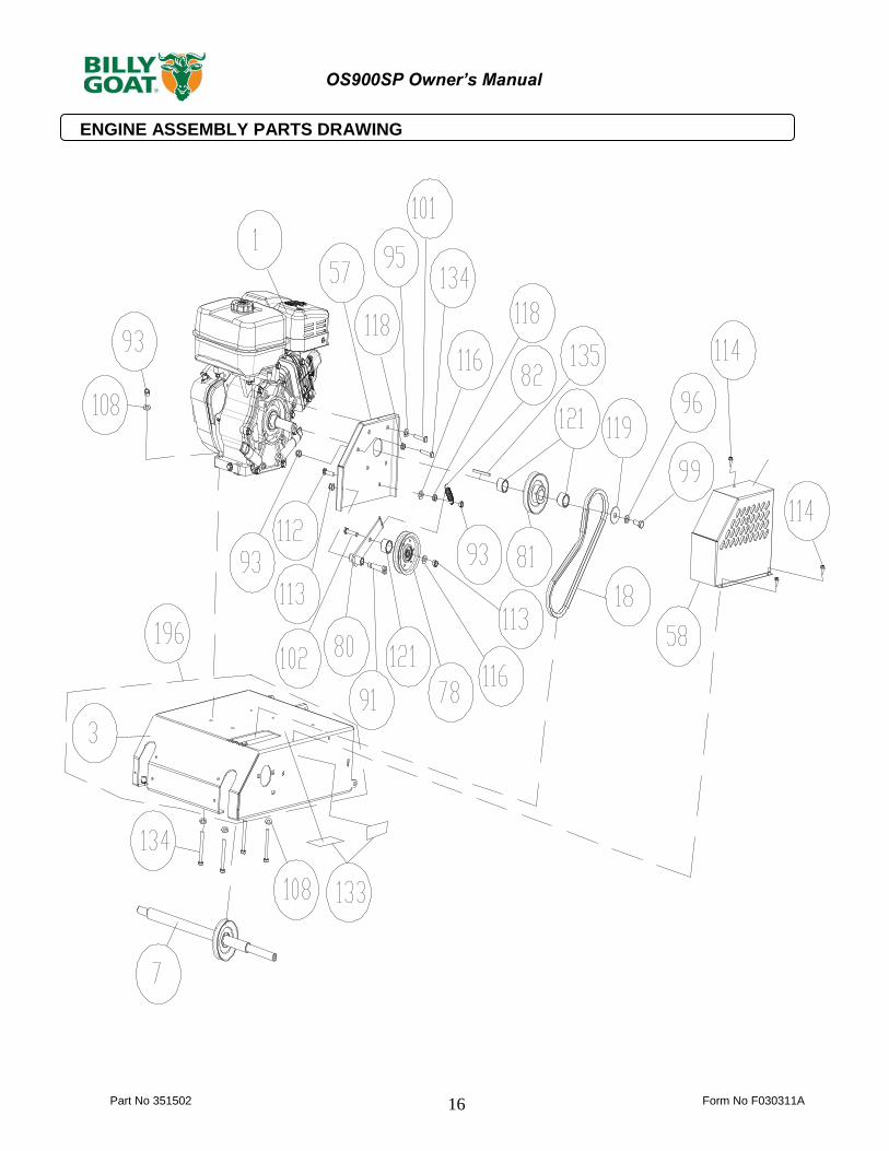
ENGINE ASSEMBLY PARTS DRAWING
Part No 351502 Form No F030311A
17
OS900SP Owner’s Manual
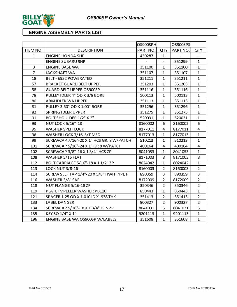
ENGINE ASSEMBLY PARTS LIST
OS900SPH OS900SPS
ITEM NO. DESCRIPTION PART NO. QTY PART NO. QTY
1 ENGINE HONDA 9HP 430287 1 - -
ENGINE SUBARU 9HP - - 351299 1
3 ENGINE BASE WA 351100 1 351100 1
7 JACKSHAFT WA 351107 1 351107 1
18 BELT - 6932 POWERATED 351211 1 351211 1
57 BRACKET GUARD BELT UPPER 351203 1 351203 1
58 GUARD BELT UPPER OS900SP 351116 1 351116 1
78 PULLEY IDLER 4" OD X 3/8 BORE 500113 1 500113 1
80 ARM IDLER WA UPPER 351113 1 351113 1
81 PULLEY 3.50" OD X 1.00" BORE 351296 1 351296 1
82 SPRING IDLER UPPER 351275 1 351275 1
91 BOLT SHOULDER 1/2" X 2" 520031 1 520031 1
93 NUT LOCK 5/16"-18 8160002 6 8160002 6
95 WASHER SPLIT LOCK 8177011 4 8177011 4
96 WASHER LOCK 7/16' S/T MED 8177013 1 8177013 1
99 SCREWCAP 7/16"-20 X 1" HCS GR. 8 W/PATCH 510213 1 510213 1
101 SCREWCAP 5/16"-24 X 1" GR 8 W/PATCH 400164 4 400164 4
102 SCREWCAP 3/8"-16 X 1 3/4" HCS ZP 8041053 1 8041053 1
108 WASHER 5/16 FLAT 8171003 8 8171003 8
112 BOLT CARRIAGE 5/16"-18 X 1 1/2" ZP 8024042 1 8024042 1
113 LOCK NUT 3/8-16 8160003 2 8160003 2
114 SCREW SELF TAP 1/4"-20 X 5/8" HWH TYPE F 890359 3 890359 3
116 WASHER 3/8" SAE 8172009 2 8172009 2
118 NUT FLANGE 5/16-18 ZP 350346 2 350346 2
119 PLATE IMPELLER WASHER PB110 850443 1 850443 1
121 SPACER 1.25 OD X 1.010 ID X .938 THK 351413 2 351413 2
133 LABEL DANGER 900327 2 900327 2
134 SCREWCAP 5/16"-18 X 1 3/4" HCS ZP 8041031 5 8041031 5
135 KEY SQ 1/4" X 1" 9201113 1 9201113 1
196 ENGINE BASE WA OS900SP W/LABELS 351608 1 351608 1
Part No 351502 Form No F030311A 18
OS900SP Owner’s Manual
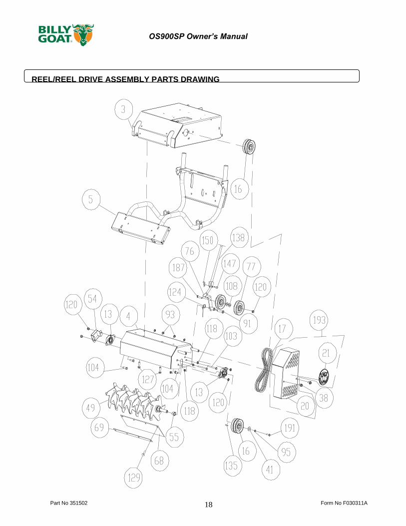
REEL/REEL DRIVE ASSEMBLY PARTS DRAWING
Part No 351502 Form No F030311A
19
OS900SP Owner’s Manual
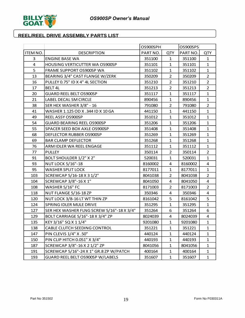
REEL/REEL DRIVE ASSEMBLY PARTS LIST
OS900SPH OS900SPS
ITEM NO. DESCRIPTION PART NO. QTY PART NO. QTY
3 ENGINE BASE WA 351100 1 351100 1
4 HOUSING VERTICUTTER WA OS900SP 351101 1 351101 1
5 FRAME SUPPORT OS900SP WA 351102 1 351102 1
13 BEARING 3/4" CAST FLANGE W/ZERK 350209 2 350209 2
16 PULLEY 0.75" ID X 4" 4L SECTION 351210 2 351210 2
17 BELT 4L 351213 2 351213 2
20 GUARD REEL BELT OS900SP 351117 1 351117 1
21 LABEL DECAL SM CIRCLE 890456 1 890456 1
38 SER HEX WASHER 3/8" - 16 791080 2 791080 2
41 WASHER 1.125 OD X .344 ID X 10 GA 441150 1 441150 1
49 REEL ASSY OS900SP 351012 1 351012 1
54 GUARD BEARING REEL OS900SP 351206 1 351206 1
55 SPACER SEED BOX AXLE OS900SP 351408 1 351408 1
68 DEFLECTOR RUBBER OS900SP 351269 1 351269 1
69 BAR CLAMP DEFLECTOR 351268 1 351268 1
76 ARM IDLER WA REEL ENGAGE 351112 1 351112 1
77 PULLEY 350114 2 350114 2
91 BOLT SHOULDER 1/2" X 2" 520031 1 520031 1
93 NUT LOCK 5/16"-18 8160002 4 8160002 4
95 WASHER SPLIT LOCK 8177011 1 8177011 1
103 SCREWCAP 5/16-18 X 3 1/2" 8041038 2 8041038 2
104 SCREWCAP 3/8"-16 X 1" 8041050 4 8041050 4
108 WASHER 5/16" FC 8171003 2 8171003 2
118 NUT FLANGE 5/16-18 ZP 350346 4 350346 4
120 NUT LOCK 3/8-16 LT WT THIN ZP 8161042 5 8161042 5
124 SPRING IDLER MULE DRIVE 351295 1 351295 1
127 SER HEX WASHER FLNG SCREW 5/16"-18 X 3/4" 351264 6 351264 6
129 BOLT CARRIAGE 5/16"-18 X 3/4" ZP 8024039 4 8024039 4
135 KEY 3/16" SQ X 1 1/4" 9201080 1 9201080 1
138 CABLE CLUTCH SEEDING CONTROL 351221 1 351221 1
147 PIN CLEVIS 1/4" X .50" 440124 1 440124 1
150 PIN CLIP HITCH 0.051" X 3/4" 440193 1 440193 1
187 SCREWCAP 3/8"-16 X 2 1/2" ZP 8041056 1 8041056 1
191 SCREWCAP 5/16"-24 X 1" GR.8 ZP W/PATCH 400164 1 400164 1
193 GUARD REEL BELT OS900SP W/LABELS 351607 1 351607 1

Part No 351502 Form No F030311A 20
OS900SP Owner’s Manual
HANDLE ASSEMBLY PARTS DRAWING

Part No 351502 Form No F030311A
21
OS900SP Owner’s Manual
HANDLE ASSEMBLY PARTS LIST
OS900SPH OS900SPS
ITEM NO. DESCRIPTION PART NO. QTY PART NO. QTY
5 FRAME SUPPORT OS900SP WA 351102 1 351102 1
28 PLUG TUBE INSERT 1.25 OD 791056 2 791056 2
29 HANDLE FOLDING OS900SP 351406 1 351406 1
30 BUMPER RECESS 360298 1 360298 1
31 BRACKET CONSOLE OS900SP 351208 1 351208 1
32 GRIP HANDLE 500267 2 500267 2
33 PLUG TUBE INSERT 1" OD 890132 2 890132 2
34 CONTROL MAGURA OS900SP 351209 2 351209 2
35 LOOP FOLDING HANDLE 351231 2 351231 2
52 PIN CLEVIS 3/8 X 2.125 520120 2 520120 2
53 RETAINER 3/8" BOLT PUSH NUT 360279 2 360279 2
56 LABEL INSTRUCTION OS900SP 351501 1 351501 1
70 LEVER CLUTCH/SEED DROP 351212 1 351212 1
72 GRIP LEVER 0.125" X 1" X 5" ORANGE 500379 1 500379 1
102 SCREWCAP 3/8"-16 X 1 3/4" HCS ZP 8041053 2 8041053 2
107 SCREWCAP 3/8"-16 X 3" HCS ZP 8041058 4 8041058 4
110 BOLT CARRIAGE 3/8"-16 X 2" ZP 8024062 2 8024062 2
113 LOCK NUT 3/8-16 8160003 9 8160003 9
114 SCREW SELF TAP 1/4"-20 X 5/8" HWH TYPE F 890359 1 890359 1
115 WASHER 1/4" SAE 8172007 1 8172007 1
117 LOCK NUT 1/4-20 8160001 1 8160001 1
128 TY WRAP 900407 2 900407 2
131 SCREWCAP 1/4"-20 X 1" HCS ZP 8041006 1 8041006 1
136 CABLE SPEED CONTROL RT 351219 1 351219 1
137 CABLE SPEED CONTROL LFT 351271 1 351271 1
138 CABLE CLUTCH SEEDING CONTROL 351221 1 351221 1
140 LABEL LOGO OS900SP 351500 1 351500 1
141 BOLT SHOULDER 3/8" X 1 1/4" 360284 1 360284 1
142 LABEL CLUTCH BLADE 500177 1 500177 1
144 WASHER 3/8 FC 8171004 12 8171004 12
194 BRACKET CONSOLE OS900SP W/LABELS 351605 1 351605 1
Part No 351502 Form No F030311A 22
OS900SP Owner’s Manual
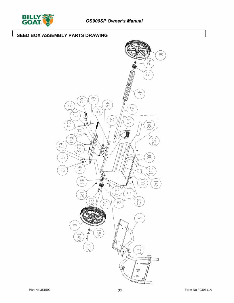
SEED BOX ASSEMBLY PARTS DRAWING

Part No 351502 Form No F030311A
23
OS900SP Owner’s Manual
SEED BOX ASSEMBLY PARTS LIST
OS900SPH OS900SPS
ITEM NO. DESCRIPTION PART NO. QTY PART NO. QTY
5 FRAME SUPPORT OS900SP WA 351102 1 351102 1
6 SEED BOX WA 351103 1 351103 1
10 FRONT WHEEL 14" ASSY 351013 2 351013 2
12 BEARING & FLANGETTE ASSY 850232 4 850232 4
27 AXLE SEED BOX 351223 1 351223 1
44 WHEEL PADDLE SEED WA 351105 1 351105 1
45 PLATE SEED CONTROL OS900SP 351220 1 351220 1
46 BRACKET CONTROL SEED RATE 351222 1 351222 1
48 SPRING EXTENSION .468 X 5.25 440130 1 440130 1
55 SPACER SEED BOX AXLE OS900SP 351408 2 351408 2
63 SPACER SEED PLATE OS900SP 351253 8 351253 8
64 CAM SEED RATE 351265 1 351265 1
65 KNOB WING 5/16" - 18 890108 1 890108 1
66 LABEL SEED FLOW RATE 351503 1 351503 1
83 CLAMP ROUTING FUEL LINE 791070 1 791070 1
100 SCREW 1/4" - 20 X .75 HWH 8041004 8 8041004 8
115 WASHER 1/4" SAE 8172007 8 8172007 8
117 LOCK NUT 1/4-20 8160001 8 8160001 8
125 NUT 5/16"-18 SER HEX WASHER FLNG ZP350346 8 350346 8
129 BOLT CARRIAGE 5/16"-18 X 3/4" ZP 8024039 8 8024039 8
138 CABLE CLUTCH SEEDING CONTROL 351221 1 351221 1
145 LABEL WARNING OPEI 400424 1 400424 1
147 PIN CLEVIS 1/4" X .61 350399 1 350399 1
148 LABEL BADGING OS900SP 351505 1 351505 1
149 WASHER LOCK 5/16" TWISTED TOOTH HEAVY430298 2 430298 2
150 PIN CLIP HITCH 0.051 X 3/4" 440193 1 440193 1
151 BOLT CARRIAGE 5/16"-18 X 1 1/4" ZP 8024041 1 8024041 1
152 SCREWCAP 5/16"-18 X 3/4" HCS ZP 8041026 2 8041026 2
153 NUT LOCK 5/16"-18 LT WT TH ZP 8161041 1 8161041 1
154 WASHER FENDER 5/16" 8172020 2 8172020 2
192 SEED BOX WAS OS900SP W/LABELS 351604 1 351604 1
Part No 351502 Form No F030311A 24
OS900SP Owner’s Manual
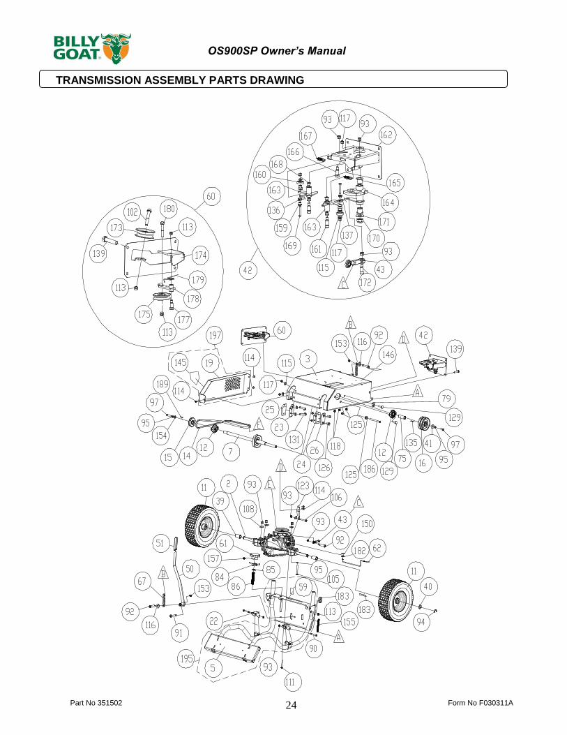
TRANSMISSION ASSEMBLY PARTS DRAWING
Part No 351502 Form No F030311A
25
OS900SP Owner’s Manual
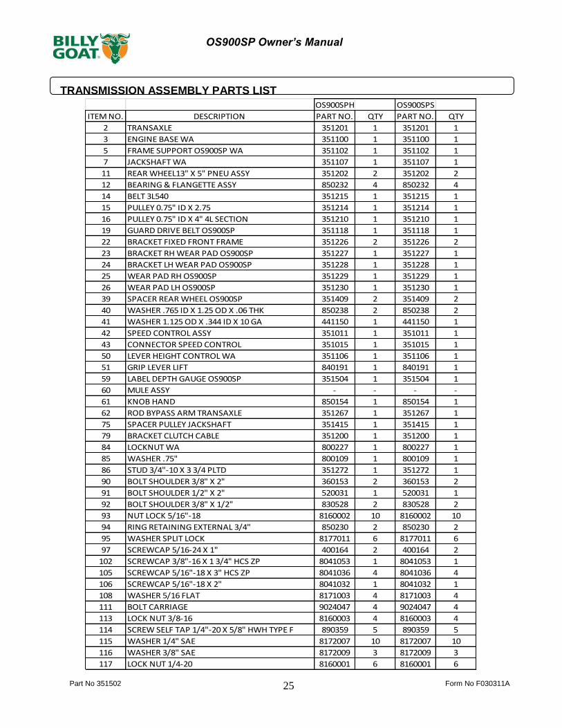
TRANSMISSION ASSEMBLY PARTS LIST
OS900SPH OS900SPS
ITEM NO. DESCRIPTION PART NO. QTY PART NO. QTY
2 TRANSAXLE 351201 1 351201 1
3 ENGINE BASE WA 351100 1 351100 1
5 FRAME SUPPORT OS900SP WA 351102 1 351102 1
7 JACKSHAFT WA 351107 1 351107 1
11 REAR WHEEL13" X 5" PNEU ASSY 351202 2 351202 2
12 BEARING & FLANGETTE ASSY 850232 4 850232 4
14 BELT 3L540 351215 1 351215 1
15 PULLEY 0.75" ID X 2.75 351214 1 351214 1
16 PULLEY 0.75" ID X 4" 4L SECTION 351210 1 351210 1
19 GUARD DRIVE BELT OS900SP 351118 1 351118 1
22 BRACKET FIXED FRONT FRAME 351226 2 351226 2
23 BRACKET RH WEAR PAD OS900SP 351227 1 351227 1
24 BRACKET LH WEAR PAD OS900SP 351228 1 351228 1
25 WEAR PAD RH OS900SP 351229 1 351229 1
26 WEAR PAD LH OS900SP 351230 1 351230 1
39 SPACER REAR WHEEL OS900SP 351409 2 351409 2
40 WASHER .765 ID X 1.25 OD X .06 THK 850238 2 850238 2
41 WASHER 1.125 OD X .344 ID X 10 GA 441150 1 441150 1
42 SPEED CONTROL ASSY 351011 1 351011 1
43 CONNECTOR SPEED CONTROL 351015 1 351015 1
50 LEVER HEIGHT CONTROL WA 351106 1 351106 1
51 GRIP LEVER LIFT 840191 1 840191 1
59 LABEL DEPTH GAUGE OS900SP 351504 1 351504 1
60 MULE ASSY - - - -
61 KNOB HAND 850154 1 850154 1
62 ROD BYPASS ARM TRANSAXLE 351267 1 351267 1
75 SPACER PULLEY JACKSHAFT 351415 1 351415 1
79 BRACKET CLUTCH CABLE 351200 1 351200 1
84 LOCKNUT WA 800227 1 800227 1
85 WASHER .75" 800109 1 800109 1
86 STUD 3/4"-10 X 3 3/4 PLTD 351272 1 351272 1
90 BOLT SHOULDER 3/8" X 2" 360153 2 360153 2
91 BOLT SHOULDER 1/2" X 2" 520031 1 520031 1
92 BOLT SHOULDER 3/8" X 1/2" 830528 2 830528 2
93 NUT LOCK 5/16"-18 8160002 10 8160002 10
94 RING RETAINING EXTERNAL 3/4" 850230 2 850230 2
95 WASHER SPLIT LOCK 8177011 6 8177011 6
97 SCREWCAP 5/16-24 X 1" 400164 2 400164 2
102 SCREWCAP 3/8"-16 X 1 3/4" HCS ZP 8041053 1 8041053 1
105 SCREWCAP 5/16"-18 X 3" HCS ZP 8041036 4 8041036 4
106 SCREWCAP 5/16"-18 X 2" 8041032 1 8041032 1
108 WASHER 5/16 FLAT 8171003 4 8171003 4
111 BOLT CARRIAGE 9024047 4 9024047 4
113 LOCK NUT 3/8-16 8160003 4 8160003 4
114 SCREW SELF TAP 1/4"-20 X 5/8" HWH TYPE F 890359 5 890359 5
115 WASHER 1/4" SAE 8172007 10 8172007 10
116 WASHER 3/8" SAE 8172009 3 8172009 3
117 LOCK NUT 1/4-20 8160001 6 8160001 6
Part No 351502 Form No F030311A 26
OS900SP Owner’s Manual
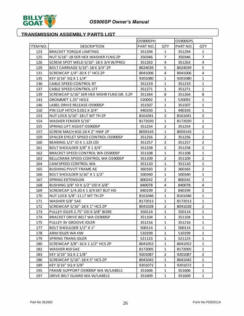
TRANSMISSION ASSEMBLY PARTS LIST
OS900SPH OS900SPS
ITEM NO. DESCRIPTION PART NO. QTY PART NO. QTY
123 BRACKET TORQUE LIMITING 351294 1 351294 1
125 NUT 5/16"-18 SER HEX WASHER FLNG ZP 350346 7 350346 7
126 SCREW SPOT WELD 5/16"-18 X 3/4 W/PROJ 351263 4 351263 4
129 BOLT CARRIAGE 5/16"-18 X 3/4" ZP 8024039 5 8024039 5
131 SCREWCAP 1/4"-20 X 1" HCS ZP 8041006 4 8041006 4
135 KEY 3/16" SQ X 1 1/4" 9201080 1 9201080 1
136 CABLE SPEED CONTROL RT 351219 1 351219 1
137 CABLE SPEED CONTROL LFT 351271 1 351271 1
139 SCREWCAP 5/16" SER HEX WSHR FLNG GR. 5 ZP 351264 8 351264 8
143 GROMMET 1.25" HOLE 520092 1 520092 1
146 LABEL DRIVE RELEASE OS900SP 351507 1 351507 1
150 PIN CLIP HITCH 0.051 X 3/4" 440193 1 440193 1
153 NUT LOCK 5/16"-18 LT WT TH ZP 8161041 2 8161041 2
154 WASHER FENDER 5/16" 8172020 1 8172020 1
155 SPRING LIFT ASSIST OS900SP 351254 2 351254 2
157 SCREW MACH #10-24 X 2" HWF ZP 8059143 1 8059143 1
159 SPACER EYELET SPEED CONTROL OS900SP 351256 2 351256 2
160 BEARING 1/2" ID X 1.125 OD 351257 2 351257 2
161 BOLT SHOULDER 3/8" X 1 3/4" 351258 2 351258 2
162 BRACKET SPEED CONTROL WA OS900SP 351108 1 351108 1
163 BELLCRANK SPEED CONTROL WA OS900SP 351109 2 351109 2
164 CAM SPEED CONTROL WA 351110 1 351110 1
165 BUSHING PIVOT FRAME AE 360183 2 360183 2
166 BOLT SHOULDER 5/16" X 1 1/2" 500340 1 500340 1
167 SPRING EXTENSION 800242 2 800242 2
168 BUSHING 3/8" ID X 1/2" OD X 3/8" 840078 4 840078 4
169 SCREWCAP 1/4-20 X 1 3/4 SKT BUT HD 840199 2 840199 2
170 NUT LOCK 5/8"-11 LT WT TH ZP 8161046 1 8161046 1
171 WASHER 5/8" SAE 8172013 1 8172013 1
172 SCREWCAP 5/16"-18 X 1" HCS ZP 8041028 2 8041028 2
173 PULLEY IDLER 2.75" OD X 3/8" BORE 350114 1 350114 1
174 BRACKET DRIVE BELT WA OS900SP 351104 1 351104 1
175 PULLEY 3V GROOVE IDLER 351216 1 351216 1
177 BOLT SHOULDER 1/2" X 1" 500114 1 500114 1
178 ARM IDLER WA HW 510199 1 510199 1
179 SPRING TRANS IDLER 521123 1 521123 1
180 SCREWCAP 3/8"-16 X 1 1/2" HCS ZP 8041052 1 8041052 1
182 WASHER #10 SAE 8172005 1 8172005 1
183 KEY 3/16" SQ X 2 1/8" 9201087 2 9201087 2
186 SCREWCAP 5/16"-18 X 5" HCS ZP 8041042 1 8041042 1
189 KEY 3/16" SQ X 5/8" 9201072 1 9201072 1
195 FRAME SUPPORT OS900SP WA W/LABELS 351606 1 351606 1
197 DRIVE BELT GUARD WA W/LABELS 351609 1 351609 1
Part No 351502 Form No F030311A
27
OS900SP Owner’s Manual
MAINTENANCE RECORD
Date Service Performed

Part No 351502 Form No F030311A 28
OS900SP Owner’s Manual