Embed Size (px)
Citation preview
BIG-IP® Global Traffic Manager™:Implementations
Version 11.6

Table of Contents
Legal Notices and Acknowledgments......................................................................................9
Legal Notices.....................................................................................................................9
Acknowledgments............................................................................................................10
Integrating BIG-IP GTM Into a Network with BIG-IP LTM Systems.......................................15
Overview: Integrating GTM with other BIG-IP systems on a network..............................15
About iQuery and communications between BIG-IP systems...............................15
Task summary..................................................................................................................15
Defining a data center...........................................................................................16
Defining BIG-IP GTM systems..............................................................................16
Defining BIG-IP LTM systems...............................................................................17
Running the big3d_install script............................................................................19
Implementation result.......................................................................................................19
Integrating BIG-IP LTM Into a Network with BIG-IP GTM Systems.......................................21
Overview: Integrating BIG-IP LTM with BIG-IP GTM systems.........................................21
Defining a data center...........................................................................................21
Defining BIG-IP GTM systems..............................................................................22
Defining BIG-IP LTM systems...............................................................................23
Running the bigip_add script.................................................................................24
Implementation result.......................................................................................................25
Adding a new BIG-IP GTM to a GTM Synchronization Group...............................................27
Overview: Adding a BIG-IP GTM system to a GTM synchronization group.....................27
Enabling synchronization on the existing GTM.....................................................27
Creating a data center on the existing GTM..........................................................28
Defining a server on the existing GTM..................................................................28
Running the gtm_add script..................................................................................30
Implementation result.......................................................................................................30
Delegating DNS Traffic to BIG-IP GTM....................................................................................31
Overview: Delegating DNS traffic to wide IPs on BIG-IP GTM........................................31
About listeners.......................................................................................................31
Task summary..................................................................................................................32
Creating a delegated zone on a local DNS server................................................32
Creating listeners to handle traffic for wide IPs.....................................................32
Implementation result.......................................................................................................33
3
Table of Contents

Redirecting DNS Queries Using a CNAME Record................................................................35
Overview: Redirecting DNS queries using a CNAME record ..........................................35
About CNAME records..........................................................................................35
Task summary..................................................................................................................35
Creating a pool using a CNAME...........................................................................35
Creating a wide IP with a CNAME pool ................................................................36
Viewing statistics for wide IP CNAME resolutions.................................................36
Implementation result.......................................................................................................36
Replacing a DNS Server with BIG-IP GTM..............................................................................37
Overview: Replacing a DNS server with BIG-IP GTM.....................................................37
About listeners.......................................................................................................37
Task summary..................................................................................................................37
Configuring BIND servers to allow zone transfers.................................................38
Performing zone transfers from the legacy DNS server........................................38
Creating a self IP address using the IP address of the legacy DNS server..........39
Designating GTM as the primary server for the zone............................................39
Creating listeners to alert GTM to DNS traffic destined for the system.................40
Creating a wide IP ................................................................................................40
Implementation result.......................................................................................................41
Placing BIG-IP GTM in Front of a DNS Server........................................................................43
Overview: Configuring GTM to screen traffic to an existing DNS server.........................43
About listeners.......................................................................................................43
About wildcard listeners........................................................................................44
Task summary..................................................................................................................44
Placing BIG-IP GTM on your network to forward traffic.........................................44
Creating listeners to forward traffic to a DNS server ............................................44
Creating a wide IP ................................................................................................45
Implementation result.......................................................................................................45
Placing BIG-IP GTM in front of a Pool of DNS Servers..........................................................47
Overview: Screening and forwarding non-wide IP traffic to a pool of DNS servers.........47
About listeners.......................................................................................................47
Task summary..................................................................................................................47
Creating a pool of local DNS servers....................................................................48
Creating listeners that alert GTM to DNS queries for a pool of DNS servers.......48
Implementation result.......................................................................................................49
Configuring GTM to Determine PGW Health and Availability...............................................51
Overview: Configuring GTM to determine packet gateway health and availability...........51
Defining a data center...........................................................................................52
4
Table of Contents
Defining BIG-IP GTM systems..............................................................................52
Defining packet gateway systems.........................................................................53
Creating listeners to identify DNS traffic for an APN.............................................54
Creating a custom GTP monitor............................................................................55
Creating a pool of packet gateway systems..........................................................56
Configuring a wide IP for load balancing APN lookups.........................................56
Configuring GTM on a Network with One Route Domain.....................................................59
Overview: How do I deploy BIG-IP GTM on a network with one route domain?..............59
Creating VLANs for a route domain on BIG-IP LTM..............................................60
Creating a route domain on the BIG-IP system.....................................................60
Creating a self IP address for a route domain on BIG-IP LTM..............................61
Defining a server for a route domain on BIG-IP GTM...........................................62
Implementation result.......................................................................................................63
Configuring GTM on a Network with Multiple Route Domains.............................................65
Overview: How do I deploy BIG-IP GTM on a network with multiple route domains?......65
Creating VLANs for a route domain on BIG-IP LTM..............................................67
Creating a route domain on BIG-IP LTM...............................................................67
Creating a self IP address for a route domain on BIG-IP LTM..............................68
Defining a server for a route domain on BIG-IP GTM...........................................68
Implementation result.......................................................................................................69
Setting Up a BIG-IP GTM Redundant System Configuration................................................71
Overview: Configuring a BIG-IP GTM redundant system................................................71
Defining an NTP server.........................................................................................71
Creating listeners to identify DNS traffic................................................................72
Defining a data center...........................................................................................72
Defining a server to represent each BIG-IP system .............................................73
Enabling global traffic configuration synchronization............................................73
Running the gtm_add script .................................................................................74
Authenticating with SSL Certificates Signed by a Third Party.............................................75
Overview: Authenticating with SSL certificates signed by a third party...........................75
About SSL authentication levels............................................................................75
Configuring Level 1 SSL authentication...........................................................................75
Importing the device certificate signed by a CA server.........................................75
Importing the root certificate for the gtmd agent...................................................76
Importing the root certificate for the big3d agent...................................................76
Verifying the certificate exchange..........................................................................77
Implementation Results....................................................................................................77
Configuring certificate chain SSL authentication.............................................................77
Creating a certificate chain file .............................................................................77
5
Table of Contents
Importing the device certificate from the last CA server in the chain....................77
Importing a certificate chain file for the gtmd agent..............................................78
Importing a certificate chain for the big3d agent...................................................78
Verifying the certificate chain exchange................................................................79
Implementation result.......................................................................................................79
Configuring a TTL in a DNS NoError Response....................................................................81
Overview: Configuring a TTL in an IPv6 DNS NoError Response...................................81
About SOA records and negative caching............................................................81
Task summary..................................................................................................................81
Creating a pool......................................................................................................81
Creating a wide IP that provides for negative caching .........................................82
Implementation result.......................................................................................................82
Configuring Device-Specific Probing and Statistics Collection...........................................83
Overview: Configuring device-specific probing and statistics collection..........................83
About Prober pools................................................................................................83
About Prober pool status.......................................................................................84
About Prober pool statistics...................................................................................84
Task summary..................................................................................................................84
Defining a data center...........................................................................................85
Defining a server...................................................................................................85
Creating a Prober pool..........................................................................................86
Assigning a Prober pool to a data center..............................................................87
Assigning a Prober pool to a server......................................................................87
Viewing Prober pool statistics and status..............................................................88
Determining which Prober pool member marked a resource down......................88
Implementation result.......................................................................................................88
Configuring How and When GTM Saves Configuration Changes........................................89
Overview: Configuring how and when GTM saves configuration changes......................89
Changing the automatic configuration save timeout..............................................89
Enabling manual saves of configuration changes.................................................90
Configuring how and when GTM saves configuration changes using tmsh..........90
Configuring Logging of Global Server Load Balancing Decisions......................................93
About logging global server load-balancing decisions.....................................................93
Configuring logs for global server load-balancing decisions ................................93
Monitoring Third-Party Servers with SNMP...........................................................................95
Overview: SNMP monitoring of third-party servers..........................................................95
Creating an SNMP monitor...................................................................................95
Defining a third-party host server that is running SNMP.......................................95
6
Table of Contents
Implementation result.......................................................................................................96
Troubleshooting a BIG-IP System with a Rate-Limited License...........................................97
About GTM and DNS rate-limited license statistics.........................................................97
Viewing rate-limited license statistics....................................................................97
How to Diagnose Network Connection Issues.......................................................................99
Diagnosing network connection issues............................................................................99
Viewing iQuery statistics ......................................................................................99
iQuery statistics descriptions.................................................................................99
7
Table of Contents

8
Table of Contents
Legal Notices and Acknowledgments
Legal Notices
Publication Date
This document was published on September 13, 2017.
Publication Number
MAN-0531-00
Copyright
Copyright © 2014-2017, F5 Networks, Inc. All rights reserved.
F5 Networks, Inc. (F5) believes the information it furnishes to be accurate and reliable. However, F5 assumesno responsibility for the use of this information, nor any infringement of patents or other rights of thirdparties which may result from its use. No license is granted by implication or otherwise under any patent,copyright, or other intellectual property right of F5 except as specifically described by applicable userlicenses. F5 reserves the right to change specifications at any time without notice.
Trademarks
AAM, Access Policy Manager, Advanced Client Authentication, Advanced Firewall Manager, AdvancedRouting, AFM, Application Acceleration Manager, Application Security Manager, APM, ARX, AskF5,ASM, BIG-IP, BIG-IQ, Cloud Extender, CloudFucious, Cloud Manager, Clustered Multiprocessing, CMP,COHESION, Data Manager, DevCentral, DevCentral [DESIGN], DNS Express, DSC, DSI, Edge Client,Edge Gateway, Edge Portal, ELEVATE, EM, EnterpriseManager, ENGAGE, F5, F5 [DESIGN], F5 Certified[DESIGN], F5 Networks, F5 SalesXchange [DESIGN], F5 Synthesis, f5 Synthesis, F5 Synthesis [DESIGN],F5 TechXchange [DESIGN], Fast Application Proxy, Fast Cache, FirePass, Global Traffic Manager, GTM,GUARDIAN, iApps, IBR, iCall, Intelligent Browser Referencing, Intelligent Compression, IPv6 Gateway,iControl, iHealth, iQuery, iRules, iRules OnDemand, iSession, L7 Rate Shaping, LC, Link Controller,LineRate, LineRate Systems [DESIGN], Local Traffic Manager, LROS, LTM, Message Security Manager,MobileSafe, MSM, OneConnect, Packet Velocity, PEM, Policy Enforcement Manager, Protocol SecurityManager, PSM, Real Traffic Policy Builder, SalesXchange, ScaleN, SDAC (except in Japan), SDC, SignallingDelivery Controller, Solutions for an application world, Software Designed Applications Services, SSLAcceleration, StrongBox, SuperVIP, SYN Check, TCP Express, TDR, TechXchange, TMOS, TotALL,Traffic Management Operating System, Traffix (except Germany), Traffix [DESIGN] (except Germany),Transparent Data Reduction, UNITY, VAULT, vCMP, VE F5 [DESIGN], Versafe, Versafe [DESIGN],VIPRION, Virtual Clustered Multiprocessing, WebSafe, and ZoneRunner, are trademarks or service marksof F5 Networks, Inc., in the U.S. and other countries, and may not be used without F5's express writtenconsent.
All other product and company names herein may be trademarks of their respective owners.
Patents
This product may be protected by one or more patents indicated at:http://www.f5.com/about/guidelines-policies/patents
Export Regulation Notice
This product may include cryptographic software. Under the Export Administration Act, the United Statesgovernment may consider it a criminal offense to export this product from the United States.
RF Interference Warning
This is a Class A product. In a domestic environment this product may cause radio interference, in whichcase the user may be required to take adequate measures.
FCC Compliance
This equipment has been tested and found to comply with the limits for a Class A digital device pursuantto Part 15 of FCC rules. These limits are designed to provide reasonable protection against harmfulinterference when the equipment is operated in a commercial environment. This unit generates, uses, andcan radiate radio frequency energy and, if not installed and used in accordance with the instruction manual,may cause harmful interference to radio communications. Operation of this equipment in a residential areais likely to cause harmful interference, in which case the user, at his own expense, will be required to takewhatever measures may be required to correct the interference.
Anymodifications to this device, unless expressly approved by themanufacturer, can void the user's authorityto operate this equipment under part 15 of the FCC rules.
Canadian Regulatory Compliance
This Class A digital apparatus complies with Canadian ICES-003.
Standards Compliance
This product conforms to the IEC, European Union, ANSI/UL and Canadian CSA standards applicable toInformation Technology products at the time of manufacture.
Acknowledgments
This product includes software developed by Gabriel Forté.
This product includes software developed by Bill Paul.
This product includes software developed by Jonathan Stone.
This product includes software developed by Manuel Bouyer.
This product includes software developed by Paul Richards.
This product includes software developed by the NetBSD Foundation, Inc. and its contributors.
This product includes software developed by the Politecnico di Torino, and its contributors.
This product includes software developed by the Swedish Institute of Computer Science and its contributors.
This product includes software developed by the University of California, Berkeley and its contributors.
This product includes software developed by the Computer Systems Engineering Group at the LawrenceBerkeley Laboratory.
This product includes software developed by Christopher G. Demetriou for the NetBSD Project.
This product includes software developed by Adam Glass.
This product includes software developed by Christian E. Hopps.
10
Legal Notices and Acknowledgments

This product includes software developed by Dean Huxley.
This product includes software developed by John Kohl.
This product includes software developed by Paul Kranenburg.
This product includes software developed by Terrence R. Lambert.
This product includes software developed by Philip A. Nelson.
This product includes software developed by Herb Peyerl.
This product includes software developed by Jochen Pohl for the NetBSD Project.
This product includes software developed by Chris Provenzano.
This product includes software developed by Theo de Raadt.
This product includes software developed by David Muir Sharnoff.
This product includes software developed by SigmaSoft, Th. Lockert.
This product includes software developed for the NetBSD Project by Jason R. Thorpe.
This product includes software developed by Jason R. Thorpe for AndCommunications, http://www.and.com.
This product includes software developed for the NetBSD Project by Frank Van der Linden.
This product includes software developed for the NetBSD Project by John M. Vinopal.
This product includes software developed by Christos Zoulas.
This product includes software developed by the University of Vermont and State Agricultural College andGarrett A. Wollman.
This product includes software developed by Balazs Scheidler ([email protected]), which is protected underthe GNU Public License.
This product includes software developed by Niels Mueller ([email protected]), which is protected underthe GNU Public License.
In the following statement, "This software" refers to the Mitsumi CD-ROM driver: This software wasdeveloped by Holger Veit and Brian Moore for use with 386BSD and similar operating systems. "Similaroperating systems" includes mainly non-profit oriented systems for research and education, including butnot restricted to NetBSD, FreeBSD, Mach (by CMU).
This product includes software developed by the Apache Group for use in the Apache HTTP server project(http://www.apache.org/).
This product includes software licensed from Richard H. Porter under the GNU Library General PublicLicense (© 1998, Red Hat Software), www.gnu.org/copyleft/lgpl.html.
This product includes the standard version of Perl software licensed under the Perl Artistic License (© 1997,1998 TomChristiansen and Nathan Torkington). All rights reserved. Youmay find the most current standardversion of Perl at http://www.perl.com.
This product includes software developed by Jared Minch.
This product includes software developed by the OpenSSL Project for use in the OpenSSL Toolkit(http://www.openssl.org/).
This product includes cryptographic software written by Eric Young ([email protected]).
This product contains software based on oprofile, which is protected under the GNU Public License.
This product includes RRDtool software developed by Tobi Oetiker (http://www.rrdtool.com/index.html)and licensed under the GNU General Public License.
This product contains software licensed from Dr. Brian Gladman under the GNU General Public License(GPL).
11
BIG-IP® Global Traffic Manager™: Implementations

This product includes software developed by the Apache Software Foundation (http://www.apache.org/).
This product includes Hypersonic SQL.
This product contains software developed by the Regents of the University of California, SunMicrosystems,Inc., Scriptics Corporation, and others.
This product includes software developed by the Internet Software Consortium.
This product includes software developed by Nominum, Inc. (http://www.nominum.com).
This product contains software developed by Broadcom Corporation, which is protected under the GNUPublic License.
This product contains software developed byMaxMind LLC, and is protected under the GNULesser GeneralPublic License, as published by the Free Software Foundation.
This product includes unbound software from NLnetLabs. Copyright ©2007. All rights reserved.
Redistribution and use in source and binary forms, with or without modification, are permitted providedthat the following conditions are met:
• Redistributions of source code must retain the above copyright notice, this list of conditions and thefollowing disclaimer.
• Redistributions in binary form must reproduce the above copyright notice, this list of conditions and thefollowing disclaimer in the documentation and/or other materials provided with the distribution.
• Neither the name of NLnetLabs nor the names of its contributors may be used to endorse or promoteproducts derived from this software without specific prior written permission.
THIS SOFTWARE IS PROVIDED BY THE COPYRIGHT HOLDERS AND CONTRIBUTORS "AS IS"AND ANY EXPRESS OR IMPLIED WARRANTIES, INCLUDING, BUT NOT LIMITED TO, THEIMPLIEDWARRANTIES OFMERCHANTABILITYAND FITNESS FORA PARTICULAR PURPOSEARE DISCLAIMED. IN NO EVENT SHALL THE COPYRIGHT OWNER OR CONTRIBUTORS BELIABLE FOR ANY DIRECT, INDIRECT, INCIDENTAL, SPECIAL, EXEMPLARY, ORCONSEQUENTIAL DAMAGES (INCLUDING, BUT NOT LIMITED TO, PROCUREMENT OFSUBSTITUTE GOODS OR SERVICES; LOSS OF USE, DATA, OR PROFITS; OR BUSINESSINTERRUPTION) HOWEVER CAUSED AND ON ANY THEORY OF LIABILITY, WHETHER INCONTRACT, STRICTLIABILITY,ORTORT (INCLUDINGNEGLIGENCEOROTHERWISE)ARISINGIN ANYWAY OUT OF THE USE OF THIS SOFTWARE, EVEN IF ADVISED OF THE POSSIBILITYOF SUCH DAMAGE.
This product includes Intel QuickAssist kernel module, library, and headers software licensed under theGNU General Public License (GPL).
This product includes software licensed fromGerald Combs ([email protected]) under the GNUGeneralPublic License as published by the Free Software Foundation; either version 2 of the License, or any laterversion. Copyright ©1998 Gerald Combs.
This product includes software developed by Thomas Williams and Colin Kelley. Copyright ©1986 - 1993,1998, 2004, 2007
Permission to use, copy, and distribute this software and its documentation for any purpose with or withoutfee is hereby granted, provided that the above copyright notice appear in all copies and that both thatcopyright notice and this permission notice appear in supporting documentation. Permission to modify thesoftware is granted, but not the right to distribute the complete modified source code. Modifications are tobe distributed as patches to the released version. Permission to distribute binaries produced by compilingmodified sources is granted, provided you
1. distribute the corresponding source modifications from the released version in the form of a patch filealong with the binaries,
2. add special version identification to distinguish your version in addition to the base release versionnumber,
3. provide your name and address as the primary contact for the support of your modified version, and
12
Legal Notices and Acknowledgments

4. retain our contact information in regard to use of the base software.
Permission to distribute the released version of the source code alongwith corresponding sourcemodificationsin the form of a patch file is granted with same provisions 2 through 4 for binary distributions. This softwareis provided "as is" without express or implied warranty to the extent permitted by applicable law.
This product contains software developed by Google, Inc. Copyright ©2011 Google, Inc.
Permission is hereby granted, free of charge, to any person obtaining a copy of this software and associateddocumentation files (the "Software"), to deal in the Software without restriction, including without limitationthe rights to use, copy, modify, merge, publish, distribute, sublicense, and/or sell copies of the Software,and to permit persons to whom the Software is furnished to do so, subject to the following conditions:
The above copyright notice and this permission notice shall be included in all copies or substantial portionsof the Software.
THE SOFTWARE IS PROVIDED "AS IS", WITHOUT WARRANTY OF ANY KIND, EXPRESS ORIMPLIED, INCLUDING BUT NOT LIMITED TO THE WARRANTIES OF MERCHANTABILITY,FITNESS FOR A PARTICULAR PURPOSE ANDNONINFRINGEMENT. IN NO EVENT SHALL THEAUTHORS OR COPYRIGHT HOLDERS BE LIABLE FOR ANY CLAIM, DAMAGES OR OTHERLIABILITY, WHETHER IN ANACTIONOF CONTRACT, TORT OROTHERWISE, ARISING FROM,OUT OF OR IN CONNECTION WITH THE SOFTWARE OR THE USE OR OTHER DEALINGS INTHE SOFTWARE.
This product includes software developed by Digital Envoy, Inc.
This product includes software developed by Jeremy Ashkenas and DocumentCloud, and distributed underthe MIT license. Copyright © 2010-2013 Jeremy Ashkenas, DocumentCloud.
This product includes gson software, distributed under the Apache License version 2.0. Copyright ©2008-2011 Google Inc.
This product includes ec2-tools software, copyright © 2008, Amazon Web Services, and licensed under theAmazon Software License. A copy of the License is located at http://aws.amazon.com/asl/ .
This product includes jxrlib software, copyright ©2009 Microsoft Corp. All rights reserved. Distributedunder the new BSD license.
This product includes node-uuid software, copyright © 2010-2012, Robert Kieffer, and distributed underthe MIT license.
This product includes opencsv software, which is distributed under the Apache 2.0 license.
This product includes owasp-jave-encoder software, copyright © 2014, Jeff Ichnowski, and distributedunder the New BSD license.
13
BIG-IP® Global Traffic Manager™: Implementations

Integrating BIG-IP GTM Into a Network with BIG-IP LTMSystems
Overview: Integrating GTM with other BIG-IP systems on a network
You can add BIG-IP® Global Traffic Manager™ (GTM™) systems to a network in which BIG-IP® LocalTrafficManager™ (LTM®) systems and BIG-IP Link Controller™ systems are already present. This expandsyour load balancing and traffic management capabilities beyond the local area network. For thisimplementation to be successful, you must authorize communications between the systems.
Note: The GTM devices in a GTM synchronization group, and the LTM and Link Controller™ devices thatare configured to communicate with the devices in the GTM synchronization group must have TCP port4353 open through the firewall between the systems. The BIG-IP devices connect and communicate throughthis port.
About iQuery and communications between BIG-IP systems
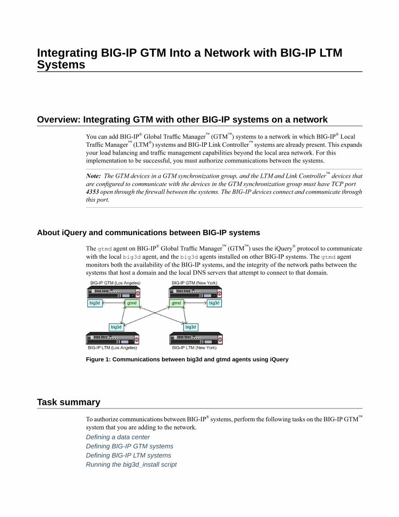
The gtmd agent on BIG-IP® Global Traffic Manager™ (GTM™) uses the iQuery® protocol to communicatewith the local big3d agent, and the big3d agents installed on other BIG-IP systems. The gtmd agentmonitors both the availability of the BIG-IP systems, and the integrity of the network paths between thesystems that host a domain and the local DNS servers that attempt to connect to that domain.
Figure 1: Communications between big3d and gtmd agents using iQuery
Task summary
To authorize communications between BIG-IP® systems, perform the following tasks on the BIG-IP GTM™
system that you are adding to the network.Defining a data centerDefining BIG-IP GTM systemsDefining BIG-IP LTM systemsRunning the big3d_install script
Defining a data center
On BIG-IP®GTM™, create a data center to contain the servers that reside on a subnet of your network.
1. On the Main tab, click DNS > GSLB > Data Centers.The Data Center List screen opens.
2. Click Create.The New Data Center screen opens.
3. In the Name field, type a name to identify the data center.
Important: The data center name is limited to 63 characters.
4. In the Location field, type the geographic location of the data center.5. In the Contact field, type the name of either the administrator or the department that manages the data
center.6. From the State list, select Enabled.7. Click Finished.
Now you can create server objects and assign them to this data center.
Repeat these steps to create additional data centers.
Defining BIG-IP GTM systems
Ensure that at least one data center exists in the configuration before you start creating a server.
On BIG-IP® GTM™, create a server object to represent the GTM system itself.
1. On the Main tab, click DNS > GSLB > Servers.The Server List screen opens.
2. Click Create.The New Server screen opens.
3. In the Name field, type a name for the server.
Important: Server names are limited to 63 characters.
4. From the Product list, select BIG-IP System (Single).The server type determines the metrics that the system can collect from the server.
5. In the Address List area, add the non-floating IP addresses of the server.You can add more than one IP address, depending on how the server interacts with the rest of yournetwork.
Important: You must use a self IP address for a BIG-IP system; you cannot use the management IPaddress.
6. From the Data Center list, select the data center where the server resides.7. In the Health Monitors area, assign the bigipmonitor to the server by moving it from the Available list
to the Selected list.8. From the Virtual Server Discovery list, select how you want virtual servers to be added to the system.
16
Integrating BIG-IP GTM Into a Network with BIG-IP LTM Systems
DescriptionOption
The system does not use the discovery feature to automatically add virtual servers.This is the default value. Use this option for a standalone GTM system or for a
Disabled
GTM/LTM® combo system when you plan to manually add virtual servers to thesystem, or if your network uses multiple route domains.
The system uses the discovery feature to automatically add virtual servers. Usethis option for a GTM/LTM combo system when you want the GTM system todiscover LTM virtual servers.
Enabled
The system uses the discovery feature to automatically add virtual servers anddoes not delete any virtual servers that already exist. Use this option for a
Enabled (NoDelete)
GTM/LTM combo system when you want the GTM system to discover LTMvirtual servers.
9. In the Virtual Server List area, if you selectedDisabled from theVirtual Server Discovery list, specifythe virtual servers that are resources on this server.a) In the Name field, type the name of the virtual server.b) In the Address field, type the IP address of the virtual server.c) From the Service Port list, select the port the server uses.d) Click Add.
10. From the Link Discovery list, select how you want links to be added to the system.DescriptionOption
The system does not use the discovery feature to automatically add links. Thisis the default value. Use this option for a standalone GTM system or for aGTM/LTM combo system when you plan to manually add links to the system.
Disabled
The system uses the discovery feature to automatically add links. Use this optionfor a GTM/LTM combo system when you want BIG-IP GTM to discover links.
Enabled
The system uses the discovery feature to automatically add links and does notdelete any links that already exist. Use this option for a GTM/LTM combo systemwhen you want GTM to discover links.
Enabled (NoDelete)
11. Click Create.The Server List screen opens displaying the new server in the list.
Defining BIG-IP LTM systems
On GTM™, define servers that represent the LTM® systems in your network.
1. On the Main tab, click DNS > GSLB > Servers.The Server List screen opens.
2. Click Create.The New Server screen opens.
3. In the Name field, type a name for the server.
Important: Server names are limited to 63 characters.
4. From the Product list, select either BIG-IP System (Single) or BIG-IP System (Redundant).The server type determines the metrics that the system can collect from the server.
17
BIG-IP® Global Traffic Manager™: Implementations
5. In the Address List area, add the non-floating IP addresses of the server.You can add more than one IP address, depending on how the server interacts with the rest of yournetwork.
Important: You must use a self IP address for a BIG-IP system; you cannot use the management IPaddress.
6. From the Data Center list, select the data center where the server resides.7. In the Health Monitors area, assign the bigipmonitor to the server by moving it from the Available list
to the Selected list.8. From the Virtual Server Discovery list, select how you want virtual servers to be added to the system.
DescriptionOption
The system does not use the discovery feature to automatically add virtual servers.This is the default value. Use this option for a standalone GTM system or for a
Disabled
GTM/LTM® combo system when you plan to manually add virtual servers to thesystem, or if your network uses multiple route domains.
The system uses the discovery feature to automatically add virtual servers. Usethis option for a GTM/LTM combo system when you want the GTM system todiscover LTM virtual servers.
Enabled
The system uses the discovery feature to automatically add virtual servers anddoes not delete any virtual servers that already exist. Use this option for a
Enabled (NoDelete)
GTM/LTM combo system when you want the GTM system to discover LTMvirtual servers.
9. In the Virtual Server List area, if you selectedDisabled from theVirtual Server Discovery list, specifythe virtual servers that are resources on this server.a) In the Name field, type the name of the virtual server.b) In the Address field, type the IP address of the virtual server.c) From the Service Port list, select the port the server uses.d) Click Add.
10. From the Link Discovery list, select how you want links to be added to the system.DescriptionOption
The system does not use the discovery feature to automatically add links. Thisis the default value. Use this option for a standalone GTM system or for aGTM/LTM combo system when you plan to manually add links to the system.
Disabled
The system uses the discovery feature to automatically add links. Use this optionfor a GTM/LTM combo system when you want BIG-IP GTM to discover links.
Enabled
The system uses the discovery feature to automatically add links and does notdelete any links that already exist. Use this option for a GTM/LTM combo systemwhen you want GTM to discover links.
Enabled (NoDelete)
11. Click Create.The Server List screen opens displaying the new server in the list.
18
Integrating BIG-IP GTM Into a Network with BIG-IP LTM Systems
Running the big3d_install script
Determine the self IP addresses of the BIG-IP® systems that you want to upgrade with the latest big3dagent. Ensure that port 22 is open on these systems.
Run the big3d_install script on the GTM™ system you are adding to your network. This upgrades thebig3d agents on the other BIG-IP systems on your network. It also instructs these systems to authenticatewith the other BIG-IP systems through the exchange of SSL certificates. For additional information aboutrunning the script, see SOL1332 on AskF5.com (www.askf5.com).
Note: You must perform this task from the command-line interface.
Important: All target BIG-IP systems must be running the same or an older version of BIG-IP software.
1. Log in as root to the BIG-IP GTM system you are adding to your network.2. Run this command to access tmsh:
tmsh
3. Run this command to run the big3d_install script:run gtm big3d_install <IP_addresses_of_target BIG-IP_systems>
The script instructs GTM to connect to each specified BIG-IP system.4. If prompted, enter the root password for each system.
The SSL certificates are exchanged, authorizing communications between the systems. The big3d agenton each system is upgraded to the same version as is installed on the GTM system from which you ran thescript.
Implementation result
You now have an implementation in which the BIG-IP® systems can communicate with each other. GTM™
can now use the other BIG-IP systems when load balancing DNS queries, and can acquire statistics andstatus information for the virtual servers these systems manage.
19
BIG-IP® Global Traffic Manager™: Implementations

Integrating BIG-IP LTM Into a Network with BIG-IP GTMSystems
Overview: Integrating BIG-IP LTM with BIG-IP GTM systems
You can add BIG-IP® Local Traffic Manager™ (LTM™) systems to a network in which BIG-IP® GlobalTraffic Manager™ (GTM™) systems are already present. This expands your load balancing and trafficmanagement capabilities to include the local area network. For this implementation to be successful, youmust authorize communications between the LTM and GTM systems. When the LTM and GTM systemsuse the same version of the big3d agent, you run the bigip_add utility to authorize communicationsbetween the systems.
Note: The BIG-IP GTM and BIG-IP LTM systems must have TCP port 4353 open through the firewallbetween the systems. The BIG-IP systems connect and communicate through this port.
Task summary
To authorize communications between BIG-IP® GTM and BIG-IP LTM systems, perform the followingtasks on GTM.Defining a data centerDefining BIG-IP GTM systemsDefining BIG-IP LTM systemsRunning the bigip_add script
Defining a data center
On BIG-IP®GTM™, create a data center to contain the servers that reside on a subnet of your network.
1. On the Main tab, click DNS > GSLB > Data Centers.The Data Center List screen opens.
2. Click Create.The New Data Center screen opens.
3. In the Name field, type a name to identify the data center.
Important: The data center name is limited to 63 characters.
4. In the Location field, type the geographic location of the data center.5. In the Contact field, type the name of either the administrator or the department that manages the data
center.6. From the State list, select Enabled.7. Click Finished.
Now you can create server objects and assign them to this data center.
Repeat these steps to create additional data centers.

Defining BIG-IP GTM systems
Ensure that at least one data center exists in the configuration before you start creating a server.
On BIG-IP® GTM™, create a server object to represent the GTM system itself.
1. On the Main tab, click DNS > GSLB > Servers.The Server List screen opens.
2. Click Create.The New Server screen opens.
3. In the Name field, type a name for the server.
Important: Server names are limited to 63 characters.
4. From the Product list, select BIG-IP System (Single).The server type determines the metrics that the system can collect from the server.
5. In the Address List area, add the non-floating IP addresses of the server.You can add more than one IP address, depending on how the server interacts with the rest of yournetwork.
Important: You must use a self IP address for a BIG-IP system; you cannot use the management IPaddress.
6. From the Data Center list, select the data center where the server resides.7. In the Health Monitors area, assign the bigipmonitor to the server by moving it from the Available list
to the Selected list.8. From the Virtual Server Discovery list, select how you want virtual servers to be added to the system.
DescriptionOption
The system does not use the discovery feature to automatically add virtual servers.This is the default value. Use this option for a standalone GTM system or for a
Disabled
GTM/LTM® combo system when you plan to manually add virtual servers to thesystem, or if your network uses multiple route domains.
The system uses the discovery feature to automatically add virtual servers. Usethis option for a GTM/LTM combo system when you want the GTM system todiscover LTM virtual servers.
Enabled
The system uses the discovery feature to automatically add virtual servers anddoes not delete any virtual servers that already exist. Use this option for a
Enabled (NoDelete)
GTM/LTM combo system when you want the GTM system to discover LTMvirtual servers.
9. In the Virtual Server List area, if you selectedDisabled from theVirtual Server Discovery list, specifythe virtual servers that are resources on this server.a) In the Name field, type the name of the virtual server.b) In the Address field, type the IP address of the virtual server.c) From the Service Port list, select the port the server uses.d) Click Add.
10. From the Link Discovery list, select how you want links to be added to the system.
22
Integrating BIG-IP LTM Into a Network with BIG-IP GTM Systems
DescriptionOption
The system does not use the discovery feature to automatically add links. Thisis the default value. Use this option for a standalone GTM system or for aGTM/LTM combo system when you plan to manually add links to the system.
Disabled
The system uses the discovery feature to automatically add links. Use this optionfor a GTM/LTM combo system when you want BIG-IP GTM to discover links.
Enabled
The system uses the discovery feature to automatically add links and does notdelete any links that already exist. Use this option for a GTM/LTM combo systemwhen you want GTM to discover links.
Enabled (NoDelete)
11. Click Create.The Server List screen opens displaying the new server in the list.
Defining BIG-IP LTM systems
On GTM™, define servers that represent the LTM® systems in your network.
1. On the Main tab, click DNS > GSLB > Servers.The Server List screen opens.
2. Click Create.The New Server screen opens.
3. In the Name field, type a name for the server.
Important: Server names are limited to 63 characters.
4. From the Product list, select either BIG-IP System (Single) or BIG-IP System (Redundant).The server type determines the metrics that the system can collect from the server.
5. In the Address List area, add the non-floating IP addresses of the server.You can add more than one IP address, depending on how the server interacts with the rest of yournetwork.
Important: You must use a self IP address for a BIG-IP system; you cannot use the management IPaddress.
6. From the Data Center list, select the data center where the server resides.7. In the Health Monitors area, assign the bigipmonitor to the server by moving it from the Available list
to the Selected list.8. From the Virtual Server Discovery list, select how you want virtual servers to be added to the system.
DescriptionOption
The system does not use the discovery feature to automatically add virtual servers.This is the default value. Use this option for a standalone GTM system or for a
Disabled
GTM/LTM® combo system when you plan to manually add virtual servers to thesystem, or if your network uses multiple route domains.
The system uses the discovery feature to automatically add virtual servers. Usethis option for a GTM/LTM combo system when you want the GTM system todiscover LTM virtual servers.
Enabled
23
BIG-IP® Global Traffic Manager™: Implementations
DescriptionOption
The system uses the discovery feature to automatically add virtual servers anddoes not delete any virtual servers that already exist. Use this option for a
Enabled (NoDelete)
GTM/LTM combo system when you want the GTM system to discover LTMvirtual servers.
9. In the Virtual Server List area, if you selectedDisabled from theVirtual Server Discovery list, specifythe virtual servers that are resources on this server.a) In the Name field, type the name of the virtual server.b) In the Address field, type the IP address of the virtual server.c) From the Service Port list, select the port the server uses.d) Click Add.
10. From the Link Discovery list, select how you want links to be added to the system.DescriptionOption
The system does not use the discovery feature to automatically add links. Thisis the default value. Use this option for a standalone GTM system or for aGTM/LTM combo system when you plan to manually add links to the system.
Disabled
The system uses the discovery feature to automatically add links. Use this optionfor a GTM/LTM combo system when you want BIG-IP GTM to discover links.
Enabled
The system uses the discovery feature to automatically add links and does notdelete any links that already exist. Use this option for a GTM/LTM combo systemwhen you want GTM to discover links.
Enabled (NoDelete)
11. Click Create.The Server List screen opens displaying the new server in the list.
Running the bigip_add script
Determine the self IP addresses of the LTM® systems that you want to communicate with GTM™.
Run the bigip_add script on the GTM system you are installing on a network that includes other BIG-IP®
systems of the same version. This script exchanges SSL certificates so that each system is authorized tocommunicate with the other. For additional information about running the script, see SOL13312 onAskF5.com (www.askf5.com).
Note: The BIG-IP GTM and BIG-IP LTM systems must have TCP port 22 open for the script to work. Youmust perform this task from the command-line interface.You must perform this task from the command-lineinterface.
1. Log in as root to the GTM system you are installing on your network.2. Run this command to access tmsh.
tmsh
3. Run this command to run the bigip_add utility:run gtm bigip_add <IP_addresses_of_BIG-IP_LTM_systems>
The utility exchanges SSL certificates so that each system is authorized to communicate with the other.
The specified BIG-IP systems can now communicate with GTM.
24
Integrating BIG-IP LTM Into a Network with BIG-IP GTM Systems

Implementation result
You now have an implementation in which the BIG-IP® systems can communicate with each other. BIG-IPGTM™ can now use the other BIG-IP systems when load balancing DNS queries, and can acquire statisticsand status information for the virtual servers the other BIG-IP systems manage.
25
BIG-IP® Global Traffic Manager™: Implementations

Adding a new BIG-IP GTM to a GTM Synchronization Group
Overview: Adding a BIG-IP GTM system to a GTM synchronization group
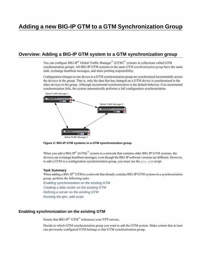
You can configure BIG-IP® Global Traffic Manager™ (GTM)™ systems in collections called GTMsynchronization groups. All BIG-IP GTM systems in the same GTM synchronization group have the samerank, exchange heartbeat messages, and share probing responsibility.
Configuration changes to one device in a GTM synchronization group are synchronized incrementally acrossthe devices in the group. That is, only the data that has changed on a GTM device is synchronized to theother devices in the group. Although incremental synchronization is the default behavior, if an incrementalsynchronization fails, the system automatically performs a full configuration synchronization.
Figure 2: BIG-IP GTM systems in a GTM synchronization group
When you add a BIG-IP® (GTM)™ system to a network that contains older BIG-IP GTM systems, thedevices can exchange heartbeat messages, even though the BIG-IP software versions are different. However,to add a GTM to a configuration synchronization group, you must run the gtm_add script.
Task SummaryWhen adding a BIG-IP®GTM to a network that already contains BIG-IP GTM systems in a synchronizationgroup, perform the following tasks.Enabling synchronization on the existing GTMCreating a data center on the existing GTMDefining a server on the existing GTMRunning the gtm_add script
Enabling synchronization on the existing GTM
Ensure that BIG-IP® GTM™ references your NTP servers.
Decide to which GTM synchronization group you want to add the GTM system. Make certain that at leastone previously-configured GTM belongs to that GTM synchronization group.
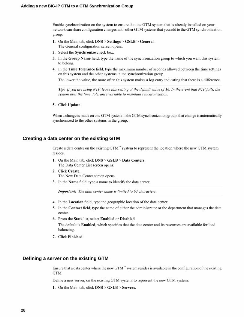
Enable synchronization on the system to ensure that the GTM system that is already installed on yournetwork can share configuration changes with other GTM systems that you add to the GTM synchronizationgroup.
1. On the Main tab, click DNS > Settings > GSLB > General.The General configuration screen opens.
2. Select the Synchronize check box.3. In the Group Name field, type the name of the synchronization group to which you want this system
to belong.4. In the Time Tolerance field, type the maximum number of seconds allowed between the time settings
on this system and the other systems in the synchronization group.The lower the value, the more often this system makes a log entry indicating that there is a difference.
Tip: If you are using NTP, leave this setting at the default value of 10. In the event that NTP fails, thesystem uses the time_tolerance variable to maintain synchronization.
5. Click Update.
When a change is made on one GTM system in the GTM synchronization group, that change is automaticallysynchronized to the other systems in the group.
Creating a data center on the existing GTM
Create a data center on the existing GTM™ system to represent the location where the new GTM systemresides.
1. On the Main tab, click DNS > GSLB > Data Centers.The Data Center List screen opens.
2. Click Create.The New Data Center screen opens.
3. In the Name field, type a name to identify the data center.
Important: The data center name is limited to 63 characters.
4. In the Location field, type the geographic location of the data center.5. In the Contact field, type the name of either the administrator or the department that manages the data
center.6. From the State list, select Enabled or Disabled.
The default is Enabled, which specifies that the data center and its resources are available for loadbalancing.
7. Click Finished.
Defining a server on the existing GTM
Ensure that a data center where the newGTM™ system resides is available in the configuration of the existingGTM.
Define a new server, on the existing GTM system, to represent the new GTM system.
1. On the Main tab, click DNS > GSLB > Servers.
28
Adding a new BIG-IP GTM to a GTM Synchronization Group
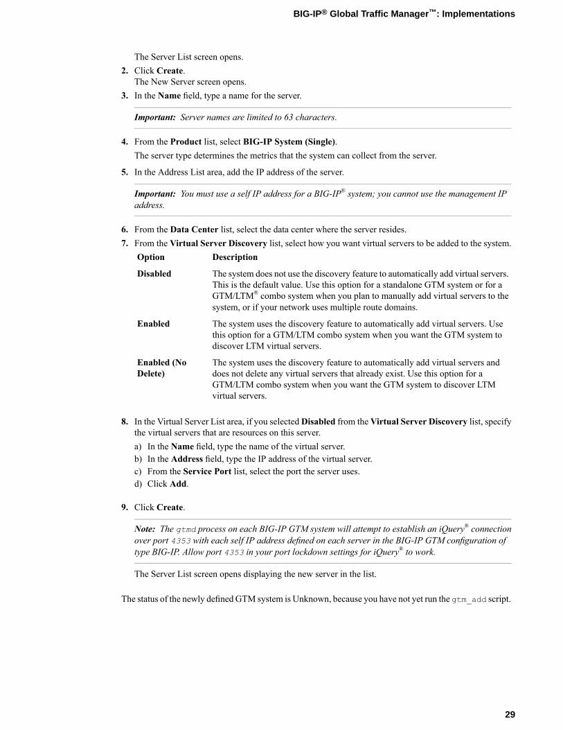
The Server List screen opens.2. Click Create.
The New Server screen opens.3. In the Name field, type a name for the server.
Important: Server names are limited to 63 characters.
4. From the Product list, select BIG-IP System (Single).The server type determines the metrics that the system can collect from the server.
5. In the Address List area, add the IP address of the server.
Important: You must use a self IP address for a BIG-IP® system; you cannot use the management IPaddress.
6. From the Data Center list, select the data center where the server resides.7. From the Virtual Server Discovery list, select how you want virtual servers to be added to the system.
DescriptionOption
The system does not use the discovery feature to automatically add virtual servers.This is the default value. Use this option for a standalone GTM system or for a
Disabled
GTM/LTM® combo system when you plan to manually add virtual servers to thesystem, or if your network uses multiple route domains.
The system uses the discovery feature to automatically add virtual servers. Usethis option for a GTM/LTM combo system when you want the GTM system todiscover LTM virtual servers.
Enabled
The system uses the discovery feature to automatically add virtual servers anddoes not delete any virtual servers that already exist. Use this option for a
Enabled (NoDelete)
GTM/LTM combo system when you want the GTM system to discover LTMvirtual servers.
8. In the Virtual Server List area, if you selectedDisabled from theVirtual Server Discovery list, specifythe virtual servers that are resources on this server.a) In the Name field, type the name of the virtual server.b) In the Address field, type the IP address of the virtual server.c) From the Service Port list, select the port the server uses.d) Click Add.
9. Click Create.
Note: The gtmd process on each BIG-IP GTM system will attempt to establish an iQuery® connectionover port 4353 with each self IP address defined on each server in the BIG-IP GTM configuration oftype BIG-IP. Allow port 4353 in your port lockdown settings for iQuery® to work.
The Server List screen opens displaying the new server in the list.
The status of the newly defined GTM system is Unknown, because you have not yet run the gtm_add script.
29
BIG-IP® Global Traffic Manager™: Implementations
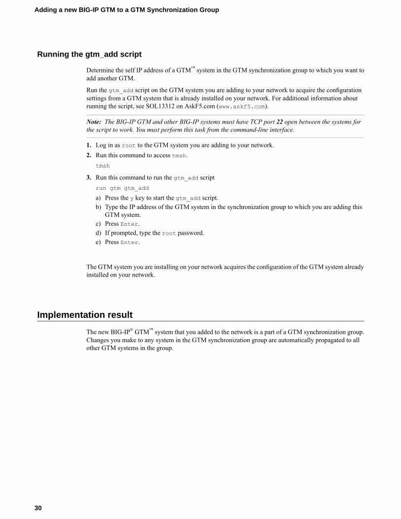
Running the gtm_add script
Determine the self IP address of a GTM™ system in the GTM synchronization group to which you want toadd another GTM.
Run the gtm_add script on the GTM system you are adding to your network to acquire the configurationsettings from a GTM system that is already installed on your network. For additional information aboutrunning the script, see SOL13312 on AskF5.com (www.askf5.com).
Note: The BIG-IP GTM and other BIG-IP systems must have TCP port 22 open between the systems forthe script to work. You must perform this task from the command-line interface.
1. Log in as root to the GTM system you are adding to your network.2. Run this command to access tmsh.
tmsh
3. Run this command to run the gtm_add scriptrun gtm gtm_add
a) Press the y key to start the gtm_add script.b) Type the IP address of the GTM system in the synchronization group to which you are adding this
GTM system.c) Press Enter.d) If prompted, type the root password.e) Press Enter.
The GTM system you are installing on your network acquires the configuration of the GTM system alreadyinstalled on your network.
Implementation result
The new BIG-IP® GTM™ system that you added to the network is a part of a GTM synchronization group.Changes you make to any system in the GTM synchronization group are automatically propagated to allother GTM systems in the group.
30
Adding a new BIG-IP GTM to a GTM Synchronization Group
Delegating DNS Traffic to BIG-IP GTM
Overview: Delegating DNS traffic to wide IPs on BIG-IP GTM
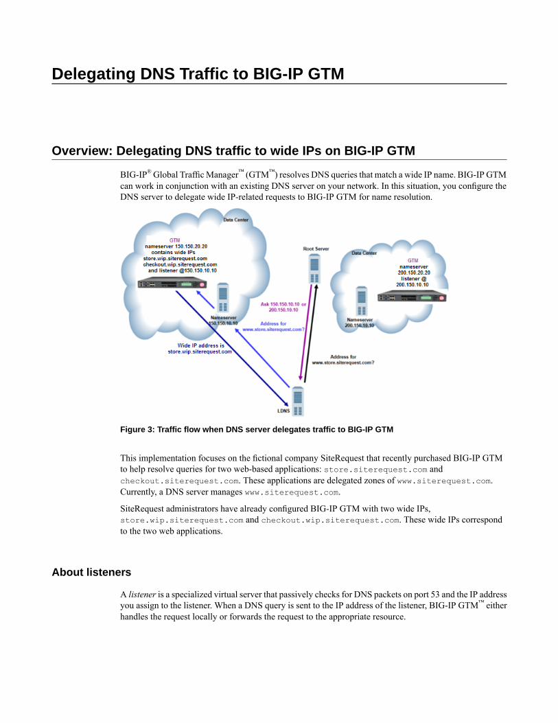
BIG-IP®Global TrafficManager™ (GTM™) resolves DNS queries that match a wide IP name. BIG-IP GTMcan work in conjunction with an existing DNS server on your network. In this situation, you configure theDNS server to delegate wide IP-related requests to BIG-IP GTM for name resolution.
Figure 3: Traffic flow when DNS server delegates traffic to BIG-IP GTM
This implementation focuses on the fictional company SiteRequest that recently purchased BIG-IP GTMto help resolve queries for two web-based applications: store.siterequest.com andcheckout.siterequest.com. These applications are delegated zones of www.siterequest.com.Currently, a DNS server manages www.siterequest.com.
SiteRequest administrators have already configured BIG-IP GTM with two wide IPs,store.wip.siterequest.com and checkout.wip.siterequest.com. These wide IPs correspondto the two web applications.
About listeners
A listener is a specialized virtual server that passively checks for DNS packets on port 53 and the IP addressyou assign to the listener. When a DNS query is sent to the IP address of the listener, BIG-IP GTM™ eitherhandles the request locally or forwards the request to the appropriate resource.
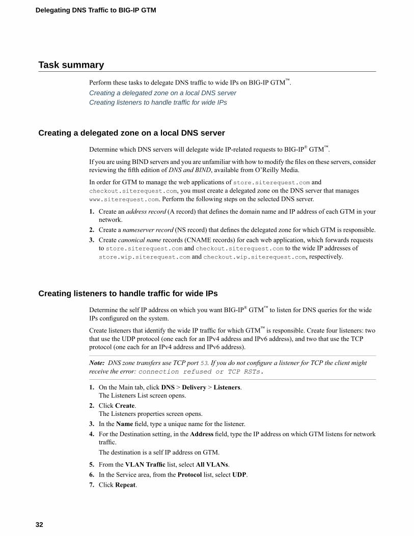
Task summary
Perform these tasks to delegate DNS traffic to wide IPs on BIG-IP GTM™.Creating a delegated zone on a local DNS serverCreating listeners to handle traffic for wide IPs
Creating a delegated zone on a local DNS server
Determine which DNS servers will delegate wide IP-related requests to BIG-IP® GTM™.
If you are using BIND servers and you are unfamiliar with how to modify the files on these servers, considerreviewing the fifth edition of DNS and BIND, available from O’Reilly Media.
In order for GTM to manage the web applications of store.siterequest.com andcheckout.siterequest.com, you must create a delegated zone on the DNS server that manageswww.siterequest.com. Perform the following steps on the selected DNS server.
1. Create an address record (A record) that defines the domain name and IP address of each GTM in yournetwork.
2. Create a nameserver record (NS record) that defines the delegated zone for which GTM is responsible.3. Create canonical name records (CNAME records) for each web application, which forwards requests
to store.siterequest.com and checkout.siterequest.com to the wide IP addresses ofstore.wip.siterequest.com and checkout.wip.siterequest.com, respectively.
Creating listeners to handle traffic for wide IPs
Determine the self IP address on which you want BIG-IP® GTM™ to listen for DNS queries for the wideIPs configured on the system.
Create listeners that identify the wide IP traffic for which GTM™ is responsible. Create four listeners: twothat use the UDP protocol (one each for an IPv4 address and IPv6 address), and two that use the TCPprotocol (one each for an IPv4 address and IPv6 address).
Note: DNS zone transfers use TCP port 53. If you do not configure a listener for TCP the client mightreceive the error: connection refused or TCP RSTs.
1. On the Main tab, click DNS > Delivery > Listeners.The Listeners List screen opens.
2. Click Create.The Listeners properties screen opens.
3. In the Name field, type a unique name for the listener.4. For the Destination setting, in the Address field, type the IP address on which GTM listens for network
traffic.The destination is a self IP address on GTM.
5. From the VLAN Traffic list, select All VLANs.6. In the Service area, from the Protocol list, select UDP.7. Click Repeat.
32
Delegating DNS Traffic to BIG-IP GTM

Create another listener with the same IPv4 address and configuration, but select TCP from the Protocollist. Then, create two more listeners, configuring both with the same IPv6 address, but one with the UDPprotocol and one with the TCP protocol.
Implementation result
You now have an implementation of BIG-IP® GTM™ in which the DNS server manages DNS traffic unlessthe query is for store.sitrequest.com or checkout.siterequest.com. When the DNS serverreceives these queries, it delegates them to BIG-IP GTM, which then load balances the queries to theappropriate wide IPs.
33
BIG-IP® Global Traffic Manager™: Implementations

Redirecting DNS Queries Using a CNAME Record
Overview: Redirecting DNS queries using a CNAME record
When you want to redirect DNS queries for a web site to a different web site, create a wide IP that representsthe original web site, and add a pool configured with a CNAME to the wide IP to redirect the requests tothe new destination.
The executives at siterequest.com recently purchased a competitor. Site Request's administrator wantsto redirect DNS queries for competitor.com to a rebranded web site namedcompetitor.siterequest.com.
About CNAME records
A CNAME record specifies that a domain name is an alias of another domain. When you create a pool witha canonical name, BIG-IP® Global Traffic Manager™(GTM™) responds to DNS name resolution requestsfor the CNAME with the real fully qualified domain name (FQDN).
Task summary
Perform these tasks to redirect a DNS request using a wide IP, which includes a pool that is configured witha CNAME.Creating a pool using a CNAMECreating a wide IP with a CNAME poolViewing statistics for wide IP CNAME resolutions
Creating a pool using a CNAME
Create a pool to which the system can load balance DNS queries using a CNAME record, rather than poolmembers. For example, you can name the pool competitor_redirect and use a CNAME ofcompetitor.siterequest.com.
1. On the Main tab, click DNS > GSLB > Pools.The Pools list screen opens.
2. Click Create.3. In the Name field, type a name for the pool.
Names must begin with a letter, and can contain only letters, numbers, and the underscore (_) character.
Important: The pool name is limited to 63 characters.

4. From the Configuration list, select Advanced.5. In the CNAME field, type the canonical name of the zone to which you want GTM™ to send DNS
queries.
Tip: When you provide a canonical name, you do not add members to the pool, because the CNAMErecord always takes precedence over pool members. Additionally, a pool with a CNAME is not monitoredfor availability.
6. Click Finished.
Creating a wide IP with a CNAME pool
Ensure that a pool configured with a CNAME exists in the BIG-IP® configuration.
Create a wide IP that includes a pool configured with a CNAME to redirect DNS queries for a web site, toa different web site.
1. On the Main tab, click DNS > GSLB >Wide IPs.The Wide IP List screen opens.
2. Click Create.The New Wide IP screen opens.
3. In the Name field, type a name for the wide IP.
Tip: You can use two different wildcard characters in the wide IP name: asterisk (*) to represent severalcharacters and question mark (?) to represent a single character. This reduces the number of aliasesyou have to add to the configuration.
4. From the Pool list, select the CNAME pool, and then click Add.5. Click Finished.
Viewing statistics for wide IP CNAME resolutions
Ensure that a wide IP that includes a pool configured with a CNAME exists in the BIG-IP® configuration.
You can view the number of DNS queries that GTM™ resolved using a CNAME record.
1. On the Main tab, click Statistics >Module Statistics > DNS > GSLB.The Global Traffic statistics screen opens.
2. From the Statistics Type list, selectWide IPs.Information displays about the cumulative number of DNS name resolution requests processed by thewide IP, and the number of requests load balanced using specific methods.
Implementation result
You now have an implementation in which BIG-IP®GTM™ resolves a DNS query for a wide IP to a CNAME.The LDNS must further resolve the CNAME to an IP address.
36
Redirecting DNS Queries Using a CNAME Record
Replacing a DNS Server with BIG-IP GTM
Overview: Replacing a DNS server with BIG-IP GTM
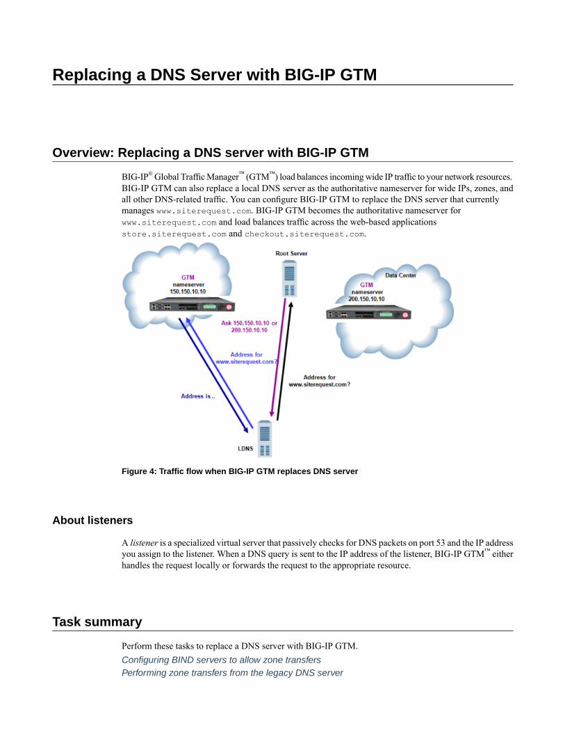
BIG-IP®Global TrafficManager™ (GTM™) load balances incomingwide IP traffic to your network resources.BIG-IP GTM can also replace a local DNS server as the authoritative nameserver for wide IPs, zones, andall other DNS-related traffic. You can configure BIG-IP GTM to replace the DNS server that currentlymanages www.siterequest.com. BIG-IP GTM becomes the authoritative nameserver forwww.siterequest.com and load balances traffic across the web-based applicationsstore.siterequest.com and checkout.siterequest.com.
Figure 4: Traffic flow when BIG-IP GTM replaces DNS server
About listeners
A listener is a specialized virtual server that passively checks for DNS packets on port 53 and the IP addressyou assign to the listener. When a DNS query is sent to the IP address of the listener, BIG-IP GTM™ eitherhandles the request locally or forwards the request to the appropriate resource.
Task summary
Perform these tasks to replace a DNS server with BIG-IP GTM.Configuring BIND servers to allow zone transfersPerforming zone transfers from the legacy DNS server
Creating a self IP address using the IP address of the legacy DNS serverDesignating GTM as the primary server for the zoneCreating listeners to alert GTM to DNS traffic destined for the systemCreating a wide IP
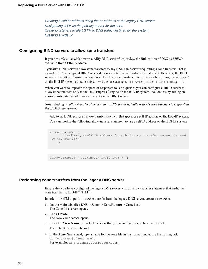
Configuring BIND servers to allow zone transfers
If you are unfamiliar with how to modify DNS server files, review the fifth edition of DNS and BIND,available from O’Reilly Media.
Typically, BIND servers allow zone transfers to any DNS nameserver requesting a zone transfer. That is,named.conf on a typical BIND server does not contain an allow-transfer statement. However, the BINDserver on the BIG-IP® system is configured to allow zone transfers to only the localhost. Thus, named.confon the BIG-IP system contains this allow-transfer statement: allow-transfer { localhost; } ;.
When you want to improve the speed of responses to DNS queries you can configure a BIND server toallow zone transfers only to the DNS Express™ engine on the BIG-IP system. You do this by adding anallow-transfer statement to named.conf on the BIND server.
Note: Adding an allow-transfer statement to a BIND server actually restricts zone transfers to a specifiedlist of DNS nameservers.
Add to the BIND server an allow-transfer statement that specifies a self IP address on the BIG-IP system.You can modify the following allow-transfer statement to use a self IP address on the BIG-IP system:
allow-transfer {localhost; <self IP address from which zone transfer request is sent
to the server>;};
allow-transfer { localhost; 10.10.10.1 ; };
Performing zone transfers from the legacy DNS server
Ensure that you have configured the legacy DNS server with an allow-transfer statement that authorizeszone transfers to BIG-IP® GTM™.
In order for GTM to perform a zone transfer from the legacy DNS server, create a new zone.
1. On the Main tab, click DNS > Zones > ZoneRunner > Zone List.The Zone List screen opens.
2. Click Create.The New Zone screen opens.
3. From the View Name list, select the view that you want this zone to be a member of.The default view is external.
4. In the Zone Name field, type a name for the zone file in this format, including the trailing dot:db.[viewname].[zonename].For example, db.external.siterequest.com.
38
Replacing a DNS Server with BIG-IP GTM
5. From the Zone Type list, selectMaster.6. From the Records Creation Method list, select Transfer from Server.7. In the Records Creation area, type the values for the SOA and NS record parameters.8. Click Finished.
Creating a self IP address using the IP address of the legacy DNS server
To avoid a conflict on your network, unplug BIG-IP® GTM™ from the network.
When you want GTM to handle DNS traffic previously handled by a DNS server, create a self IP addresson GTM using the IP address of the legacy DNS server.
1. On the Main tab, click Network > Self IPs.2. Click Create.
The New Self IP screen opens.3. In the Name field, type a unique name for the self IP address.4. In the IP Address field, type the IP address of the legacy DNS server.
The system accepts IPv4 and IPv6 addresses.
5. In the Netmask field, type the full network mask for the specified IP address.
For example, you can type ffff:ffff:ffff:ffff:0000:0000:0000:0000 orffff:ffff:ffff:ffff::.
6. Click Finished.The screen refreshes, and displays the new self IP address.
Designating GTM as the primary server for the zone
Ensure that you have created a self IP address on BIG-IP® GTM™ using the IP address of the legacy DNSserver.
Add this self IP address to the GTM server object, and then modify the DNS server based on your networkconfiguration.
1. On the Main tab, click DNS > GSLB > Servers.The Server List screen opens.
2. Click the name of the GTM system that you want to modify.The server settings and values display.
3. In the Address List area, add the new self IP address.4. Click Update.5. Do one of the following based on your network configuration:
• Modify the IP address of the legacy DNS server so that it becomes a secondary DNS server to BIG-IPGTM. Ensure that the IP address of the DNS server does not conflict with the self IP address thatyou added to the BIG-IP GTM server object.
Note: If you are using BIND servers, and you are unfamiliar with how to change a DNS server froma primary to a secondary, refer to the fifth edition of DNS and BIND, available from O’Reilly Media.
• Remove the legacy DNS server from your network.
39
BIG-IP® Global Traffic Manager™: Implementations
BIG-IP GTM is now the primary authoritative name server for the zone. The servers for the zone do notneed to be updated, because the IP address of the legacy DNS server was assigned to BIG-IP GTM.
Creating listeners to alert GTM to DNS traffic destined for the system
To alert the BIG-IP® GTM™ system to DNS queries (previously handled by the DNS server), create fourlisteners: two that use the UDP protocol (one each for an IPv4 address and IPv6 address), and two that usethe TCP protocol (one each for an IPv4 address and IPv6 address).
Note: DNS zone transfers use TCP port 53. If you do not configure a listener for TCP the client mightreceive the error: connection refused or TCP RSTs.
1. On the Main tab, click DNS > Delivery > Listeners.The Listeners List screen opens.
2. Click Create.The Listeners properties screen opens.
3. In the Name field, type a unique name for the listener.4. For the Destination setting, in theAddress field, type the IP address previously used by the legacy DNS
server.5. From the VLAN Traffic list, select All VLANs.6. In the Service area, from the Protocol list, select UDP.7. Click Finished.
Create another listener with the same IPv4 address and configuration, but select TCP from the Protocollist. Then, create two more listeners, configuring both with the same IPv6 address, but one with the UDPprotocol and one with the TCP protocol.
Creating a wide IP
Ensure that at least one load balancing pool exists in the configuration before you start creating a wide IP.
Create a wide IP to map a FQDN to one or more pools of virtual servers that host the content of the domain.
1. On the Main tab, click DNS > GSLB >Wide IPs.The Wide IP List screen opens.
2. Click Create.The New Wide IP screen opens.
3. In the Name field, type a name for the wide IP.
Tip: You can use two different wildcard characters in the wide IP name: asterisk (*) to represent severalcharacters and question mark (?) to represent a single character. This reduces the number of aliasesyou have to add to the configuration.
4. From the Pool list, select the pools that this wide IP uses for load balancing.The system evaluates the pools based on the wide IP load balancing method configured.a) From the Pool list, select a pool.
A pool can belong to more than one wide IP.b) Click Add.
40
Replacing a DNS Server with BIG-IP GTM

5. Click Finished.
Implementation result
BIG-IP® GTM™ replaces the legacy DNS server as the primary authoritative name server for the zone.BIG-IP GTM handles all incoming DNS traffic, whether destined for a wide IP or handled by the BINDinstance on the system.
41
BIG-IP® Global Traffic Manager™: Implementations

Placing BIG-IP GTM in Front of a DNS Server
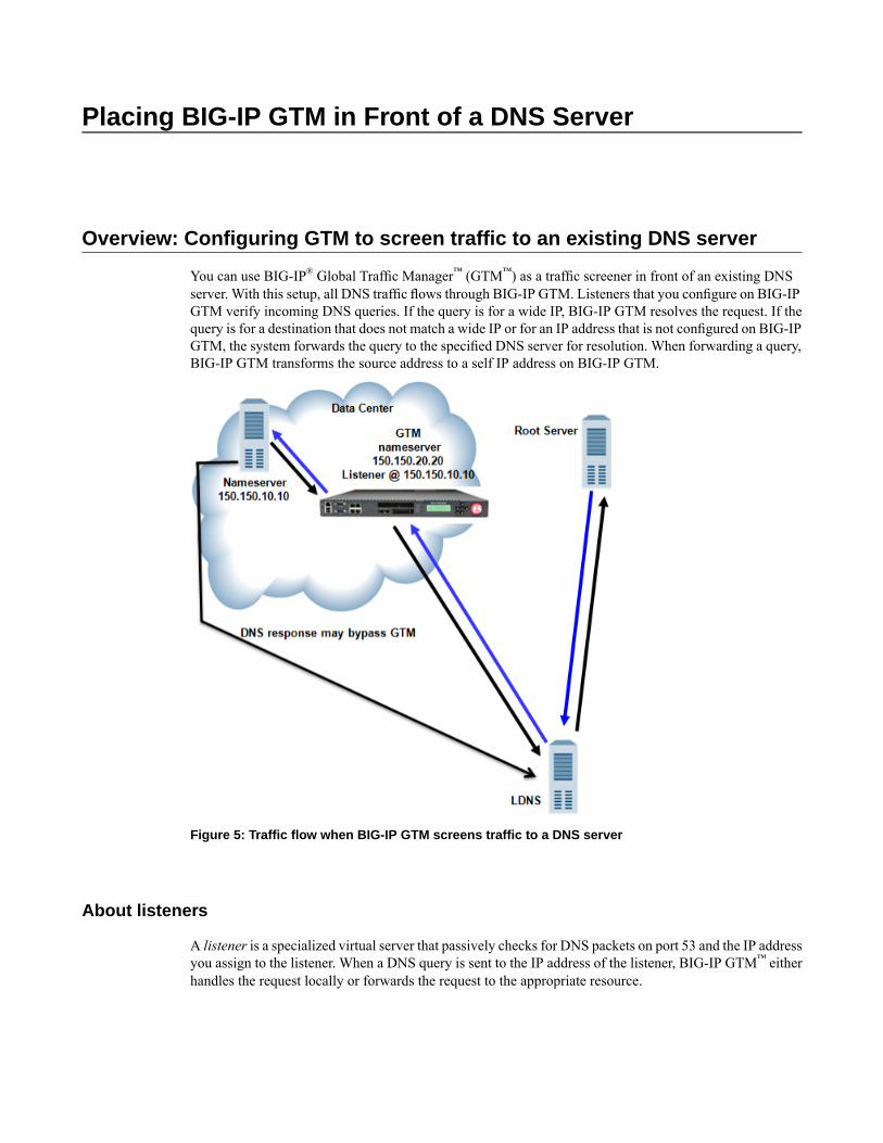
Overview: Configuring GTM to screen traffic to an existing DNS server
You can use BIG-IP® Global Traffic Manager™ (GTM™) as a traffic screener in front of an existing DNSserver. With this setup, all DNS traffic flows through BIG-IP GTM. Listeners that you configure on BIG-IPGTM verify incoming DNS queries. If the query is for a wide IP, BIG-IP GTM resolves the request. If thequery is for a destination that does not match a wide IP or for an IP address that is not configured on BIG-IPGTM, the system forwards the query to the specified DNS server for resolution. When forwarding a query,BIG-IP GTM transforms the source address to a self IP address on BIG-IP GTM.
Figure 5: Traffic flow when BIG-IP GTM screens traffic to a DNS server
About listeners
A listener is a specialized virtual server that passively checks for DNS packets on port 53 and the IP addressyou assign to the listener. When a DNS query is sent to the IP address of the listener, BIG-IP GTM™ eitherhandles the request locally or forwards the request to the appropriate resource.
About wildcard listeners
A wildcard listener is a special listener that is assigned an IP address of 0.0.0.0 and the DNS query port(port 53). When you want BIG-IP®GTM™ to respond to DNS queries coming into your network, regardlessof the destination IP address of the given request, you use a wildcard listener.
Task summary
Perform these tasks to send traffic through BIG-IP® GTM™.Placing BIG-IP GTM on your network to forward trafficCreating listeners to forward traffic to a DNS serverCreating a wide IP
Placing BIG-IP GTM on your network to forward traffic
Determine to which DNS server you want BIG-IP® GTM™ to forward traffic.
Place GTM on your network between LDNS servers and clients making DNS name resolution requests.
1. Physically connect GTM to your Internet connection.2. Connect the LDNS to an Ethernet port on GTM (optional).3. Connect the LDNS to a switch.
Creating listeners to forward traffic to a DNS server
Determine to which DNS server you want the listeners to forward DNS queries.
Create listeners to alert the BIG-IP system to queries destined for a DNS server. Create four wildcardlisteners: two that use the UDP protocol (one each for an IPv4 address and IPv6 address), and two that usethe TCP protocol (one each for an IPv4 address and IPv6 address).
Note: DNS zone transfers use TCP port 53. If you do not configure a listener for TCP the client mightreceive the error: connection refused or TCP RSTs.
1. On the Main tab, click DNS > Delivery > Listeners.The Listeners List screen opens.
2. Click Create.The Listeners properties screen opens.
3. In the Name field, type a unique name for the listener.4. For the Destination setting, in the Address field, type the IP address on which GTM listens for DNS
queries.The destination is the IP address of a DNS server to which you want the listeners to route DNS queries.
Important: The destination must not match a self IP address on GTM.
44
Placing BIG-IP GTM in Front of a DNS Server
5. From the VLAN Traffic list, select All VLANs.6. In the Service area, from the Protocol list, select UDP.7. Click Finished.
Create another listener with the same IPv4 address and configuration, but select TCP from the Protocollist. Then, create two more listeners, configuring both with the same IPv6 address, but one with the UDPprotocol and one with the TCP protocol.
Creating a wide IP
Ensure that at least one load balancing pool exists in the configuration before you start creating a wide IP.
Create a wide IP to map a FQDN to one or more pools of virtual servers that host the content of the domain.
1. On the Main tab, click DNS > GSLB >Wide IPs.The Wide IP List screen opens.
2. Click Create.The New Wide IP screen opens.
3. In the Name field, type a name for the wide IP.
Tip: You can use two different wildcard characters in the wide IP name: asterisk (*) to represent severalcharacters and question mark (?) to represent a single character. This reduces the number of aliasesyou have to add to the configuration.
4. From the Pool list, select the pools that this wide IP uses for load balancing.The system evaluates the pools based on the wide IP load balancing method configured.a) From the Pool list, select a pool.
A pool can belong to more than one wide IP.b) Click Add.
5. Click Finished.
Implementation result
You now have an implementation in which BIG-IP®GTM™ receives all DNS queries. If the query is for awide IP, BIG-IP GTM load balances the request to the appropriate resource. If the query is for an IP addressof a DNS server, BIG-IP GTM either routes or forwards the query to the DNS server for resolution.
45
BIG-IP® Global Traffic Manager™: Implementations

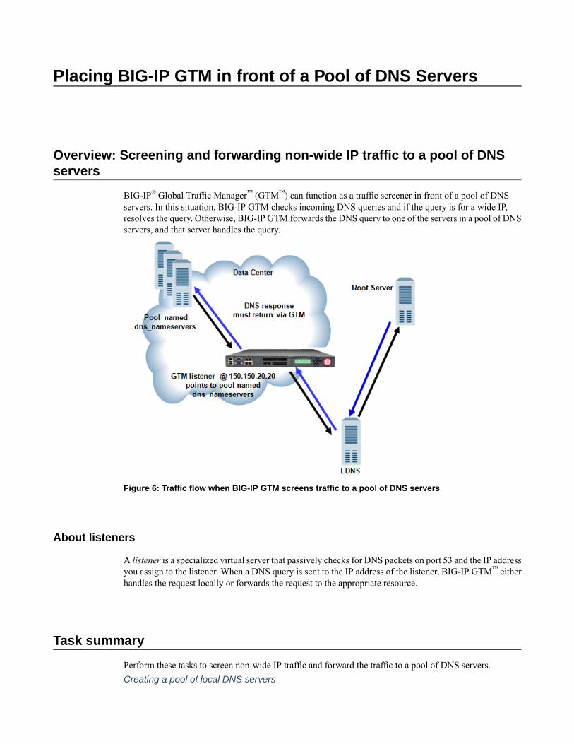
Placing BIG-IP GTM in front of a Pool of DNS Servers
Overview: Screening and forwarding non-wide IP traffic to a pool of DNSservers
BIG-IP® Global Traffic Manager™ (GTM™) can function as a traffic screener in front of a pool of DNSservers. In this situation, BIG-IP GTM checks incoming DNS queries and if the query is for a wide IP,resolves the query. Otherwise, BIG-IP GTM forwards the DNS query to one of the servers in a pool of DNSservers, and that server handles the query.
Figure 6: Traffic flow when BIG-IP GTM screens traffic to a pool of DNS servers
About listeners
A listener is a specialized virtual server that passively checks for DNS packets on port 53 and the IP addressyou assign to the listener. When a DNS query is sent to the IP address of the listener, BIG-IP GTM™ eitherhandles the request locally or forwards the request to the appropriate resource.
Task summary
Perform these tasks to screen non-wide IP traffic and forward the traffic to a pool of DNS servers.Creating a pool of local DNS servers
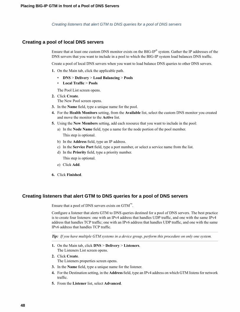
Creating listeners that alert GTM to DNS queries for a pool of DNS servers
Creating a pool of local DNS servers
Ensure that at least one custom DNS monitor exists on the BIG-IP® system. Gather the IP addresses of theDNS servers that you want to include in a pool to which the BIG-IP system load balances DNS traffic.
Create a pool of local DNS servers when you want to load balance DNS queries to other DNS servers.
1. On the Main tab, click the applicable path.
• DNS > Delivery > Load Balancing > Pools• Local Traffic > Pools
The Pool List screen opens.2. Click Create.
The New Pool screen opens.3. In the Name field, type a unique name for the pool.4. For the Health Monitors setting, from the Available list, select the custom DNS monitor you created
and move the monitor to the Active list.5. Using the New Members setting, add each resource that you want to include in the pool:
a) In the Node Name field, type a name for the node portion of the pool member.This step is optional.
b) In the Address field, type an IP address.c) In the Service Port field, type a port number, or select a service name from the list.d) In the Priority field, type a priority number.
This step is optional.e) Click Add.
6. Click Finished.
Creating listeners that alert GTM to DNS queries for a pool of DNS servers
Ensure that a pool of DNS servers exists on GTM™.
Configure a listener that alerts GTM to DNS queries destined for a pool of DNS servers. The best practiceis to create four listeners: one with an IPv4 address that handles UDP traffic, and one with the same IPv4address that handles TCP traffic; one with an IPv6 address that handles UDP traffic, and one with the sameIPv6 address that handles TCP traffic.
Tip: If you have multiple GTM systems in a device group, perform this procedure on only one system.
1. On the Main tab, click DNS > Delivery > Listeners.The Listeners List screen opens.
2. Click Create.The Listeners properties screen opens.
3. In the Name field, type a unique name for the listener.4. For the Destination setting, in theAddress field, type an IPv4 address on which GTM listens for network
traffic.5. From the Listener list, select Advanced.
48
Placing BIG-IP GTM in front of a Pool of DNS Servers

6. For the Address Translation setting, select the Enabled check box.7. In the Service area, from the Protocol list, select UDP.8. From the Default Pool list, select the pool to which this listener forwards DNS queries.9. Click Finished.
Create another listener with the same IPv4 address and configuration, but select TCP from the Protocollist. Then, create two more listeners, configuring both with the same IPv6 address, but one with the UDPprotocol and one with the TCP protocol.
Implementation result
You now have an implementation in which BIG-IP®GTM™ receives DNS queries, handles wide IP requests,and forwards all other DNS queries to members of the pool of DNS servers.
49
BIG-IP® Global Traffic Manager™: Implementations

Configuring GTM to Determine PGW Health and Availability
Overview: Configuring GTM to determine packet gateway health andavailability
Service providers can configure the BIG-IP® GTM™ system to increase the availability of their customerservices on the System Architecture Evolution (SAE) network. One way is to configure a GTP monitor forthe health and availability of a packet gateway (PGW). The GTP monitor issues an echo request to a list ofPGW systems. If a PGW fails to respond to the GTP echo request, it is marked as down, and removed fromthe list of available PGW systems that are returned to an MME in a DNS response. GTM can also beconfigured to load balance DNS queries for the access point name (APN) across the PGW systems that areactive and available.
Note: GTM handles only A and AAAA records for global server load balancing (GSLB).
This illustration presents a simplified depiction of how the process works on the SAE network.
Figure 7: GTM monitoring packet gateways
1. A smartphone that is preprogrammed with an APN, for example, apn.servprov.com, initiates a dataconnection.
2. The EPC MME performs a DNS lookup on apn.servprov.com in order to select a packet gateway.3. GTM handles the DNS request and returns only IP addresses for PGW systems that are active and
available.
Task summaryConfigure GTM using these tasks to determine PGW system health and availability, and to load balanceDNS queries across the active and available PGW systems.
Important: Before you perform these tasks, ensure that the BIG-IP system is in the PGW trust list.
Defining a data centerDefining BIG-IP GTM systemsDefining packet gateway systemsCreating listeners to identify DNS traffic for an APNCreating a custom GTP monitorCreating a pool of packet gateway systemsConfiguring a wide IP for load balancing APN lookups
Defining a data center
On BIG-IP®GTM™, create a data center to contain the servers that reside on a subnet of your network.
1. On the Main tab, click DNS > GSLB > Data Centers.The Data Center List screen opens.
2. Click Create.The New Data Center screen opens.
3. In the Name field, type a name to identify the data center.
Important: The data center name is limited to 63 characters.
4. In the Location field, type the geographic location of the data center.5. In the Contact field, type the name of either the administrator or the department that manages the data
center.6. From the State list, select Enabled.7. Click Finished.
Now you can create server objects and assign them to this data center.
Repeat these steps to create additional data centers.
Defining BIG-IP GTM systems
Ensure that at least one data center exists in the configuration before you start creating a server.
On BIG-IP® GTM™, create a server object to represent the GTM system itself.
1. On the Main tab, click DNS > GSLB > Servers.The Server List screen opens.
2. Click Create.The New Server screen opens.
3. In the Name field, type a name for the server.
Important: Server names are limited to 63 characters.
4. From the Product list, select BIG-IP System (Single).The server type determines the metrics that the system can collect from the server.
5. In the Address List area, add the non-floating IP addresses of the server.
52
Configuring GTM to Determine PGW Health and Availability

You can add more than one IP address, depending on how the server interacts with the rest of yournetwork.
Important: You must use a self IP address for a BIG-IP system; you cannot use the management IPaddress.
6. From the Data Center list, select the data center where the server resides.7. In the Health Monitors area, assign the bigipmonitor to the server by moving it from the Available list
to the Selected list.8. From the Virtual Server Discovery list, select how you want virtual servers to be added to the system.
DescriptionOption
The system does not use the discovery feature to automatically add virtual servers.This is the default value. Use this option for a standalone GTM system or for a
Disabled
GTM/LTM® combo system when you plan to manually add virtual servers to thesystem, or if your network uses multiple route domains.
The system uses the discovery feature to automatically add virtual servers. Usethis option for a GTM/LTM combo system when you want the GTM system todiscover LTM virtual servers.
Enabled
The system uses the discovery feature to automatically add virtual servers anddoes not delete any virtual servers that already exist. Use this option for a
Enabled (NoDelete)
GTM/LTM combo system when you want the GTM system to discover LTMvirtual servers.
9. In the Virtual Server List area, if you selectedDisabled from theVirtual Server Discovery list, specifythe virtual servers that are resources on this server.a) In the Name field, type the name of the virtual server.b) In the Address field, type the IP address of the virtual server.c) From the Service Port list, select the port the server uses.d) Click Add.
10. From the Link Discovery list, select how you want links to be added to the system.DescriptionOption
The system does not use the discovery feature to automatically add links. Thisis the default value. Use this option for a standalone GTM system or for aGTM/LTM combo system when you plan to manually add links to the system.
Disabled
The system uses the discovery feature to automatically add links. Use this optionfor a GTM/LTM combo system when you want BIG-IP GTM to discover links.
Enabled
The system uses the discovery feature to automatically add links and does notdelete any links that already exist. Use this option for a GTM/LTM combo systemwhen you want GTM to discover links.
Enabled (NoDelete)
11. Click Create.The Server List screen opens displaying the new server in the list.
Defining packet gateway systems
Before you create servers to represent the packet gateway (PGW) systems, ensure there is an existing serverin the BIG-IP® GTM™ system that you are configuring.
53
BIG-IP® Global Traffic Manager™: Implementations
Define the PGW systems to which BIG-IP GTM load balances access point name (APN) traffic.
1. On the Main tab, click DNS > GSLB > Servers.The Server List screen opens.
2. Click Create.The New Server screen opens.
3. In the Name field, type a name for the server.
Important: Server names are limited to 63 characters.
4. From the Product list, select Generic Host.The server type determines the metrics that the system can collect from the server.
5. In the Address List area, add the IP addresses of the PGW system.a) Type an external (public) IP address in the Address field, and then click Add.b) If you use NAT, type an internal (private) IP address in the Translation field, and then click Add.
You can add more than one IP address, depending on how the PGW system interacts with the rest ofyour network.
6. From the Data Center list, select the data center where the server resides.7. In the HealthMonitors area, you can assign the GTPmonitor to the server bymoving it from theAvailable
list to the Selected list; however, best practice is to assign theGTPmonitor to the pool of PGW systems.
Tip: The GTP monitor simply checks that the PGW system responds to a GTP echo request.
8. In the Virtual Server List area, if you selected Disabled from the Virtual Server Discovery list, createa virtual server to represent (in a pool) the PGW system.a) In the Name field, type a name for the virtual server.b) In the Address field, type the IP address of the host server.c) In the Service Port field, type 2152 (F5 Networks recommends using this GTP-user plane tunneling
data port); however, the BIG-IP system also supports the use of 2123 (GTP-control plane port).d) Click Add.
9. Click Create.The Server List screen opens displaying the new server in the list.
Define the other PGW systems on your network.
Creating listeners to identify DNS traffic for an APN
Ensure that a self IP address exists on BIG-IP® GTM™ that you can use as the Destination of the listener.
Create listeners to identify DNS traffic for a specific access point name (APN). The best practice is to createtwo listeners: one that handles UDP traffic and one that handles TCP traffic.
1. On the Main tab, click DNS > Delivery > Listeners.The Listeners List screen opens.
2. Click Create.The Listeners properties screen opens.
3. In the Name field, type a unique name for the listener.4. For the Destination setting, in the Address field, type the IP address on which GTM listens for access
point name (APN) traffic.
54
Configuring GTM to Determine PGW Health and Availability

Note: F5 Networks recommends that you assign a unique IP address, not a self IP address.
5. In the Service area, from the Protocol list, select UDP.6. Click Finished.
Create another listener with the same IP address, but select TCP from the Protocol list.
Creating a custom GTP monitor
Ensure that you know the version of the GTP protocol that your network uses.
Create a custom GTP monitor to detect the presence and health of a packet gateway (PGW) system. TheGTP monitor issues a GTP echo request, and if the PGW system fails to respond, it is automatically markedas down and removed from the available list of PGW systems that the BIG-IP® system returns to an MME.
1. On the Main tab, click DNS > GSLB >Monitors.The Monitor List screen opens.
2. Click Create.The New Monitor screen opens.
3. Type a name for the monitor in the Name field.4. From the Type list, select GTP.5. From the Import Monitor list, select an existing monitor.
The new monitor inherits initial configuration values from the existing monitor.
6. Type a number in the Interval field that indicates, in seconds, how frequently the system issues themonitor check. The default is 30 seconds.The frequency of a monitor check must be greater than the value of the global-levelHeartbeat Intervalsetting. Otherwise, the monitor can acquire out-of-date data.
7. Type a number in the Timeout field that indicates, in seconds, how much time the target has to respondto the monitor check. The default is 120 seconds.If the target responds within the allotted time period, it is considered up. If the target does not respondwithin the time period, it is considered down.
8. Type a number in the Probe Interval field that indicates the number of seconds between the probessent by the system. The default is 1 second.
9. Type a number in the Probe Timeout field that indicates the number of seconds after which the systemtimes out the probe request to the system. The default is 5 seconds.
10. Type a number in the Probe Attempts field that indicates the number of probes the system sends beforemarking the resource down. The default is 3 attempts.
11. Type a number in the Protocol Version field that indicates the version of the GTP protocol the systemuses. The default is 1.
12. For the Ignore Down Response setting, do one of the following:
• Accept the No default option.• Select the Yes option to specify that the monitor accepts more than one probe attempt per interval.
13. Click Finished.
Now you can associate the new custom monitor with the pool that contains the GTP resources.
Tip: Associate the monitor only with the pool. If you associate the monitor with both the pool and a server,you might encounter inaccurate health check failures.
55
BIG-IP® Global Traffic Manager™: Implementations
Creating a pool of packet gateway systems
Before you can create a pool of packet gateway (PGW) systems, you need to:
• Create servers to represent the PGW systems, and manually add at least one virtual server to each server.• Create a GTP monitor.
When you create a pool of one or more PGW systems it is the best practice to apply the GTP monitor andthe round robin load-balancing method to the pool; however, the BIG-IP® system supports the use of anystatic load balancing method in this implementation.
1. On the Main tab, click DNS > GSLB > Pools.The Pools list screen opens.
2. Click Create.3. In the Name field, type a name for the pool.
Names must begin with a letter, and can contain only letters, numbers, and the underscore (_) character.
Important: The pool name is limited to 63 characters.
4. For the Health Monitors setting, in the Available list, select gtp, and click << to move the monitor tothe Active list.
5. In the Load Balancing Method area, from the Preferred list, select Round Robin.
Tip: When deploying this implementation in a lab environment, to determine whether the BIG-IP systemreturns the DNS response that you expect, try selecting the Global Availability method and disablingthe first pool member in the list.
6. In the Load BalancingMethod area, from theAlternate, and Fallback lists, select a static load balancingmethod, based on your network environment. Ensure that you select a load balancing method that doesnot take current server performance or connection load into account.
7. For the Member List setting, add virtual servers as members of this load balancing pool.The system evaluates the virtual servers (pool members) in the order in which they are listed. A virtualserver can belong to more than one pool.a) Select a virtual server from the Virtual Server list.b) Click Add.
8. Click Finished.
Configuring a wide IP for load balancing APN lookups
Before you configure a wide IP for an access point name (APN), ensure that a pool of packet gateway(PGW) systems is available to associate with the wide IP that you are configuring for APN load balancing.
Configure a wide IP to represent the APN for which BIG-IP® GTM™ load balances DNS lookups acrossthe PGW systems on your network.
1. On the Main tab, click DNS > GSLB >Wide IPs.The Wide IP List screen opens.
2. Click Create.The New Wide IP screen opens.
3. In the Name field, type the APN, for example apn.servprov.com.
56
Configuring GTM to Determine PGW Health and Availability

4. From the Load Balancing Method list, select Round Robin.5. From the Pool list, select the pool of PGW systems, and then click Add.6. Click Finished.
57
BIG-IP® Global Traffic Manager™: Implementations

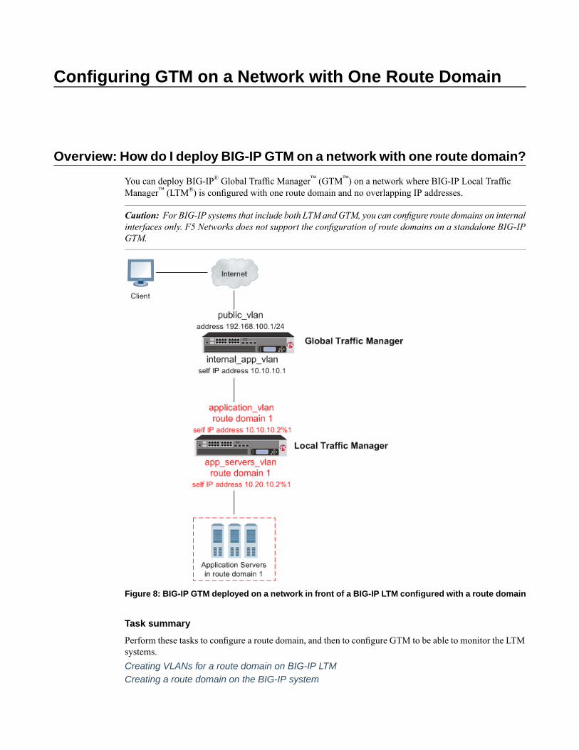
Configuring GTM on a Network with One Route Domain
Overview: How do I deploy BIG-IP GTM on a network with one route domain?
You can deploy BIG-IP® Global Traffic Manager™ (GTM™) on a network where BIG-IP Local TrafficManager™ (LTM®) is configured with one route domain and no overlapping IP addresses.
Caution: For BIG-IP systems that include both LTM and GTM, you can configure route domains on internalinterfaces only. F5 Networks does not support the configuration of route domains on a standalone BIG-IPGTM.
Figure 8: BIG-IP GTM deployed on a network in front of a BIG-IP LTM configured with a route domain
Task summary
Perform these tasks to configure a route domain, and then to configure GTM to be able to monitor the LTMsystems.Creating VLANs for a route domain on BIG-IP LTMCreating a route domain on the BIG-IP system

Creating a self IP address for a route domain on BIG-IP LTMDefining a server for a route domain on BIG-IP GTM
Creating VLANs for a route domain on BIG-IP LTM
You need to create two VLANs on BIG-IP® LTM® through which traffic can pass to a route domain.
1. On the Main tab, click Network > VLANs.The VLAN List screen opens.
2. Click Create.The New VLAN screen opens.
3. In the Name field, type external.4. In the Tag field, type a numeric tag, from 1-4094, for the VLAN, or leave the field blank if you want
the BIG-IP system to automatically assign a VLAN tag.The VLAN tag identifies the traffic from hosts in the associated VLAN.
5. For the Interfaces setting:a) From the Interface list, select an interface number.b) From the Tagging list, select Tagged or Untagged.
Select Tagged when you want traffic for that interface to be tagged with a VLAN ID.c) If you specified a numeric value for theCustomer Tag setting and from theTagging list you selected
Tagged, then from the Tag Mode list, select a value.d) Click Add.e) Repeat these steps for each interface that you want to assign to the VLAN.
6. If you want the system to verify that the return route to an initial packet is the same VLAN from whichthe packet originated, select the Source Check check box.
7. Click Finished.The screen refreshes, and displays the new VLAN in the list.
Repeat this procedure, but in Step 3, name the VLAN internal.
Creating a route domain on the BIG-IP system
Before you create a route domain:
• Ensure that an external and an internal VLAN exist on the BIG-IP® system.• If you intend to assign a static bandwidth controller policy to the route domain, you must first create the
policy. You can do this using the BIG-IP Configuration utility.• Verify that you have set the current partition on the system to the partition in which you want the route
domain to reside.
You can create a route domain on BIG-IP system to segment (isolate) traffic on your network. Route domainsare useful for multi-tenant configurations.
1. On the Main tab, click Network > Route Domains.The Route Domain List screen opens.
2. Click Create.The New Route Domain screen opens.
3. In the Name field, type a name for the route domain.
60
Configuring GTM on a Network with One Route Domain

This name must be unique within the administrative partition in which the route domain resides.
4. In the ID field, type an ID number for the route domain.This ID must be unique on the BIG-IP system; that is, no other route domain on the system can havethis ID.
5. In the Description field, type a description of the route domain.For example: This route domain applies to traffic for application MyApp.
6. For the Strict Isolation setting, select the Enabled check box to restrict traffic in this route domainfrom crossing into another route domain.
7. For the Parent Name setting, retain the default value.8. For the VLANs setting, from the Available list, select a VLAN name and move it to theMembers list.
Select the VLAN that processes the application traffic relevant to this route domain.Configuring this setting ensures that the BIG-IP system immediately associates any self IP addressespertaining to the selected VLANs with this route domain.
9. For theDynamic Routing Protocols setting, from theAvailable list, select one or more protocol namesand move them to the Enabled list.You can enable any number of listed protocols for this route domain.
10. From the Bandwidth Controller list, select a static bandwidth control policy to enforce a throughputlimit on traffic for this route domain.
11. From the Partition Default Route Domain list, select eitherAnother route domain (0) is the PartitionDefault Route Domain orMake this route domain the Partition Default Route Domain.This setting does not appear if the current administrative partition is partition Common.When you configure this setting, either route domain 0 or this route domain becomes the default routedomain for the current administrative partition.
12. Click Finished.The system displays a list of route domains on the BIG-IP system.
You now have another route domain on the BIG-IP system.
Creating a self IP address for a route domain on BIG-IP LTM
Ensure that external and internal VLANs exist on BIG-IP® LTM®, before you begin creating a self IP addressfor a route domain.
Create a self IP address on LTM that resides in the address space of the route domain.
1. On the Main tab, click Network > Self IPs.2. Click Create.
The New Self IP screen opens.3. In the Name field, type a unique name for the self IP address.4. In the IP Address field, type an IP address.
This IP address must represent a self IP address in a route domain. Use the format x.x.x.x%n, wheren is the route domain ID, for example, 10.1.1.1%1.The system accepts IPv4 and IPv6 addresses.
5. In the Netmask field, type the full network mask for the specified IP address.
For example, you can type ffff:ffff:ffff:ffff:0000:0000:0000:0000 orffff:ffff:ffff:ffff::.
6. From the VLAN/Tunnel list, select external.
61
BIG-IP® Global Traffic Manager™: Implementations
7. From the Port Lockdown list, select Allow Default.8. Click Finished.
The screen refreshes, and displays the new self IP address.
Repeat all steps, but in Step 6 (from the VLAN/Tunnel list) select VLAN internal.
Defining a server for a route domain on BIG-IP GTM
Ensure that at least one data center exists in the configuration.
On a BIG-IP® GTM™ system, define a server that represents the route domain.
1. On the Main tab, click DNS > GSLB > Servers.The Server List screen opens.
2. Click Create.The New Server screen opens.
3. In the Name field, type a name for the server.
Important: Server names are limited to 63 characters.
4. From the Product list, select either BIG-IP System (Single) or BIG-IP System (Redundant).The server type determines the metrics that the system can collect from the server.
5. In the Address List area, add the self IP address that you assigned to the VLAN that you assigned to theroute domain.
Important: Do not include the route domain ID in this IP address. Use the format x.x.x.x, for example,10.10.10.1.
6. From the Data Center list, select the data center where the server resides.7. In the Health Monitors area, assign the bigipmonitor to the server by moving it from the Available list
to the Selected list.8. From the Virtual Server Discovery list, select how you want virtual servers to be added to the system.
Virtual server discovery is supported when you have only one route domain.
DescriptionOptionUse this option when you plan tomanually add virtual servers to the system,or if your network uses multiple route domains. This is the default value.
Disabled
The system automatically adds virtual servers using the discovery feature.Enabled
The system uses the discovery feature and does not delete any virtualservers that already exist.
Enabled (No Delete)
9. Click Create.The Server List screen opens displaying the new server in the list.
62
Configuring GTM on a Network with One Route Domain

Implementation result
You now have an implementation in which BIG-IP® GTM™ can monitor virtual servers on BIG-IP LTM®
systems configured with one route domain.
63
BIG-IP® Global Traffic Manager™: Implementations

Configuring GTM on a Network with Multiple Route Domains
Overview: How do I deploy BIG-IP GTM on a network with multiple routedomains?
You can deploy BIG-IP® Global Traffic Manager™ (GTM) on a network where BIG-IP Local TrafficManager™ (LTM®) systems are configured with multiple route domains and overlapping IP addresses.
Caution: For BIG-IP systems that include both the LTM and GTM modules, you can configure routedomains on internal interfaces only.
The following figure shows BIG-IP GTM deployed in a network with multiple BIG-IP Local TrafficManager™ (LTM®) systems, one configured with the default route domain (zero), and one configured withtwo additional route domains. BIG-IP GTM can monitor the Application1 and Application2 servers thathave overlapping IP addresses and reside in different route domains. The firewalls perform the requiredaddress translation between the BIG-IP GTM and BIG-IP LTM addresses; you must configure the firewallsto segment traffic and avoid improperly routing packets between route domain 1 and route domain 2.
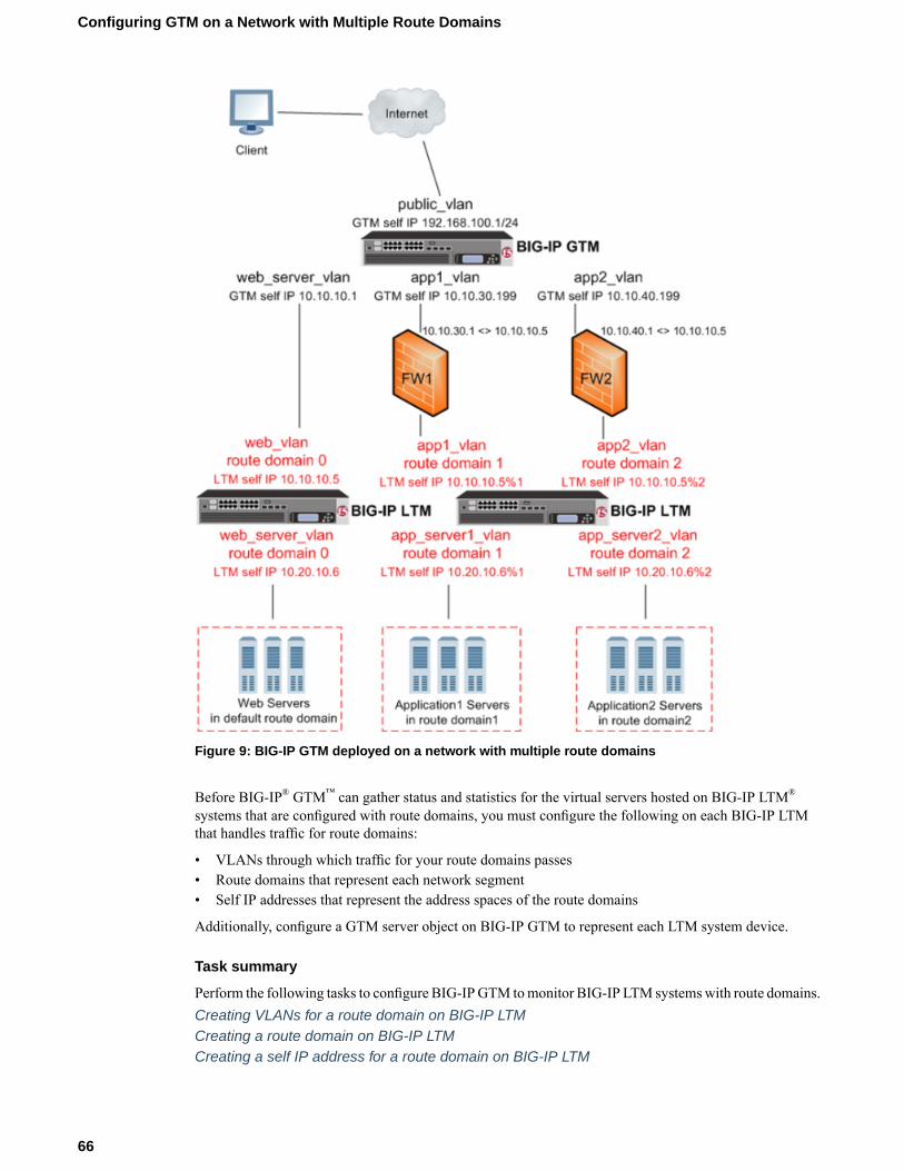
Figure 9: BIG-IP GTM deployed on a network with multiple route domains
Before BIG-IP® GTM™ can gather status and statistics for the virtual servers hosted on BIG-IP LTM®
systems that are configured with route domains, you must configure the following on each BIG-IP LTMthat handles traffic for route domains:
• VLANs through which traffic for your route domains passes• Route domains that represent each network segment• Self IP addresses that represent the address spaces of the route domains
Additionally, configure a GTM server object on BIG-IP GTM to represent each LTM system device.
Task summary
Perform the following tasks to configure BIG-IPGTM tomonitor BIG-IP LTM systemswith route domains.Creating VLANs for a route domain on BIG-IP LTMCreating a route domain on BIG-IP LTMCreating a self IP address for a route domain on BIG-IP LTM
66
Configuring GTM on a Network with Multiple Route Domains
Defining a server for a route domain on BIG-IP GTM
Creating VLANs for a route domain on BIG-IP LTM
Create two VLANs on BIG-IP® LTM® through which traffic can pass to a route domain.
1. On the Main tab, click Network > VLANs.The VLAN List screen opens.
2. Click Create.The New VLAN screen opens.
3. In the Name field, type external.4. In the Tag field, type a numeric tag, from 1-4094, for the VLAN, or leave the field blank if you want
the BIG-IP system to automatically assign a VLAN tag.The VLAN tag identifies the traffic from hosts in the associated VLAN.
5. If you want to use Q-in-Q (double) tagging, use theCustomer Tag setting to perform the following twosteps. If you do not see the Customer Tag setting, your hardware platform does not support Q-in-Qtagging and you can skip this step.a) From the Customer Tag list, select Specify.b) Type a numeric tag, from 1-4094, for the VLAN.
The customer tag specifies the inner tag of any frame passing through the VLAN.
6. For the Interfaces setting:a) From the Interface list, select an interface number.b) From the Tagging list, select Tagged or Untagged.
Select Tagged when you want traffic for that interface to be tagged with a VLAN ID.c) If you specified a numeric value for theCustomer Tag setting and from theTagging list you selected
Tagged, then from the Tag Mode list, select a value.d) Click Add.e) Repeat these steps for each interface that you want to assign to the VLAN.
7. If you want the system to verify that the return route to an initial packet is the same VLAN from whichthe packet originated, select the Source Check check box.
8. Click Finished.The screen refreshes, and displays the new VLAN in the list.
Repeat this procedure, but in Step 3, name the second VLAN internal.
Creating a route domain on BIG-IP LTM
Ensure that VLANs exist on BIG-IP® LTM®, before you create a route domain.
You can create a route domain on a BIG-IP system to segment (isolate) network traffic on your network.
1. On the Main tab, click Network > Route Domains.The Route Domain List screen opens.
2. Click Create.The New Route Domain screen opens.
3. In the ID field, type an ID number for the route domain.
67
BIG-IP® Global Traffic Manager™: Implementations
This ID must be unique on the BIG-IP system; that is, no other route domain on the system can havethis ID.
4. In the Description field, type a description of the route domain.For example: This route domain applies to traffic for application MyApp.
5. For the Strict Isolation setting, select the Enabled check box to restrict traffic in this route domainfrom crossing into another route domain.
6. For the Parent Name setting, retain the default value.7. For theVLANs setting, move the external and internalVLANs from theAvailable list, to theMembers
list.Configuring this setting ensures that the BIG-IP system immediately associates any self IP addressespertaining to the selected VLANs with this route domain.
8. Click Finished.The system displays a list of route domains on the BIG-IP system.
Create additional route domains based on your network configuration.
Creating a self IP address for a route domain on BIG-IP LTM
Ensure that VLANs exist on BIG-IP®LTM®, before you begin creating a self IP address for a route domain.
Create a self IP address on the BIG-IP system that resides in the address space of the route domain.
1. On the Main tab, click Network > Self IPs.2. Click Create.
The New Self IP screen opens.3. In the Name field, type a unique name for the self IP address.4. In the IP Address field, type an IP address.
This IP address must represent a self IP address in a route domain. Use the format x.x.x.x%n, wheren is the route domain ID, for example, 10.1.1.1%1.The system accepts IPv4 and IPv6 addresses.
5. In the Netmask field, type the full network mask for the specified IP address.
For example, you can type ffff:ffff:ffff:ffff:0000:0000:0000:0000 orffff:ffff:ffff:ffff::.
6. From the VLAN/Tunnel list, select the VLAN that you assigned to the route domain that contains thisself IP address.
7. From the Port Lockdown list, select Allow Default.8. Click Finished.
The screen refreshes, and displays the new self IP address.
Create additional self IP addresses based on your network configuration.
Defining a server for a route domain on BIG-IP GTM
Ensure that at least one data center exists in the configuration.
On BIG-IP® GTM™, define a server object to represent each LTM system device.
1. On the Main tab, click DNS > GSLB > Servers.
68
Configuring GTM on a Network with Multiple Route Domains

The Server List screen opens.2. Click Create.
The New Server screen opens.3. In the Name field, type a name for the server.
Important: Server names are limited to 63 characters.
4. From the Product list, select either BIG-IP System (Single) or BIG-IP System (Redundant).The server type determines the metrics that the system can collect from the server.
5. In the Address List area, add the self IP address that you assigned to the VLAN that you assigned to theroute domain.
Important: Do not include the route domain ID in this IP address. Use the format x.x.x.x, for example,10.10.10.1.
6. From the Data Center list, select the data center where the server resides.7. From the Prober Pool list, select one of the following.
DescriptionOption
By default, a server inherits the Prober pool assigned to the datacenter in which the server resides.
Inherit from Data Center
Select the Prober pool that contains the BIG-IP systems that youwant to perform monitor probes of this server.
Prober pool name
Note: The selected Prober pool must reside in the same route domain as the servers you want the poolmembers to probe.
8. In the Health Monitors area, assign the bigipmonitor to the server by moving it from the Available listto the Selected list.
9. From the Virtual Server Discovery list, select Enabled.10. Click Create.
The New Server screen opens.11. In the server list, click the name of the LTM system that you just created.
The Server Properties screen opens.12. On the menu bar, click Virtual Servers.
A list of the virtual servers configured on the server displays.13. From the Resources list, select Advanced.
Additional settings display.14. Select the Expose Route Domains check box.15. Click Update.
Repeat these steps to create a GTM server object to represent another LTM system device.
Implementation result
You now have an implementation in which BIG-IP GTM monitors BIG-IP LTM virtual servers on thevarious route domains in your network.
69
BIG-IP® Global Traffic Manager™: Implementations

Setting Up a BIG-IP GTM Redundant System Configuration
Overview: Configuring a BIG-IP GTM redundant system
You can configure BIG-IP® Global Traffic Manager™ (GTM™) in a redundant system configuration, whichis a set of two BIG-IP GTM systems: one operating as the active unit, the other operating as the standbyunit. If the active unit goes offline, the standby unit immediately assumes responsibility for managing DNStraffic. The new active unit remains active until another event occurs that would cause the unit to go offline,or you manually reset the status of each unit.
Task Summary
Perform the following tasks to configure a BIG-IP GTM redundant system configuration.
Before you begin, ensure that the Setup utility was run on both devices. During the Setup process, you createVLANs internal and external and the associated floating and non-floating IP addresses, and VLANHA andthe associated non-floating self IP address. You also configure the devices to be in an active-standbyredundant system configuration.Defining an NTP serverCreating listeners to identify DNS trafficDefining a data centerDefining a server to represent each BIG-IP systemEnabling global traffic configuration synchronizationRunning the gtm_add script
Defining an NTP server
Define a Network Time Protocol (NTP) server that both BIG-IP® GTM™ systems use during configurationsynchronization.
Important: Perform these steps on both the active and standby systems.
1. On the Main tab, click System > Configuration > Device > NTP.The NTP Device configuration screen opens.
2. For the Time Server Lookup List setting, in theAddress field, type the IP address of the NTP that youwant to add. Then click Add.
Note: If you did not disable DHCP before the first boot of the BIG-IP system, and if the DHCP serverprovides the information about your NTP server, then this field is automatically populated.
3. For the Time Server List setting, in the Address field, type the IP address of the NTP server that youwant to add. Then click Add.For this example, type 192.168.5.15.
Note: If you did not disable DHCP before the first boot of the BIG-IP system, and if the DHCP serverprovides the information about your NTP server, then this field is automatically populated.
4. For the Time Server List setting, in the Address field, type the IP address of an NTP server that youwant to add. Then click Add.
Note: If you are using Dynamic Host Configuration Protocol (DHCP) to assign IP addresses, then theBIG-IP system automatically populates the Address field with the fully-qualified domain name (FQDN)of the NTP server.
5. Repeat the preceding step as needed.6. Click Update.
During configuration synchronization, the systems use this time value to determine if any newer configurationfiles exist.
Creating listeners to identify DNS traffic
Create listeners to identify the DNS traffic that BIG-IP® GTM™ handles. The best practice is to create fourlisteners: one with an IPv4 address that handles UDP traffic, and one with the same IPv4 address that handlesTCP traffic; one with an IPv6 address that handles UDP traffic, and one with the same IPv6 address thathandles TCP traffic.
Note: DNS zone transfers use TCP port 53. If you do not configure listeners for TCP the client mightreceive the error: connection refused or TCP RSTs.
If you have multiple GTM systems in a device group, perform these steps on only one system.
1. On the Main tab, click DNS > Delivery > Listeners.The Listeners List screen opens.
2. Click Create.The Listeners properties screen opens.
3. In the Name field, type a unique name for the listener.4. For the Destination setting, in theAddress field, type an IPv4 address on which GTM listens for network
traffic.5. In the Service area, from the Protocol list, select UDP.6. Click Finished.
Create another listener with the same IPv4 address and configuration, but select TCP from the Protocollist. Then, create two more listeners, configuring both with the same IPv6 address, but one with the UDPprotocol and one with the TCP protocol.
Defining a data center
On BIG-IP®GTM™, create a data center to contain the servers that reside on a subnet of your network.
1. On the Main tab, click DNS > GSLB > Data Centers.The Data Center List screen opens.
2. Click Create.The New Data Center screen opens.
3. In the Name field, type a name to identify the data center.
Important: The data center name is limited to 63 characters.
72
Setting Up a BIG-IP GTM Redundant System Configuration
4. In the Location field, type the geographic location of the data center.5. In the Contact field, type the name of either the administrator or the department that manages the data
center.6. From the State list, select Enabled.7. Click Finished.
Now you can create server objects and assign them to this data center.
Repeat these steps to create additional data centers.
Defining a server to represent each BIG-IP system
Ensure that the data centers where the BIG-IP® GTM™ systems reside exist in the configuration.
Using this procedure, create two servers on the active BIG-IP system, one that represents the active systemand one that represents the standby system.
Important: Perform this procedure on only the active system.
1. On the Main tab, click DNS > GSLB > Servers.The Server List screen opens.
2. Click Create.The New Server screen opens.
3. In the Name field, type a name for the server.
Important: Server names are limited to 63 characters.
4. From the Product list, select BIG-IP System (Redundant).The server type determines the metrics that the system can collect from the server.
5. In the Address List area, add the IP address of the server.
Important: You must use a self IP address for a BIG-IP® system; you cannot use the management IPaddress.
6. In the Address List area, add the IP addresses of the back up system using the Peer Address List setting.a) Type an external (public) IP address in the Address field, and then click Add.b) Type an internal (private) IP address in the Translation field, and then click Add.
You can add more than one IP address, depending on how the server interacts with the rest of yournetwork.
7. From the Data Center list, select the data center where the server resides.8. From the Virtual Server Discovery list, select Disabled.9. Click Create.
The Server List screen opens displaying the new server in the list.
Enabling global traffic configuration synchronization
Enable global traffic configuration synchronization options and assign a name to the GTM synchronizationgroup.
73
BIG-IP® Global Traffic Manager™: Implementations

1. On the Main tab, click DNS > Settings > GSLB > General.The General configuration screen opens.
2. Select the Synchronize check box.3. In the Group Name field, type the name of the synchronization group.4. In the Time Tolerance field, type the maximum age difference in seconds, between the sets of
configuration files on the systems in a GTM configuration synchronization group.5. Select the Synchronize DNS Zone Files check box.6. Click Update.
Running the gtm_add script
You must run the gtm_add script from the standby system.
Note: You must perform this task from the command-line interface.
1. On the new BIG-IP® GTM™ system, log in to the command-line interface.2. Type gtm_add, and press Enter.3. Press the y key to start the gtm_add script.4. Type the IP address of the existing GTM system, and press Enter.
The gtm_add script acquires configuration data from the active system; once this process completes, youhave successfully created a redundant system consisting of two GTM systems.
74
Setting Up a BIG-IP GTM Redundant System Configuration
Authenticating with SSL Certificates Signed by a Third Party
Overview: Authenticating with SSL certificates signed by a third party
BIG-IP® systems use Secure Sockets Layer (SSL) authentication to verify the authenticity of the credentialsof systems with which data exchange is necessary.
BIG-IP software includes a self-signed SSL certificate. If your network includes one or more certificateauthority (CA) servers, you can also install SSL certificates that are signed by a third party. The BIG-IPsystems exchange SSL certificates, and use a CA server to verify the authenticity of the certificates.
The big3d agent on all BIG-IP systems and the gtmd agent on BIG-IP Global Traffic Manager™ (GTM™)systems use the certificates to authenticate communication between the systems.
About SSL authentication levels
SSL supports ten levels of authentication (also known as certificate depth):
• Level 0 certificates (self-signed certificates) are verified by the system to which they belong.• Level 1 certificates are authenticated by a CA server that is separate from the system.• Levels 2 - 9 certificates are authenticated by additional CA servers that verify the authenticity of other
servers. These multiple levels of authentication (referred to as certificate chains) allow for a tieredverification system that ensures that only authorized communications occur between servers.
Configuring Level 1 SSL authentication
You can configure BIG-IP® systems for Level 1 SSL authentication. Before you begin, ensure that thesystems you are configuring include the following:
• A signed certificate/key pair.• The root certificate from the CA server.
Task SummaryImporting the device certificate signed by a CA serverImporting the root certificate for the gtmd agentImporting the root certificate for the big3d agentVerifying the certificate exchange
Importing the device certificate signed by a CA server
To configure the BIG-IP® system for Level 1 SSL authentication, import the device certificate signed bythe CA server.

Note: Perform this procedure on all BIG-IP® systems that you want to handle Level 1 SSL authentication.
1. On the Main tab, click System > Device Certificates.The Device Certificate screen opens.
2. Click Import.3. From the Import Type list, select Certificate and Key.4. For the Certificate Source setting, select Upload File and browse to select the certificate signed by the
CA server.5. For the Key Source setting, select Upload File and browse to select the device key file.6. Click Import.
Importing the root certificate for the gtmd agent
Before you start this procedure, ensure that you have the root certificate from your CA server available.
To set up the system to use a third-party certificate signed by a CA server, replace the existing certificatefile for the gtmd agent with the root certificate of your CA server.
Note: Perform this procedure on only one BIG-IP® GTM™ system in the GTM synchronization group. Thesystem automatically synchronizes the setting with the other systems in the group.
1. On the Main tab, click DNS > GSLB > Servers > Trusted Server Certificates.The Trusted Server Certificates screen opens.
2. Click Import.3. From the Import Method list, select Replace.4. For the Certificate Source setting, select Upload File and browse to select the root certificate file.5. Click Import.
Importing the root certificate for the big3d agent
Before you start this procedure, ensure that the root certificate from your CA server is available.
Note: Perform this procedure on all BIG-IP® systems that you want to configure for Level 1 SSLauthentication.
1. On the Main tab, click System > Device Certificates > Trusted Device Certificates.The Trusted Device Certificates screen opens.
2. Click Import.3. From the Import Method list, select Replace.4. For the Certificate Source setting, select Upload File and browse to select the certificate signed by the
CA server.5. Click Import.
76
Authenticating with SSL Certificates Signed by a Third Party

Verifying the certificate exchange
You can verify that you installed the certificate correctly, by running the following commands on all BIG-IP®
systems that you configured for Level 1 SSL authentication.
iqdump <IP address of BIG-IP you are testing>iqdump <IP address of BIG-IP peer system, if testing a redundant systemconfiguration>
If the certificate was installed correctly, these commands display a continuous stream of information.
Implementation Results
The BIG-IP® systems are now configured for Level 1 SSL authentication.
Configuring certificate chain SSL authentication
You can configure BIG-IP® systems for certificate chain SSL authentication.
Task SummaryCreating a certificate chain fileImporting the device certificate from the last CA server in the chainImporting a certificate chain file for the gtmd agentImporting a certificate chain for the big3d agentVerifying the certificate chain exchange
Creating a certificate chain file
Before you start this procedure, ensure that you have the certificate files from your CA servers available.
Create a certificate chain file that you can use to replace the existing certificate file.
1. Using a text editor, create an empty file for the certificate chain.2. Still using a text editor, copy an individual certificate from its own certificate file and paste the certificate
into the file you created in step 1.3. Repeat step 2 for each certificate that you want to include in the certificate chain.
You now have a certificate chain file.
Importing the device certificate from the last CA server in the chain
Import the device certificate signed by the last CA in the certificate chain.
77
BIG-IP® Global Traffic Manager™: Implementations

Note: Perform this procedure on all BIG-IP systems that you want to configure for certificate chain SSLauthentication.
1. On the Main tab, click System > Device Certificates.The Device Certificate screen opens.
2. Click Import.3. From the Import Type list, select Certificate and Key.4. For the Certificate Source setting, select Upload File and browse to select the certificate signed by the
CA server.5. For the Key Source setting, select Upload File and browse to select the device key file.6. Click Import.
Importing a certificate chain file for the gtmd agent
Before importing a certificate chain file for the gtmd agent, ensure that you have the certificate chain fileavailable.
Replace the existing certificate file on the system with a certificate chain file.
Note: Perform these steps on only one BIG-IP® GTM™ in a GTM synchronization group. The systemautomatically synchronizes the setting with the other systems in the group.
1. On the Main tab, click DNS > GSLB > Servers > Trusted Server Certificates.The Trusted Server Certificates screen opens.
2. Click Import.3. From the Import Method list, select Replace.4. For the Certificate Source setting, select Upload File and browse to select the device certificate for
the last CA in the certificate chain.5. Click Import.
Importing a certificate chain for the big3d agent
Before importing a certificate chain for the big3d agent, ensure that the certificate chain file is available.
Note: Perform these steps on all BIG-IP® systems that you want to configure for certificate chain SSLauthentication.
1. On the Main tab, click System > Device Certificates > Trusted Device Certificates.The Trusted Device Certificates screen opens.
2. Click Import.3. From the Import Method list, select Replace.4. For the Certificate Source setting, select Upload File and browse to select the certificate chain file.5. Click Import.
78
Authenticating with SSL Certificates Signed by a Third Party

Verifying the certificate chain exchange
You can verify that you installed the certificate chain correctly running the following commands on all thesystems you configure for certificate chain SSL authentication.
iqdump <IP address of BIG-IP system you are testing>iqdump <IP address of BIG-IP peer system, if testing a redundant systemconfiguration>
If the certificate chain was installed correctly, these commands display a continuous stream of information.
Implementation result
The BIG-IP® systems are now configured for certificate chain SSL authentication. For information abouttroubleshooting BIG-IP device certificates, see SOL8187 on AskF5.com (www.askf5.com).
79
BIG-IP® Global Traffic Manager™: Implementations

Configuring a TTL in a DNS NoError Response
Overview: Configuring a TTL in an IPv6 DNS NoError Response
You can configure BIG-IP® GTM™ to return IPv6 DNS NoError responses that include a TTL. With thisconfiguration, local DNS servers can cache a negative response. Negative caching reduces both the responsetime for negative DNS responses and the number of messages that must be sent between resolvers and localDNS servers.
About SOA records and negative caching
A start of authority SOA record contains a TTL by which a local DNS server can be configured to cache aDNS NoError response to an IPv6 query.
Task summary
You can configure GTM™ to provide a negative caching TTL for a domain name by performing thesespecific tasks.Creating a poolCreating a wide IP that provides for negative caching
Creating a pool
Ensure that at least one virtual server exists in the configuration before you start to create a load balancingpool.
Create a pool to which the system can load balance global traffic.
1. On the Main tab, click DNS > GSLB > Pools.The Pools list screen opens.
2. Click Create.3. In the Name field, type a name for the pool.
Names must begin with a letter, and can contain only letters, numbers, and the underscore (_) character.
Important: The pool name is limited to 63 characters.
4. For the Health Monitors setting, in the Available list, select a monitor type, and move the monitor tothe Active list.
Tip: Hold the Shift or Ctrl key to select more than one monitor at a time.
5. For the Member List setting, add virtual servers as members of this load balancing pool.The system evaluates the virtual servers (pool members) in the order in which they are listed. A virtualserver can belong to more than one pool.a) Select a virtual server from the Virtual Server list.b) Click Add.
6. Click Finished.
Creating a wide IP that provides for negative caching
Ensure that at least one global load balancing pool exists in the configuration before you create a wide IP.
Create a wide IP configured in a manner where BIG-IP®GTM™ returns an SOA record that contains a TTLwith an IPv6 DNS NoError response. With this configuration, the local DNS servers can cache a negativeresponse and thus provide faster responses to DNS queries.
1. On the Main tab, click DNS > GSLB >Wide IPs.The Wide IP List screen opens.
2. Click Create.The New Wide IP screen opens.
3. From the General Properties list, select Advanced.4. In the Name field, type a name for the wide IP.
Tip: You can use two different wildcard characters in the wide IP name: asterisk (*) to represent severalcharacters and question mark (?) to represent a single character. This reduces the number of aliasesyou have to add to the configuration.
5. From the IPv6 NoError Response list, select Enabled.With this option enabled, the system responds faster to IPv6 requests for which it does not have AAAArecords configured.
6. In the IPv6 NoError TTL field, type the number of seconds that the local DNS servers consider theIPv6NoError response to be valid.When you set this value, youmust enable the IPv6NoError Responsesetting as well.
7. From the Pool list, select the pools that this wide IP uses for load balancing.The system evaluates the pools based on the wide IP load balancing method configured.a) From the Pool list, select a pool.
A pool can belong to more than one wide IP.b) Click Add.
8. Click Finished.
Implementation result
You now have an implementation in which GTM™ returns a TTL in an IPv6 DNS NoError response for aweb site represented by a wide IP in the GTM configuration.
82
Configuring a TTL in a DNS NoError Response
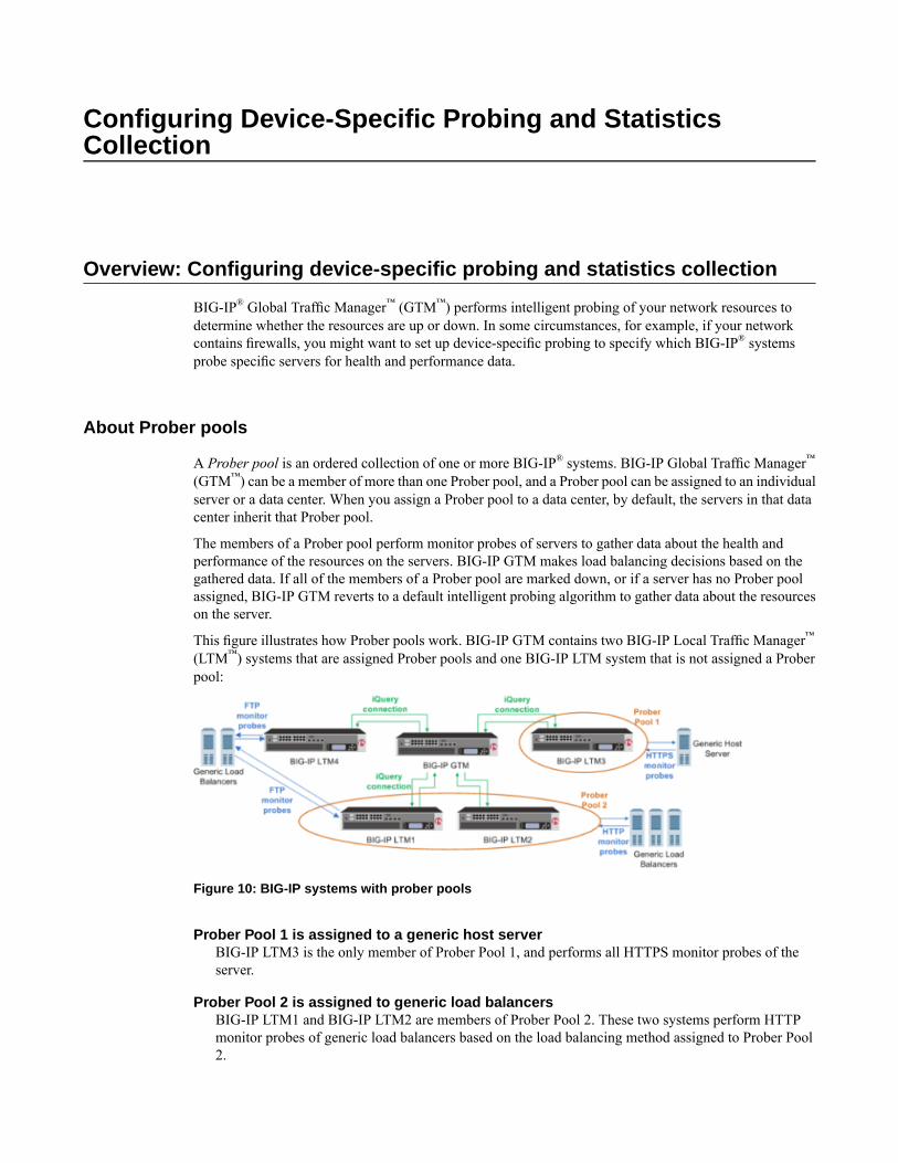
Configuring Device-Specific Probing and StatisticsCollection
Overview: Configuring device-specific probing and statistics collection
BIG-IP® Global Traffic Manager™ (GTM™) performs intelligent probing of your network resources todetermine whether the resources are up or down. In some circumstances, for example, if your networkcontains firewalls, you might want to set up device-specific probing to specify which BIG-IP® systemsprobe specific servers for health and performance data.
About Prober pools
A Prober pool is an ordered collection of one or more BIG-IP® systems. BIG-IP Global Traffic Manager™
(GTM™) can be a member of more than one Prober pool, and a Prober pool can be assigned to an individualserver or a data center. When you assign a Prober pool to a data center, by default, the servers in that datacenter inherit that Prober pool.
The members of a Prober pool perform monitor probes of servers to gather data about the health andperformance of the resources on the servers. BIG-IP GTM makes load balancing decisions based on thegathered data. If all of the members of a Prober pool are marked down, or if a server has no Prober poolassigned, BIG-IP GTM reverts to a default intelligent probing algorithm to gather data about the resourceson the server.
This figure illustrates how Prober pools work. BIG-IP GTM contains two BIG-IP Local Traffic Manager™
(LTM™) systems that are assigned Prober pools and one BIG-IP LTM system that is not assigned a Proberpool:
Figure 10: BIG-IP systems with prober pools
Prober Pool 1 is assigned to a generic host serverBIG-IP LTM3 is the only member of Prober Pool 1, and performs all HTTPS monitor probes of theserver.
Prober Pool 2 is assigned to generic load balancersBIG-IP LTM1 and BIG-IP LTM2 are members of Prober Pool 2. These two systems perform HTTPmonitor probes of generic load balancers based on the load balancing method assigned to Prober Pool2.
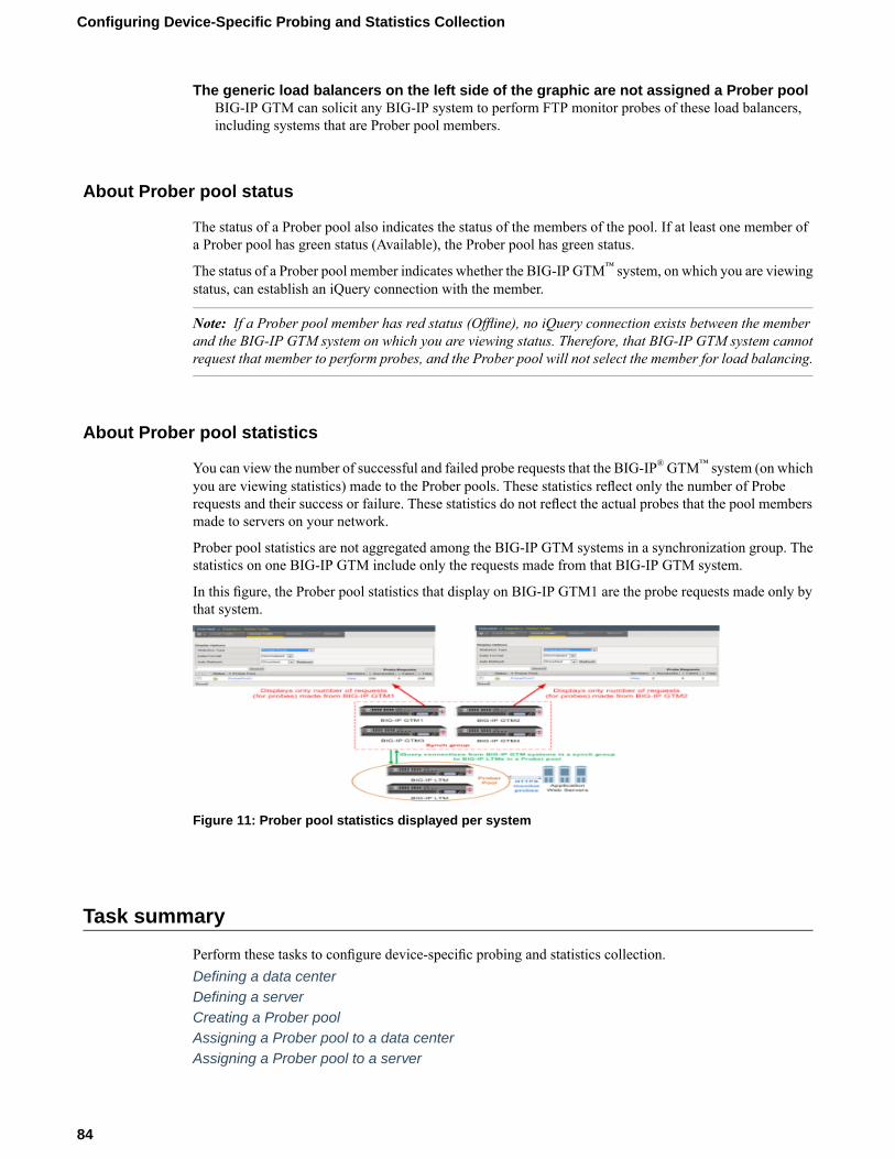
The generic load balancers on the left side of the graphic are not assigned a Prober poolBIG-IP GTM can solicit any BIG-IP system to perform FTP monitor probes of these load balancers,including systems that are Prober pool members.
About Prober pool status
The status of a Prober pool also indicates the status of the members of the pool. If at least one member ofa Prober pool has green status (Available), the Prober pool has green status.
The status of a Prober pool member indicates whether the BIG-IP GTM™ system, on which you are viewingstatus, can establish an iQuery connection with the member.
Note: If a Prober pool member has red status (Offline), no iQuery connection exists between the memberand the BIG-IP GTM system on which you are viewing status. Therefore, that BIG-IP GTM system cannotrequest that member to perform probes, and the Prober pool will not select the member for load balancing.
About Prober pool statistics
You can view the number of successful and failed probe requests that the BIG-IP®GTM™ system (on whichyou are viewing statistics) made to the Prober pools. These statistics reflect only the number of Proberequests and their success or failure. These statistics do not reflect the actual probes that the pool membersmade to servers on your network.
Prober pool statistics are not aggregated among the BIG-IP GTM systems in a synchronization group. Thestatistics on one BIG-IP GTM include only the requests made from that BIG-IP GTM system.
In this figure, the Prober pool statistics that display on BIG-IP GTM1 are the probe requests made only bythat system.
Figure 11: Prober pool statistics displayed per system
Task summary
Perform these tasks to configure device-specific probing and statistics collection.Defining a data centerDefining a serverCreating a Prober poolAssigning a Prober pool to a data centerAssigning a Prober pool to a server
84
Configuring Device-Specific Probing and Statistics Collection
Viewing Prober pool statistics and statusDetermining which Prober pool member marked a resource down
Defining a data center
On BIG-IP®GTM™, create a data center to contain the servers that reside on a subnet of your network.
1. On the Main tab, click DNS > GSLB > Data Centers.The Data Center List screen opens.
2. Click Create.The New Data Center screen opens.
3. In the Name field, type a name to identify the data center.
Important: The data center name is limited to 63 characters.
4. In the Location field, type the geographic location of the data center.5. In the Contact field, type the name of either the administrator or the department that manages the data
center.6. From the State list, select Enabled.7. Click Finished.
Now you can create server objects and assign them to this data center.
Repeat these steps to create additional data centers.
Defining a server
Ensure that at least one data center exists in the configuration.
On BIG-IP® GTM™, define a server that represents a physical server in your network. Repeat these stepsfor each server in your network, including the GTM itself, other BIG-IP systems, other load balancers, andthird-party host servers.
Important: At a minimum, you must define two servers, one that represents GTM and one that representsanother managed server (either a load balancing or host server).
1. On the Main tab, click DNS > GSLB > Servers.The Server List screen opens.
2. Click Create.The New Server screen opens.
3. In the Name field, type a name for the server.
Important: Server names are limited to 63 characters.
4. From the Product list, select the server type.The server type determines the metrics that the system can collect from the server.
Note: If your network uses a server that is not on this list, use the Generic Load Balancer or GenericHost option.
5. In the Address List area, add the IP addresses of the server.
85
BIG-IP® Global Traffic Manager™: Implementations
a) Type an external (public) IP address in the Address field, and then click Add.b) If you use NAT, type an internal (private) IP address in the Translation field, and then click Add.
You can add more than one IP address, depending on how the server interacts with the rest of yournetwork.
6. From the Data Center list, select the data center where the server resides.7. In the Health Monitors area, assign health monitors to the server by moving them from the Available
list to the Selected list.
Tip: If the server is a BIG-IP system, use the bigip monitor. If the server is a generic host, considerusing the gateway_icmpmonitor, because this monitor simply checks that the server responds to a ping.
8. From the Virtual Server Discovery list, select how you want virtual servers to be added to the system.DescriptionOption
The system does not use the discovery feature to automatically add virtual servers.This is the default value. Use this option for a standalone GTM system or for a
Disabled
GTM/LTM® combo system when you plan to manually add virtual servers to thesystem, or if your network uses multiple route domains.
The system uses the discovery feature to automatically add virtual servers. Usethis option for a GTM/LTM combo system when you want the GTM system todiscover LTM virtual servers.
Enabled
The system uses the discovery feature to automatically add virtual servers anddoes not delete any virtual servers that already exist. Use this option for a
Enabled (NoDelete)
GTM/LTM combo system when you want the GTM system to discover LTMvirtual servers.
9. Click Create.The Server List screen opens displaying the new server in the list.
Creating a Prober pool
Obtain a list of the BIG-IP® systems in your network and ensure that a server object is configured on theBIG-IP GTM™for each system.
Create a Prober pool that contains the BIG-IP systems that you want to performmonitor probes of a specificserver or the servers in a data center.
1. On the Main tab, click DNS > GSLB > Prober Pools.The Prober Pool List screen opens.
2. Click Create.The New Prober Pool screen opens.
3. In the Name field, type a name for the Prober pool.
Important: Prober pool names are limited to 63 characters.
4. Select a method from the Load Balancing Method list.DescriptionOption
GTM load balances monitor probes among the members of a Proberpool in a circular and sequential pattern.
Round Robin
86
Configuring Device-Specific Probing and Statistics Collection
DescriptionOption
GTM selects the first available Prober pool member to perform amonitor probe.
Global Availability
5. Assign members to the pool by moving servers from the Available list to the Selected list.6. To reorder the members in the Selected list, choose a server and use the Up and Down buttons to move
the server to a different location in the list.The order of the servers in the list is important in relation to the load balancing method you selected.
7. Click Finished.
Assign the Prober pool to a data center or a server.
Assigning a Prober pool to a data center
Ensure that a Prober pool is available on the system.
To make a specific collection of BIG-IP® systems available to probe the servers in a data center, assign aProber pool to the data center.
1. On the Main tab, click DNS > GSLB > Data Centers.The Data Center List screen opens.
2. Click a data center name.The data center settings and values display.
3. From the Prober Pool list, select the Prober pool that contains the BIG-IP® systems that you want toperform monitor probes of the servers in this data center.By default, all of the servers in the data center inherit this Prober pool.
4. Click Update.
Assigning a Prober pool to a server
Ensure that a Prober pool is available on the system.
To specify which BIG-IP® systems perform monitor probes of a server, assign a Prober pool to the server.
1. On the Main tab, click DNS > GSLB > Servers.The Server List screen opens.
2. In the Server List, click a server name.The server settings and values display.
3. From the Prober Pool list, select one of the following.DescriptionOption
By default, a server inherits the Prober pool assigned to the datacenter in which the server resides.
Inherit from Data Center
Select the Prober pool that contains the BIG-IP systems that youwant to perform monitor probes of this server.
Prober pool name
4. Click Update.
87
BIG-IP® Global Traffic Manager™: Implementations

Viewing Prober pool statistics and status
You can view status and statistics for Prober pools and the members of the pools.
1. On the Main tab, click DNS > GSLB > Prober Pools.The Prober Pool List screen opens.
2. On the menu bar, click Statistics.The Global Traffic Statistics screen opens.
3. Click the Refresh button.The statistics are updated.
4. To view additional information about the status of a Prober pool, place your cursor over the icon in theStatus column.
5. To view additional information about the status of a Prober pool member, click View in the Memberscolumn, and then place your cursor over the icon in the Status column of a specific member.
Determining which Prober pool member marked a resource down
When a resource is marked down, you can open the BIG-IP®GTM™ log to view the SNMP trap and determinewhich member of a Prober pool marked the resource down.
1. On the Main tab, click System > Logs.The System logs screen opens.
2. On the menu bar, click Local Traffic.The Local Traffic logs screen opens.
3. You can either scroll through the log or search for a log entry about a specific event.
Implementation result
You now have an implementation in which a specific BIG-IP® system probes the resources on a specificserver, or the servers in a specific data center.
88
Configuring Device-Specific Probing and Statistics Collection
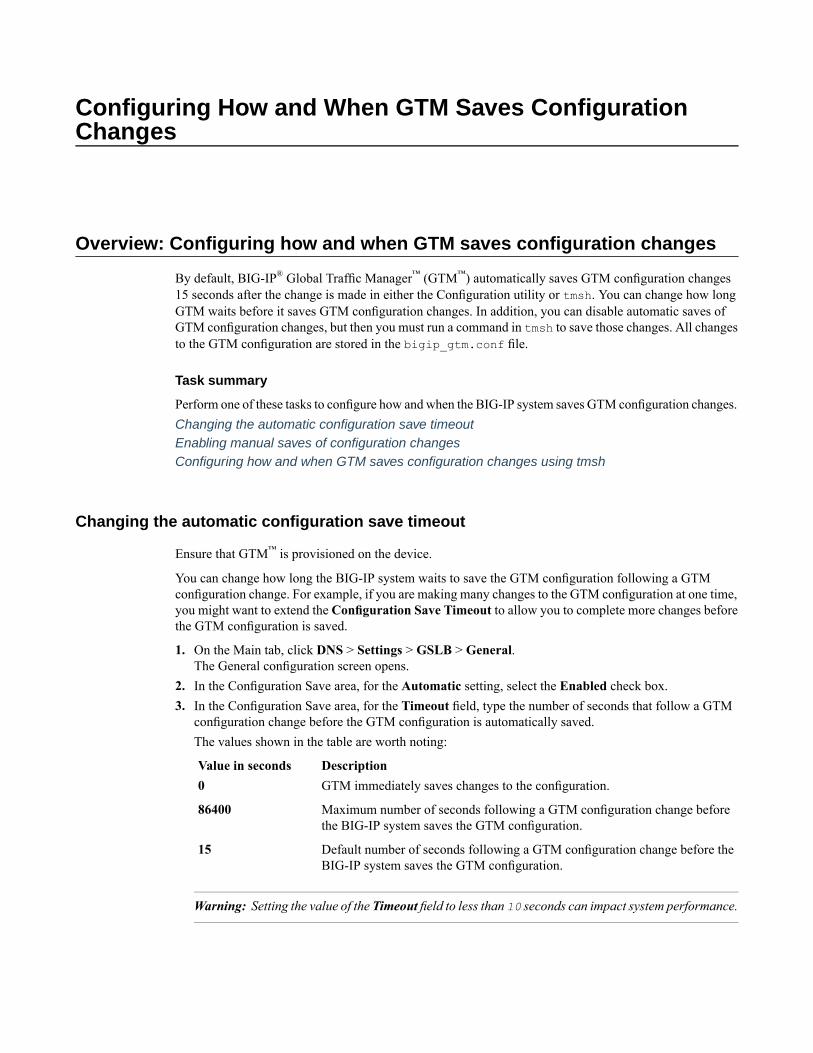
Configuring How and When GTM Saves ConfigurationChanges
Overview: Configuring how and when GTM saves configuration changes
By default, BIG-IP® Global Traffic Manager™ (GTM™) automatically saves GTM configuration changes15 seconds after the change is made in either the Configuration utility or tmsh. You can change how longGTM waits before it saves GTM configuration changes. In addition, you can disable automatic saves ofGTM configuration changes, but then you must run a command in tmsh to save those changes. All changesto the GTM configuration are stored in the bigip_gtm.conf file.
Task summary
Perform one of these tasks to configure how and when the BIG-IP system saves GTM configuration changes.Changing the automatic configuration save timeoutEnabling manual saves of configuration changesConfiguring how and when GTM saves configuration changes using tmsh
Changing the automatic configuration save timeout
Ensure that GTM™ is provisioned on the device.
You can change how long the BIG-IP system waits to save the GTM configuration following a GTMconfiguration change. For example, if you are making many changes to the GTM configuration at one time,you might want to extend the Configuration Save Timeout to allow you to complete more changes beforethe GTM configuration is saved.
1. On the Main tab, click DNS > Settings > GSLB > General.The General configuration screen opens.
2. In the Configuration Save area, for the Automatic setting, select the Enabled check box.3. In the Configuration Save area, for the Timeout field, type the number of seconds that follow a GTM
configuration change before the GTM configuration is automatically saved.The values shown in the table are worth noting:
DescriptionValue in secondsGTM immediately saves changes to the configuration.0
Maximum number of seconds following a GTM configuration change beforethe BIG-IP system saves the GTM configuration.
86400
Default number of seconds following a GTM configuration change before theBIG-IP system saves the GTM configuration.
15
Warning: Setting the value of the Timeout field to less than 10 seconds can impact system performance.
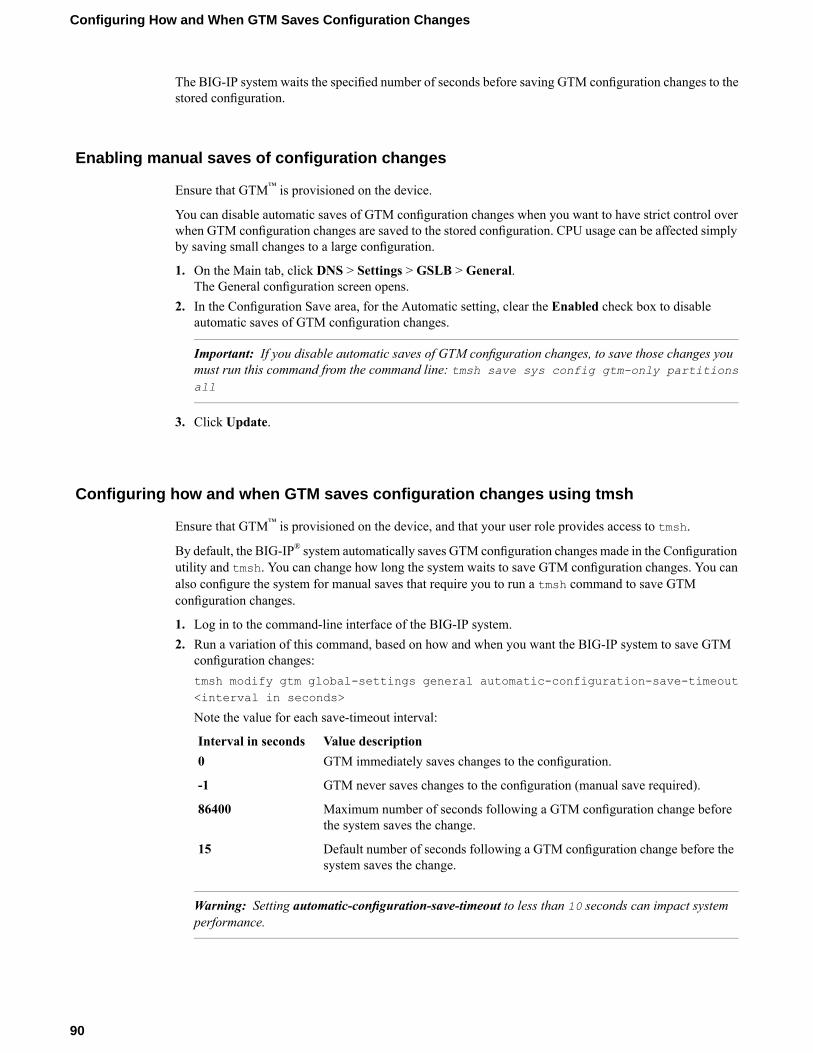
The BIG-IP system waits the specified number of seconds before saving GTM configuration changes to thestored configuration.
Enabling manual saves of configuration changes
Ensure that GTM™ is provisioned on the device.
You can disable automatic saves of GTM configuration changes when you want to have strict control overwhen GTM configuration changes are saved to the stored configuration. CPU usage can be affected simplyby saving small changes to a large configuration.
1. On the Main tab, click DNS > Settings > GSLB > General.The General configuration screen opens.
2. In the Configuration Save area, for the Automatic setting, clear the Enabled check box to disableautomatic saves of GTM configuration changes.
Important: If you disable automatic saves of GTM configuration changes, to save those changes youmust run this command from the command line: tmsh save sys config gtm-only partitionsall
3. Click Update.
Configuring how and when GTM saves configuration changes using tmsh
Ensure that GTM™ is provisioned on the device, and that your user role provides access to tmsh.
By default, the BIG-IP® system automatically saves GTM configuration changes made in the Configurationutility and tmsh. You can change how long the system waits to save GTM configuration changes. You canalso configure the system for manual saves that require you to run a tmsh command to save GTMconfiguration changes.
1. Log in to the command-line interface of the BIG-IP system.2. Run a variation of this command, based on how and when you want the BIG-IP system to save GTM
configuration changes:tmsh modify gtm global-settings general automatic-configuration-save-timeout<interval in seconds>
Note the value for each save-timeout interval:
Value descriptionInterval in secondsGTM immediately saves changes to the configuration.0
GTM never saves changes to the configuration (manual save required).-1
Maximum number of seconds following a GTM configuration change beforethe system saves the change.
86400
Default number of seconds following a GTM configuration change before thesystem saves the change.
15
Warning: Setting automatic-configuration-save-timeout to less than 10 seconds can impact systemperformance.
90
Configuring How and When GTM Saves Configuration Changes

GTMwaits the number of seconds you specify before saving GTM configuration changes. If you specified-1, then you must save the configuration manually using this command: tmsh save sys configgtm-only partitions all
91
BIG-IP® Global Traffic Manager™: Implementations

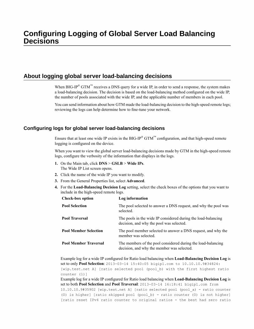
Configuring Logging of Global Server Load BalancingDecisions
About logging global server load-balancing decisions
When BIG-IP® GTM™ receives a DNS query for a wide IP, in order to send a response, the system makesa load-balancing decision. The decision is based on the load-balancing method configured on the wide IP,the number of pools associated with the wide IP, and the applicable number of members in each pool.
You can send information about howGTMmade the load-balancing decision to the high-speed remote logs;reviewing the logs can help determine how to fine-tune your network.
Configuring logs for global server load-balancing decisions
Ensure that at least one wide IP exists in the BIG-IP® GTM™ configuration, and that high-speed remotelogging is configured on the device.
When you want to view the global server load-balancing decisions made by GTM in the high-speed remotelogs, configure the verbosity of the information that displays in the logs.
1. On the Main tab, click DNS > GSLB >Wide IPs.The Wide IP List screen opens.
2. Click the name of the wide IP you want to modify.3. From the General Properties list, select Advanced.4. For the Load-Balancing Decision Log setting, select the check boxes of the options that you want to
include in the high-speed remote logs.Log informationCheck-box option
The pool selected to answer a DNS request, and why the pool wasselected.
Pool Selection
The pools in the wide IP considered during the load-balancingdecision, and why the pool was selected.
Pool Traversal
The pool member selected to answer a DNS request, and why themember was selected.
Pool Member Selection
The members of the pool considered during the load-balancingdecision, and why the member was selected.
Pool Member Traversal
Example log for a wide IP configured for Ratio load balancing when Load-Balancing Decision Log isset to only Pool Selection: 2013-03-14 15:40:05 bigip1.com to 10.10.10.9#34824:[wip.test.net A] [ratio selected pool (pool_b) with the first highest ratiocounter (1)]Example log for a wide IP configured for Ratio load balancing when Load-Balancing Decision Log isset to both Pool Selection and Pool Traversal: 2013-03-14 16:18:41 bigip1.com from10.10.10.9#35902 [wip.test.net A] [ratio selected pool (pool_a) - ratio counter(0) is higher] [ratio skipped pool (pool_b) - ratio counter (0) is not higher][ratio reset IPv4 ratio counter to original ratios - the best had zero ratio

count] [ratio selected pool (pool_a) - ratio counter (1) is not higher] [ratioselected pool (pool_b) - ratio counter (1) is not higher] [ratio selectedpool (pool_a) with the first highest ratio counter (1)]
94
Configuring Logging of Global Server Load Balancing Decisions
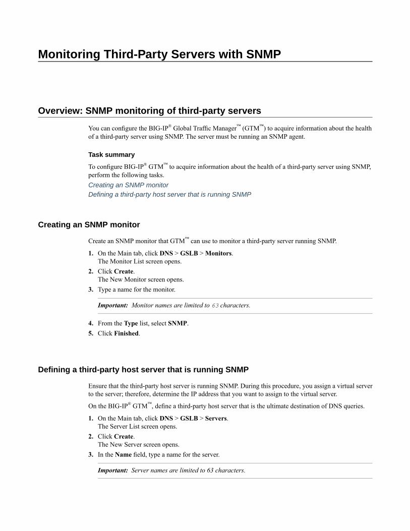
Monitoring Third-Party Servers with SNMP
Overview: SNMP monitoring of third-party servers
You can configure the BIG-IP® Global Traffic Manager™ (GTM™) to acquire information about the healthof a third-party server using SNMP. The server must be running an SNMP agent.
Task summary
To configure BIG-IP® GTM™ to acquire information about the health of a third-party server using SNMP,perform the following tasks.Creating an SNMP monitorDefining a third-party host server that is running SNMP
Creating an SNMP monitor
Create an SNMP monitor that GTM™ can use to monitor a third-party server running SNMP.
1. On the Main tab, click DNS > GSLB >Monitors.The Monitor List screen opens.
2. Click Create.The New Monitor screen opens.
3. Type a name for the monitor.
Important: Monitor names are limited to 63 characters.
4. From the Type list, select SNMP.5. Click Finished.
Defining a third-party host server that is running SNMP
Ensure that the third-party host server is running SNMP. During this procedure, you assign a virtual serverto the server; therefore, determine the IP address that you want to assign to the virtual server.
On the BIG-IP® GTM™, define a third-party host server that is the ultimate destination of DNS queries.
1. On the Main tab, click DNS > GSLB > Servers.The Server List screen opens.
2. Click Create.The New Server screen opens.
3. In the Name field, type a name for the server.
Important: Server names are limited to 63 characters.
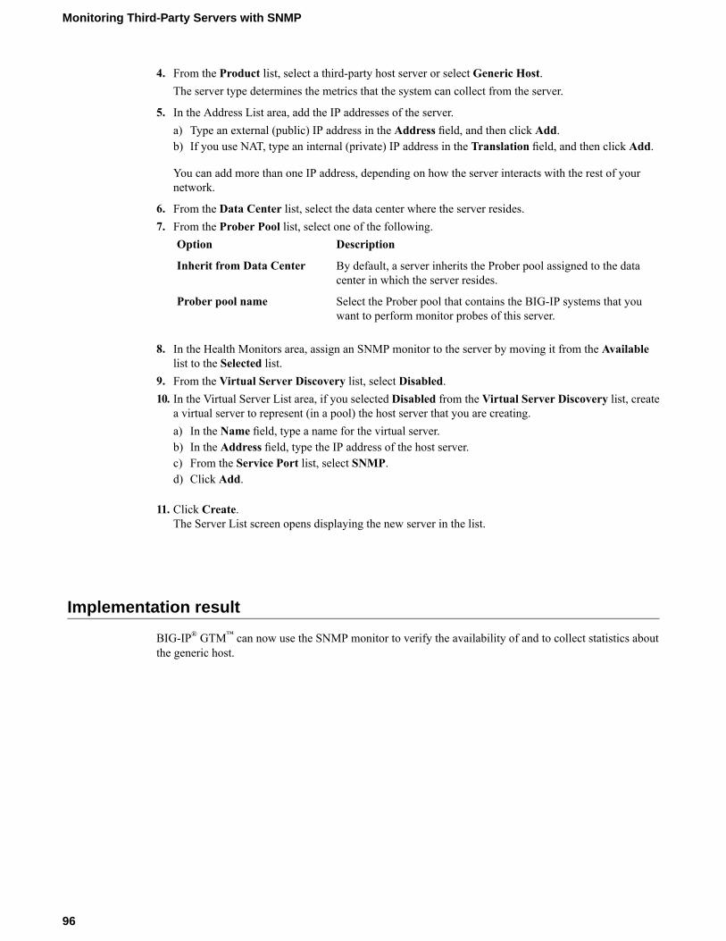
4. From the Product list, select a third-party host server or select Generic Host.The server type determines the metrics that the system can collect from the server.
5. In the Address List area, add the IP addresses of the server.a) Type an external (public) IP address in the Address field, and then click Add.b) If you use NAT, type an internal (private) IP address in the Translation field, and then click Add.
You can add more than one IP address, depending on how the server interacts with the rest of yournetwork.
6. From the Data Center list, select the data center where the server resides.7. From the Prober Pool list, select one of the following.
DescriptionOption
By default, a server inherits the Prober pool assigned to the datacenter in which the server resides.
Inherit from Data Center
Select the Prober pool that contains the BIG-IP systems that youwant to perform monitor probes of this server.
Prober pool name
8. In the Health Monitors area, assign an SNMP monitor to the server by moving it from the Availablelist to the Selected list.
9. From the Virtual Server Discovery list, select Disabled.10. In the Virtual Server List area, if you selected Disabled from the Virtual Server Discovery list, create
a virtual server to represent (in a pool) the host server that you are creating.a) In the Name field, type a name for the virtual server.b) In the Address field, type the IP address of the host server.c) From the Service Port list, select SNMP.d) Click Add.
11. Click Create.The Server List screen opens displaying the new server in the list.
Implementation result
BIG-IP® GTM™ can now use the SNMP monitor to verify the availability of and to collect statistics aboutthe generic host.
96
Monitoring Third-Party Servers with SNMP
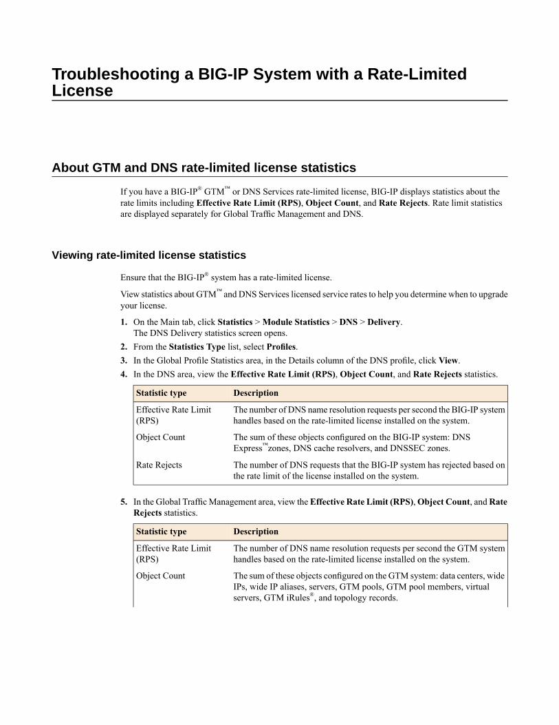
Troubleshooting a BIG-IP System with a Rate-LimitedLicense
About GTM and DNS rate-limited license statistics
If you have a BIG-IP® GTM™ or DNS Services rate-limited license, BIG-IP displays statistics about therate limits including Effective Rate Limit (RPS), Object Count, and Rate Rejects. Rate limit statisticsare displayed separately for Global Traffic Management and DNS.
Viewing rate-limited license statistics
Ensure that the BIG-IP® system has a rate-limited license.
View statistics about GTM™ and DNS Services licensed service rates to help you determine when to upgradeyour license.
1. On the Main tab, click Statistics >Module Statistics > DNS > Delivery.The DNS Delivery statistics screen opens.
2. From the Statistics Type list, select Profiles.3. In the Global Profile Statistics area, in the Details column of the DNS profile, click View.4. In the DNS area, view the Effective Rate Limit (RPS), Object Count, and Rate Rejects statistics.
DescriptionStatistic type
The number of DNS name resolution requests per second the BIG-IP systemhandles based on the rate-limited license installed on the system.
Effective Rate Limit(RPS)
The sum of these objects configured on the BIG-IP system: DNSExpress™zones, DNS cache resolvers, and DNSSEC zones.
Object Count
The number of DNS requests that the BIG-IP system has rejected based onthe rate limit of the license installed on the system.
Rate Rejects
5. In the Global TrafficManagement area, view theEffective Rate Limit (RPS),Object Count, andRateRejects statistics.
DescriptionStatistic type
The number of DNS name resolution requests per second the GTM systemhandles based on the rate-limited license installed on the system.
Effective Rate Limit(RPS)
The sum of these objects configured on the GTM system: data centers, wideIPs, wide IP aliases, servers, GTM pools, GTM pool members, virtualservers, GTM iRules®, and topology records.
Object Count
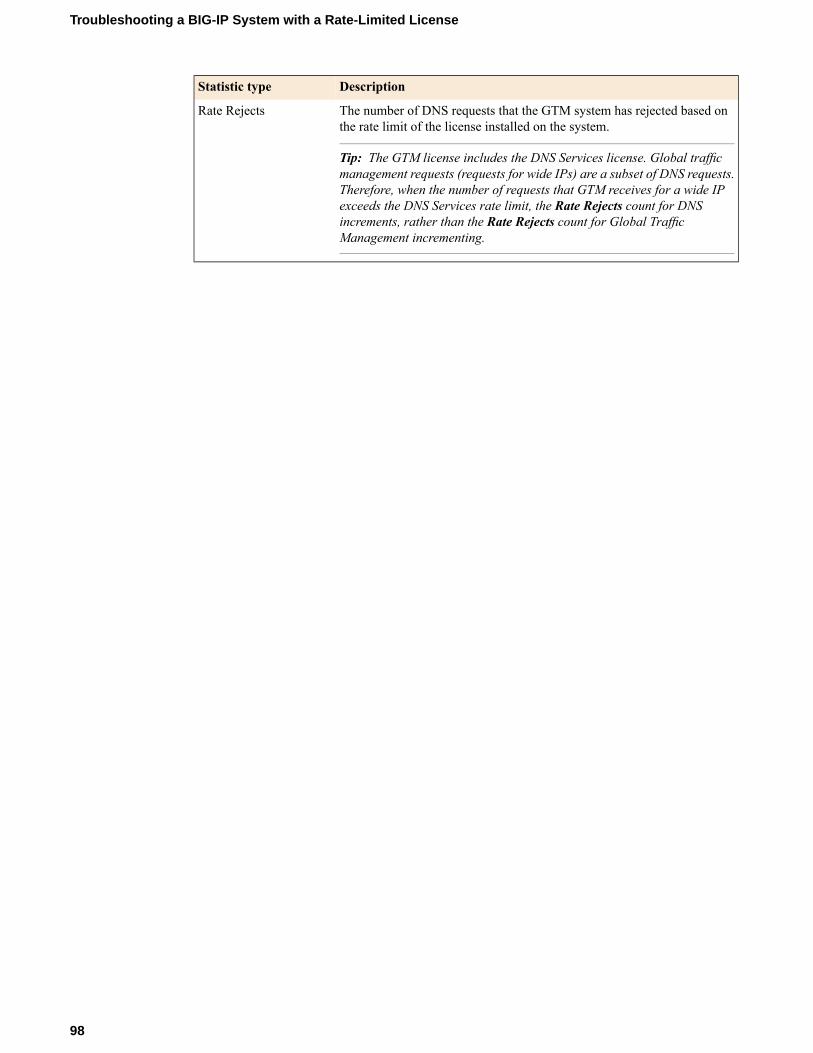
DescriptionStatistic type
The number of DNS requests that the GTM system has rejected based onthe rate limit of the license installed on the system.
Tip: The GTM license includes the DNS Services license. Global trafficmanagement requests (requests for wide IPs) are a subset of DNS requests.
Rate Rejects
Therefore, when the number of requests that GTM receives for a wide IPexceeds the DNS Services rate limit, the Rate Rejects count for DNSincrements, rather than the Rate Rejects count for Global TrafficManagement incrementing.
98
Troubleshooting a BIG-IP System with a Rate-Limited License
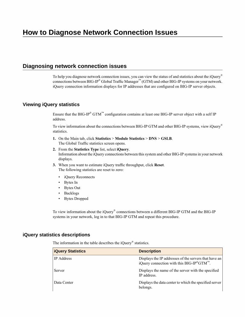
How to Diagnose Network Connection Issues
Diagnosing network connection issues
To help you diagnose network connection issues, you can view the status of and statistics about the iQuery®
connections between BIG-IP®Global TrafficManager™ (GTM) and other BIG-IP systems on your network.iQuery connection information displays for IP addresses that are configured on BIG-IP server objects.
Viewing iQuery statistics
Ensure that the BIG-IP® GTM™ configuration contains at least one BIG-IP server object with a self IPaddress.
To view information about the connections between BIG-IP GTM and other BIG-IP systems, view iQuery®
statistics.
1. On the Main tab, click Statistics >Module Statistics > DNS > GSLB.The Global Traffic statistics screen opens.
2. From the Statistics Type list, select iQuery.Information about the iQuery connections between this system and other BIG-IP systems in your networkdisplays.
3. When you want to estimate iQuery traffic throughput, click Reset.The following statistics are reset to zero:
• iQuery Reconnects• Bytes In• Bytes Out• Backlogs• Bytes Dropped
To view information about the iQuery® connections between a different BIG-IP GTM and the BIG-IPsystems in your network, log in to that BIG-IP GTM and repeat this procedure.
iQuery statistics descriptions
The information in the table describes the iQuery® statistics.
DescriptioniQuery Statistics
Displays the IP addresses of the servers that have aniQuery connection with this BIG-IP®GTM™.
IP Address
Displays the name of the server with the specifiedIP address.
Server
Displays the data center to which the specified serverbelongs.
Data Center
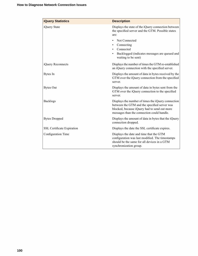
DescriptioniQuery Statistics
Displays the state of the iQuery connection betweenthe specified server and the GTM. Possible statesare:
iQuery State
• Not Connected• Connecting• Connected• Backlogged (indicates messages are queued and
waiting to be sent)
Displays the number of times the GTM re-establishedan iQuery connection with the specified server.
iQuery Reconnects
Displays the amount of data in bytes received by theGTM over the iQuery connection from the specifiedserver.
Bytes In
Displays the amount of data in bytes sent from theGTM over the iQuery connection to the specifiedserver.
Bytes Out
Displays the number of times the iQuery connectionbetween the GTM and the specified server was
Backlogs
blocked, because iQuery had to send out moremessages than the connection could handle.
Displays the amount of data in bytes that the iQueryconnection dropped.
Bytes Dropped
Displays the date the SSL certificate expires.SSL Certificate Expiration
Displays the date and time that the GTMconfiguration was last modified. The timestamps
Configuration Time
should be the same for all devices in a GTMsynchronization group.
100
How to Diagnose Network Connection Issues

Index
A
allow-transfer statementmodifying for zone transfers 38
APNand listeners 54and wide IPs 56
authenticationand SSL certificate chains 79and SSL certificates 75
authoritative name server, designating GTM 39authorizing BIG-IP communications 15automatic configuration save
changing the save interval 90disabling 90disabling using tmsh 90
automatic configuration save timeoutchanging 89
automatic saveabout 89configuring the save timeout 89
auto-saveconfiguring the save timeout 89
B
big3d_install script, running 19big3d agent
and iQuery 15and SSL certificates 75importing certificate chains 78importing root certificate 76upgrading 19
bigip_add utilityand integrating LTM with GTM 21running 24
BIG-IP communications 15BIG-IP LTM
and route domains 59and server definition 17, 23
BIG-IP systems, and iQuery connections 99Bridge mode, and global traffic management 44
C
canonical namesand pools 35
canonical names, and creating pools 35CA servers
and device certificates 77certificate chains
and SSL authentication 77creating 77verifying exchange 79
certificate exchange, verifying 77certificates
importing device 75, 77
CNAME recordand redirecting DNS queries 35
CNAME recordsabout 35
CNAME resolutionsviewing statistics about 36
configuration changesand configuring manual save 90
configuration files, acquiring 30configuration saves
and changing the save timeout 89configuration synchronization
enabling for GTM 73connection refused error
and listeners 40and TCP protocol 40
connectionsviewing iQuery statistics 99viewing status 99
custom GTP monitorsand GTP load balancing 55creating 55
D
data centersassigning Prober pools 87creating 28defining 16, 21, 52, 72, 85
delegated zonesand listeners 32creating on local DNS servers 32
deterministic probing, implementing 83device certificates
importing 75, 77signed by CA servers 75
disabling automatic configuration save 90disabling automatic save 90DNS queries
creating listeners to forward 44DNS queries for GTM
load balancing 19DNS server pools, and listeners 48DNS servers
and creating pools 48and GTM 43and pools 47and wide IPs 31configuring to allow zone transfers 38delegating wide IP requests 31identifying legacy 39modifying 39replacing with GTM 37
DNS Servicesabout rate-limited license statistics 97
DNS statisticsviewing per wide IP 36
101
Index

DNS trafficand GTM 43and statistics per wide IP 36and wide IPs 43creating listeners to identify 40forwarding 43identifying 32routing 43
E
effective rate limit (RPS)about rate-limited license statistics 97
enabling automatic save 90enabling manual save 90
F
file transfers, See zone transfers.forwarding traffic to DNS servers 43
G
global server load balancingand decision logs 93
global traffic managementand wildcard listeners 44load balancing to a pool of DNS servers 47
global traffic management, and Bridge mode 44GTM
about rate-limited license statistics 97and bigip_add utility 24integrating with LTM 21
gtm_add scriptand server status 28running 30using 74
gtmd agentand importing root certificates 76and SSL certificates 75importing certificate chains 78
gtmd agent, and iQuery 15GTM synchronization groups
about 27adding new GTM 27illustrated 27
GTP load balancingand custom GTP monitors 55
GTP monitorand packet gateways 51
H
high-speed remote logsand load-balancing decisions 93
hosts, defining 95
I
integrating with existing DNS servers 31integration of GTM with older systems 15
integration of LTM and GTM systems 21intelligent probing, about 83iQuery
and big3d agent 15and gtmd agent 15and statistics 99viewing statistics about connections 99viewing status of connections 99
iQuery connectionsand statistics 99and status 99
L
LDNS, creating delegated zones 32legacy DNS servers
and zone transfers 38identifying by self IP addresses on BIG-IP GTM 39
Level 1about SSL authentication 75
listenersabout wildcard 44and pools of DNS servers 48and refused connection error 40and TCP protocol 40and UDP protocol 40creating to forward DNS queries 44creating to handle wide IP traffic locally 32creating to identify APNs 54creating to identify DNS traffic 40, 72defined 31, 37, 43, 47
load balancing DNS queries for GTM 19load balancing process
about Prober pool status 84about traffic management capabilities 15and non-wide IP traffic 47and Prober pools 83
load balancing traffic to a pool of DNS servers 47local DNS servers, and replacing with GTM 37logging
enabling load-balancing decision logs for a wide IP 93logical network components
and creating wide IPs 40, 45logs, and Prober pool data 88LTM
and bigip_add utility 24and route domains 59, 65and server definition 17, 23integrating with GTM 21
M
manual saveconfiguring using tmsh 90enabling 90
N
negative DNS responses, and GTM 81network, deploying GTM for single route domain 59network connection issues, diagnosing 99network placement of GTM forwarding traffic 44
102
Index

network trafficlisteners 31, 37, 43, 47
NTP servers, defining 71
O
object countabout rate-limited license statistics 97
P
packet gatewaydefining 53
packet gatewaysand GTM monitoring 51
packet gateway systemsand creating a pool 56
placement of GTM on network to forward traffic 44pool
creating for packet gateway systems 56pools
and CNAME records 35and DNS servers 47–48creating 81creating with canonical name 35
primary servers, defining for zones 39Prober pools
about 83about statistics 84about status 84and data centers 87and deterministic probing 83and logs 88and servers 87and statistics 88creating 86
R
rate-limited DNS Services licenseand viewing statistics 97
rate-limited GTM licenseand viewing statistics 97
rate rejectsabout rate-limited license statistics 97
redirect using CNAME recordabout 35
redundant system configurationsand GTM 71defining servers 73
refused connection error 40replacing local DNS servers 37rollover, See emergency rollover. 71root certificates, importing 76root servers, and zones 39route domains
and GTM 59and LTM 59, 65and self IP addresses 61, 68and server definition 62, 68and VLANs 60, 67creating 60, 67
route domains (continued)deploying GTM on network with multiple route domains65
routing traffic to DNS servers 43
S
saving configuration changesabout 89and changing the save interval using tmsh 90and changing the save timeout 89and configuring manual save 90
scriptsrunning big3d_install script 19running gtm_add script 28
self IP addressesand route domains 68creating for route domains 61creating on GTM for legacy DNS servers 39
self-signed SSL certificates, about 75server
creating 85server pools, and listeners 48servers
assigning Prober pools 87defining BIG-IP LTM systems 17, 23defining for BIG-IP GTM 16, 22, 52defining for route domains 62, 68defining GTM redundant system configurations 73defining new BIG-IP GTM 28defining third-party host servers 95
single route domain, deploying GTM on network 59SNMP monitoring
and third-party host servers 95creating monitors 95
SOA recordsabout 81and wide IPs 81
SSL authenticationabout 75and certificate chains 79defined 75
SSL certificatesabout Level 1 SSL authentication 75about self-signed 75and big3d agent 76, 78and CA servers 75and certificate chain authentication 77and gtmd agent 76, 78and verifying chain exchange 79creating chains 77signed by third party 75verifying exchange 77
statisticsabout iQuery 99viewing for DNS traffic per wide IP 36viewing for Prober pools 88viewing per wide IP 36
statistics, and Prober pools 84status, and Prober pools 84synchronization
enabling 27
103
Index

synchronization (continued)enabling for GTM 73
synchronization groupsabout 27adding new GTM 27illustrated 27
T
TCP protocoland connection refused error 40and listeners 40
third-party servers, and SNMP monitoring 95traffic forwarding, placement of GTM 44
U
UDP protocol, and listeners 40
V
VLANscreating for a route domain on BIG-IP LTM 67
VLANs (continued)creating for route domains 60
W
wide IPsand DNS servers 31, 43and DNS traffic 32and load-balancing decision logs 93and pools configured with a CNAME 35and SOA records 81configuring for an APN 56creating 40, 45enabling load-balancing decision logging 93
wildcard listeners, defined 44
Z
zonesand GTM as primary server 39and root servers 39
zone transfersand configuring DNS servers 38and legacy DNS servers 38
104
Index