Embed Size (px)
Citation preview
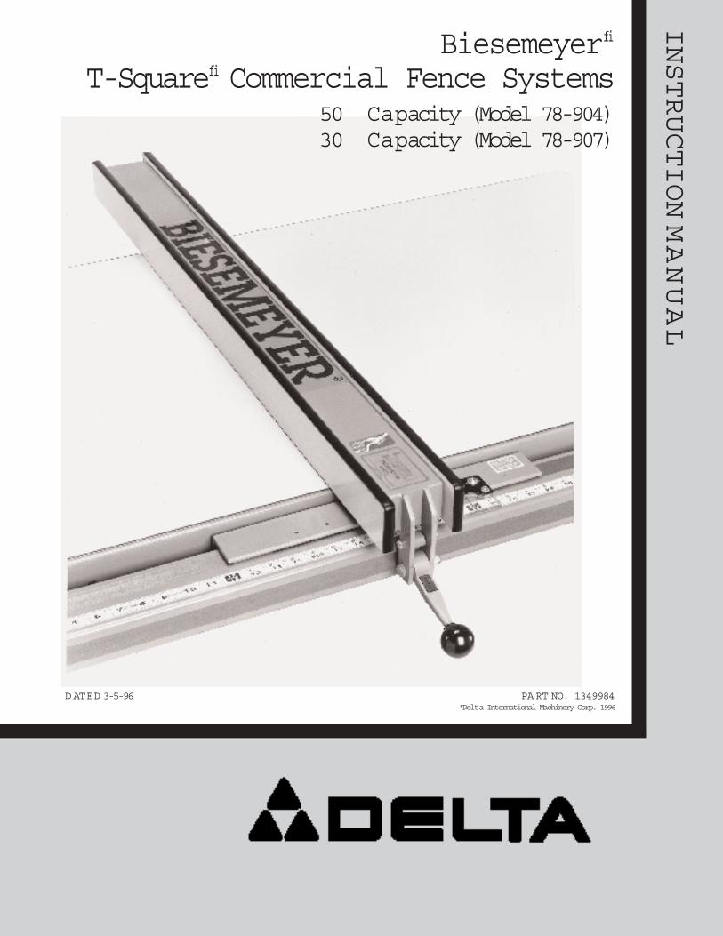
INSTRUCTIONMANUAL
D ATED 3-5-96 PA RT NO. 1349984'Delta International Machinery Corp. 1996
Biesemeyerfi
T-Squarefi Commercial Fence Systems50 Capacity (Model 78-904)30 Capacity (Model 78-907)

INTRODUCTIONThe 50 capacity (model 78-904) and 30 capacity (model 78-907) Biesemeyerfi T-Squarefi
Commercial fence systems are specially designed to be used with:
Delta 10 Tilting Arbor Unisawsfi
Delta 10 Tilting Arbor SawsDelta 10 Contractor sfi SawsDelta 10 Contractor sfi Saws II
The T-Squarefi Commercial Fence Systems include the fence assembly, front rail, rear rail andfront guide tube. The accessory right extension table (78-925 for 50 capacity model and 78-927for 30 capacity model) must be ordered separately or a similar extension table must be con-structed by following instructions in this manual. The accessory leg kit (model 78-952), usedto support the extension table, must also be ordered separately. IMPORTANT:The T-Squarefi
Fence System is designed to be used ONLY with a supporting extension table.
The following instructions illustrate assembling the T-Squarefi Commercial Fence System to aDelta 10 Tilting Arbor Unisawfi. Instructions for assembling the fence system to Delta 10 TiltingArbor Saws and 10 Contractor sfi Saws are identical unless otherwise noted.
UNPACKINGCarefully unpack the T-Squarefi fence system from the shipping carton(s). Figure 2 illustrates allthe items supplied with the 78-904 and 78-907 fence system.
1 -Rear Rail
2 -Front Rail
3 -Guide Tube
4 -T-Squarefi Fence Assembly
5 -Switch Adapter for Unisawsfi
6 -Switch Adapter for Contractor sfi Saws
7 -Cable Strap
8 -Template for aligning front rail to saw table
for fastening front and rear rails toright extension table
9 -1-1/2 long flat head Phillips screws (14)
10 -1-1/4 O.D. Flat Washers (14)
11 -1/4-20 hex nuts (14)
for fastening rear rail to saw table and sheet metalextension wing if applicable
12 -3/8-24 x 1-1/4 long hex head cap screws (3)
13 -7/8 O.D. flat washers (3)
14 -Lock washers (3)
15 -3/8-24 hex nuts (3)
for fastening front rail to saw table and sheet metalextension wing if applicable
16 -3/8-16 x 1-1/4 long flat head Phillips screws (3)
17 -7/8 O.D. flat washers (3)
18 -Lock washers (3)
19 -3/8-16 hex nuts (3)
for fastening guide tube to front rail
20 -1/2 long hex screws (7)
21 -Lock washers (7)
for fastening on-off switch adapter to guide tube whereapplicable on Unisawsfi or Contractorsfi Saws
22 -3/4 long hex head screws (2)
23 -Lock washers (2)
for fastening on-off switch to switch adapter whereapplicable on Contractor sfi Saws
24 - 3/8-16 x 1 long hex head screw (1)
25 -7/8 O.D. Flat washer (1)
27 -Hex nut (1)
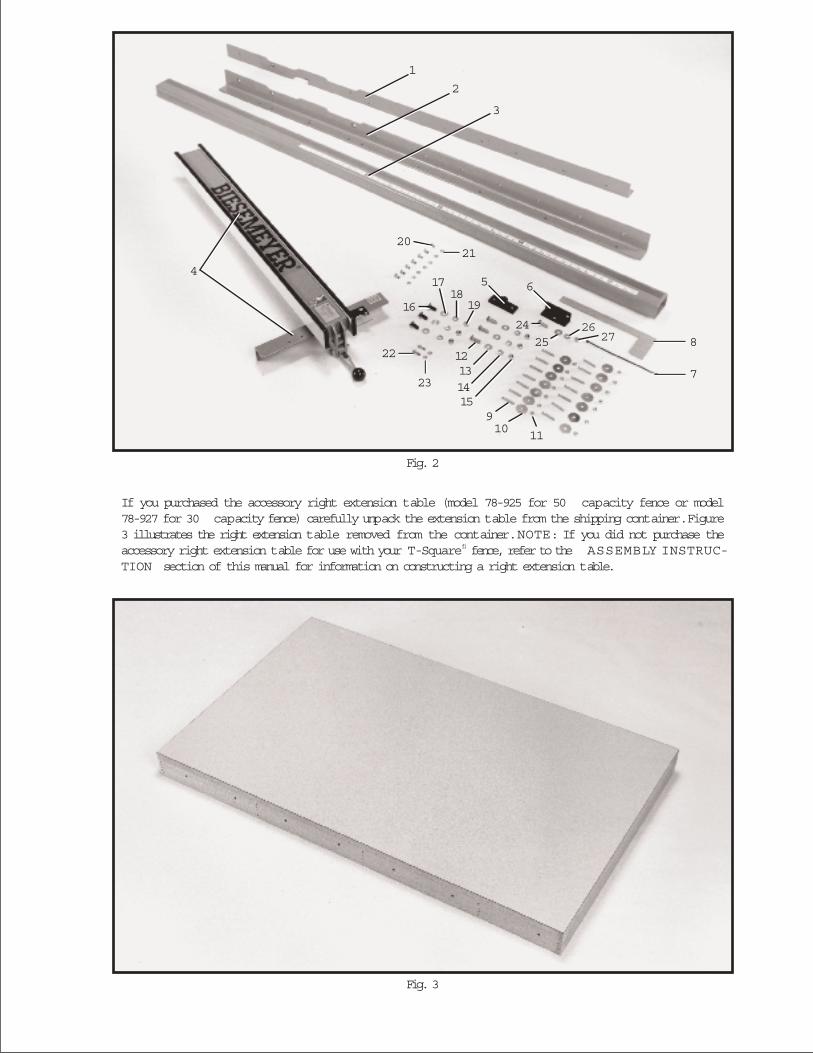
If you purchased the accessory right extension table (model 78-925 for 50 capacity fence or model78-927 for 30 capacity fence) carefully unpack the extension table from the shipping container.Figure3 illustrates the right extension table removed from the container. NOTE: If you did not purchase theaccessory right extension table for use with your T-Squarefi fence, refer to the ASSEMBLY INSTRUC-TION section of this manual for information on constructing a right extension table.
Fig. 2
Fig. 3
7
1
8
2
27
3
65
1110
26
9
2021
2425
16
17
22
23
1819
12131415
4
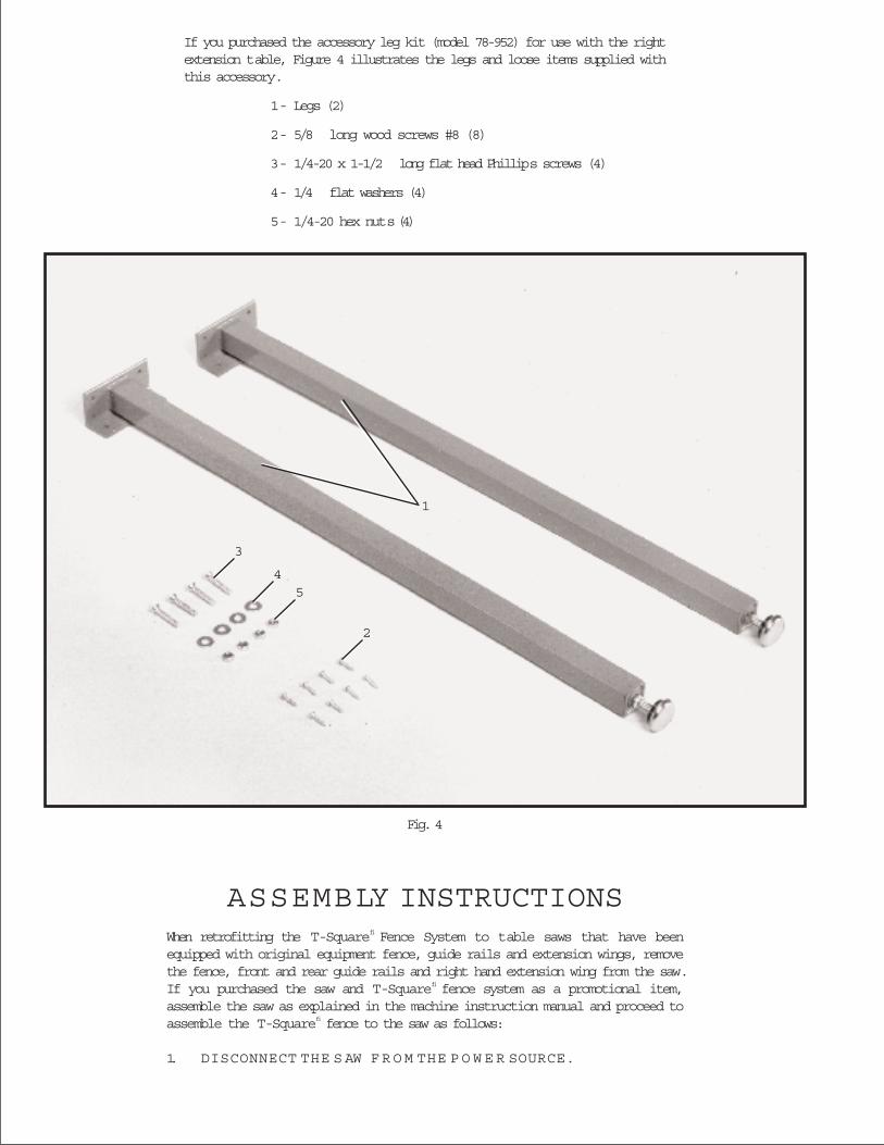
Fig. 4
If you purchased the accessory leg kit (model 78-952) for use with the rightextension table, Figure 4 illustrates the legs and loose items supplied withthis accessory.
1 - Legs (2)
2 - 5/8 long wood screws #8 (8)
3 - 1/4-20 x 1-1/2 long flat head Phillips screws (4)
4 - 1/4 flat washers (4)
5 - 1/4-20 hex nuts (4)
ASSEMBLY INSTRUCTIONSWhen retrofitting the T-Squarefi Fence System to table saws that have beenequipped with original equipment fence, guide rails and extension wings, removethe fence, front and rear guide rails and right hand extension wing from the saw.If you purchased the saw and T-Squarefi fence system as a promotional item,assemble the saw as explained in the machine instruction manual and proceed toassemble the T-Squarefi fence to the saw as follows:
1. DISCONNECT THE S AW F R O M THE P O W E R SOURCE.
3
45
2
1
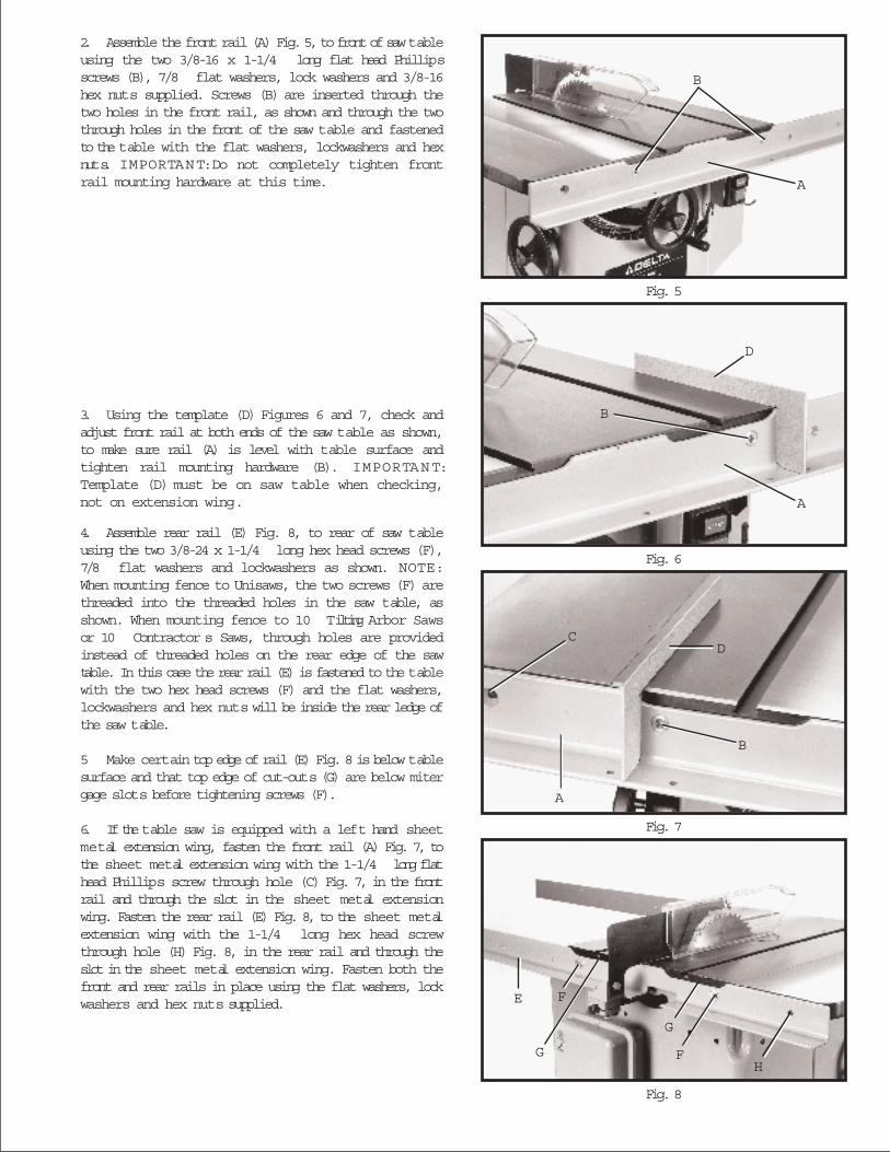
Fig. 5
Fig. 6
Fig. 7
Fig. 8
2. Assemble the front rail (A) Fig. 5, to front of saw tableusing the two 3/8-16 x 1-1/4 long flat head Phillipsscrews (B), 7/8 flat washers, lock washers and 3/8-16hex nuts supplied. Screws (B) are inserted through thetwo holes in the front rail, as shown and through the twothrough holes in the front of the saw table and fastenedto the table with the flat washers, lockwashers and hexnuts. IMPORTANT:Do not completely tighten frontrail mounting hardware at this time.
3. Using the template (D) Figures 6 and 7, check andadjust front rail at both ends of the saw table as shown,to make sure rail (A) is level with table surface andtighten rail mounting hardware (B). IMPORTANT:Template (D) must be on saw table when checking,not on extension wing.
4. Assemble rear rail (E) Fig. 8, to rear of saw tableusing the two 3/8-24 x 1-1/4 long hex head screws (F),7/8 flat washers and lockwashers as shown. NOTE:When mounting fence to Unisaws, the two screws (F) arethreaded into the threaded holes in the saw table, asshown. When mounting fence to 10 Tilting Arbor Sawsor 10 Contractor s Saws, through holes are providedinstead of threaded holes on the rear edge of the sawtable. In this case the rear rail (E) is fastened to the tablewith the two hex head screws (F) and the flat washers,lockwashers and hex nuts will be inside the rear ledge ofthe saw table.
5 Make certain top edge of rail (E) Fig. 8 is below tablesurface and that top edge of cut-outs (G) are below mitergage slots before tightening screws (F).
6. If the table saw is equipped with a left hand sheetmetal extension wing, fasten the front rail (A) Fig. 7, tothe sheet metal extension wing with the 1-1/4 long flathead Phillips screw through hole (C) Fig. 7, in the frontrail and through the slot in the sheet metal extensionwing. Fasten the rear rail (E) Fig. 8, to the sheet metalextension wing with the 1-1/4 long hex head screwthrough hole (H) Fig. 8, in the rear rail and through theslot in the sheet metal extension wing. Fasten both thefront and rear rails in place using the flat washers, lockwashers and hex nuts supplied.
A
B
A
B
D
C
A
B
D
E F
G
G
FH
6
Fig. 9
Fig. 10
Fig. 11
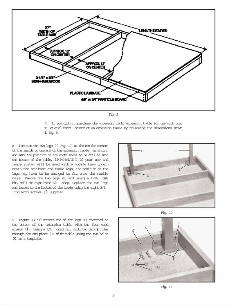
8. Position the two legs (H) Fig. 10, at the two far cornersof the inside of one end of the extension table, as shown,and mark the position of the eight holes to be drilled intothe bottom of the table. IMPORTANT:If your saw andfence system will be used with a mobile base under-neath the saw base and table legs, the position of thelegs may have to be changed to fit onto the mobilebase. Remove the two legs (H) and using a 1/16 drillbit, drill the eight holes 1/2 deep. Replace the two legsand fasten to the bottom of the table using the eight 3/4long wood screws (I) supplied.
9. Figure 11 illustrates one of the legs (H) fastened tothe bottom of the extension table with the four woodscrews (I). Using a 1/4 drill bit, drill two through holesthrough the end piece (J) of the table using the two holes(K) as a template.
7. If you did not purchase the accessory right extension table for use with yourT-Squarefi fence, construct an extension table by following the dimensions shownin Fig. 9.
H H
II
H
KK
IM
J
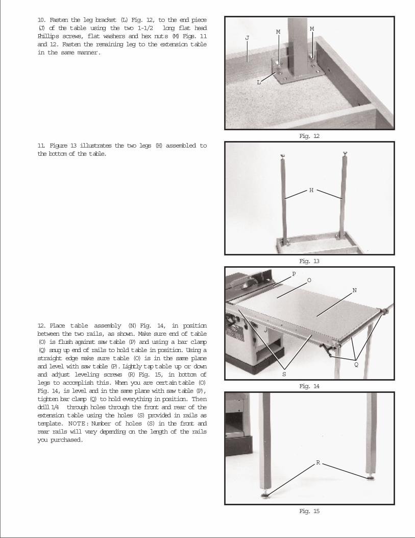
Fig. 12
Fig. 13
Fig. 14
Fig. 15
10. Fasten the leg bracket (L) Fig. 12, to the end piece(J) of the table using the two 1-1/2 long flat headPhillips screws, flat washers and hex nuts (M) Figs. 11and 12. Fasten the remaining leg to the extension tablein the same manner.
11. Figure 13 illustrates the two legs (H) assembled tothe bottom of the table.
12. Place table assembly (N) Fig. 14, in positionbetween the two rails, as shown. Make sure end of table(O) is flush against saw table (P) and using a bar clamp(Q) snug up end of rails to hold table in position. Using astraight edge make sure table (O) is in the same planeand level with saw table (P). Lightly tap table up or downand adjust leveling screws (R) Fig. 15, in bottom oflegs to accomplish this. When you are certain table (O)Fig. 14, is level and in the same plane with saw table (P),tighten bar clamp (Q) to hold everything in position. Thendrill 1/4 through holes through the front and rear of theextension table using the holes (S) provided in rails astemplate. NOTE: Number of holes (S) in the front andrear rails will vary depending on the length of the railsyou purchased.
J
L
M M
H
PO
N
S
Q
R
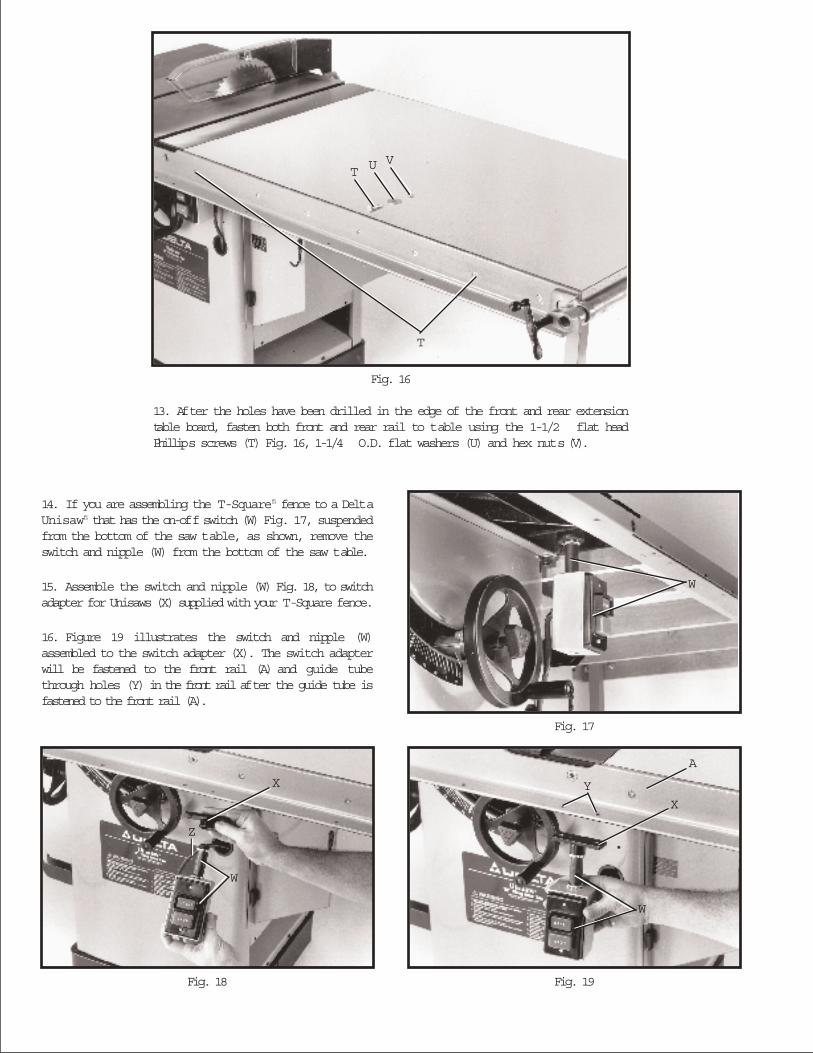
Fig. 17
Fig. 18 Fig. 19
16. Figure 19 illustrates the switch and nipple (W)assembled to the switch adapter (X). The switch adapterwill be fastened to the front rail (A) and guide tubethrough holes (Y) in the front rail after the guide tube isfastened to the front rail (A).
15. Assemble the switch and nipple (W) Fig. 18, to switchadapter for Unisaws (X) supplied with your T-Square fence.
14. If you are assembling the T-Squarefi fence to a DeltaUnisawfi that has the on-off switch (W) Fig. 17, suspendedfrom the bottom of the saw table, as shown, remove theswitch and nipple (W) from the bottom of the saw table.
13. After the holes have been drilled in the edge of the front and rear extensiontable board, fasten both front and rear rail to table using the 1-1/2 flat headPhillips screws (T) Fig. 16, 1-1/4 O.D. flat washers (U) and hex nuts (V).
Fig. 16
T
T U V
W
Z
X
W
Y
X
A
W
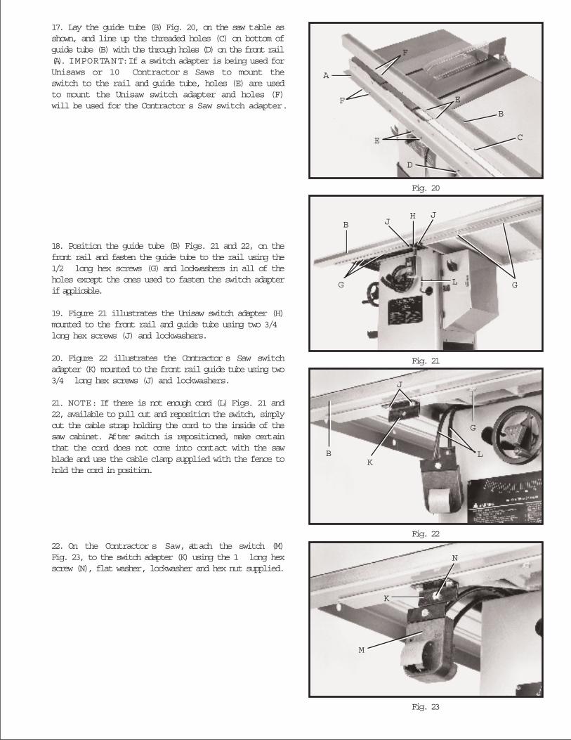
Fig. 20
Fig. 21
Fig. 22
Fig. 23
17. Lay the guide tube (B) Fig. 20, on the saw table asshown, and line up the threaded holes (C) on bottom ofguide tube (B) with the through holes (D) on the front rail(A). IMPORTANT:If a switch adapter is being used forUnisaws or 10 Contractor s Saws to mount theswitch to the rail and guide tube, holes (E) are usedto mount the Unisaw switch adapter and holes (F)will be used for the Contractor s Saw switch adapter.
22. On the Contractor s Saw, attach the switch (M)Fig. 23, to the switch adapter (K) using the 1 long hexscrew (N), flat washer, lockwasher and hex nut supplied.
18. Position the guide tube (B) Figs. 21 and 22, on thefront rail and fasten the guide tube to the rail using the1/2 long hex screws (G) and lockwashers in all of theholes except the ones used to fasten the switch adapterif applicable.
19. Figure 21 illustrates the Unisaw switch adapter (H)mounted to the front rail and guide tube using two 3/4long hex screws (J) and lockwashers.
20. Figure 22 illustrates the Contractor s Saw switchadapter (K) mounted to the front rail guide tube using two3/4 long hex screws (J) and lockwashers.
21. NOTE: If there is not enough cord (L) Figs. 21 and22, available to pull out and reposition the switch, simplycut the cable strap holding the cord to the inside of thesaw cabinet. After switch is repositioned, make certainthat the cord does not come into contact with the sawblade and use the cable clamp supplied with the fence tohold the cord in position.
A
B
C
D
F
F
E
E
B
G G
JJH
L
G
LK
B
J
N
K
M
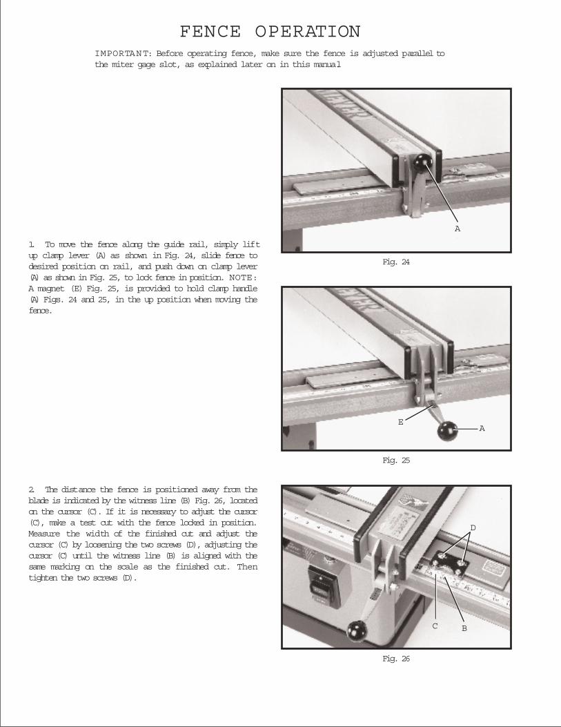
Fig. 24
Fig. 25
Fig. 26
FENCE OPERATIONIMPORTANT: Before operating fence, make sure the fence is adjusted parallel tothe miter gage slot, as explained later on in this manual.
1. To move the fence along the guide rail, simply liftup clamp lever (A) as shown in Fig. 24, slide fence todesired position on rail, and push down on clamp lever(A) as shown in Fig. 25, to lock fence in position. NOTE:A magnet (E) Fig. 25, is provided to hold clamp handle(A) Figs. 24 and 25, in the up position when moving thefence.
2. The distance the fence is positioned away from theblade is indicated by the witness line (B) Fig. 26, locatedon the cursor (C). If it is necessary to adjust the cursor(C), make a test cut with the fence locked in position.Measure the width of the finished cut and adjust thecursor (C) by loosening the two screws (D), adjusting thecursor (C) until the witness line (B) is aligned with thesame marking on the scale as the finished cut. Thentighten the two screws (D).
A
A
BC
D
E

Fig. 27
Fig. 28
Fig. 29
Fig. 30
ADJUSTING FENCEPARALLEL TOMITER GAGE SLOTSNOTE: Delta table saws have been aligned at the factoryso that the miter gage slots in the table are parallel withthe saw blade. It is recommended, however, to checkand make certain this alignment is correct before adjust-ing the fence parallel to the miter gage slot as follows:
The fence (A) Fig. 27, must be adjusted so it is parallel tothe miter gage slots (B). To check and adjust, movefence (A) until the bottom edge of the fence is in line withthe edge of one of the miter gage slots as shown, andpush down on the fence clamping lever (C). Check to seeif the fence (A) is parallel to the miter gage slot the entirelength of the table. If an adjustment must be made, lift upfence locking lever (C) and raise fence up off the guidetube, as shown in Fig. 28. Slightly tighten or loosen oneof the two adjusting screws (D) or (E) Fig. 28, using a3/16 allen wrench (F), not supplied. Replace the fenceon the guide tube and check again to see if the edge ofthe fence is parallel with the miter gage slot the entirelength of the slot. Repeat this adjustment until you aresure the fence is parallel with the miter gage slot.IMPORTANT:VERY LITTLE MOVEMENT O F SCREWS(D) A N D (E) IS N E C E S S A RY TO ADJUST T H EFENCE PARALLEL WITH THE MITER G A G E SLOT.
ADJUSTING CLAMPINGACTION OF FENCELOCKING HANDLEWhen the fence locking handle (A) is pushed to the downposition, as shown in Fig. 29, the fence assembly (B)should be completely clamped to the guide tube (C). Ifthe fence assembly (B) is not completely clamped to theguide tube (C) when the handle (A) is pushed down, asshown in Fig. 29, lift up handle (A) and raise fenceassembly (B) up off the guide tube (C). Slightly tightenthe two adjusting screws (D) and (E) Fig. 30, using the3/16 allen wrench (F) not supplied. Adjusting screws(D) and (E) Fig. 30, should be tightened an equalamount. Replace fence onto the guide tube and re-check to see if the fence assembly (B) Fig. 29, is com-pletely tightened to the guide tube (C) with the lockinghandle (A) pushed down. Adjust further if necessary.IMPORTANT:AFTER ADJUSTING THE CLAMPINGACTION O F THE FENCE LOCKING HANDLE, CHECKTO SEE IF THE FENCE IS PARALLEL TO THE MITERG A G E SLOT A N D ADJUST IF NECESSARY.
A
C
B
E
F
D
AC
B
FD
E
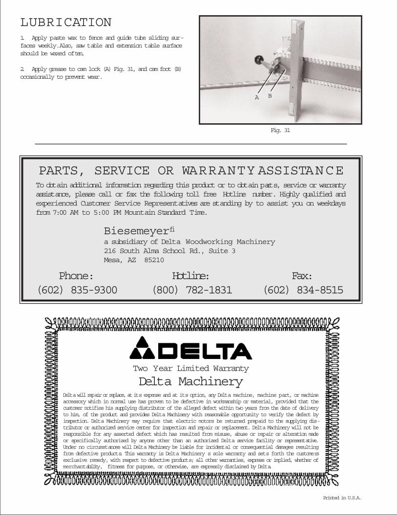
LUBRICATION1. Apply paste wax to fence and guide tube sliding sur-faces weekly. Also, saw table and extension table surfaceshould be waxed often.
2. Apply grease to cam lock (A) Fig. 31, and cam foot (B)occasionally to prevent wear.
Fig. 31
Delta will repair or replace, at its expense and at its option, any Delta machine, machine part, or machineaccessory which in normal use has proven to be defective in workmanship or material, provided that thecustomer notifies his supplying distributor of the alleged defect within two years from the date of deliveryto him, of the product and provides Delta Machinery with reasonable opportunity to verify the defect byinspection. Delta Machinery may require that electric motors be returned prepaid to the supplying dis-tributor or authorized service center for inspection and repair or replacement. Delta Machinery will not beresponsible for any asserted defect which has resulted from misuse, abuse or repair or alteration madeor specifically authorized by anyone other than an authorized Delta service facility or representative.Under no circumstances will Delta Machinery be liable for incidental or consequential damages resultingfrom defective products. This warranty is Delta Machinery s sole warranty and sets forth the customersexclusive remedy, with respect to defective products; all other warranties, express or implied, whether ofmerchantability, fitness for purpose, or otherwise, are expressly disclaimed by Delta.
Two Year Limited Warranty
Delta Machinery
Printed in U.S.A.
PARTS, SERVICE OR WARRANTY ASSISTANCETo obtain additional information regarding this product or to obtain parts, service or warrantyassistance, please call or fax the following toll free Hotline number. Highly qualified andexperienced Customer Service Representatives are standing by to assist you on weekdaysfrom 7:00 AM to 5:00 PM Mountain Standard Time.
Biesemeyerfia subsidiary of Delta Woodworking Machinery216 South Alma School Rd., Suite 3Mesa, AZ 85210
Phone: Hotline: Fax:(602) 835-9300 (800) 782-1831 (602) 834-8515
A B