Embed Size (px)
Citation preview

CITY OF REDMONDBICYCLE DESIGN MANUAL
Adopted August 24, 2016


ContentsIntroduction 1
Redmond’s Bicycle Plans and Manuals 1
How to Use this Manual 1
Cycle Track: One Way, In-Street Separation, Vertical Object 5
Cycle Track: One Way, In-Street, Curb Separated 6
Cycle Track: One Way, Raised 7
Cycle Track: Two Way, In-Street Separation, Vertical Object (no on-street parking) 8
Cycle Track: Two Way, In-Street Separation, Vertical Object (on-street parking present) 9
Cycle Track: Two Way, In-Street, Curb Separated (no on-street parking) 10
Cycle Track: Two Way, In-Street, Curb Separated (on-street parking present) 11
Cycle Track: Two Way, Raised 12
Shared Sidepath 13
Shared Use Path 14
Bicycle Lanes 15
Buffered Bicycle Lanes 16
Bike Climbing Lanes 17
Enhanced Bike Lane 18
Shared Lane Markings 19
Bicycle Boulevards 20
Bike Box 22
Intersection Markings 23
Combined Bike Lane/Right Turn Lane (right-turn pocket) 24
Through Bike Lane (trap lane) 25
Through Bike Lane (right turn pocket) 26
Combined Bike Lane/Right Turn Lane (on-street parking present) 27
Shared Right Turn Lane (Mixing Zone) 28
Through Bike Lane (on curb line) 29
Left Turn Bike Lane 30
Protected Intersection 31
Two-Stage Turn Queue (no parking lane) 32
Enhanced Driveway Crossing 33
Transition Ramp 34
Bicycle Signal (with lead interval) 36
Bicycle Detection 37
Right Turn on Red (RTOR) Restriction 38
Additional Design Treatments 39
Long-term Bicycle Parking Guidelines 40

City of Redmond Bicycle Design Manual | 1
IntroductionThe 2016 Bicycle Facility Design Manual is a design guide to be used to help engineer bicycle projects in Redmond. It is intended to help ensure consistent design of bicycle facilities and acts as a detailed supplement to national bicycle design guides such as those provided by AASHTO and NACTO.
This Manual replaces the August 2009 (updated March 2012) Bicycle Facilities Design Manual, Guidelines for the City of Redmond. This new version intends to build upon the success of the previous Manual, which unified bicycle lane and bicycle parking design.
A Major theme of this updated Manual is to incorporate new bicycle facilities that are being utilized around the country, such as cycle tracks and bicycle signals. The incorporation of these facilities is intended to help Redmond meet its goal of increasing bicycle ridership to meet Redmond’s 5 percent bicycle mode share goal (embedded in the Transportation Master Plan). Cities across the country have experienced significant increases in bicycle ridership by implementing bicycle facilities that:
• provide greater separation from vehicles,
• reduce the number of bicycle/vehicle intersection conflicts, or
• more clearly identify intersection conflicts and appropriate bicycle/vehicle positioning to help mitigate the conflict
Redmond’s Bicycle Plans and Manuals Bicycle planning and engineering work in Redmond is guided by three different documents:
• 2013 Transportation Master Plan
• Bicycle Strategic Plan (Anticipate completion in 2016)
• 2016 Bicycle Facilities Design Manual
The Transportation Master Plan sets the long range policy direction for bicycling, the Bicycle Strategic Plan sets the short term project funding direction, and the Bicycle Facilities Design Manual is used for design of bicycle facilities.
How to Use this Manual Many different bicycle facilities are included in this Manual, providing a menu of design treatments to be applied on corridors and at intersections. Varying widths are included in order to balance the need for quality facilities with the need to complete a connected bicycle network. Each facility type typically includes a diagram, notes, and standard, minimum, and maximum widths:
• standard widths – the typical facility width to be utilized during new facility construction. Additional width may be considered to increase bicyclist comfort.
• minimum retrofit widths – the minimum facility width that can be used in a retrofit project. However, where possible, additional bicycle facility width should be provided to improve bicycle comfort.

2 | City of Redmond Bicycle Design Manual
• maximum width – a maximum width has been identified for certain facilities when additional width allocated to the bicycle facility may reduce the safety or comfort of the bicycle facility.
As part of any project, it is important to design a continuous, quality bicycle facility on a corridor, including at intersections because bicyclist comfort is typically determined by the worst facility on a bicycle route. For example, a cycle track facility on a corridor that transitions to a shared lane at an intersection will not be a comfortable bicycle facility that increases bicycle ridership; it will be anticipated to have the low ridership that is seen on shared lane facilities.
Lastly, the Manual includes a section called Additional Design Treatments, which provides detail on treatments that are not specific corridor or intersection bicycle facilities. Items include bollards, detours, long term bicycle parking requirements and more.
When designing bicycle facilities please ensure review by the bicycle program coordinator. The current coordinator is Peter Dane (425.556.2816, [email protected]).

Corridor Facilities


City of Redmond Bicycle Design Manual | 5
Cycle Track: One Way, In-Street Separation, Vertical ObjectINTENT: High comfort achieved by lateral separation and vertical delineation using less permanent elements(e.g. flexible posts, planters).
Cycle Track: One Way, In-Street Separation, Vertical Object
STANDARDRETROFIT MINIMUMMAXIMUM
2'
N/A
BUFFER
5'-6"
N/A
BIKE LANE
5' 1'5'-6"
N/A
3'
N/A
BIKE LANE
3' 5'
BUFFER
10'-40' TYP SPACE BETWEENFLEXIBLE DELINEATORS
BIKE LANE MARKING PER MUTCD 9C.04
PARKING
NOTES
1) Flexible delineators should generally be placed within the center of the buffer, but may be offset to provide additional clearance from the vehicle travel lane while maintaining a minimum 6-inch clearance from the edge of bike lane. Where minimum clearances cannot be provided, a bike lane or buffered bike lane with enhanced edge line treatment should be considered.
2) Spacing of flexible delineators should:• be 10 to 15 feet when adjacent to parking lane• be 25 to 40 feet when adjacent to vehicle travel lane to allow vehicles to pull over for emergency vehicles . If flexible delineators are
spaced 40 feet or more raised pavement markings may be added every 20 feet in the buffer evenly spaced between delineators (also see Enhanced Bike Lane details).
• provide adequate space for emergency access, maintenance, and driveways
3) For uphill segments of one-way cycle tracks 6 feet 6 inches width is desirable as it provides sufficient width to account for the weaving effect that happens for cyclists traveling at very slow speeds and allows faster cyclists to pass slower cyclists.
4) For asphalt surfaces thermoplastic is to be used for both longitudinal and cross hatch markings of buffer. Epoxy-based markings should be used on concrete surfaces.
Drawing not to scale

6 | City of Redmond Bicycle Design Manual
Cycle Track: One Way, In-Street, Curb SeparatedINTENT: High comfort achieved by lateral and physical separation using a curb median.
Cycle Track: One Way, In-Street, Curb Separated
STANDARDRETROFIT MINIMUMMAXIMUM
2'
N/A
CURBBUFFER
6'-6"
BIKE LANE
5'-6" 1'-6"6'-6"3'
N/A
BIKE LANE
3' 5'-6"
CURBBUFFER
BIKE LANE MARKING PER MUTCD 9C.04
N/A N/A
PARKING
NOTES
1) For downhill segments of 1-way curb separated cycle tracks it may be appropriate to provide exit opportunities at intersections near the top of a steep grade to allow higher-speed bicyclists to exit the cycle track and safely enter the nearest general purpose lane.
2) For uphill segments of one-way cycle tracks 6 feet 6 inches width is desirable as it provides sufficient width to account for the weaving effect that happens for cyclists traveling at very slow speeds and allows faster cyclists to pass slower cyclists.
3) Flexible delineators or other retroreflective vertical objects may be placed on center within the curb median in order to raise bicyclist and motorist awareness of its presence.
4) A C-curb or surface-mounted curb system (e.g. rubber curb, Quick Kurb) may be used as a lower cost curb buffer option.
Drawing not to scale

City of Redmond Bicycle Design Manual | 7
Cycle Track: One Way, RaisedINTENT: High comfort achieved by lateral and vertical separation.
Cycle Track: One Way, Raised
STANDARDRETROFIT MINIMUMMAXIMUM
4'2'N/A
6'-6"5'N/A
BIKELANE
STREETBUFFER
BIKE LANE MARKINGPER MUTCD 9C.04
NOTES
1) The buffer may consist of a landscape strip, or in more urbanized areas, a hardscaped furnishing zone. Lights, signage and trees may be placed within the buffer consistent with other City standards. A minimum 1-foot clearance should be provided between the edge of cycle track and any object placed within the buffer.
2) For uphill segments of one-way cycle tracks 6 feet 6 inches width is desirable as it provides sufficient width to account for the weaving effect that happens for cyclists traveling at very slow speeds and allows faster cyclists to pass slower cyclists.
3) The cycle track may be differentiated from the adjacent sidewalk using materials (e.g., asphalt vs. concrete) and/or incorporating a buffer that may consist of a change in grade (e.g. a 2-3 inch sloped curb) or physical elements such as landscaping or street furniture.
4) Fire requirements result in minimum 5’ street buffer when fire hydrants are placed in the street buffer.
Drawing not to scale

8 | City of Redmond Bicycle Design Manual
Cycle Track: Two Way, In-Street Separation, Vertical Object (no on-street parking)INTENT: High comfort achieved by lateral separation and vertical delineation using less permanent elements(e.g. flexible posts, planters).
Cycle Track: Two Way, In-Street Separation, Vertical Object(no parking)
CYCLE TRACK
STANDARDRETROFIT MINIMUMMAXIMUM
11'-6"9'-6"N/A
3'2'N/A
BUFFER
10'-40' TYP SPACE BETWEENFLEXIBLE DELINEATORS
BIKE LANE MARKINGPER MUTCD 9C.04
NOTES
1) Flexible delineators should generally be placed within the center of the buffer, but may be offset to provide additional clearance from the vehicle travel lane while maintaining a minimum 6-inch clearance from the edge of bike lane. Where minimum clearances cannot be provided, a bike lane or buffered bike lane with enhanced edge line treatment should be considered.
2) Spacing of flexible delineators should:• be 25 to 40 feet when adjacent to vehicle travel lane to allow vehicles to pull over for emergency vehicles . If flexible delineators are
spaced 40 feet or more raised pavement markings may be added every 20 feet in the buffer evenly spaced between delineators (also see Enhanced Bike Lane details).
• provide adequate space for emergency access, maintenance, and driveways
3) Additional cycle track width should be considered on streets with sustained grades of 5 percent or greater and where the volume of bicyclists in each direction exceeds, or is expected to exceed 150 per hour to allow for in-lane passing of slower uphill cyclists.
4) Solid center line striping should be provided for at least 20 feet approaching each side of an intersection and should be considered at locations where sight distance is limited.
5) For asphalt surfaces thermoplastic is to be used for both longitudinal and cross hatch markings of buffer. Epoxy-based markings should be used on concrete surfaces.
Drawing not to scale

City of Redmond Bicycle Design Manual | 9
Cycle Track: Two Way, In-Street Separation, Vertical Object (on-street parking present)INTENT: High comfort achieved by physical separation using less permanent elements(e.g. flexible posts, planters).
Cycle Track: Two Way, In-Street Separation, Vertical Object(parking)
CYCLE TRACK
STANDARDRETROFIT MINIMUMMAXIMUM
11'-6"9'-6"N/A
3'3'N/A
BUFFER
10'-40' TYP SPACE BETWEENFLEXIBLE DELINEATORS
BIKE LANE MARKINGPER MUTCD 9C.04
PARKING
NOTES
1) Flexible delineators should generally be placed within the center of the buffer, but may be offset to provide additional clearance from the vehicle travel lane while maintaining a minimum 6-inch clearance from the edge of bike lane. Where minimum clearances cannot be provided, a bike lane or buffered bike lane with enhanced edge line treatment should be considered.
2) Spacing of flexible delineators should:• 10 to 15 feet adjacent to parking• provide adequate space for emergency access, maintenance, and driveways
3) Additional cycle track width should be considered on streets with sustained grades of 5 percent or greater and where the volume of bicyclists in each direction exceeds, or is expected to exceed 150 per hour to allow for in-lane passing of slower uphill cyclists.
4) Solid center line striping should be provided for at least 20 feet approaching each side of an intersection and should be considered at locations where sight distance is limited.
5) For asphalt surfaces thermoplastic is to be used for both longitudinal and cross hatch markings of buffer. Epoxy-based markings should be used on concrete surfaces.
Drawing not to scale

10 | City of Redmond Bicycle Design Manual
Cycle Track: Two Way, In-Street, Curb Separated (no on-street parking)INTENT: High comfort achieved by lateral and physical separation using a curb median.
Cycle Track: Two Way, In-Street, Curb Separation(no parking)
CYCLE TRACK
STANDARDRETROFIT MINIMUMMAXIMUM
11'-6"9'-6"N/A
2'1'-6"N/A
BIKE LANE MARKINGPER MUTCD 9C.04
CURBBUFFER
NOTES
1) Additional cycle track width should be considered on streets with sustained grades of 5 percent or greater and where the volume of bicyclists in each direction exceeds, or is expected to exceed 150 per hour to allow for in-lane passing of slower uphill cyclists.
2) Solid center line striping should be provided for at least 20 feet approaching each side of an intersection and should be considered at locations where sight distance is limited.
3) A C-curb or surface-mounted curb system (e.g. rubber curb, Quick Kurb) may be used as a lower cost curb buffer option.
Drawing not to scale

City of Redmond Bicycle Design Manual | 11
Cycle Track: Two Way, In-Street, Curb Separated (on-street parking present)INTENT: High comfort achieved by lateral and physical separation using a curb median.
Cycle Track: Two Way, In-Street, Curb Separation(parking)
CYCLE TRACK
STANDARDRETROFIT MINIMUMMAXIMUM
11'-6"9'-6"N/A
3'3'N/A
BIKE LANE MARKINGPER MUTCD 9C.04
CURBBUFFER
PARKING
NOTES
1) Additional cycle track width should be considered on streets with sustained grades of 5 percent or greater and where the volume of bicyclists in each direction exceeds, or is expected to exceed 150 per hour to allow for in-lane passing of slower uphill cyclists.
2) Solid center line striping should be provided for at least 20 feet approaching each side of an intersection and should be considered at locations where sight distance is limited.
Drawing not to scale

12 | City of Redmond Bicycle Design Manual
Cycle Track: Two Way, RaisedINTENT: High comfort achieved by lateral and vertical separation.
Cycle Track: Two Way, Raised
CYCLE TRACK
STANDARDRETROFIT MINIMUMMAXIMUM
10'8'N/A
4'3'N/A
STREETBUFFER
BIKE LANE MARKINGPER MUTCD 9C.04
PARKING
NOTES
1) The street buffer may consist of a landscape strip, or in more urbanized areas, a hardscaped furnishing zone. Lights, signage and trees may be placed within the buffer consistent with other City standards. A minimum 1-foot clearance should be provided between the edge of cycle track and any object placed within the buffer.
2) The cycle track may be differentiated from the adjacent sidewalk using materials (e.g., asphalt vs. concrete) and/or incorporating a buffer that may consist of a change in grade (e.g. a 2-3 inch sloped curb) or physical elements such as landscaping or street furniture.
3) Fire requirements result in minimum 5’ street buffer when fire hydrants are placed in the street buffer.
Drawing not to scale

City of Redmond Bicycle Design Manual | 13
Shared SidepathINTENT: High comfort facility within street right-of-way shared by bicyclists and pedestrians.
Shared Sidepath
STANDARDRETROFIT MINIMUMMAXIMUM
4'3'N/A
12'10'
2'2'N/A
SHAREDSIDEPATH
N/A
STREETBUFFER
SIDEPATHBUFFER
NOTES
1) A minimum 2-foot setback should be provided between the edge of path and vertical objects.
2) The sidepath buffer width should accommodate adjacent land uses and provide adequate widths to access buildings or facilities.
3) Path width may be narrowed to 8 feet in short, constricted segments such as a bridge.
4) A “Path Narrows” sign should be used in situations where the path width is narrowed by 2 feet or more mid segment along the facility length.
5) Fire requirements result in minimum 5’ street buffer when fire hydrants are placed in the street buffer.
Drawing not to scale

14 | City of Redmond Bicycle Design Manual
Shared Use PathINTENT: High comfort facility within independent right-of-way shared by bicyclists and pedestrians.
Shared Use Path
BUFFER
STANDARDRETROFIT MINIMUMMAXIMUM
12'10'N/A
2'2'
BUFFER
2'2'
PATH
N/A N/A
NOTES
1) A minimum 2-foot setback should be provided between the edge of path and vertical objects.
2) Path width may be narrowed to 8 feet in short, constricted segments such as a bridge.
3) A “Path Narrows” sign should be used in situations where the path width is narrowed by 2 feet or more mid segment.
Drawing not to scale

City of Redmond Bicycle Design Manual | 15
Bicycle LanesINTENT: Low to medium comfort achieved through dedicated space.
Bicycle Lane
STANDARDRETROFIT MINIMUMMAXIMUM
5'-6"
BIKE LANE
5'-6"5'-6"7'
BIKE LANE
5'-6"7'
BIKE LANE MARKINGPER MUTCD 9C.04
PARKING
NOTES
1) Consider wider bike lanes where vehicle speeds are high, there are a high volume of large vehicles or there is a sustained grade greater than 5 percent.
2) Along sections of roadway with curb and gutter, a minimum usable surface (i.e., excluding gutter) width of 4’ measured from the longitudinal joint to the center of the bike lane line should be provided. Where gutters and parking are not present, the minimum bike lane width may be reduced to 4 feet.
3) Bike lane/parking lane design should take into account factors such as parking turnover, expected vehicle types and street grade:• If parking lane is less than 8 feet, then the minimum bicycle lane width should be 6 feet.• Where space permits, wider parking lanes (up to 9 feet max., except in truck loading zone) should be provided next to bike lanes
to give cyclists more buffer from opening car doors.
Drawing not to scale
(See note 2)

16 | City of Redmond Bicycle Design Manual
Buffered Bicycle LanesINTENT: Medium comfort achieved through dedicated space and lateral separation .
Buffered Bicycle Lane
STANDARDRETROFIT MINIMUMMAXIMUM
2'1'4'
BUFFER
6'5'7'
BIKE LANE
3'1'-6"4'
BUFFER
6'5'7'
BIKE LANE
BIKE LANE MARKINGPER MUTCD 9C.04
PARKING
NOTES
1) The preferred location of the buffer is between the travel lane and bicycle lane. The buffer may be placed between the bike lane and parking lane where parking turnover is high or on extended downhill segments where bicyclist speeds can be expected to be higher than normal.
2) Raised pavement markings may be added every 20 feet in the buffer (see Enhanced Bike Lane details).
3) For asphalt surfaces thermoplastic is to be used for both longitudinal and cross hatch markings of buffer. Epoxy-based markings should be used on concrete surfaces.
Drawing not to scale

City of Redmond Bicycle Design Manual | 17
Bike Climbing LanesINTENT: Low to medium comfort achieved through dedicated space in uphill direction.
Bike Climbing Lanes
STANDARDRETROFIT MINIMUMMAXIMUM
BIKE LANE
7'5'-6"6'-6"
BIKE LANE MARKINGPER MUTCD 9C.04
SHARED LANE MARKINGPER MUTCD 9C.07
PARKINGPARKING
NOTES
1) The retrofit minimum dimension should not be used in climbing lane segments where parking turnover is high or where there are frequently high volumes (existing or anticipated) of bicyclists to allow for in-lane passing of slower bicyclists.
2) A downhill bicycle lane should be provided when grades are less than 8 percent and no on-street parking is present.
Drawing not to scale

18 | City of Redmond Bicycle Design Manual
Enhanced Bike LaneINTENT: Medium comfort achieved through dedicated space and enhanced edge line treatment.
NOTES
1) Raised Pavement Markings (RPMs) should be placed:
a. Standard Bicycle Lane: on the bicycle lane stripe
b. Buffered Bicycle Lane: 4” offset from the outside of the buffer
2) RPMs should be spaced at:
a. On-street parking: every 40’
b. No on-street parking: every 20’
3) WSDOT Type 2W RPMs should be used in all locations
ENHANCED EDGE LINE TREATMENT
TYPE 2W RPM
TYPE 2W RPM
BUFFEREDBICYCLE LANE
STANDARDBICYCLE LANE
20'
20'
Drawing not to scale

City of Redmond Bicycle Design Manual | 19
Shared Lane MarkingsINTENT: Low comfort treatment used to indicate a shared lane environment for bicycles and motor vehicles.
Shared Lane Markings
4' MIN. 11' MIN.
SHARED LANE MARKINGPER MUTCD 9C.07
PARKING
NOTES
1) The use of shared lane markings on arterial streets should be reserved for short (less than 500 feet) highly constrained conditions where a high or medium comfort facility is not feasible as a means to guide bicyclists towards optimal positioning.
2) Shared lane markings may be placed a minimum 2.5 feet from the curb within shared lanes that are 14 feet in width or greater where there is no on-street parking.
3) On downhill segments (grades 5% or greater) the shared lane marking should be placed in the center of the lane.
Drawing not to scale

20 | City of Redmond Bicycle Design Manual
Bicycle BoulevardsINTENT: High comfort bicycle facility on low-volume, low speed local street, safe arterial crossings
Locations
Local (non-arterial) streets with less than 3,000 vehicles per day and posted speeds of 20 mph that provide continuous routes between destinations.
Design Elements
The target speed for bicycle boulevards is 20 mph. Include Neighborhood Traffic Calming approach in design.
Speed Humps
• Recommended placement to achieve target speed: approximately one every 300 feet OR one per block, whichever is greater
• Preferably placed at least 20 feet away from driveways and 100’ from intersections
• Along roads with slope between 5% and 8%, speed humps should have a center cut-through for bicyclists traveling downhill. Speed humps should not be installed along roads with grades over 8%.
• Along non-arterial emergency routes, speed cushions should be installed, in lieu of speed humps. Coordinate with the Fire Department.
• Should be adequately illuminated.
• Community outreach by the City’s Neighborhood Traffic Calming Program will be conducted before determining if speeds humps should be installed.
Arterial Intersection Improvement Alternatives
• High visibility integrated crosswalks with ADA-compliant curb ramps.
• Intersection treatments such as bike boxes (if a signalized intersection), advanced stop line, curb extensions, raised intersections or crossings, diverter islands, and median/refuge islands
• Appropriate intersection controls such as all-way stops, active warning signals, pedestrian hybrid beacon, and full signals will be determined by the City using best available safety research.
Signs
• Regulatory signs (e.g., 20 mph speed limit signs, stop signs)
• Warning signs (e.g., speed hump ahead, pedestrian crossing warning signs)
• Wayfinding signs
• Special street name signs (optional)
Pavement markings
• Install shared lane markings on either side of intersections with arterials, on the far side of intersections with non-arterials, and every 250 feet on mid-block segments
• Where a bicycle boulevard route turns at an intersection, modified shared lane markings may be installed within 50 feet of the intersection approach, and within the intersection itself to clearly indicate the route.
Lighting
• Standard roadway lighting is sufficient.

Intersection Geometric Treatments

22 | City of Redmond Bicycle Design Manual
Bike BoxINTENT: Exclusive queuing space and positioning guidance for bikes at signalized intersections to provide head start and reduce turning conflict with turning motorists
BIKE BOX
2' STANDARD(1' MIN, 4' MAX)
10' MIN.
2' TYP.
NOTES
1) Bike box may be extended across left-turn lane if there is a left-turn signal and a single general purpose lane to facilitate bicyclist left-turn movements. Alternatively, this treatment may be paired with a two-stage left turn box when there is an intersecting bicycle facility or destination that bicyclists are likely going to want to connect with.
2) Right Turn on Red restriction is typically used in order to prevent vehicle encroachment into the bike box and reduce conflicts between bicyclists and right-turning vehicles. In locations with high right turn volumes, an active display may be used to further alert motorists of the restriction.
3) Supplemental signage (as shown below) that indicates to motorists where they should stop in relation to the bike box is recommended, particularly for initial installations.
4) Utilities within the painted bike box area should not be painted.
Drawing not to scale

City of Redmond Bicycle Design Manual | 23
Intersection MarkingsINTENT: Provide positioning guidance for bicyclists and motorists through intersections and intersection approaches and raise motorist awareness of bicycle facility.
INTERSECTION MARKINGS FOR BICYCLE FACILITIES
2'
Match LeadingFacility Width
6" Wide DottedWhite Line
2'-6'
INTERSECTION / CONFLICT ZONEMARKING (OPT. 1)
CONFLICT ZONEAPPROACH MARKING
Bicycle LaneMarking (MUTCD9C.04)
Match LeadingFacility Width
6" Wide DottedWhite Line
Bicycle Lane Marking(MUTCD 9C.04)
Match LeadingFacility Width
2'
2'-6'
INTERSECTION / CONFLICT ZONEMARKING (OPT. 2)
NOTES
1) Intersection/Conflict Zone Marking: should be used where upstream and downstream bicycle facilities are present (except shared lane markings), including through a) bicycle/vehicle merge zones to raise awareness of potential conflict area, b) intersections where vehicle and bicycle positioning issues have been identified or are anticipated (e.g. skewed intersections), and c) driveways. Green markings and bicycle symbol are optional.
2) Conflict Zone Approach Marking: may be used at locations upstream of conflict zones where intersection/conflict zone markings are used. Conflict zone approach markings provide advance warning of conflict to motorists and bicyclists.
3) When bicycle lanes are dropped immediately upstream or downstream of an intersection, shared lane markings should be used to provide positioning guidance to bicyclists and alert motorists to expect bicyclists. Shared lane markings may be placed on a green background to further raise awareness of the shared lane.
4) Green pavement marking shall be thermoplastic material.
24 | City of Redmond Bicycle Design Manual
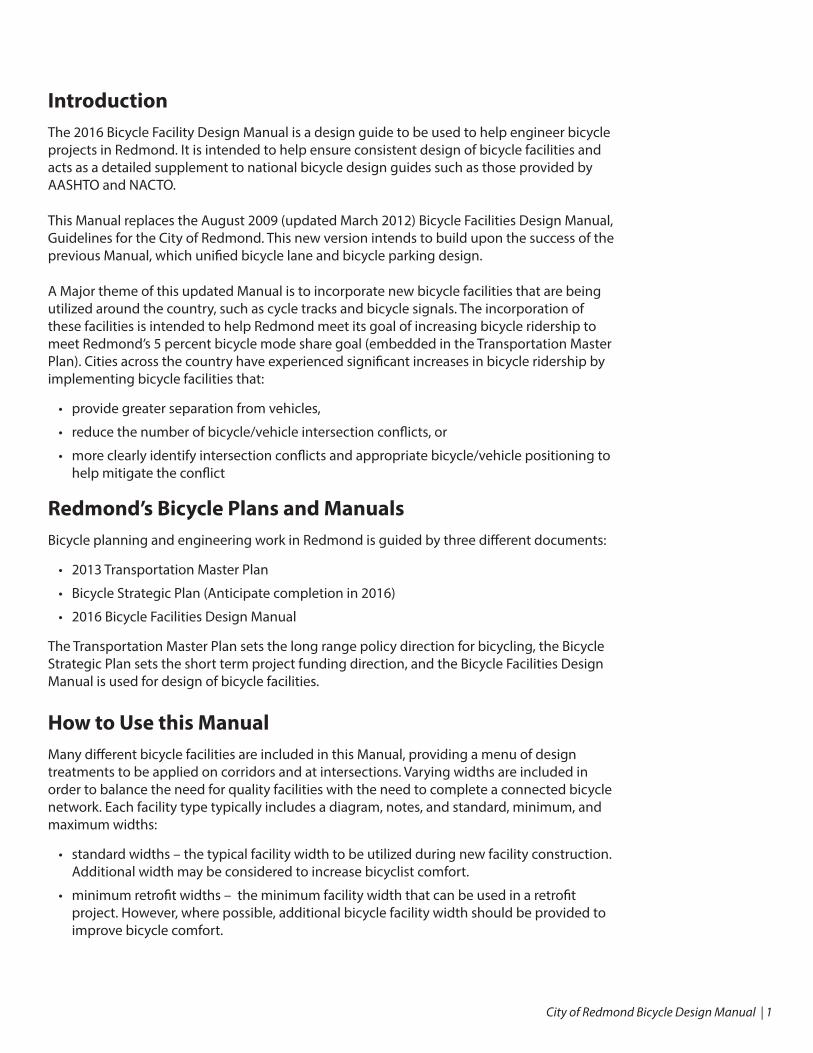
Combined Bike Lane/Right Turn Lane (right-turn pocket)INTENT: Low comfort facility that indicates intended path and optimal positioning for through bicyclists
COMBINED BIKE LANE/RIGHT TURN LANE
13'11'13'
STANDARDRETROFIT MINIMUMMAXIMUM
50' M
IN60
' (30
MP
H O
R L
ES
S)
90' (
>30
MP
H)
SHARED LANE
4'
6" WIDEDOTTEDWHITE LINE
100'
TY
P.
(NO
T TO
SC
ALE
)
NOTES
1) Minimizing the merge distance creates a discrete point of crossing that allows both bicycle riders and drivers to readily identify the crossing zone, improving the predictability and safety of the merge. When determining the appropriate merge area length, the designer should take into account vehicle speed and volume, turn queue lengths, presence of driveways, and available space in the roadway.
2) BEGIN RIGHT TURN (arrow) YIELD TO BIKES (R4-4) sign may be located at the beginning of the merge area.
Drawing not to scale

City of Redmond Bicycle Design Manual | 25
Through Bike Lane (trap lane)INTENT: Low comfort facility that indicates intended path and optimal positioning for through bicyclists
THROUGH BIKE LANE
5'4'6'-6"
BIKE LANE
STANDARDRETROFIT MINIMUMMAXIMUM
TURN LANE
60'
50' M
IN
GREEN PAINTOPTIONAL
BIKELANE
NOTES
1) Shared lane markings should be installed to indicate the shared lane and guide bicyclists towards the through bike lane. At a minimum markings should be placed where the bike lane ends and on the left side of the shared lane, in alignment with the through bike lane. An additional marking(s) may be placed in center of shared lane. Depending on the length of the merge area additional markings should be used as needed to maintain a maximum spacing between markings of 30 feet.
Drawing not to scale

26 | City of Redmond Bicycle Design Manual
Through Bike Lane (right turn pocket)INTENT: Medium comfort facility that provides exclusive space and positioning guidance for bikes and defined transition area for right-turning vehicles at intersection approaches
THROUGH BIKE LANE
5'4'6'-6"
STANDARDRETROFIT MINIMUMMAXIMUM
50' M
IN
BIKE LANE
60' (
30 M
PH
OR
LE
SS
)90
' (>3
0 M
PH
)
TRAVEL LANE
6" WIDEDOTTEDWHITE LINE
100'
TY
P.
(NO
T TO
SC
ALE
)
BIKELANE
NOTES
1) Minimizing the merge distance creates a discrete point of crossing that allows both bicycle riders and drivers to readily identify the crossing zone, improving the predictability and safety of the merge. When determining the appropriate merge area length, the designer should take into account vehicle speed and volume, turn queue lengths, presence of driveways, and available space in the roadway.
2) Solid green pavement markings or green background to the bike lane symbol may be used in portion of bike lane within right turn queue area where vehicle merging is not desired and bicyclists are expected to queue.
3) BEGIN RIGHT TURN (arrow) YIELD TO BIKES (R4-4) sign may be located at the beginning of the merge area.
Drawing not to scale

City of Redmond Bicycle Design Manual | 27
Combined Bike Lane/Right Turn Lane (on-street parking present)INTENT: Low comfort facility that indicates intended path and optimal positioning for through bicyclists
COMBINED BIKE LANE/RIGHT TURN LANE
50' M
IN60
' (30
MP
H O
R L
ES
S)
90' (
>30
MP
H)
20' M
INFO
R V
ISIB
ILIT
Y
BUFFER
SHARED LANE
3'1'N/A
13'11'13'
4'
STANDARDRETROFIT MINIMUMMAXIMUM
6" WIDE DOTTEDWHITE LINE
BUF. LANE
NOTES
1) Minimizing the merge distance creates a discrete point of crossing that allows both bicycle riders and drivers to readily identify the crossing zone, improving the predictability and safety of the merge. When determining the appropriate merge area length, the designer should take into account vehicle speed and volume, turn queue lengths, presence of driveways, and available space in the roadway.
2) Solid green pavement markings or green background to the bike lane symbol may be used in portion of bike lane within right turn queue area where vehicle merging is not desired and bicyclists are expected to queue.
3) BEGIN RIGHT TURN (arrow) YIELD TO BIKES (R4-4) sign may be located at the beginning of the merge area.
Drawing not to scale

28 | City of Redmond Bicycle Design Manual
Shared Right Turn Lane (Mixing Zone)INTENT: Low comfort facility that indicates intended path and optimal positioning for through bicyclists
SHARED RIGHT TURN LANE (MIXING ZONE)
BUFFER SHARED LANE
STANDARDRETROFIT MINIMUMMAXIMUM
3'1'-6"N/A
13'11'13'
1:7
TAP
ER
50'-1
50'
GREEN PAINTOPTIONAL
BUF. LANE
NOTES
1) BEGIN RIGHT TURN (arrow) YIELD TO BIKES (R4-4) sign should be located prior to the merge area.
2) The taper length is based on a 10 to 15 mph approach speed to the mixing zone area.
3) Shared lane markings should be located so as to clearly indicate a shared lane and guide bicyclists to optimal positioning in relation to right-turning vehicles. A minimum of three shared lane markings should be used: the first where the bike lane terminates, the second centered in the shared lane, and the third near the stop bar. Markings should be evenly spaced with maximum spacing of 30 feet.
Not drawn to scale
City of Redmond Bicycle Design Manual | 29
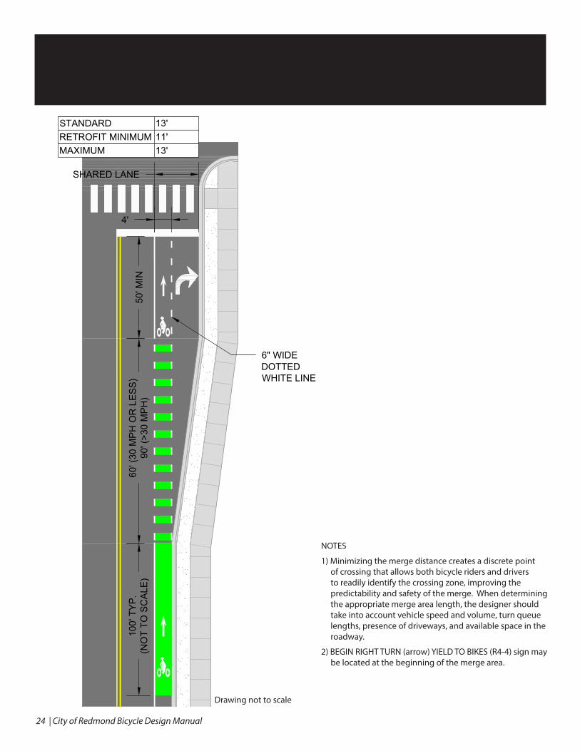
Through Bike Lane (on curb line)INTENT: High comfort facility that provides exclusive space and signal phase for bicyclists
THROUGH BIKE LANE
3'1'N/A
5'5'6'-6"
BUFFER BIKE LANE
STANDARDRETROFIT MINIMUMMAXIMUM
QU
EU
E S
TOR
AG
E L
EN
GTH
DE
PE
ND
S O
N V
OLU
ME
AN
D O
PE
RA
TIO
NS
60' (
30 M
PH
OR
LE
SS
)90
' (>3
0 M
PH
)BUF. B.L.
NOTES
1) This design requires a dedicated bicycle signal phase, exclusive from the right-turn movement.
Not drawn to scale

30 | City of Redmond Bicycle Design Manual
Left Turn Bike LaneINTENT: Low comfort facility that positions bicyclists for left turn at signalized or unsignalized location where bicycle left-turn volumes are high
LEFT TURN BIKE LANE
50' M
IN
BIKE LANE
60' (
30 M
PH
OR
LE
SS
)90
' (>3
0 M
PH
)
TRAVEL LANE
GREEN PAINTOPTIONAL
5'4'6'-6"
STANDARDRETROFIT MINIMUMMAXIMUM
BIKELANE
5'4'6'-6"
BIKELANE
NOTES
1) This treatment should only be used if there is a bicycle facility on the receiving roadway.
2) Design for bicycle through movement may vary (e.g., through lane as shown, mixing zone, etc.)
3) Minimizing the merge distance creates a discrete point of crossing that allows both bicycle riders and drivers to readily identify the crossing zone, improving the predictability and safety of the merge. When determining the appropriate merge area length, the designer should take into account vehicle speed and volume, turn queue lengths, presence of driveways, and available space in the roadway.
4) Solid green pavement markings or green background to the bike lane symbol may be used in portion of bike lane where vehicle merging is not desired and bicyclists are expected to queue.
5) Dashed lines (“chicken tracks”) may be provided through intersection to provide positioning guidance for dual left-turn movement.
6) Shared lane markings should be installed to indicate the shared lane and guide bicyclists towards the left-turn bike lane. Maximum spacing between markings is 30 feet.
Drawing not to scale
City of Redmond Bicycle Design Manual | 31
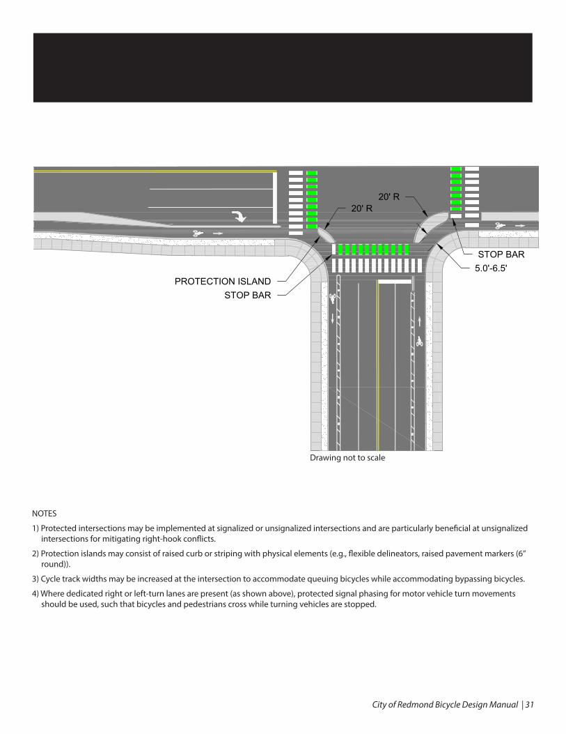
Protected IntersectionINTENT: High comfort facility that provides physical separation for bicyclists and improves sight lines of right-turning motorists.
STOP BAR
STOP BAR
20' R20' R
PROTECTED INTERSECTION
5.0'-6.5'PROTECTION ISLAND
NOTES
1) Protected intersections may be implemented at signalized or unsignalized intersections and are particularly beneficial at unsignalized intersections for mitigating right-hook conflicts.
2) Protection islands may consist of raised curb or striping with physical elements (e.g., flexible delineators, raised pavement markers (6” round)).
3) Cycle track widths may be increased at the intersection to accommodate queuing bicycles while accommodating bypassing bicycles.
4) Where dedicated right or left-turn lanes are present (as shown above), protected signal phasing for motor vehicle turn movements should be used, such that bicycles and pedestrians cross while turning vehicles are stopped.
Drawing not to scale

32 | City of Redmond Bicycle Design Manual
Two-Stage Turn Queue (no parking lane)INTENT: Provides a higher comfort way to execute a left turn.
TWO STAGE TURN QUEUE
STANDARD = 10'
(RETROFIT MIN = 8')
STANDARD = 6'-6"(RETROFIT MIN = 4')
NOTES
1) Right turn on red restriction is typically used on leg on which turn box is installed to minimize vehicle encroachment and reduce potential for conflict between bicyclists and right-turning vehicles.
2) The turn box may be placed on the left side of bicycle intersection crossing markings depending on intersection geometrics. This is the preferred installation when there is a parking-protected cycle track on the approach leg.
Drawing not to scale
City of Redmond Bicycle Design Manual | 33
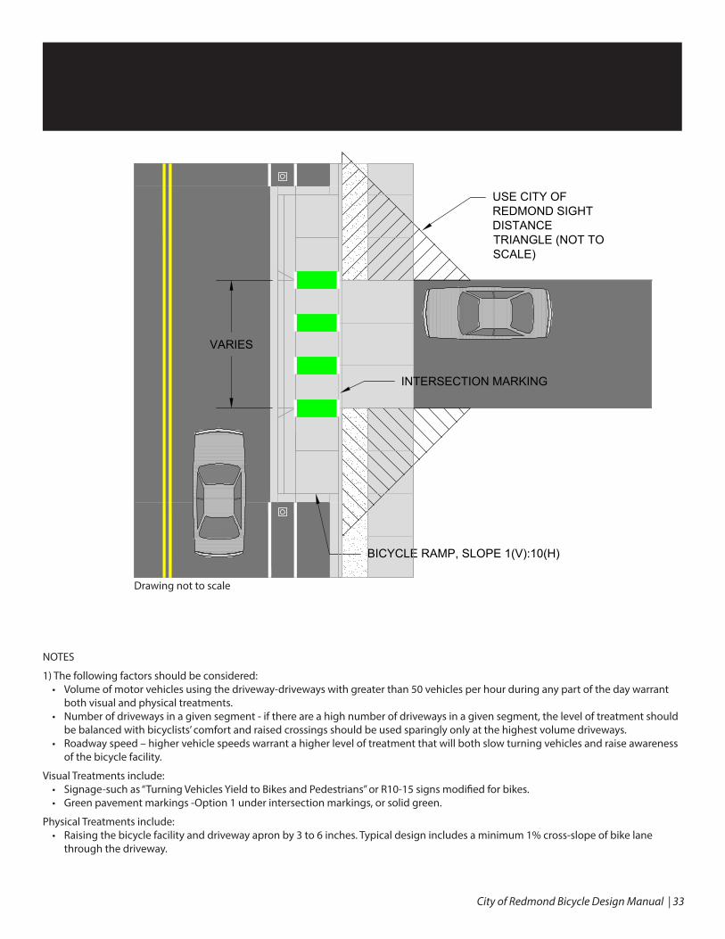
Raised Driveway Crossing
INTERSECTION MARKING
BICYCLE RAMP, SLOPE 1(V):10(H)
VARIES
USE CITY OFREDMOND SIGHTDISTANCETRIANGLE (NOT TOSCALE)
Enhanced Driveway Crossing INTENT: Improve safety and comfort of sidepath or cycle track facility by conveying bicyclists priority and requiring motorists to slow as they turn across the bikeway.
NOTES
1) The following factors should be considered:• Volume of motor vehicles using the driveway-driveways with greater than 50 vehicles per hour during any part of the day warrant
both visual and physical treatments.• Number of driveways in a given segment - if there are a high number of driveways in a given segment, the level of treatment should
be balanced with bicyclists’ comfort and raised crossings should be used sparingly only at the highest volume driveways.• Roadway speed – higher vehicle speeds warrant a higher level of treatment that will both slow turning vehicles and raise awareness
of the bicycle facility.
Visual Treatments include:• Signage-such as “Turning Vehicles Yield to Bikes and Pedestrians” or R10-15 signs modified for bikes.• Green pavement markings -Option 1 under intersection markings, or solid green.
Physical Treatments include:• Raising the bicycle facility and driveway apron by 3 to 6 inches. Typical design includes a minimum 1% cross-slope of bike lane
through the driveway.
Drawing not to scale

City of Redmond Bicycle Design Manual34
Transition Ramp
1:10 SLOPE MAX
MATCH BIKEFACILITY
STANDARD = 10'(RETROFIT MIN = 8')
10' MIN
SMOOTH TRANSITION
LOCATE 50' BEFORERAMP (NOT TO SCALE)
DETECTABLE WARNING
Transition RampINTENT: To transition bicyclists from one facility to another and/or provide bicycle access.
NOTES
1) Ramps that direct bicyclists from the roadway to a shared sidewalk or other off-street facility should be used as transition components only, including at:• Roundabouts• Bridges• Constrained locations to facilitate bicycle left turns• Locations where a bike facility transitions to a shared-use pathway, trail, or other off-street path network.• Locations where a bicyclist will be expected to dismount when entering the shared-use sidewalk such as bus stops, light rail
stations, train stations, adjacent to a school etc. Adequate space for dismounting should be provided.
2) Provide minimum 10 feet transition zone for bicyclists exiting roadway to mix with pedestrians.
3) Provide shared lane markings/transition into a shared lane for bicyclists who choose to ride in lane. This only applies to roadways with a speed limit of 35 mph and under.
Drawing not to scale

Signal Treatments

36 | City of Redmond Bicycle Design Manual
Bicycle Signal (with lead interval)INTENT: Eliminate conflicts between turning motorists and through bicyclists.
Locations
Bicycle signals are used to minimize conflict and frustration, and to increase safety and predictability for all users. A bicycle signal should be considered in the following situations:
• Peak hour left or right turn volumes exceed 100 vehicles per hour crossing a two-way or contra-flow facility.
• Peak hour left or right turn volumes exceed 150 vehicles per hour crossing a one-way facility.
• Where left-turning bicyclists are making difficult movements due to factors such as multiple lane changes with high speed differential. In this case an exclusive bike phase should be used, and the bike phase must not overlap the general vehicular green phase.
Design Requirements
Time separated movements typically require vehicle turn lanes and protected only turn phasing for vehicles crossing the bike facility. An exclusive bike phase may accomplish the same goal.
For layout of bicycle signals refer to the MUTCD in addition to the following supplemental guidance:
• Consider optically programmed or shielded bicycle signal displays if MUTCD requirements for lateral position cannot be met or if signal face visibility cannot be optimized, i.e. provide clear unmistakable indication of right-of-way.
• A supplemental 4 inch nearside display should be used if the intersection is more than 120 feet wide. A nearside signal display should be mounted such that the bottom of the signal housing is no less than 4 feet above the ground and no more than 8 feet about the ground or sidewalk.
• 8 inch bike signal heads should be mounted such that the bottom of the signal housing is no less than 7 feet above the ground or sidewalk. In locations where far-side bike signals share a pedestal with a pedestrian signal, the bike signal should be located above the pedestrian signal.

City of Redmond Bicycle Design Manual | 37
Bicycle DetectionINTENT: Automatic signal actuation for bicycles at intersections
BICYCLE DETECTION
LOCATE BICYCLEDETECTORPAVEMENT MARKINGWHERE BICYCLESWAIT (MUTCD 9C.05)
NOTES
Location
If the bicycle phase is not set to recall each cycle, bicycle detection shall be installed.
Signal detection may be necessary or provide operational improvements for:• Bicycle minimum green –provide bicycle detection at signals to allow an increased minimum green time for bicyclists where vehicle
minimum green times are too short.• Protected bicycle phases –bicycle detection will allow the signal to dynamically skip phases when bicyclists are not present.
Consider with exclusive bicycle phases or where time separated turn restrictions exist. • Advanced detection – Advanced detection can be used to call a green for an approaching cyclist or extend the green phase up to
the maximum as appropriate• Turn on Red Restrictions – bicycle detection may also be used to activate variable turn on red restriction signs• Bicycle detection should also be considered for 24/7 counting purposes
Design Requirements• Detection symbols at signals shall be placed where bicyclists wait. Prefer either in the center of a bike box or immediately behind the
stop bar in the bike lane. Intersections without painted bicycle infrastructure should provide detection in the center of the outside lane.
• Passive actuation of bicycle signals through loops or another detection method is preferred to the use of push buttons for actuation. • Refer to MUTCD 9C-7 or CoR SD 320A for detail. Type D or diagonal quadruple loop detectors allow for bicycles to be detected
across the entire width of the loop while rejecting vehicles in adjacent lanes. Thermal camera technology should be considered on approaches with three or more lanes given its effectiveness, flexibility in terms of optimizing detection, and comparable costs to loop detectors in this context.
• If push buttons are used, they should be mounted curbside such that bicyclists do not have to dismount to actuate the signal or accessed via a curb ramp designed to accommodate bicycle movements to the button.

38 | City of Redmond Bicycle Design Manual
Right Turn on Red (RTOR) RestrictionINTENT: Reduce conflicts between turning vehicles and bicyclists.
Locations
RTOR restrictions are typically used in the following situations:
• Two-stage turn queue box – At locations where a two-stage turn queue box is provided to facilitate bicyclist left-turns, restrict turns from the street on which the turn queue box is placed because turning drivers are likely to obstruct the queue box.
• Locations with bike boxes – At locations where a bike box is provided to create an advanced stop and queue area for cyclists. The No Turn on Red restriction is needed to enforce motor vehicles stopping and staying in the correct location prior to the bike box.
• Two-way cycle track – At locations where a two-way cycle track is present, restrict right turns from the street intersecting with the facility, as drivers may not anticipate conflicts from cyclists approaching from the contra-flow direction.
• Exclusive bike phase – At locations where traffic signal phasing includes an exclusive bike phase restrict turns on red for all movements which would conflict with the exclusive phase.
RTOR restrictions should be considered in the following conditions:
• Encroachment – at intersections where a bike lane is present and vehicles are observed encroaching into the bike lane to pass queued vehicles on the right when making right turn on red movements.
• Limited sight distance – at intersections where sight distance may be insufficient for vehicles approaching from the left (or right, if applicable). A sight distance of less than 190 feet for a 30 mph speed may be considered for a RTOR restriction (AASHTO Stopping Sight Distance).
• Unique geometric configurations – at intersections where streets do not cross at 90 degrees; or where more than two streets intersect (i.e. 5-leg intersection), which may result in unexpected movements.
• Crashes – at locations where right-turns-on-red have resulted in a bicycle or pedestrian crash.
Design Considerations
• NO TURN ON RED signage often is installed near the appropriate signal head on approaches that meet the above criteria.
• Alternative treatments such as modifying the placement of stop bars to improve sight distances to approaching bicyclists should be evaluated.
City of Redmond Bicycle Design Manual | 39
Additional Design Treatments
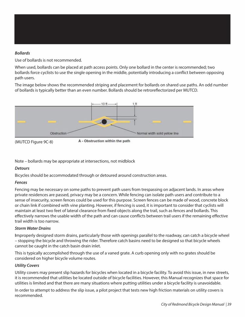
Bollards
Use of bollards is not recommended.
When used, bollards can be placed at path access points. Only one bollard in the center is recommended; two bollards force cyclists to use the single opening in the middle, potentially introducing a conflict between opposing path users.
The image below shows the recommended striping and placement for bollards on shared use paths. An odd number of bollards is typically better than an even number. Bollards should be retroreflectorized per MUTCD.
Note – bollards may be appropriate at intersections, not midblock
Detours
Bicycles should be accommodated through or detoured around construction areas.
Fences
Fencing may be necessary on some paths to prevent path users from trespassing on adjacent lands. In areas where private residences are passed, privacy may be a concern. While fencing can isolate path users and contribute to a sense of insecurity, screen fences could be used for this purpose. Screen fences can be made of wood, concrete block or chain link if combined with vine planting. However, if fencing is used, it is important to consider that cyclists will maintain at least two feet of lateral clearance from fixed objects along the trail, such as fences and bollards. This effectively narrows the usable width of the path and can cause conflicts between trail users if the remaining effective trail width is too narrow.
Storm Water Drains
Improperly designed storm drains, particularly those with openings parallel to the roadway, can catch a bicycle wheel – stopping the bicycle and throwing the rider. Therefore catch basins need to be designed so that bicycle wheels cannot be caught in the catch basin drain inlet.
This is typically accomplished through the use of a vaned grate. A curb opening only with no grates should be considered on higher bicycle volume routes.
Utility Covers
Utility covers may present slip hazards for bicycles when located in a bicycle facility. To avoid this issue, in new streets, it is recommended that utilities be located outside of bicycle facilities. However, this Manual recognizes that space for utilities is limited and that there are many situations where putting utilities under a bicycle facility is unavoidable.
In order to attempt to address the slip issue, a pilot project that tests new high friction materials on utility covers is recommended.
(MUTCD Figure 9C-8)
40 | City of Redmond Bicycle Design Manual
Long-term Bicycle Parking Guidelines
City of Redmond
Long-Term Bicycle Parking Guidelines
2016

City of Redmond Bicycle Design Manual | 41
SvR # 11026
City of Redmond Long-Term Bicycle Parking Guidelines
PURPOSE
This section provides detail regarding bicycle parking guidelines in the Redmond Bicycle Facilities DesignManual for locating and designing secure, long-term bicycle parking facilities in accordance with theCity of Redmond's bicycle parking requirements as published in Section 21.40.020 of the RedmondZoning Code. Additional information regarding bicycle parking and other bicycle related design issuesare addressed in the Redmond Bicycle Facilities Design Manual and the American Pedestrian and Bicycle Professionals Essentials of Bike Parking, 2015.
DESIGN CONSIDERATION
Security: Long-term bicycle parking needs to be located in a secure location where access to the bicycles is limited and is not available to the general public. Secure access can be achieved in any of the following ways:
• Designated indoor bike room with locking system • Bike cage with locking system in a parking garage • Uncaged bike parking in a garage or area with 24-hour secured access (protect bike parking areas
not in a cage from autos with bollards, curbs, or other means) • Individual bicycle lockers with locking system • Designated bike space with racks inside an office area which can be locked when it is not occupied • If garage racks are accessible to the general public they must be directly adjacent to an attendant
booth that is occupied 24-hours a day
PUBLIC AWARENESS AND ACCEPTANCE
Notifying building occupants of the availability of easily accessible and convenient to use long-term bike parking will ensure that it is well used and an important amenity for all.
• Locate bicycle parking in a well-lit, well-traveled area • Follow guidelines for proper layout and installation of the bike racks • Inform building users of this important amenity • Identify bicycle parking with prominent signage • Consider including other amenities, such as a bicycle tool station or lockers for cyclists' personal
effects and bike gear
BICYCLE RACK TYPES
Rack types are to be approved by the Transportation Planning & Engineering Manager. For a list of rack types see Essentials of Bike Parking, 2015 published by the Association of Pedestrian and Bicycle Professionals (APBP). Acceptable rack types include:
• Inverted U (single or fastened in series) • Post and Ring

42 | City of Redmond Bicycle Design Manual
SvR # 11026
• Wall-Mounted Racks with fixed attachment points • Wheel well - Secured, with arm or feature that supports frame • Modified Coat hanger • Two-Tier, or Double-Decker (lift assist preferred)
Whichever type of rack is selected, the rack should provide users with the ability to securely lock their bicycle to the rack. Because rack dimensions, bicycle spacing, and additional features such as locking or support mechanisms vary by manufacturer, check to ensure that selected racks comply with the minimum dimensions recommended in these guidelines.
LAYOUT, ACCESS AND CLEARANCE
The layout, access and clearance of long-term bicycle parking are critical to it being a useful amenity for a development.
• See the figures on the following pages for guidance and examples of rack layout within secure, long-term bicycle parking facilities, including general rack and aisle spacing dimensions
• A minimum 3 feet parallel spacing between conventional ground-level bicycle racks (e.g. inverted-U racks) to allow access to bicycles parked adjacent to each other
• A minimum 5 feet perpendicular access aisle between rows of bicycle parking to allow users to safely move and park their bicycles
• A minimum 2 feet 6 inches perpendicular spacing between a row of conventional ground-level bicycle racks (e.g. inverted-U racks) and walls or obstructions to allow the bike to be placed correctly on the rack
• Allow 24" minimum clearance for user access between a wall or other obstruction and the side of the nearest parked bicycle (may use 18" minimum for some rack types such as wall-mount)
• Provide at least 25% ground-level bicycle parking spaces, to allow for use by those unable to lift their bicycles to higher racks and those with bicycle types that may not fit in upper-level or wall-hanging racks (e.g. recumbents, folding bicycles, cargo bicycles, or those with trailers)
SPECIAL CONSIDERATIONS
• Providing bicycle parking at the end of a parking stall intended for use also by a motorized vehicle is not acceptable
• A single-family townhome with secure garage is exempt from the bicycle parking requirement, as the garage may be used for secure bicycle parking

City of Redmond Bicycle Design Manual | 43

44 | City of Redmond Bicycle Design Manual