Embed Size (px)
Citation preview
Table of Contents
1 Introduction ........................................................................................................ 41.1 About this manual ......................................................................................................................................... 51.2 Important user information ....................................................................................................................... 61.3 Associated documentation ....................................................................................................................... 8
2 Safety instructions ............................................................................................. 92.1 Safety precautions ........................................................................................................................................ 102.2 Labels ................................................................................................................................................................. 162.3 Emergency procedures ............................................................................................................................... 17
3 System description ............................................................................................ 193.1 Biacore S200 instrument components ................................................................................................. 203.2 Indicators and switches ............................................................................................................................... 273.3 Sample and reagent racks .......................................................................................................................... 293.4 Sensor chip and flow system ..................................................................................................................... 313.5 Temperature control .................................................................................................................................... 333.6 Control system ............................................................................................................................................... 34
4 Installation .......................................................................................................... 354.1 Site requirements .......................................................................................................................................... 364.2 Unpacking, assembly and transport ....................................................................................................... 394.3 Connections ..................................................................................................................................................... 40
5 Operation ............................................................................................................ 425.1 Starting the system ....................................................................................................................................... 445.2 Preparing the instrument ........................................................................................................................... 455.3 Ejecting the rack tray .................................................................................................................................... 495.4 Adjusting the rack tray ................................................................................................................................. 515.5 Preparing samples and reagents ............................................................................................................. 525.6 Changing reagent racks .............................................................................................................................. 545.7 Installing the rack tray ................................................................................................................................. 555.8 Starting and finishing a run ........................................................................................................................ 56
6 Maintenance ....................................................................................................... 576.1 Maintenance preparations ........................................................................................................................ 596.2 Maintenance summary ............................................................................................................................... 606.3 User maintenance operations .................................................................................................................. 626.4 User service operations ............................................................................................................................... 666.5 Shutting down the system .......................................................................................................................... 726.6 Replacing the mains fuses .......................................................................................................................... 74
7 Troubleshooting ................................................................................................. 767.1 System-related problems ........................................................................................................................... 777.2 Assay-related problems .............................................................................................................................. 79
Table of Contents
2 Biacore S200 Operating Instructions 29143106 AD
8 Reference information ....................................................................................... 808.1 Specifications .................................................................................................................................................. 818.2 Maintenance tools ......................................................................................................................................... 848.3 Chemical resistance ..................................................................................................................................... 898.4 Recycling information .................................................................................................................................. 908.5 Regulatory information ............................................................................................................................... 91
8.5.1 Contact information .................................................................................................................................... 928.5.2 European Union and European Economic Area .............................................................................. 938.5.3 Eurasian Economic Union
Евразийский экономический союз .................................................................................................. 948.5.4 Regulations for North America ............................................................................................................... 968.5.5 Regulatory statements .............................................................................................................................. 978.5.6 Declaration of Hazardous Substances (DoHS) ................................................................................ 988.5.7 Other regulations and standards .......................................................................................................... 100
8.6 Health and Safety Declaration Form ...................................................................................................... 101
A Appendix A: Software tool texts ........................................................................ 103A.1 Maintenance tools ......................................................................................................................................... 104A.2 Test tools ........................................................................................................................................................... 109A.3 Service tools ..................................................................................................................................................... 110
B Appendix B: Technical description ................................................................... 112B.1 Detection principle ........................................................................................................................................ 113B.2 Buffer and sample handling ....................................................................................................................... 115
Index ........................................................................................................................... 118
Table of Contents
Biacore S200 Operating Instructions 29143106 AD 3
1 Introduction
About this chapterThis chapter contains important user information, descriptions of safety notices,intended use of the Biacore™ S200 system, and lists of associated documentation.
In this chapter
Section See page
1.1 About this manual 5
1.2 Important user information 6
1.3 Associated documentation 8
1 Introduction
4 Biacore S200 Operating Instructions 29143106 AD
1.1 About this manual
Purpose of this manualThe Operating Instructions provide you with the information needed to install, operateand maintain the product in a safe way.
Typographical conventionsSoftware items are identified in the text by bold italic text.
Hardware items are identified in the text by bold text.
In electronic format, references in italics are clickable hyperlinks.
1 Introduction1.1 About this manual
Biacore S200 Operating Instructions 29143106 AD 5
1.2 Important user information
Read this before operating theproduct
All users must read the entire Operating Instructions before installing, oper-ating or maintaining the product.
Always keep the Operating Instructions at hand when operating the product.
Do not operate the product in any other way than described in the user documenta-tion. If you do, you may be exposed to hazards that can lead to personal injury and youmay cause damage to the equipment.
Intended use of the productBiacore S200 is a system for real-time label-free analysis of molecular interactions inlaboratory research. Biacore S200 is intended for research use only and shall not beused for diagnostic purposes in any clinical or in vitro procedures.
PrerequisitesIn order to operate Biacore S200 in the way it is intended:
• The user must read and understand the Safety instructions chapter in the OperatingInstructions.
• The system must be installed according to the instructions in the Installationchapter of the Operating Instructions.
• The user must have a general understanding of the use of a personal computerrunning Microsoft ® Windows ® in the version provided with your product.
• The user must be acquainted with the use of general laboratory equipment and withhandling of biological materials.
Safety noticesThis user documentation contains safety notices (WARNING, CAUTION, and NOTICE)concerning the safe use of the product. See definitions below.
WARNING
WARNING indicates a hazardous situation which, if not avoided,could result in death or serious injury. It is important not to proceeduntil all stated conditions are met and clearly understood.
1 Introduction1.2 Important user information
6 Biacore S200 Operating Instructions 29143106 AD

CAUTION
CAUTION indicates a hazardous situation which, if not avoided,could result in minor or moderate injury. It is important not toproceed until all stated conditions are met and clearly understood.
NOTICE
NOTICE indicates instructions that must be followed to avoiddamage to the product or other equipment.
Notes and tipsNote: A note is used to indicate information that is important for trouble-free and
optimal use of the product.
Tip: A tip contains useful information that can improve or optimize your proce-dures.
1 Introduction1.2 Important user information
Biacore S200 Operating Instructions 29143106 AD 7
1.3 Associated documentation
IntroductionThis section describes the user documentation that is delivered with the product, andhow to find related literature that can be downloaded or ordered from Cytiva.
User documentationOperation of the Control and Evaluation Software is described in the Biacore S200 Soft-ware Handbook.
Sensor surface preparation and general methodology for Biacore applications aredescribed in the Biacore Sensor Surface Handbook and the Biacore Assay Handbookrespectively. Methodology for concentration measurement using Biacore systems isdescribed in the Biacore Concentration Analysis Handbook.
Data files, application notes and userdocumentation on the web
To order or download data files, application notes or user documentation, see theinstruction below.
Step Action
1 Go to cytiva.com/biacore.
2 Click Biacore S200.
3 Click RELATED DOCUMENTS.
4 Select to download the chosen literature.
1 Introduction1.3 Associated documentation
8 Biacore S200 Operating Instructions 29143106 AD
2 Safety instructions
About this chapterThis chapter describes safety precautions, labels and symbols that are attached to theequipment. In addition, the chapter describes emergency and recovery procedures.
Important
WARNINGBefore installing, operating or maintaining the product, allusers must read and understand the entire contents of thischapter to become aware of the hazards involved.
In this chapter
Section See page
2.1 Safety precautions 10
2.2 Labels 16
2.3 Emergency procedures 17
2 Safety instructions
Biacore S200 Operating Instructions 29143106 AD 9
2.1 Safety precautions
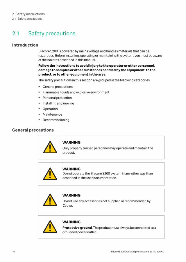
IntroductionBiacore S200 is powered by mains voltage and handles materials that can behazardous. Before installing, operating or maintaining the system, you must be awareof the hazards described in this manual.
Follow the instructions to avoid injury to the operator or other personnel,damage to samples or other substances handled by the equipment, to theproduct, or to other equipment in the area.
The safety precautions in this section are grouped in the following categories:
• General precautions
• Flammable liquids and explosive environment
• Personal protection
• Installing and moving
• Operation
• Maintenance
• Decommissioning
General precautions
WARNING
Only properly trained personnel may operate and maintain theproduct.
WARNINGDo not operate the Biacore S200 system in any other way thandescribed in the user documentation.
WARNING
Do not use any accessories not supplied or recommended byCytiva.
WARNING
Protective ground. The product must always be connected to agrounded power outlet.
2 Safety instructions2.1 Safety precautions
10 Biacore S200 Operating Instructions 29143106 AD
WARNING
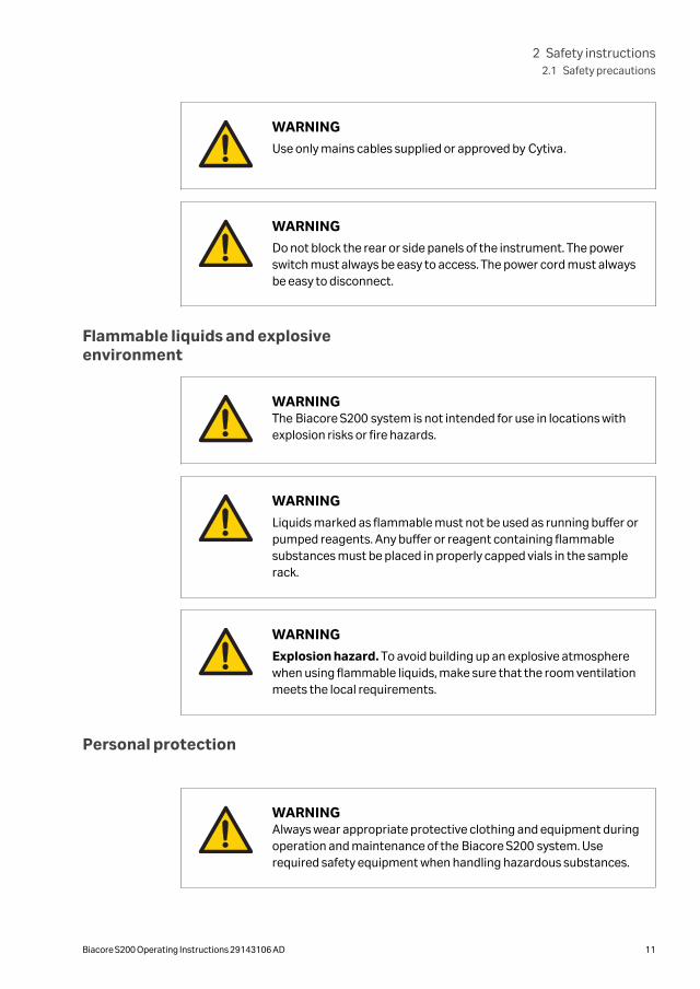
Use only mains cables supplied or approved by Cytiva.
WARNING
Do not block the rear or side panels of the instrument. The powerswitch must always be easy to access. The power cord must alwaysbe easy to disconnect.
Flammable liquids and explosiveenvironment
WARNINGThe Biacore S200 system is not intended for use in locations withexplosion risks or fire hazards.
WARNING
Liquids marked as flammable must not be used as running buffer orpumped reagents. Any buffer or reagent containing flammablesubstances must be placed in properly capped vials in the samplerack.
WARNING
Explosion hazard. To avoid building up an explosive atmospherewhen using flammable liquids, make sure that the room ventilationmeets the local requirements.
Personal protection
WARNINGAlways wear appropriate protective clothing and equipment duringoperation and maintenance of the Biacore S200 system. Userequired safety equipment when handling hazardous substances.
2 Safety instructions2.1 Safety precautions
Biacore S200 Operating Instructions 29143106 AD 11
WARNING
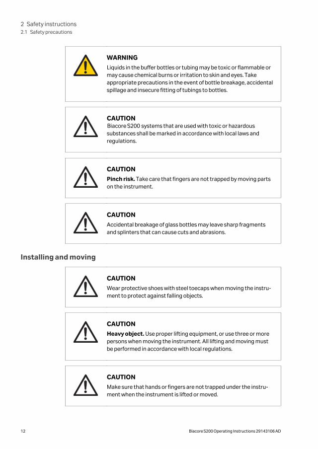
Liquids in the buffer bottles or tubing may be toxic or flammable ormay cause chemical burns or irritation to skin and eyes. Takeappropriate precautions in the event of bottle breakage, accidentalspillage and insecure fitting of tubings to bottles.
CAUTIONBiacore S200 systems that are used with toxic or hazardoussubstances shall be marked in accordance with local laws andregulations.
CAUTION
Pinch risk. Take care that fingers are not trapped by moving partson the instrument.
CAUTION
Accidental breakage of glass bottles may leave sharp fragmentsand splinters that can cause cuts and abrasions.
Installing and moving
CAUTION
Wear protective shoes with steel toecaps when moving the instru-ment to protect against falling objects.
CAUTION
Heavy object. Use proper lifting equipment, or use three or morepersons when moving the instrument. All lifting and moving mustbe performed in accordance with local regulations.
CAUTION
Make sure that hands or fingers are not trapped under the instru-ment when the instrument is lifted or moved.
2 Safety instructions2.1 Safety precautions
12 Biacore S200 Operating Instructions 29143106 AD
Operation
WARNING
Handle bottles carefully. Accidental breakage of buffer or waterbottles may cause flooding of the bottle tray, and liquid may comeinto contact with electrical circuits, causing electric shock and/orfire hazards.
WARNING
A fume hood or similar ventilation system shall be installed whenflammable or noxious substances are used.
WARNING
Waste liquids may contain hazardous or flammable substances.Take appropriate precautions to avoid spillage of hazardous waste.
CAUTION
Accidental breakage of buffer or water bottles may cause floodingof the bottle tray, and liquid may enter the instrument enclosure. Ifthis happens, disconnect the instrument from the mains power andcall your local service representative.
CAUTION
Do not touch the pumps while they are moving.
CAUTION
Ensure that all fluidic tubes are secured and properly connected orsealed at both ends before, during and after operation.
CAUTION
Waste tubes and containers must be secured and sealed toprevent accidental spillage.
2 Safety instructions2.1 Safety precautions
Biacore S200 Operating Instructions 29143106 AD 13
CAUTION
Make sure that the waste container has sufficient space formaximum waste volume when the equipment is left unattended.
Maintenance
WARNING
All service and repairs, with the exception of operations explicitlydescribed in the user documentation, must be carried out bypersonnel authorized by Cytiva. Do not open any covers or replaceany parts unless specifically stated in the user documentation.
WARNINGThe Biacore S200 system contains mains voltage of up to 240 V AC.Disconnect mains cord before replacing fuses. Do not removeinstrument covers.
WARNING
For continued protection from fire hazard, replace only with sametype and rating of fuse.
WARNING
If the instrument may be contaminated with biohazards, decon-taminate the instrument before performing maintenance on anyinstrument parts. Contact your local service representative forfurther information about decontamination procedures.
CAUTION
Always turn off the power before opening the sample compart-ment.
2 Safety instructions2.1 Safety precautions
14 Biacore S200 Operating Instructions 29143106 AD
CAUTION
The sample compartment door swings upwards when released. Donot lean over the instrument when you open the sample compart-ment door.
Decommissioning
WARNING
Decontaminate the equipment before decommissioning to ensurethat hazardous residues are removed.
2 Safety instructions2.1 Safety precautions
Biacore S200 Operating Instructions 29143106 AD 15
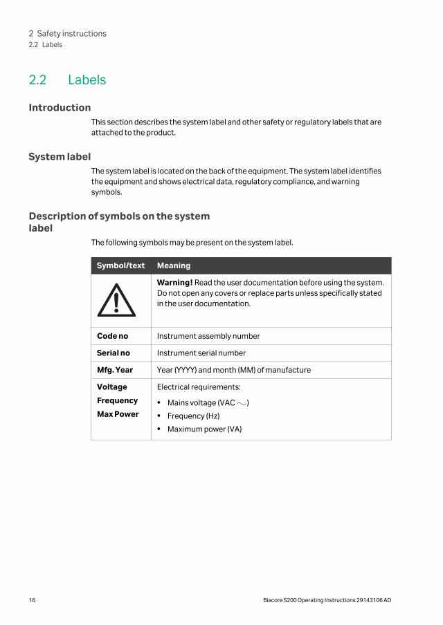
2.2 Labels
IntroductionThis section describes the system label and other safety or regulatory labels that areattached to the product.
System labelThe system label is located on the back of the equipment. The system label identifiesthe equipment and shows electrical data, regulatory compliance, and warningsymbols.
Description of symbols on the systemlabel
The following symbols may be present on the system label.
Symbol/text Meaning
Warning! Read the user documentation before using the system.Do not open any covers or replace parts unless specifically statedin the user documentation.
Code no Instrument assembly number
Serial no Instrument serial number
Mfg. Year Year (YYYY) and month (MM) of manufacture
Voltage
Frequency
Max Power
Electrical requirements:
• Mains voltage (VAC )
• Frequency (Hz)
• Maximum power (VA)
2 Safety instructions2.2 Labels
16 Biacore S200 Operating Instructions 29143106 AD
2.3 Emergency procedures
IntroductionThis section describes how to shut down the Biacore S200 system in an emergencysituation, and the procedure for restarting the Biacore S200 system.
The section also describes the result in the event of power failure.
NOTICE
Do not use the acute emergency stop procedure unless there is arisk of injury, damage or loss of valuable material. All operationsincluding buffer flow and data collection are stopped immediately.
To stop a run under controlled conditions before it is complete, choose Run →StopRun Sensorgram from the menu bar in Biacore S200 Control Software. This will stopboth the run and the data collection at the end of the current cycle. A dialog isdisplayed while the current cycle is finished.
Emergency shutdown
In an emergency situation, follow the steps below to stop the run.
Step Action
1 Press Ctrl-Break (Ctrl-Pause) on the keyboard to stop the run and the datacollection immediately.
2 In the dialog box that appears, click Yes if you want to wash the system withrunning buffer. You should do this if possible. The wash operation takesabout 3 minutes.
NOTICE
Do not leave the system in an emergency stop condition. Alwaysfollow the restart procedure if possible, to restore the instrumentto normal condition.
Power failureThe following table describes the consequences of a power failure.
2 Safety instructions2.3 Emergency procedures
Biacore S200 Operating Instructions 29143106 AD 17
Power failureto...
will result in...
Biacore S200instrument
• The run is interrupted immediately.
• Data collected up to and including the last cyclecompleted before the power failure is saved in the resultfile.
Computer • The computer shuts down immediately.
• Instrument operation continues for a short time (until theinternal data buffer is full) and then stops.
• Data collected up to and including the last cyclecompleted before the power failure is saved in the resultfile, but there is a risk that the result file may be corrupt andcannot be read.
Restart procedure
Follow the steps below to restart the system after an emergency shutdown.
Step Action
1 Turn on mains power if it is switched off and check that the instrument startsnormally.
2 If you need to clean the liquid handling system, eject the sensor chip andinsert a maintenance chip. See Cleaning and disinfecting the flow system, onpage 63 for further instructions.
2 Safety instructions2.3 Emergency procedures
18 Biacore S200 Operating Instructions 29143106 AD
3 System description
About this chapterThis chapter gives an overview of the Biacore S200 system, and a brief description of itsfunction.
In this chapter
Section See page
3.1 Biacore S200 instrument components 20
3.2 Indicators and switches 27
3.3 Sample and reagent racks 29
3.4 Sensor chip and flow system 31
3.5 Temperature control 33
3.6 Control system 34
3 System description
Biacore S200 Operating Instructions 29143106 AD 19
3.1 Biacore S200 instrument components
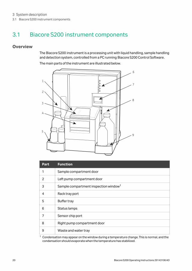
OverviewThe Biacore S200 instrument is a processing unit with liquid handling, sample handlingand detection system, controlled from a PC running Biacore S200 Control Software.
The main parts of the instrument are illustrated below.
1
4
3
2
5
6
7
8
9
Part Function
1 Sample compartment door
2 Left pump compartment door
3 Sample compartment inspection window1
4 Rack tray port
5 Buffer tray
6 Status lamps
7 Sensor chip port
8 Right pump compartment door
9 Waste and water tray
1 Condensation may appear on the window during a temperature change. This is normal, and thecondensation should evaporate when the temperature has stabilized.
3 System description3.1 Biacore S200 instrument components
20 Biacore S200 Operating Instructions 29143106 AD
Bottle traysThe buffer tray on the left of the instrument holds up to four bottles for running buffer.Up to four different buffers can be used.
The waste and water tray on the right of the instrument holds one 2-liter bottle forwaste solutions, and one 500 mL bottle for distilled water. Bottles with caps areprovided with the system.
The bottle trays are designed to hold standard bottles threaded for screw caps. One 1-liter bottle and three 250 mL bottles with gaskets are provided with the system.
WARNING
Liquids in the buffer bottles or tubing may be toxic or flammable ormay cause chemical burns or irritation to skin and eyes. Takeappropriate precautions in the event of bottle breakage, accidentalspillage and insecure fitting of tubings to bottles.
CAUTION
Accidental breakage of buffer or water bottles may cause floodingof the bottle tray, and liquid may enter the instrument enclosure. Ifthis happens, disconnect the instrument from the mains power andcall your local service representative.
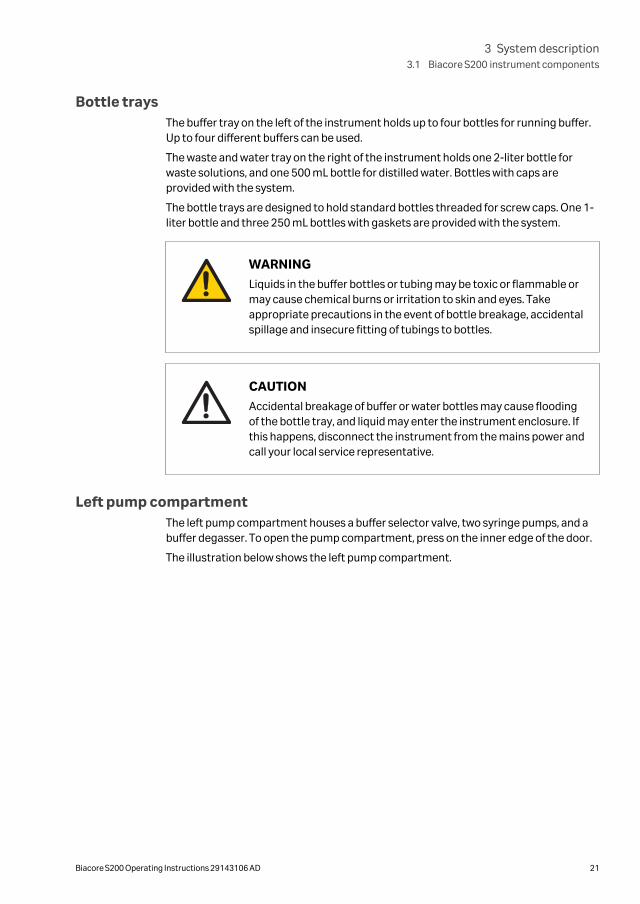
Left pump compartmentThe left pump compartment houses a buffer selector valve, two syringe pumps, and abuffer degasser. To open the pump compartment, press on the inner edge of the door.
The illustration below shows the left pump compartment.
3 System description3.1 Biacore S200 instrument components
Biacore S200 Operating Instructions 29143106 AD 21
1
2
3
4
5
Part Function
1 Holder for unused buffer tubes
2 Buffer degasser
3 Syringe pump
4 Buffer selector valve
5 Buffer tray
Buffer tubing and selector valve
The buffer tubes, marked A, B, C, and D, are connected to the inputs of a buffer selectorvalve, which determines which of the buffers is used during a run. Buffer selection iscontrolled from the software. Buffer A is selected by default.
Attach unused buffer tubes to the tubing holder inside the pump compartment door.
Buffer degasser
The gas content of the running buffer is reduced to a low level by a vacuum degasser.This eliminates the need to degas running buffer before use.
The vacuum pump of the degasser operates automatically as soon as the flow systemis started.
3 System description3.1 Biacore S200 instrument components
22 Biacore S200 Operating Instructions 29143106 AD
NOTICE
The buffer tubing should always be connected via the bufferdegasser. Do not disconnect tubes from the degasser even if youuse degassed buffer.
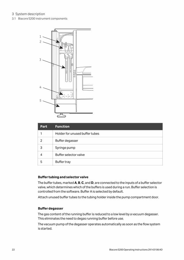
Right pump compartmentThe right pump compartment houses a peristaltic pump for supply of buffer and waterto the liquid supply block. To open the pump compartment, press on the inner edge ofthe door.
CAUTION
The peristaltic pump may operate at any time during a run orstandby. Keep your hands clear of the pump if you open the rightpump compartment door during operation.
CAUTION
Waste tubes and containers shall be secured and sealed to preventaccidental spillage.
The illustration below shows the right pump compartment.
1
2
3 System description3.1 Biacore S200 instrument components
Biacore S200 Operating Instructions 29143106 AD 23
Part Function
1 Peristaltic pump
2 Waste and water tray
The waste tubes are fitted on the waste bottle cap. Before starting a run, ensure thatthe tube fittings are tightened and that the waste bottle is empty.
WARNING
Waste liquids may contain hazardous or flammable substances.Take appropriate precautions to avoid spillage of hazardous waste.
NOTICE
The waste bottle and the cap must be of the same type and size asthe ones delivered with the system to avoid pressure disturbancesin the liquid handling system.
Sample compartmentThe temperature-controlled sample compartment holds the autosampler and thesample injection unit. The rack tray port on the front of the instrument is controlledfrom the software.
Illumination of the sample compartment can be switched on and off from the software.
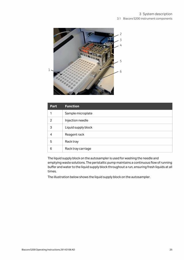
AutosamplerSamples and reagents are held in a microplate and/or rack in the autosampler and aredispensed from there through the injection needle.
The illustration below shows the autosampler.
3 System description3.1 Biacore S200 instrument components
24 Biacore S200 Operating Instructions 29143106 AD
1
2
3
5
4
6
Part Function
1 Sample microplate
2 Injection needle
3 Liquid supply block
4 Reagent rack
5 Rack tray
6 Rack tray carriage
The liquid supply block on the autosampler is used for washing the needle andemptying waste solutions. The peristaltic pump maintains a continuous flow of runningbuffer and water to the liquid supply block throughout a run, ensuring fresh liquids at alltimes.
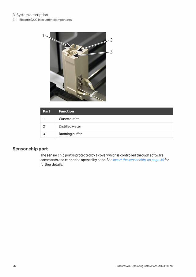
The illustration below shows the liquid supply block on the autosampler.
3 System description3.1 Biacore S200 instrument components
Biacore S200 Operating Instructions 29143106 AD 25
3
21
Part Function
1 Waste outlet
2 Distilled water
3 Running buffer
Sensor chip portThe sensor chip port is protected by a cover which is controlled through softwarecommands and cannot be opened by hand. See Insert the sensor chip, on page 45 forfurther details.
3 System description3.1 Biacore S200 instrument components
26 Biacore S200 Operating Instructions 29143106 AD
3.2 Indicators and switches
Status indicatorsThe status indicators on the front panel are described below.
Indicator Function
ready (green) Lit when power is on
system (red) Lit for a few seconds after the power is switched on. If theindicator lights in other circumstances, turn off theinstrument and call your Cytiva service representative.
temperature (yellow) Lit when the temperature at the flow cells is stable at thepreset temperature. Flashes when the temperature is notstable.
sensor chip (green) Lit when a sensor chip is docked and ready. Flashing whena chip is inserted but not docked.
run (green) Lit when a run is in progress.
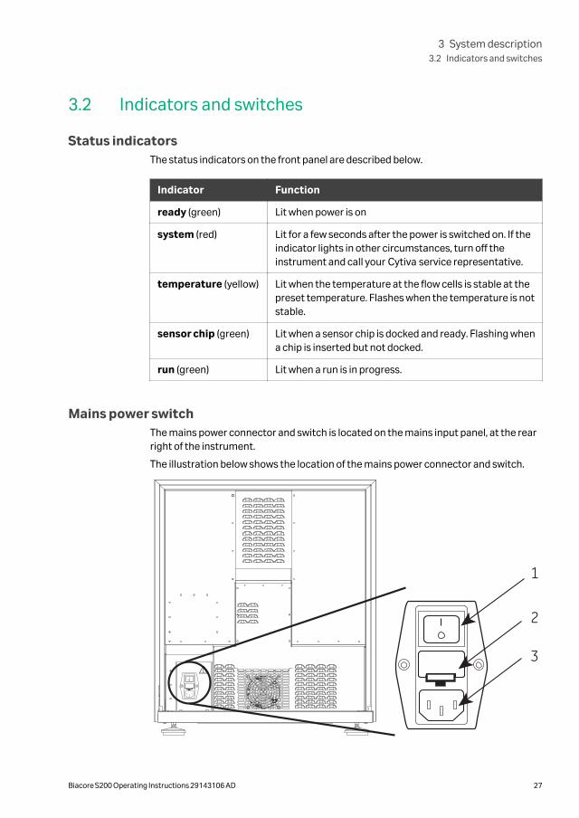
Mains power switchThe mains power connector and switch is located on the mains input panel, at the rearright of the instrument.
The illustration below shows the location of the mains power connector and switch.
1
2
3
3 System description3.2 Indicators and switches
Biacore S200 Operating Instructions 29143106 AD 27

Part Function
1 Power on/off switch
2 Fuse holder
3 Power connector
Note: For warning texts, see Section 6.6 Replacing the mains fuses, on page 74.
3 System description3.2 Indicators and switches
28 Biacore S200 Operating Instructions 29143106 AD
3.3 Sample and reagent racks
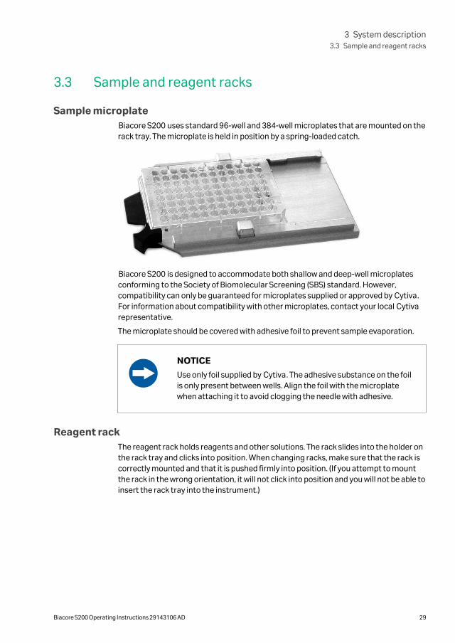
Sample microplateBiacore S200 uses standard 96-well and 384-well microplates that are mounted on therack tray. The microplate is held in position by a spring-loaded catch.
Biacore S200 is designed to accommodate both shallow and deep-well microplatesconforming to the Society of Biomolecular Screening (SBS) standard. However,compatibility can only be guaranteed for microplates supplied or approved by Cytiva.For information about compatibility with other microplates, contact your local Cytivarepresentative.
The microplate should be covered with adhesive foil to prevent sample evaporation.
NOTICE
Use only foil supplied by Cytiva. The adhesive substance on the foilis only present between wells. Align the foil with the microplatewhen attaching it to avoid clogging the needle with adhesive.
Reagent rackThe reagent rack holds reagents and other solutions. The rack slides into the holder onthe rack tray and clicks into position. When changing racks, make sure that the rack iscorrectly mounted and that it is pushed firmly into position. (If you attempt to mountthe rack in the wrong orientation, it will not click into position and you will not be able toinsert the rack tray into the instrument.)
3 System description3.3 Sample and reagent racks
Biacore S200 Operating Instructions 29143106 AD 29
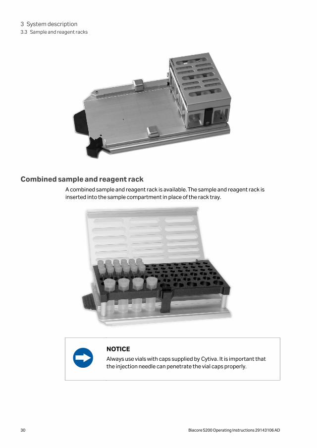
Combined sample and reagent rackA combined sample and reagent rack is available. The sample and reagent rack isinserted into the sample compartment in place of the rack tray.
NOTICE
Always use vials with caps supplied by Cytiva. It is important thatthe injection needle can penetrate the vial caps properly.
3 System description3.3 Sample and reagent racks
30 Biacore S200 Operating Instructions 29143106 AD
3.4 Sensor chip and flow system
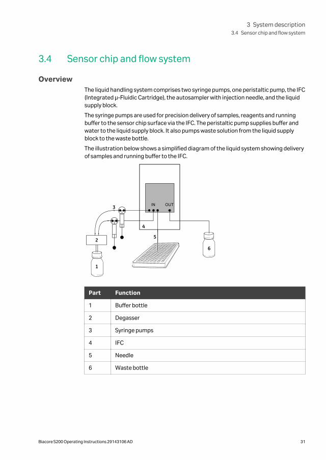
OverviewThe liquid handling system comprises two syringe pumps, one peristaltic pump, the IFC(Integrated µ-Fluidic Cartridge), the autosampler with injection needle, and the liquidsupply block.
The syringe pumps are used for precision delivery of samples, reagents and runningbuffer to the sensor chip surface via the IFC. The peristaltic pump supplies buffer andwater to the liquid supply block. It also pumps waste solution from the liquid supplyblock to the waste bottle.
The illustration below shows a simplified diagram of the liquid system showing deliveryof samples and running buffer to the IFC.
1
2
3
4
5
6
Part Function
1 Buffer bottle
2 Degasser
3 Syringe pumps
4 IFC
5 Needle
6 Waste bottle
3 System description3.4 Sensor chip and flow system
Biacore S200 Operating Instructions 29143106 AD 31
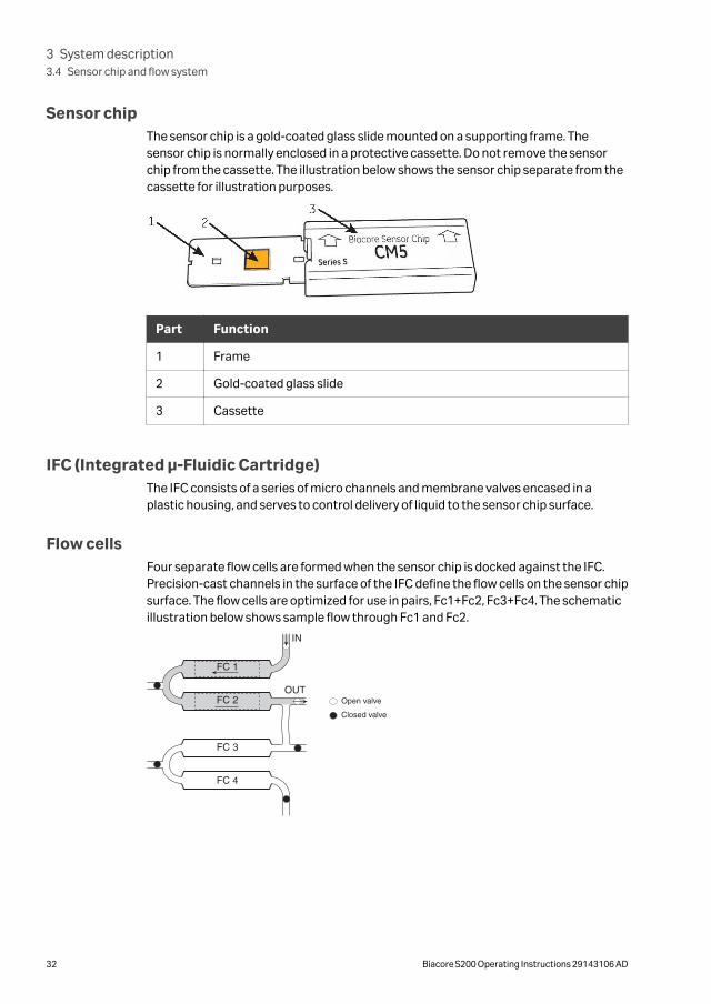
Sensor chipThe sensor chip is a gold-coated glass slide mounted on a supporting frame. Thesensor chip is normally enclosed in a protective cassette. Do not remove the sensorchip from the cassette. The illustration below shows the sensor chip separate from thecassette for illustration purposes.
Part Function
1 Frame
2 Gold-coated glass slide
3 Cassette
IFC (Integrated µ-Fluidic Cartridge)The IFC consists of a series of micro channels and membrane valves encased in aplastic housing, and serves to control delivery of liquid to the sensor chip surface.
Flow cellsFour separate flow cells are formed when the sensor chip is docked against the IFC.Precision-cast channels in the surface of the IFC define the flow cells on the sensor chipsurface. The flow cells are optimized for use in pairs, Fc1+Fc2, Fc3+Fc4. The schematicillustration below shows sample flow through Fc1 and Fc2.
3 System description3.4 Sensor chip and flow system
32 Biacore S200 Operating Instructions 29143106 AD
3.5 Temperature control
IntroductionSPR measurements are sensitive to changes in temperature. It is important that aconstant temperature is maintained at the sensor chip surface throughout the run.
Analysis temperatureThe detection area housing the sensor chip is maintained at a precisely controlledtemperature (range 4°C to 45°C, not more than 20°C below ambient temperature).Runs will not start automatically if the temperature at the sensor surface is not stable.You can choose to ignore the condition or wait for the temperature to stabilize. TheTemperature indicator on the instrument front panel flashes if the analysis tempera-ture is not stable.
Sample compartment temperatureThe sample compartment is maintained at a temperature that may be set from 4°C to45°C, not more than 15°C below ambient temperature.
The sample compartment temperature is set independently of the analysis tempera-ture: injected samples have sufficient time in the needle and IFC to equilibrate to theanalysis temperature regardless of sample compartment temperature.
NOTICE
The system does not wait for the sample compartment tempera-ture to stabilize. The Temperature indicator and screen displayshow the analysis temperature, not the sample compartmenttemperature.
Condensation may occasionally drip from the instrument during long runs at lowtemperatures, particularly if ambient humidity is high. This is normal and does notaffect instrument operation.
3 System description3.5 Temperature control
Biacore S200 Operating Instructions 29143106 AD 33
3.6 Control systemBiacore S200 Control Software is a complete software for control and supervision ofBiacore S200.
Biacore S200 Evaluation Software is a stand-alone software for evaluation of resultsobtained from Biacore S200. The software is normally installed on the same computeras the Biacore S200 Control Software, although connection to the instrument is notrequired for using Biacore S200 Evaluation Software.
3 System description3.6 Control system
34 Biacore S200 Operating Instructions 29143106 AD
4 Installation
About this chapterThis chapter describes site requirements and preparations necessary to performbefore installation of the Biacore S200 system.
In addition, instructions are included for moving the Biacore S200 system within thelab or to another building.
NOTICEBiacore S200 is prepared and installed by Cytiva personnel.Contact Cytiva if you require re-installation at a new site.
In this chapter
Section See page
4.1 Site requirements 36
4.2 Unpacking, assembly and transport 39
4.3 Connections 40
4 Installation
Biacore S200 Operating Instructions 29143106 AD 35
4.1 Site requirements
WARNING
A fume hood or similar ventilation system shall be installed whenflammable or noxious substances are used.
WARNING
Explosion hazard. To avoid building up an explosive atmospherewhen using flammable liquids, make sure that the room ventilationmeets the local requirements.
Space requirementsThe size of the instrument is indicated in the illustration below. At least 20 cm clear-ance is required on all sides of the instrument to allow adequate air circulation. Space isalso required for the PC beside the instrument. The laboratory bench must be stableand able to support the weight of the instrument.
4 Installation4.1 Site requirements
36 Biacore S200 Operating Instructions 29143106 AD
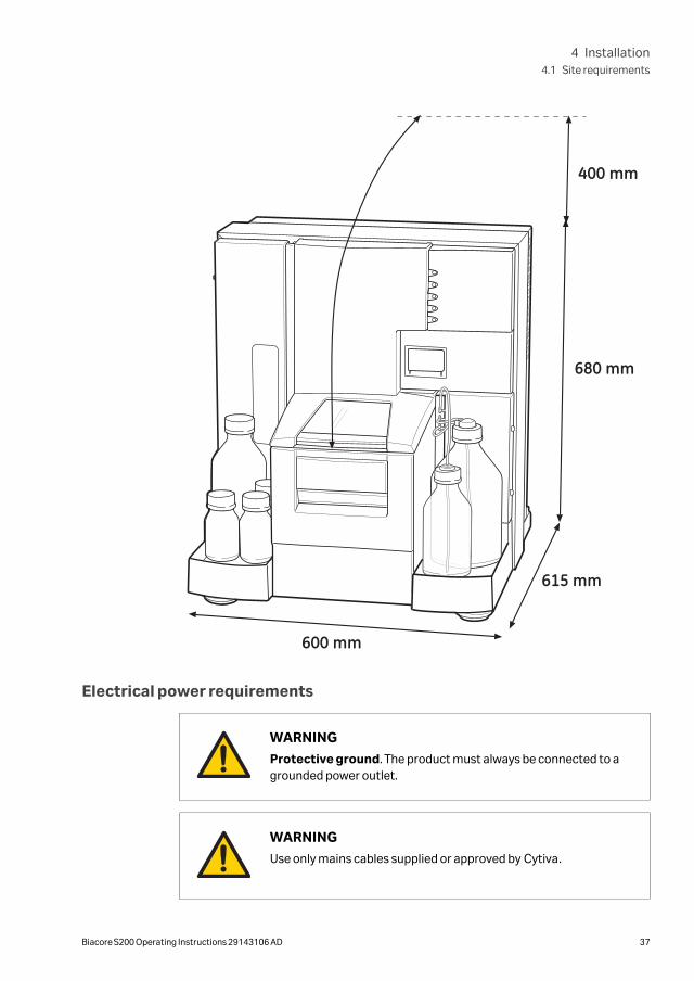
400 mm
680 mm
615 mm
600 mm
Electrical power requirements
WARNING
Protective ground. The product must always be connected to agrounded power outlet.
WARNING
Use only mains cables supplied or approved by Cytiva.
4 Installation4.1 Site requirements
Biacore S200 Operating Instructions 29143106 AD 37
WARNING
Do not block the rear or side panels of the instrument. The powerswitch must always be easy to access. The power cord must alwaysbe easy to disconnect.
The instrument requires mains power outlets with protective earth as specified in thetable below.
Parameter Specification
Supply voltage 100 to 240 V~
Frequency 50/60 Hz
Maximum power 400 VA
Transient overvoltages Overvoltage category II
Environmental requirementsThe following general requirements must be fulfilled:
• The room must have exhaust ventilation
• The instrument should not be exposed to direct sunlight
• Dust in the atmosphere should be kept to a minimum
The installation site must comply with the following specifications:
Parameter Specification
Allowed location Indoor use only
Ambient temperature, operation 18°C to 33°C
Max. relative humidity, operation 80% RH, non-condensing, up to 31°C.
Decreasing linearly to 50% RH at 40°C.
Ambient temperature, transportation/storage
-25°C to 60°C
Altitude, operation Up to 2000 m
Pollution degree of the intendedenvironment
Pollution degree 2
Avoid placing the system adjacent to heaters or air conditioners.
Condensation may occur in the sample compartment at high ambient humidity. This isnormal and does not indicate any malfunction.
4 Installation4.1 Site requirements
38 Biacore S200 Operating Instructions 29143106 AD
4.2 Unpacking, assembly and transport
UnpackingBiacore S200 will be unpacked by Cytiva personnel.
Check the equipment for any apparent damage before starting installation. Documentany damage carefully and contact your Cytiva representative.
Contact Cytiva if you need to re-pack Biacore S200 for storage or transport.
AssemblyBiacore S200 requires no special assembly other than that performed by Cytivapersonnel during installation.
TransportTo avoid damage, the optical unit in Biacore S200 must be secured before transportover more than limited distances within the laboratory. Contact Cytiva for assistance.
CAUTION
Heavy object. Use proper lifting equipment, or use three or morepersons when moving the instrument. All lifting and moving mustbe performed in accordance with local regulations.
CAUTION
Wear protective shoes with steel toecaps when moving the instru-ment to protect against falling objects.
CAUTION
Make sure that hands or fingers are not trapped under the instru-ment when the instrument is lifted or moved.
4 Installation4.2 Unpacking, assembly and transport
Biacore S200 Operating Instructions 29143106 AD 39
4.3 Connections
NOTICE
Do not turn on the mains power switches before all connectionsare made.
Connect the instrument to thecomputer
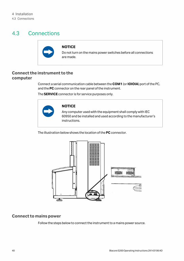
Connect a serial communication cable between the COM1 (or IOIOIA) port of the PC,and the PC connector on the rear panel of the instrument.
The SERVICE connector is for service purposes only.
NOTICE
Any computer used with the equipment shall comply with IEC60950 and be installed and used according to the manufacturer’sinstructions.
The illustration below shows the location of the PC connector.
Connect to mains power
Follow the steps below to connect the instrument to a mains power source.
4 Installation4.3 Connections
40 Biacore S200 Operating Instructions 29143106 AD
Step Action
1 Connect the mains power cord delivered with the instrument, to the MAINSINLET connector on the rear panel (see Mains power switch, on page 27).Connect the other end to a mains outlet with protective earth.
2 Check that any mains voltage selectors on the PC and peripheral equipmentare set correctly.
3 Install the PC and peripheral equipment according to the respective instruc-tion manuals.
WARNING
Do not block the rear or side panels of the instrument. The powerswitch must always be easy to access. The power cord must alwaysbe easy to disconnect.
4 Installation4.3 Connections
Biacore S200 Operating Instructions 29143106 AD 41
5 Operation
About this chapterThis chapter gives instructions on how to operate the product in a safe way.
In this chapter
Section See page
5.1 Starting the system 44
5.2 Preparing the instrument 45
5.3 Ejecting the rack tray 49
5.4 Adjusting the rack tray 51
5.5 Preparing samples and reagents 52
5.6 Changing reagent racks 54
5.7 Installing the rack tray 55
5.8 Starting and finishing a run 56
Safety precautions
WARNINGAlways wear appropriate protective clothing and equipment duringoperation and maintenance of the Biacore S200 system. Userequired safety equipment when handling hazardous substances.
WARNING
Do not use any accessories not supplied or recommended byCytiva.
5 Operation
42 Biacore S200 Operating Instructions 29143106 AD
WARNING
Handle bottles carefully. Accidental breakage of buffer or waterbottles may cause flooding of the bottle tray, and liquid may comeinto contact with electrical circuits, causing electric shock and/orfire hazards.
WARNING
Liquids in the buffer bottles or tubing may be toxic or flammable ormay cause chemical burns or irritation to skin and eyes. Takeappropriate precautions in the event of bottle breakage, accidentalspillage and insecure fitting of tubings to bottles.
WARNING
Waste liquids may contain hazardous or flammable substances.Take appropriate precautions to avoid spillage of hazardous waste.
CAUTIONBiacore S200 systems that are used with toxic or hazardoussubstances shall be marked in accordance with local laws andregulations.
CAUTION
Ensure that all fluidic tubes are secured and properly connected orsealed at both ends before, during and after operation.
CAUTION
Waste tubes and containers shall be secured and sealed to preventaccidental spillage.
CAUTION
Accidental breakage of glass bottles may leave sharp fragmentsand splinters that can cause cuts and abrasions.
5 Operation
Biacore S200 Operating Instructions 29143106 AD 43
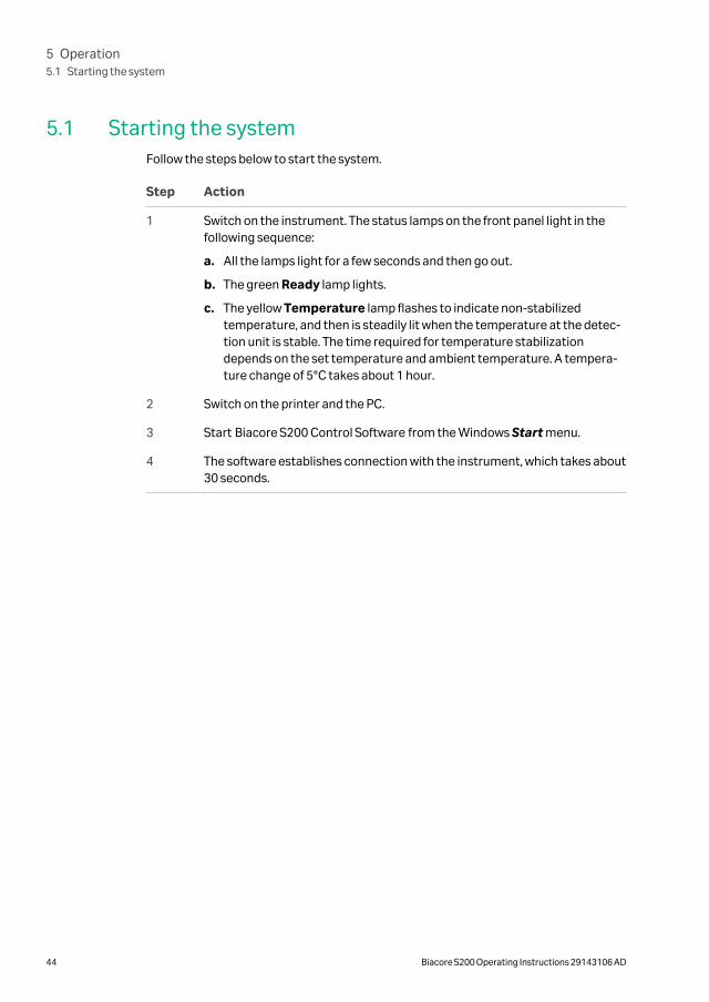
5.1 Starting the systemFollow the steps below to start the system.
Step Action
1 Switch on the instrument. The status lamps on the front panel light in thefollowing sequence:
a. All the lamps light for a few seconds and then go out.
b. The green Ready lamp lights.
c. The yellow Temperature lamp flashes to indicate non-stabilizedtemperature, and then is steadily lit when the temperature at the detec-tion unit is stable. The time required for temperature stabilizationdepends on the set temperature and ambient temperature. A tempera-ture change of 5°C takes about 1 hour.
2 Switch on the printer and the PC.
3 Start Biacore S200 Control Software from the Windows Start menu.
4 The software establishes connection with the instrument, which takes about30 seconds.
5 Operation5.1 Starting the system
44 Biacore S200 Operating Instructions 29143106 AD
5.2 Preparing the instrument
Prepare buffers
NOTICE
Always keep a high standard of hygiene in the solutions used.Prepare fresh buffer before each run.
Using standard buffers
Standard buffers are available from Cytiva as stock solutions1. To prepare runningbuffer, dilute the stock solution with distilled and filtered water. Available buffer solu-tions include HEPES-buffered saline (HBS) and phosphate-buffered saline (PBS).
Phosphate buffer should not be used for interaction systems that require Ca2+ , sincecalcium phosphate will precipitate at very low concentrations of Ca2+ .
Preparing your own buffers
All buffers used in Biacore S200, both as running buffer and for sample and reagentpreparation, should be filtered through a 0.22 µm filter.
Including a surfactant in the buffer can reduce non-specific adsorption of proteins tothe autosampler tube and the IFC channels. Surfactant P20 is available from Cytiva.You may omit surfactant if your sample is detergent-sensitive. However, you may thenwant to clean the flow system more frequently (see Cleaning and disinfecting the flowsystem, on page 63 for more information).
Insert the sensor chip
Before Biacore S200 can be used, a sensor chip must be docked in the instrument.Follow the steps below to dock a sensor chip.
Step Action
1 Click the Insert Chip button in the Tools workspace.
1 Buffers in 200 mL ready-to-use packs are not recommended for use with Biacore S200.
5 Operation5.2 Preparing the instrument
Biacore S200 Operating Instructions 29143106 AD 45
Step Action
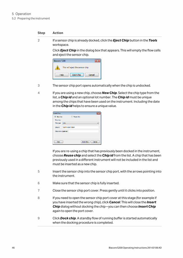
2 If a sensor chip is already docked, click the Eject Chip button in the Toolsworkspace.
Click Eject Chip in the dialog box that appears. This will empty the flow cellsand eject the sensor chip.
3 The sensor chip port opens automatically when the chip is undocked.
4 If you are using a new chip, choose New Chip. Select the chip type from thelist, a Chip id and an optional lot number. The Chip id must be uniqueamong the chips that have been used on the instrument. Including the datein the Chip id helps to ensure a unique value.
If you are re-using a chip that has previously been docked in the instrument,choose Reuse chip and select the Chip id from the list. A chip that has beenpreviously used in a different instrument will not be included in the list andmust be inserted as a new chip.
5 Insert the sensor chip into the sensor chip port, with the arrows pointing intothe instrument.
6 Make sure that the sensor chip is fully inserted.
7 Close the sensor chip port cover. Press gently until it clicks into position.
8 If you need to open the sensor chip port cover at this stage (for example ifyou have inserted the wrong chip), click Cancel. This will close the InsertChip dialog without docking the chip—you can then choose Insert Chipagain to open the port cover.
9 Click Dock chip. A standby flow of running buffer is started automaticallywhen the docking procedure is completed.
5 Operation5.2 Preparing the instrument
46 Biacore S200 Operating Instructions 29143106 AD
Set up the liquid system
Follow the steps below to set up the liquid system.
NOTICE
Always use fresh water. Replace water before each run, or at leastevery 48 hours. Do not run the system without water.
Step Action
1 Open the right pump compartment door and make sure that the clamp ofthe peristaltic pump is properly fastened: the lever should be in a verticalposition.
2 Fill a suitable bottle with running buffer. Make sure that the bottle is cleanbefore use. Fit a cap with gasket on to the bottle and place it on the buffertray. Insert the tube marked A through the cap, into the running bufferbottle.
3 If you plan to use more than one buffer, fill up to three additional bottles withthe required buffers. Fit caps with gaskets on to the bottles and place themon the buffer tray. Insert the tubes marked B, C and D into the bottles.
5 Operation5.2 Preparing the instrument
Biacore S200 Operating Instructions 29143106 AD 47
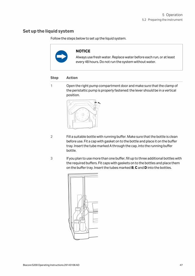
Step Action
4 Place unused buffer tubing in the holder inside the pump compartmentdoor.
5 Place a 2-liter bottle for waste solution on the waste and water tray. Fit thecap carrying the waste tubes on to the bottle. Tighten the tube fittings byhand. Do not use a smaller bottle for waste.
6 Fill a 500 mL bottle with distilled and filtered water. Fit a cap with gasket andplace it on the waste and water tray. Insert the water tube into the waterbottle.
7 Prime the flow system using Prime or MultiPrime from the Tools work-space or using the option in the method, to ensure that the flow system isequilibrated with fresh buffer.
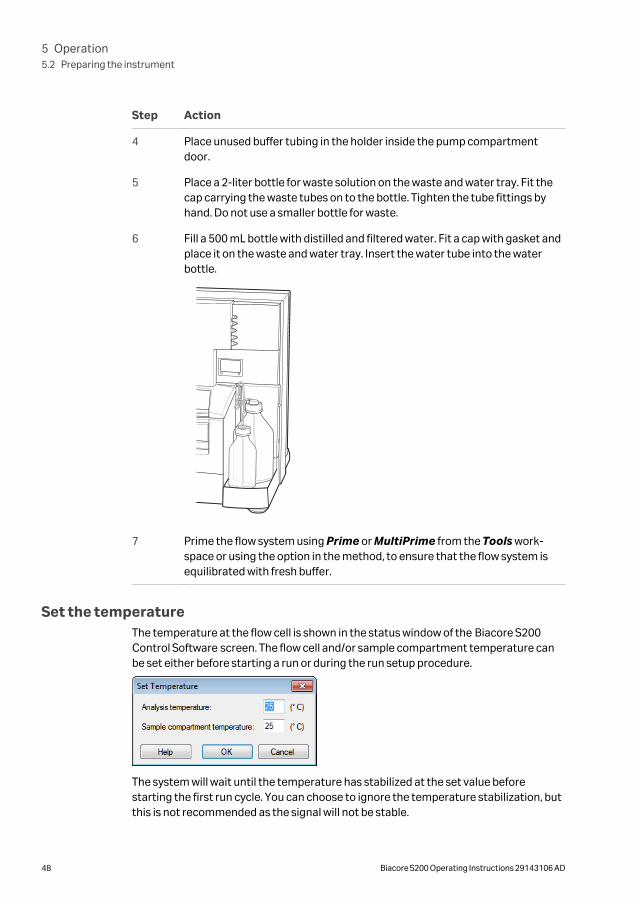
Set the temperatureThe temperature at the flow cell is shown in the status window of the Biacore S200Control Software screen. The flow cell and/or sample compartment temperature canbe set either before starting a run or during the run setup procedure.
The system will wait until the temperature has stabilized at the set value beforestarting the first run cycle. You can choose to ignore the temperature stabilization, butthis is not recommended as the signal will not be stable.
5 Operation5.2 Preparing the instrument
48 Biacore S200 Operating Instructions 29143106 AD
5.3 Ejecting the rack tray
IntroductionThe removable rack tray carries one microplate and one reagent rack, and is mountedon the rack tray carriage in the sample compartment. The combined sample andreagent rack is mounted directly on the rack tray carriage.
The rack tray (or the sample and reagent rack) can be ejected in three situations:
• before a run, when preparing samples and reagents,
• during setup of a run,
• during a manual run.
Ejecting the rack tray before a run
Follow the steps below to eject the rack tray before a run.
Step Action
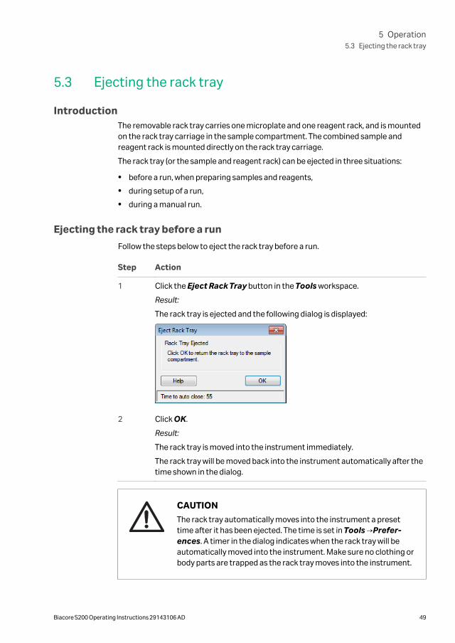
1 Click the Eject Rack Tray button in the Tools workspace.
Result:
The rack tray is ejected and the following dialog is displayed:
2 Click OK.
Result:
The rack tray is moved into the instrument immediately.
The rack tray will be moved back into the instrument automatically after thetime shown in the dialog.
CAUTION
The rack tray automatically moves into the instrument a presettime after it has been ejected. The time is set in Tools →Prefer-ences. A timer in the dialog indicates when the rack tray will beautomatically moved into the instrument. Make sure no clothing orbody parts are trapped as the rack tray moves into the instrument.
5 Operation5.3 Ejecting the rack tray
Biacore S200 Operating Instructions 29143106 AD 49
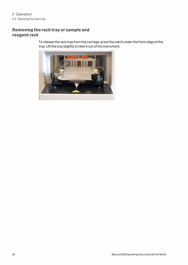
Removing the rack tray or sample andreagent rack
To release the rack tray from the carriage, press the catch under the front edge of thetray. Lift the tray slightly to take it out of the instrument.
5 Operation5.3 Ejecting the rack tray
50 Biacore S200 Operating Instructions 29143106 AD
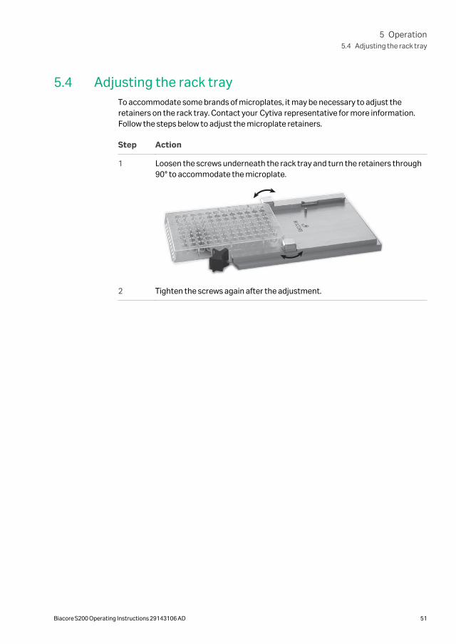
5.4 Adjusting the rack trayTo accommodate some brands of microplates, it may be necessary to adjust theretainers on the rack tray. Contact your Cytiva representative for more information.Follow the steps below to adjust the microplate retainers.
Step Action
1 Loosen the screws underneath the rack tray and turn the retainers through90° to accommodate the microplate.
2 Tighten the screws again after the adjustment.
5 Operation5.4 Adjusting the rack tray
Biacore S200 Operating Instructions 29143106 AD 51
5.5 Preparing samples and reagents
In a microplate
Follow the steps below to prepare samples and reagents in a microplate.
Step Action
1 Dispense the samples and reagents into the microplate and/or vials. Checkthat there are no air bubbles trapped at the bottom of the microplate wells. Itis particularly easy to trap air bubbles at the bottom of the wells in 384-wellmicroplates.
2 Cover the used sample wells in microplates with recommended adhesivefoil, available from Cytiva and cap any vials used. This prevents evaporationfrom the samples during analysis.
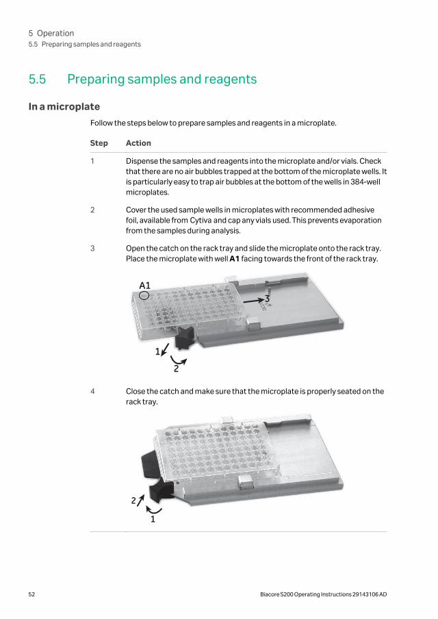
3 Open the catch on the rack tray and slide the microplate onto the rack tray.Place the microplate with well A1 facing towards the front of the rack tray.
1
2
3A1
4 Close the catch and make sure that the microplate is properly seated on therack tray.
1
2
5 Operation5.5 Preparing samples and reagents
52 Biacore S200 Operating Instructions 29143106 AD
In a reagent rack
Follow the steps below to prepare samples and reagents in a reagent rack (or sampleand reagent rack).
Step Action
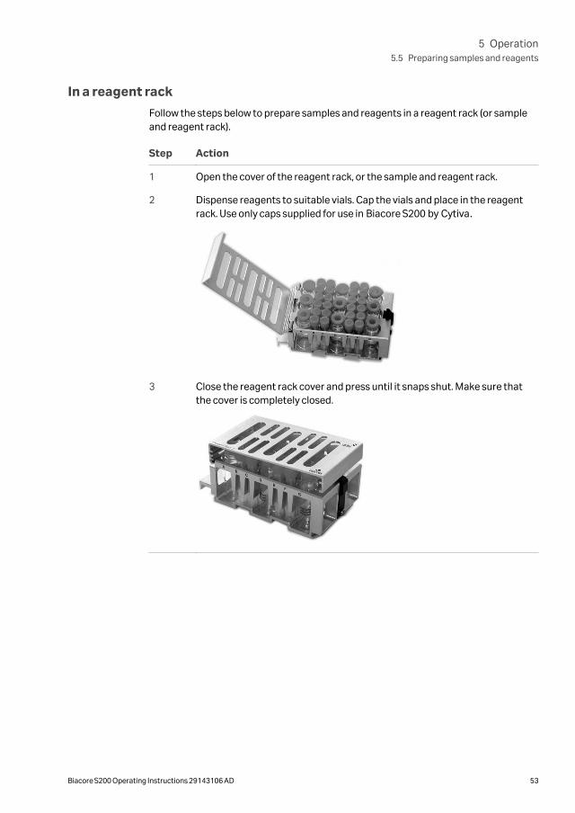
1 Open the cover of the reagent rack, or the sample and reagent rack.
2 Dispense reagents to suitable vials. Cap the vials and place in the reagentrack. Use only caps supplied for use in Biacore S200 by Cytiva.
3 Close the reagent rack cover and press until it snaps shut. Make sure thatthe cover is completely closed.
5 Operation5.5 Preparing samples and reagents
Biacore S200 Operating Instructions 29143106 AD 53
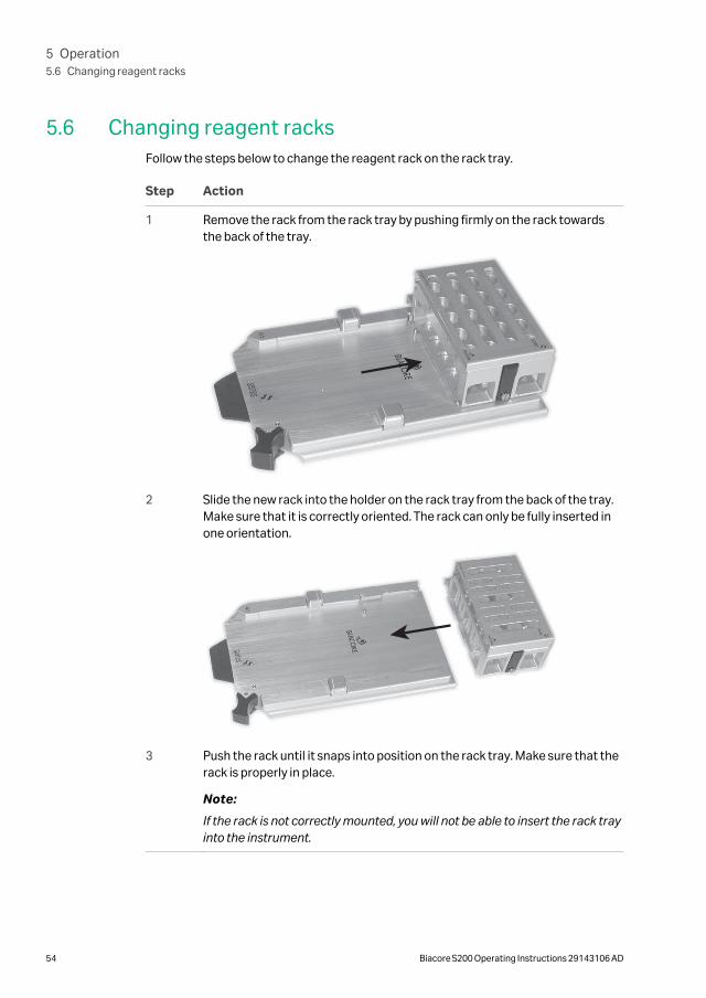
5.6 Changing reagent racksFollow the steps below to change the reagent rack on the rack tray.
Step Action
1 Remove the rack from the rack tray by pushing firmly on the rack towardsthe back of the tray.
2 Slide the new rack into the holder on the rack tray from the back of the tray.Make sure that it is correctly oriented. The rack can only be fully inserted inone orientation.
3 Push the rack until it snaps into position on the rack tray. Make sure that therack is properly in place.
Note:
If the rack is not correctly mounted, you will not be able to insert the rack trayinto the instrument.
5 Operation5.6 Changing reagent racks
54 Biacore S200 Operating Instructions 29143106 AD
5.7 Installing the rack trayFollow the steps below to install the rack tray or sample and reagent rack.
Step Action
1 If the rack tray port is not open when you are ready to install the rack tray,eject the rack tray carriage.
2 Insert the rack tray. Press gently until the rack tray snaps into place.
3 The rack tray carriage automatically moves into the instrument a presettime after it has been ejected. The time is set in Tools →Preferences. ClickOK in the Eject Rack Tray dialog to move the rack tray into the instrumentimmediately.
CAUTION
The rack tray automatically moves into the instrument apreset time after it has been ejected. The time is set inTools →Preferences. A timer in the dialog indicateswhen the rack tray will be automatically moved into theinstrument. Make sure no clothing or body parts aretrapped as the rack tray moves into the instrument.
Note: The rack tray cannot be accessed during an automated run.
5 Operation5.7 Installing the rack tray
Biacore S200 Operating Instructions 29143106 AD 55
5.8 Starting and finishing a run
Start a runWhen docking of the sensor chip is ready, a standby flow of running buffer is started.
For details of how to start a run, refer to the Biacore S200 Software Handbook.
Standby modeWhen a run is completed, the instrument is automatically placed in standby mode. Acontinuous low flow of buffer (using buffer tube A) is maintained through the flowsystem to prevent accumulation of buffer residues.
The default standby period is 7 days. Liquid consumption during standby is approxi-mately 65 mL per 24 hours.
NOTICE
As a general recommendation use distilled and filtered water forstandby to minimize salt deposits. However, if an immobilizedsensor chip is docked and will be used for analysis later, buffer maybe used to protect the ligand on the sensor surface.
Wash buffer tubingUse the maintenance tool Wash Buffer Tubing when you change from bufferscontaining substances that tend to adsorb to the tubing, e.g. detergent or serumalbumin.
If you have used buffer tubes B, C or D and do not plan to use them in coming runs, runthe maintenance tool Empty Buffer Tubing to wash and empty the buffer tubing,then place unused tubes in the holder in the left pump compartment.
ShutdownIf you want to shut down the instrument completely, see Section 6.5 Shutting down thesystem, for instructions.
5 Operation5.8 Starting and finishing a run
56 Biacore S200 Operating Instructions 29143106 AD
6 Maintenance
About this chapterThis chapter summarizes user maintenance procedures. If more extensive service isrequired, please contact your Cytiva service representative. Complete the appropriateHealth and Safety Declaration Form before contacting your local service representa-tive or returning the system for maintenance or service.
Several maintenance operations are performed using software tools with on-screeninstructions in English. See Appendix A Software tool texts, on page 103 for theseinstructions in your local language.
WARNING
All service and repairs, with the exception of operations explicitlydescribed in the user documentation, must be carried out bypersonnel authorized by Cytiva. Do not open any covers or replaceany parts unless specifically stated in the user documentation.
WARNINGAlways wear appropriate protective clothing and equipment duringoperation and maintenance of the Biacore S200 system. Userequired safety equipment when handling hazardous substances.
CAUTION
Pinch risk. Take care that fingers are not trapped by moving partson the instrument.
6 Maintenance
Biacore S200 Operating Instructions 29143106 AD 57
In this chapter
Section See page
6.1 Maintenance preparations 59
6.2 Maintenance summary 60
6.3 User maintenance operations 62
6.4 User service operations 66
6.5 Shutting down the system 72
6.6 Replacing the mains fuses 74
6 Maintenance
58 Biacore S200 Operating Instructions 29143106 AD

6.1 Maintenance preparations
ImportantMake sure that the BIAmaintenance Kit type 2 is available before starting maintenanceprocedures.
Regular maintenance of Biacore S200 is essential for reliable results. It is important tokeep the instrument free from contamination such as microbial growth and adsorbedproteins in the liquid handling system.
Regular checks and maintenance should be done according to the schedules below.You will be reminded of the need for Desorb and Desorb and Sanitize procedures viaa maintenance scheduler in the Control Software. Do not ignore maintenancereminders.
Safety precautions
WARNING
If the instrument may be contaminated with biohazards, decon-taminate the instrument before performing maintenance on anyinstrument parts. Contact your local service representative forfurther information about decontamination procedures.
WARNING
Concentrated BIAdisinfectant solution is corrosive. The solutionshould be diluted shortly before use as described in the Instruc-tions for Use provided with the product.
NOTICE
Some maintenance procedures will destroy the ligand on aprepared sensor chip. Always use the separate Sensor Chip Main-tenance that is included in the Maintenance Kit unless otherwisestated.
NOTICE
Do not use BIAdesorb solution 1 at analysis temperatures below20°C. BIAdesorb solution 1 precipitates at low temperatures.
6 Maintenance6.1 Maintenance preparations
Biacore S200 Operating Instructions 29143106 AD 59
6.2 Maintenance summary
User maintenance operationsRegular checks and maintenance should be done according to the schedule below.
Interval Action
Daily/after each run Empty the waste bottle
Weekly Inspect tube fittings and pumps for possible leaks
Clean the flow system (Desorb)
Monthly Clean the instrument cover
Clean and disinfect the flow system (Desorb and Sanitize)
Inspect the needle and the liquid supply block
Inspect the sample compartment, look for signs of flooding
Run System Check
User service operationsUse the software tools listed in the table below for user service operations.
Tool Description
System Check Always run System Check before calling a Cytiva servicerepresentative. The results of System Check may help indiagnosing and solving your problems.
Software ProblemReport
Run this tool if you experience problems with Biacore S200Software which do not have a readily apparent solution.
Flow SystemWash
This tool will flush the flow system with buffer at a high flowrate to clear obstructions such as aggregated particles.
Superclean This tool can be used for extensive cleaning if the Desorband Sanitize procedure is not sufficient to clean the flowsystem.
Required materialsMaterials required for user maintenance and service operations are summarizedbelow.
BIAmaintenance Kit type 2
6 Maintenance6.2 Maintenance summary
60 Biacore S200 Operating Instructions 29143106 AD
The contents of the kit are listed below.
Solution/item Specification
BIAdesorb solution 1 0.5% (w/v) sodium dodecyl sulfate (SDS), two bottlesof 95 mL
BIAdesorb solution 2 50 mM glycine pH 9.5, two bottles of 95 mL
BIAtest solution 14.9% sucrose in HBS-N buffer with 3 mM EDTA, onebottle of 65 mL
BIAdisinfectant solution(conc.)
Sodium hypochlorite with 8% to 12% active chlorine,three bottles of 10 mL
BIAnormalizing solution 70% (w/w) glycerol, one bottle of 90 mL
HBS-N buffer 10× One bottle of 50 mL
Sensor Chip Maintenance One sensor chip
All solutions except BIAdesorb solution 1 should be stored at +4°C to 8°C. BIAdesorbsolution 1 should be stored at room temperature.
Additional materials
In addition to the Maintenance Kit you will need the following materials:
• Distilled and filtered water
• 70% (v/v) ethanol
• Clean, lint-free wipes
• Series S Sensor Chip CM5
Preventive maintenanceTo ensure correct performance of Biacore S200, preventive maintenance should bedone regularly by a qualified Cytiva service representative. During the maintenancevisit, worn parts are replaced and all vital modules of the system are tested.
The following components are always replaced:
• IFC
• Opto-interface
• Syringe pumps
• Peristaltic pump tubing
6 Maintenance6.2 Maintenance summary
Biacore S200 Operating Instructions 29143106 AD 61
6.3 User maintenance operations
Cleaning the instrument
WARNING
Liquids in the buffer bottles or tubing may be toxic or flammable ormay cause chemical burns or irritation to skin and eyes. Takeappropriate precautions in the event of bottle breakage, accidentalspillage and insecure fitting of tubings to bottles.
If necessary, clean the cover of the processing unit with a moist cloth. Use water or amild detergent.
The buffer tray and the waste and water tray can be removed for cleaning.
If necessary, clean the waste bottle cap as follows:
Step Action
1 Unscrew the cap from the waste bottle.
2 Loosen the tube fittings and remove the tubes from the cap.
3 Rinse the cap in deionized water.
4 Re-attach the tubes to the cap and tighten the fittings firmly.
Cleaning before plannedmaintenance/service
To ensure the protection and safety of service personnel, all equipment and work areasmust be clean and free of any hazardous contaminants before a Service Engineerstarts maintenance work.
Please complete the checklist in the On Site Service Health and Safety DeclarationForm or the Health and Safety Declaration Form for Product Return or Servicing,depending on whether the instrument is going to be serviced on site or returned forservice, respectively.
Health and safety declaration formsHealth and safety declaration forms are available for copying or printing in the Refer-ence information chapter of this manual, or on digital media supplied with the userdocumentation.
6 Maintenance6.3 User maintenance operations
62 Biacore S200 Operating Instructions 29143106 AD
Cleaning and disinfecting the flowsystem
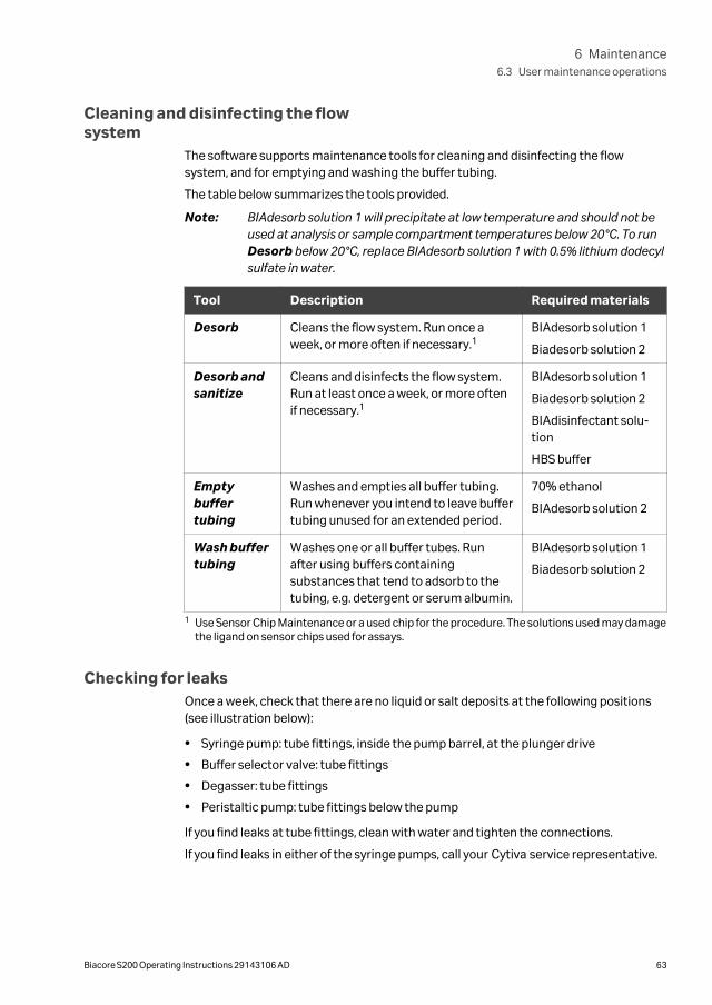
The software supports maintenance tools for cleaning and disinfecting the flowsystem, and for emptying and washing the buffer tubing.
The table below summarizes the tools provided.
Note: BIAdesorb solution 1 will precipitate at low temperature and should not beused at analysis or sample compartment temperatures below 20°C. To runDesorb below 20°C, replace BIAdesorb solution 1 with 0.5% lithium dodecylsulfate in water.
Tool Description Required materials
Desorb Cleans the flow system. Run once aweek, or more often if necessary.1
BIAdesorb solution 1
Biadesorb solution 2
Desorb andsanitize
Cleans and disinfects the flow system.Run at least once a week, or more oftenif necessary.1
BIAdesorb solution 1
Biadesorb solution 2
BIAdisinfectant solu-tion
HBS buffer
Emptybuffertubing
Washes and empties all buffer tubing.Run whenever you intend to leave buffertubing unused for an extended period.
70% ethanol
BIAdesorb solution 2
Wash buffertubing
Washes one or all buffer tubes. Runafter using buffers containingsubstances that tend to adsorb to thetubing, e.g. detergent or serum albumin.
BIAdesorb solution 1
Biadesorb solution 2
1 Use Sensor Chip Maintenance or a used chip for the procedure. The solutions used may damagethe ligand on sensor chips used for assays.
Checking for leaksOnce a week, check that there are no liquid or salt deposits at the following positions(see illustration below):
• Syringe pump: tube fittings, inside the pump barrel, at the plunger drive
• Buffer selector valve: tube fittings
• Degasser: tube fittings
• Peristaltic pump: tube fittings below the pump
If you find leaks at tube fittings, clean with water and tighten the connections.
If you find leaks in either of the syringe pumps, call your Cytiva service representative.
6 Maintenance6.3 User maintenance operations
Biacore S200 Operating Instructions 29143106 AD 63
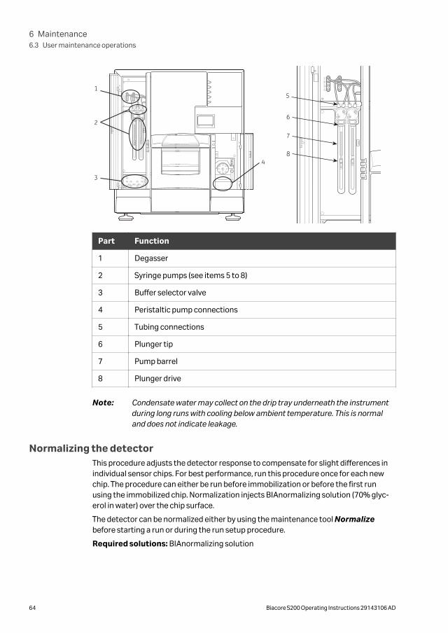
1
2
3
4
5
6
7
8
Part Function
1 Degasser
2 Syringe pumps (see items 5 to 8)
3 Buffer selector valve
4 Peristaltic pump connections
5 Tubing connections
6 Plunger tip
7 Pump barrel
8 Plunger drive
Note: Condensate water may collect on the drip tray underneath the instrumentduring long runs with cooling below ambient temperature. This is normaland does not indicate leakage.
Normalizing the detectorThis procedure adjusts the detector response to compensate for slight differences inindividual sensor chips. For best performance, run this procedure once for each newchip. The procedure can either be run before immobilization or before the first runusing the immobilized chip. Normalization injects BIAnormalizing solution (70% glyc-erol in water) over the chip surface.
The detector can be normalized either by using the maintenance tool Normalizebefore starting a run or during the run setup procedure.
Required solutions: BIAnormalizing solution
6 Maintenance6.3 User maintenance operations
64 Biacore S200 Operating Instructions 29143106 AD

NOTICE
Run Normalize with the sensor chip that will be used for the run.Do not use Sensor Chip Maintenance for this purpose.
6 Maintenance6.3 User maintenance operations
Biacore S200 Operating Instructions 29143106 AD 65
6.4 User service operations
IntroductionThe software supports test and service tools for System Check, Software ProblemReport, Flow System Wash, and Superclean.
System CheckThis procedure performs a comprehensive check of system performance, using astandard sucrose solution (BIAtest solution), provided in the Biacore Maintenance Kit.
Use a new Sensor Chip CM5 for this procedure.
Required solutions
BIAtest solution
HBS-N buffer
System Check results
The table below provides some guidelines for interpreting the results of SystemCheck.
Test Likely cause of failure Explanation/Action
Reagentpump
Water
Buffer
Air in injections 1 and 2 The clamp on the upper peristalticpump was not fastened.
Air in single injection Tubing squeezed or not fullyinserted into buffer or water.
Blank injection deviates frombaseline
Deposits in the liquid supply block.
Mixing
Mix 1
Mix 2
Difference
Leaks in syringe pump orother parts of flow system
Call Cytiva service representative.
Flow cell leakage too large Call Cytiva service representative.
Refracto-meter
Fc1
Fc2
Fc3
Fc4
Too low values A new chip was not used. May alsoresult in too large spread in base-line level.
Too high or too low values Wrong buffer.
6 Maintenance6.4 User service operations
66 Biacore S200 Operating Instructions 29143106 AD

Test Likely cause of failure Explanation/Action
Injections
Fc1
Fc2
Fc3
Fc4
Leaks in syringe pump orother parts of flow system
Call Cytiva service representative.
Flow cell leakage too large Call Cytiva service representative.
Noise Drifting baseline A new chip was not used.
Temperature not stable. CallCytiva service representative.
Bufferselector
Buffer A
Buffer B
Buffer C
Buffer D
Tubing in wrong bottles Check that the buffer tubes areinserted in the correct bottles.
Buffer selector not working Call Cytiva service representative.
Leaking syringe pump Call Cytiva service representative.
SupercleanThe Superclean procedure washes the flow system and denatures proteins toincrease their solubility. Warm water is used as running buffer to increase the solubilityof most biomolecules and salt. Required solutions differ according to whether the flowsystem is contaminated with proteins or small molecules.
Run the maintenance tool Desorb and Sanitize followed by Superclean if yoususpect that the Desorb and Sanitize procedure is not sufficient to clean the flowsystem. Total run time is about 1.5 hours.
Required solutions
For cleaning proteins For cleaning small molecules
deionized water at 50°C deionized water at 50°C
1% acetic acid 1% acetic acid
0.2 M sodium bicarbonate 0.2 M sodium bicarbonate
6 M guanidine-HCl 50%DMSO
10 mM HCl 10% DMSO
Use Sensor Chip Maintenance or a used chip for the procedure. The solutions used inthe Superclean procedure may damage the ligand on sensor chips used for assays.
6 Maintenance6.4 User service operations
Biacore S200 Operating Instructions 29143106 AD 67
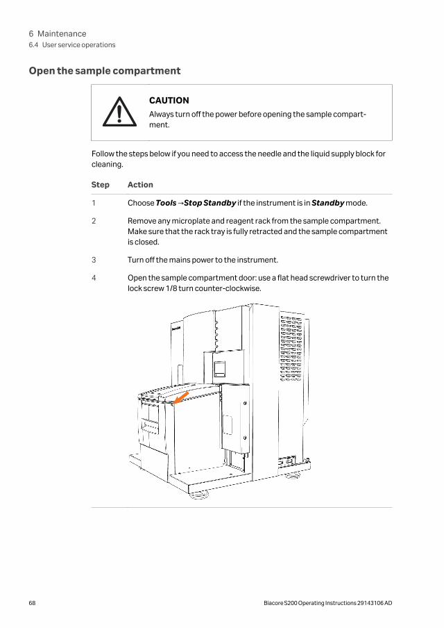
Open the sample compartment
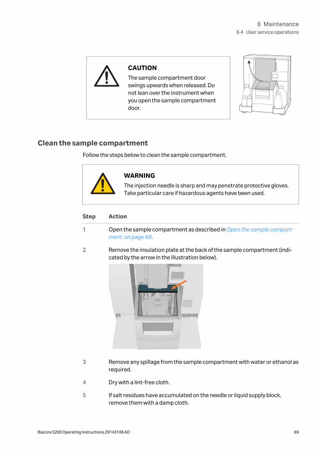
CAUTION
Always turn off the power before opening the sample compart-ment.
Follow the steps below if you need to access the needle and the liquid supply block forcleaning.
Step Action
1 Choose Tools →Stop Standby if the instrument is in Standby mode.
2 Remove any microplate and reagent rack from the sample compartment.Make sure that the rack tray is fully retracted and the sample compartmentis closed.
3 Turn off the mains power to the instrument.
4 Open the sample compartment door: use a flat head screwdriver to turn thelock screw 1/8 turn counter-clockwise.
6 Maintenance6.4 User service operations
68 Biacore S200 Operating Instructions 29143106 AD
CAUTION
The sample compartment doorswings upwards when released. Donot lean over the instrument whenyou open the sample compartmentdoor.
Clean the sample compartment
Follow the steps below to clean the sample compartment.
WARNING
The injection needle is sharp and may penetrate protective gloves.Take particular care if hazardous agents have been used.
Step Action
1 Open the sample compartment as described in Open the sample compart-ment, on page 68.
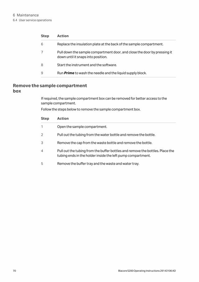
2 Remove the insulation plate at the back of the sample compartment (indi-cated by the arrow in the illustration below).
3 Remove any spillage from the sample compartment with water or ethanol asrequired.
4 Dry with a lint-free cloth.
5 If salt residues have accumulated on the needle or liquid supply block,remove them with a damp cloth.
6 Maintenance6.4 User service operations
Biacore S200 Operating Instructions 29143106 AD 69
Step Action
6 Replace the insulation plate at the back of the sample compartment.
7 Pull down the sample compartment door, and close the door by pressing itdown until it snaps into position.
8 Start the instrument and the software.
9 Run Prime to wash the needle and the liquid supply block.
Remove the sample compartmentbox
If required, the sample compartment box can be removed for better access to thesample compartment.
Follow the steps below to remove the sample compartment box.
Step Action
1 Open the sample compartment.
2 Pull out the tubing from the water bottle and remove the bottle.
3 Remove the cap from the waste bottle and remove the bottle.
4 Pull out the tubing from the buffer bottles and remove the bottles. Place thetubing ends in the holder inside the left pump compartment.
5 Remove the buffer tray and the waste and water tray.
6 Maintenance6.4 User service operations
70 Biacore S200 Operating Instructions 29143106 AD
Step Action
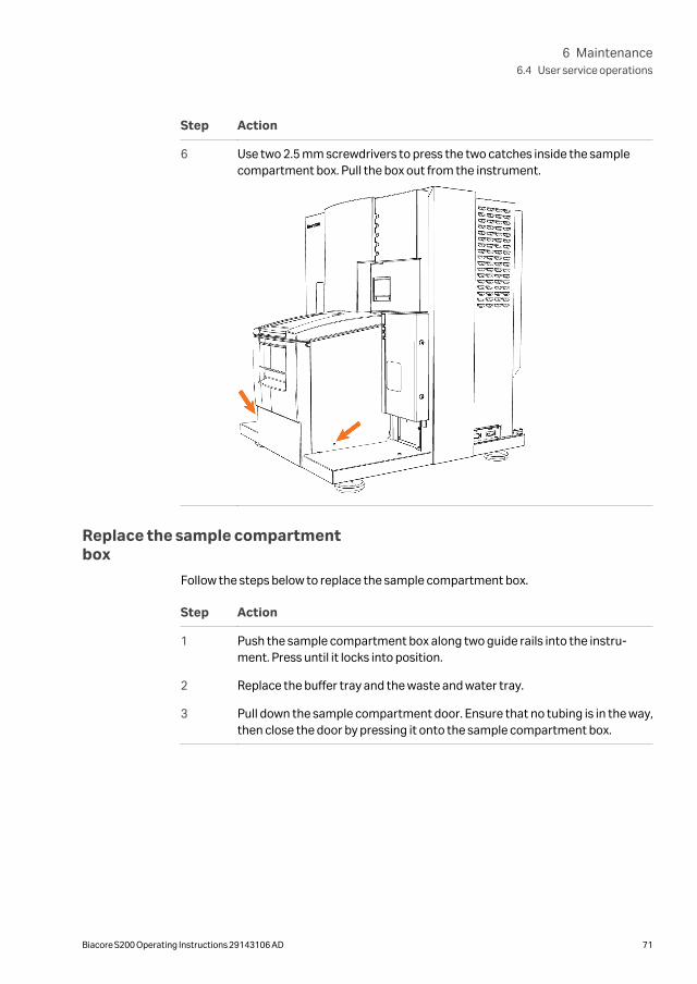
6 Use two 2.5 mm screwdrivers to press the two catches inside the samplecompartment box. Pull the box out from the instrument.
Replace the sample compartmentbox
Follow the steps below to replace the sample compartment box.
Step Action
1 Push the sample compartment box along two guide rails into the instru-ment. Press until it locks into position.
2 Replace the buffer tray and the waste and water tray.
3 Pull down the sample compartment door. Ensure that no tubing is in the way,then close the door by pressing it onto the sample compartment box.
6 Maintenance6.4 User service operations
Biacore S200 Operating Instructions 29143106 AD 71
6.5 Shutting down the system
IntroductionBiacore S200 should normally be left in standby mode when not in use. The instrumentmaintains a low flow of liquid through the flow system. The maximum unattendedstandby period is 7 days.
If the instrument is not to be used for a period of about two weeks or more, run theShutdown procedure to shut the instrument down completely.
StandbyThe instrument enters standby mode automatically at the end of a run. To put theinstrument in standby mode manually, choose Tools →Standby.
NOTICE
As a general recommendation use distilled and filtered water forstandby to minimize salt deposits. However, if an immobilizedsensor chip is docked and will be used for analysis later, buffer maybe used to protect the ligand on the sensor surface.
Before leaving the instrument unattended in standby mode:
• Check that there is sufficient water or buffer for the standby period, and that thebuffer tube marked A is fully inserted into the water bottle. Liquid consumptionduring standby is approximately 65 mL/24 h.
• Check that the waste bottle is emptied.
Shutdown
Follow the steps below to shut down the instrument completely.
Step Action
1 Run Desorb and Sanitize to clean the flow system.
2 Eject the rack tray carriage and remove the rack tray.
3 Prepare a bottle of distilled and filtered water, and a bottle of 70% ethanol.Choose Shutdown from the Tools menu. Follow the instructions on thescreen.
The procedure flushes the flow system and then empties the IFC of liquid.Total run time is about 20 minutes.
6 Maintenance6.5 Shutting down the system
72 Biacore S200 Operating Instructions 29143106 AD
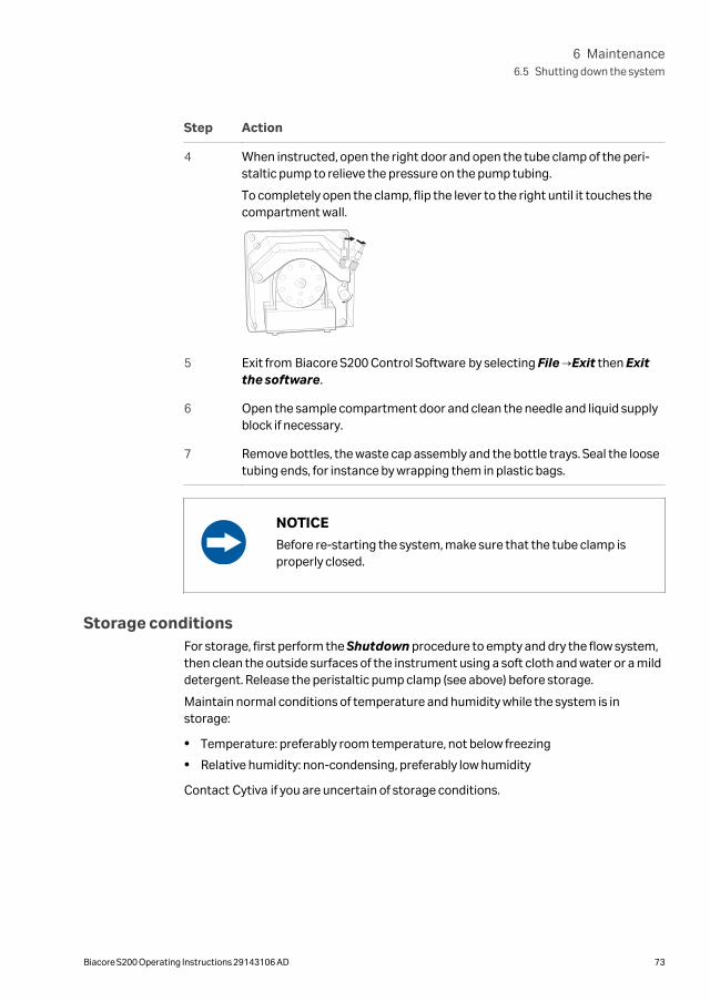
Step Action
4 When instructed, open the right door and open the tube clamp of the peri-staltic pump to relieve the pressure on the pump tubing.
To completely open the clamp, flip the lever to the right until it touches thecompartment wall.
5 Exit from Biacore S200 Control Software by selecting File →Exit then Exitthe software.
6 Open the sample compartment door and clean the needle and liquid supplyblock if necessary.
7 Remove bottles, the waste cap assembly and the bottle trays. Seal the loosetubing ends, for instance by wrapping them in plastic bags.
NOTICE
Before re-starting the system, make sure that the tube clamp isproperly closed.
Storage conditionsFor storage, first perform the Shutdown procedure to empty and dry the flow system,then clean the outside surfaces of the instrument using a soft cloth and water or a milddetergent. Release the peristaltic pump clamp (see above) before storage.
Maintain normal conditions of temperature and humidity while the system is instorage:
• Temperature: preferably room temperature, not below freezing
• Relative humidity: non-condensing, preferably low humidity
Contact Cytiva if you are uncertain of storage conditions.
6 Maintenance6.5 Shutting down the system
Biacore S200 Operating Instructions 29143106 AD 73
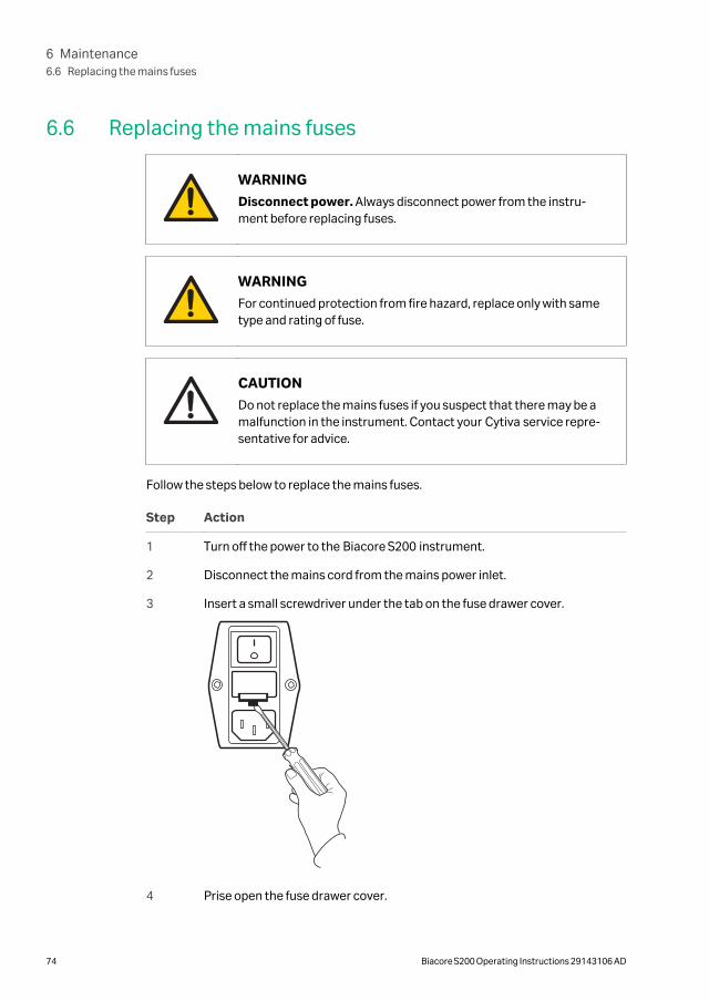
6.6 Replacing the mains fuses
WARNING
Disconnect power. Always disconnect power from the instru-ment before replacing fuses.
WARNING
For continued protection from fire hazard, replace only with sametype and rating of fuse.
CAUTION
Do not replace the mains fuses if you suspect that there may be amalfunction in the instrument. Contact your Cytiva service repre-sentative for advice.
Follow the steps below to replace the mains fuses.
Step Action
1 Turn off the power to the Biacore S200 instrument.
2 Disconnect the mains cord from the mains power inlet.
3 Insert a small screwdriver under the tab on the fuse drawer cover.
4 Prise open the fuse drawer cover.
6 Maintenance6.6 Replacing the mains fuses
74 Biacore S200 Operating Instructions 29143106 AD

Step Action
5 Replace both fuses.
See the instrument product label for fuse ratings.
6 Close the fuse drawer cover and reconnect the mains supply.
6 Maintenance6.6 Replacing the mains fuses
Biacore S200 Operating Instructions 29143106 AD 75

7 Troubleshooting
About this chapterThis chapter gives a brief guide to troubleshooting procedures for problems withBiacore S200.
In this chapter
Section See page
7.1 System-related problems 77
7.2 Assay-related problems 79
7 Troubleshooting
76 Biacore S200 Operating Instructions 29143106 AD
7.1 System-related problems
Instrument hygieneA fundamental requirement for trouble-free operation of Biacore S200 is that thesystem is kept clean and is maintained regularly according to the following guidelines:
• Always use fresh buffer and distilled water. If you prepare your own buffers, filterbuffer and water through a 0.22 µm filter to remove particles. Ready-to-use buffersfrom Cytiva are filtered.
• Follow the recommended maintenance procedures as described in the Mainte-nance chapter of these Operating Instructions. Do not ignore maintenanceschedule reminders.
• If the system is used with particularly “sticky” molecules or complex mixtures suchas serum, clean the flow system thoroughly after each run.
• Leave the system in standby mode with freshly filtered distilled water or buffer whennot in use, or run the Shutdown procedure to empty the flow system. Do not leavethe instrument with liquid standing still in the flow system.
• Do not take the sensor chip out of its protective cassette. Dust or other particles onthe sensor chip surface can seriously interfere with detection.
Instrument considerations
• If the PC does not seem to communicate with the instrument, check that thecommunication cable is properly connected.
• Make sure there is adequate ventilation around at the instrument site.
• Check the accessible tube fittings on the pumps, buffer selector valve and degasserregularly for leaks.
• Make sure the clamp on the peristaltic pump is properly closed at the start of a run.If the clamp is not closed, buffer and water will not be supplied properly to the liquidsupply block.
Buffer considerations
• Make sure that the correct buffer tubing is inserted into the buffer bottle(s). If youare only using one buffer, you should use buffer tubing A. The syringe pumps will beempty and the response will be out of range if no buffer is supplied to the flow cell.
• Check that there is sufficient buffer in the buffer bottle(s) and water in the waterbottle at the start of a run.
Sample considerations
• Make sure that you have sufficient sample and reagent in the vials and microplate.The volumes specified in the software (see the Biacore S200 Software Handbook)are minimum volumes with due consideration for dead volumes in different vialsand microplates. Larger volumes may be needed if you have problems with injectionof air in sample or reagent injections.
7 Troubleshooting7.1 System-related problems
Biacore S200 Operating Instructions 29143106 AD 77
• Use only recommended vials and microplates. Always cap vials and cover micro-plates with foil, using the products supplied for this purpose by Cytiva.
• Use only recommended caps for vials and adhesive foil for microplates. Sampleevaporation from uncovered samples will both affect the sample concentration andreduce the volume, possibly resulting in injection of air. Use of unsuitable adhesivefoil may block the autosampler needle with adhesive.
For further helpIf you are experiencing instrument-related problems and are unable to identify and/orcorrect them, run System Check, then contact your Cytiva service representative.
7 Troubleshooting7.1 System-related problems
78 Biacore S200 Operating Instructions 29143106 AD
7.2 Assay-related problems
Ligand considerationsLoss of ligand activity on the surface of the sensor chip is a common source of applica-tion problems.
• If you cannot immobilize sufficient ligand with retained analyte-binding capacity, tryalternative immobilization methods or use a capturing approach. In some cases itmay be sufficient to perform immobilization at a milder pH, or to avoid exposure ofthe ligand to immobilization buffer as far as possible. The immobilization wizardsupports dilution of ligand into immobilization buffer immediately before injection,for ligands that do not withstand extended exposure to immobilization conditions.
• Make sure that the ligand withstands regeneration conditions without loss ofactivity. If you cannot find suitable regeneration conditions, consider using acapturing approach so that you use fresh ligand on the surface for each analysiscycle.
• If you plan to store sensor chips with immobilized ligand for later use, performcontrol experiments to establish that the ligand retains activity in the storageconditions.
• Make sure you choose the correct flow path for a run. If you inject samples over aflow cell where no ligand is immobilized, you will not see significant binding.
Sample considerations
• Make sure the samples do not precipitate at the concentrations and buffer condi-tions used. Even micro-precipitation on the surface can seriously disturb the detec-tion (or in the worst case block the flow system), and is generally seen as excessivenoise and irregularities in the sensorgrams.
• Where possible, samples should be prepared in running buffer or similar conditions.Drastic changes in buffer composition between running buffer and sample canintroduce artefacts that may be difficult to interpret.
For further helpSeveral Biacore publications provide guidance on design and execution of experi-ments. Contact Cytiva for more information.
7 Troubleshooting7.2 Assay-related problems
Biacore S200 Operating Instructions 29143106 AD 79
8 Reference information
About this chapterThis chapter lists the technical specifications of Biacore S200. The chapter alsoincludes a chemical resistance guide and Health and Safety Declaration forms forservice.
In this chapter
Section See page
8.1 Specifications 81
8.2 Maintenance tools 84
8.3 Chemical resistance 89
8.4 Recycling information 90
8.5 Regulatory information 91
8.6 Health and Safety Declaration Form 101
8 Reference information
80 Biacore S200 Operating Instructions 29143106 AD
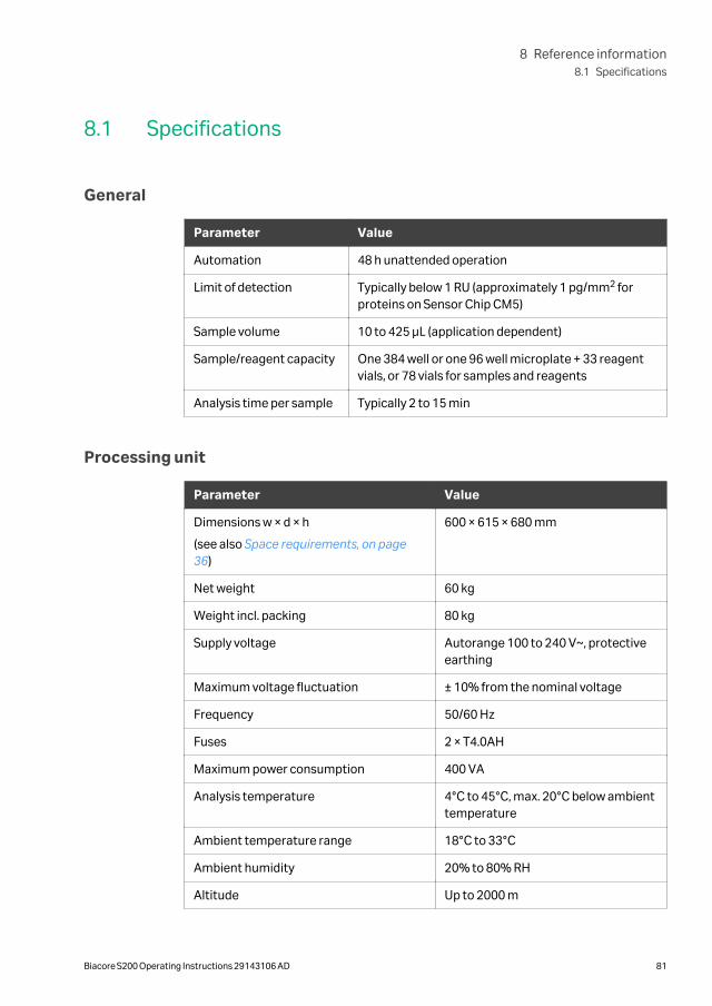
8.1 Specifications
General
Parameter Value
Automation 48 h unattended operation
Limit of detection Typically below 1 RU (approximately 1 pg/mm2 forproteins on Sensor Chip CM5)
Sample volume 10 to 425 µL (application dependent)
Sample/reagent capacity One 384 well or one 96 well microplate + 33 reagentvials, or 78 vials for samples and reagents
Analysis time per sample Typically 2 to 15 min
Processing unit
Parameter Value
Dimensions w × d × h
(see also Space requirements, on page36)
600 × 615 × 680 mm
Net weight 60 kg
Weight incl. packing 80 kg
Supply voltage Autorange 100 to 240 V~, protectiveearthing
Maximum voltage fluctuation ± 10% from the nominal voltage
Frequency 50/60 Hz
Fuses 2 × T4.0AH
Maximum power consumption 400 VA
Analysis temperature 4°C to 45°C, max. 20°C below ambienttemperature
Ambient temperature range 18°C to 33°C
Ambient humidity 20% to 80% RH
Altitude Up to 2000 m
8 Reference information8.1 Specifications
Biacore S200 Operating Instructions 29143106 AD 81
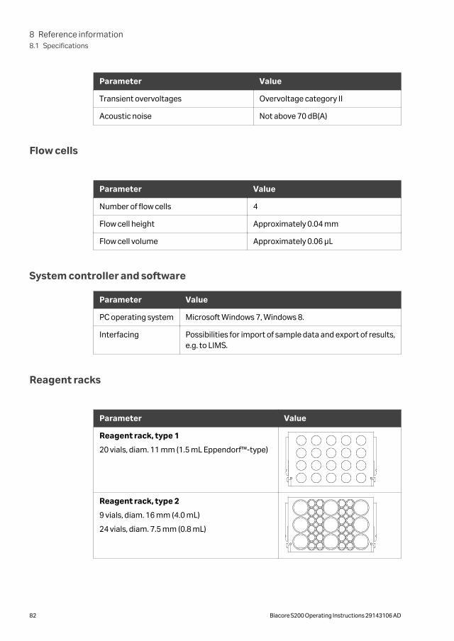
Parameter Value
Transient overvoltages Overvoltage category II
Acoustic noise Not above 70 dB(A)
Flow cells
Parameter Value
Number of flow cells 4
Flow cell height Approximately 0.04 mm
Flow cell volume Approximately 0.06 µL
System controller and software
Parameter Value
PC operating system Microsoft Windows 7, Windows 8.
Interfacing Possibilities for import of sample data and export of results,e.g. to LIMS.
Reagent racks
Parameter Value
Reagent rack, type 1
20 vials, diam. 11 mm (1.5 mL Eppendorf™-type)
Reagent rack, type 2
9 vials, diam. 16 mm (4.0 mL)
24 vials, diam. 7.5 mm (0.8 mL)
8 Reference information8.1 Specifications
82 Biacore S200 Operating Instructions 29143106 AD
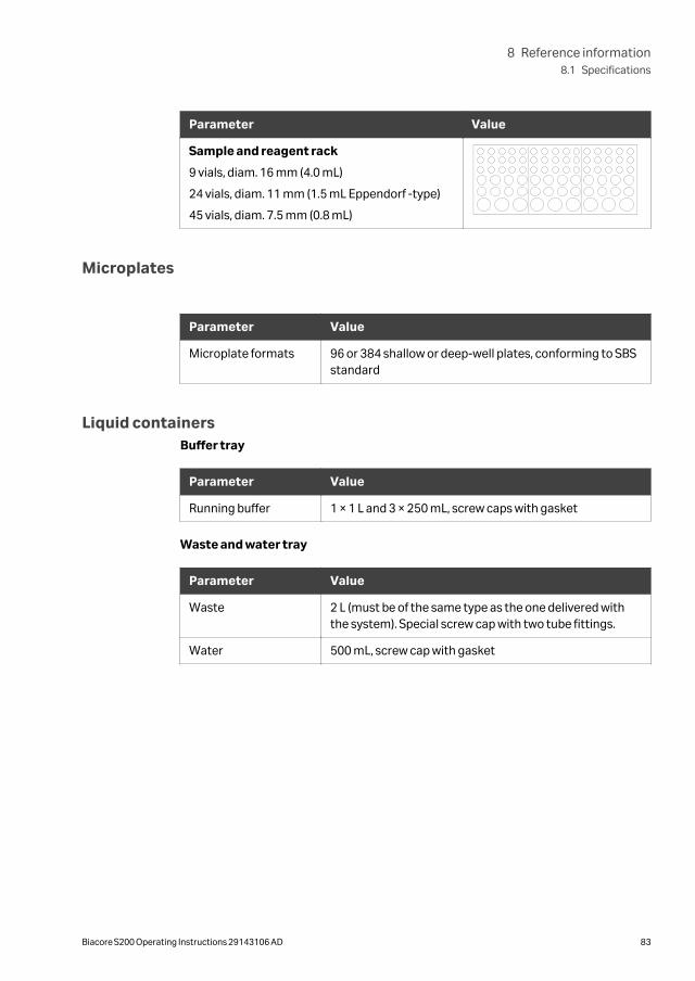
Parameter Value
Sample and reagent rack
9 vials, diam. 16 mm (4.0 mL)
24 vials, diam. 11 mm (1.5 mL Eppendorf -type)
45 vials, diam. 7.5 mm (0.8 mL)
Microplates
Parameter Value
Microplate formats 96 or 384 shallow or deep-well plates, conforming to SBSstandard
Liquid containersBuffer tray
Parameter Value
Running buffer 1 × 1 L and 3 × 250 mL, screw caps with gasket
Waste and water tray
Parameter Value
Waste 2 L (must be of the same type as the one delivered withthe system). Special screw cap with two tube fittings.
Water 500 mL, screw cap with gasket
8 Reference information8.1 Specifications
Biacore S200 Operating Instructions 29143106 AD 83
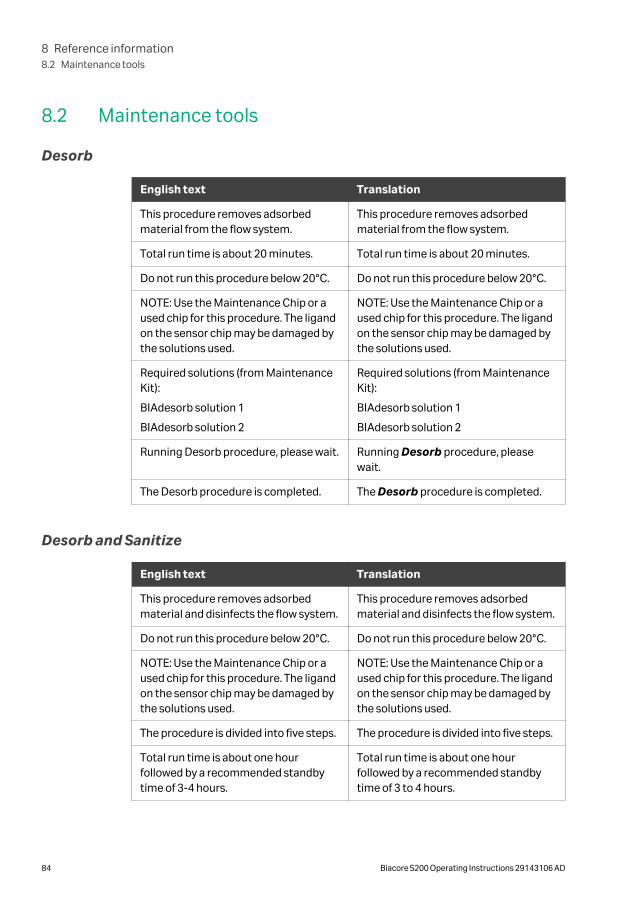
8.2 Maintenance tools
Desorb
English text Translation
This procedure removes adsorbedmaterial from the flow system.
This procedure removes adsorbedmaterial from the flow system.
Total run time is about 20 minutes. Total run time is about 20 minutes.
Do not run this procedure below 20°C. Do not run this procedure below 20°C.
NOTE: Use the Maintenance Chip or aused chip for this procedure. The ligandon the sensor chip may be damaged bythe solutions used.
NOTE: Use the Maintenance Chip or aused chip for this procedure. The ligandon the sensor chip may be damaged bythe solutions used.
Required solutions (from MaintenanceKit):
BIAdesorb solution 1
BIAdesorb solution 2
Required solutions (from MaintenanceKit):
BIAdesorb solution 1
BIAdesorb solution 2
Running Desorb procedure, please wait. Running Desorb procedure, pleasewait.
The Desorb procedure is completed. The Desorb procedure is completed.
Desorb and Sanitize
English text Translation
This procedure removes adsorbedmaterial and disinfects the flow system.
This procedure removes adsorbedmaterial and disinfects the flow system.
Do not run this procedure below 20°C. Do not run this procedure below 20°C.
NOTE: Use the Maintenance Chip or aused chip for this procedure. The ligandon the sensor chip may be damaged bythe solutions used.
NOTE: Use the Maintenance Chip or aused chip for this procedure. The ligandon the sensor chip may be damaged bythe solutions used.
The procedure is divided into five steps. The procedure is divided into five steps.
Total run time is about one hourfollowed by a recommended standbytime of 3-4 hours.
Total run time is about one hourfollowed by a recommended standbytime of 3 to 4 hours.
8 Reference information8.2 Maintenance tools
84 Biacore S200 Operating Instructions 29143106 AD
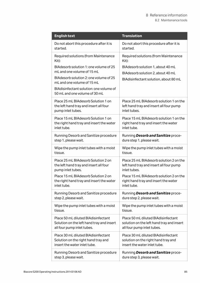
English text Translation
Do not abort this procedure after it isstarted.
Do not abort this procedure after it isstarted.
Required solutions (from MaintenanceKit):
BIAdesorb solution 1: one volume of 25mL and one volume of 15 mL
BIAdesorb solution 2: one volume of 25mL and one volume of 15 mL
BIAdisinfectant solution: one volume of50 mL and one volume of 30 mL
Required solutions (from MaintenanceKit):
BIAdesorb solution 1, about 40 mL
BIAdesorb solution 2, about 40 mL
BIAdisinfectant solution, about 80 mL
Place 25 mL BIAdesorb Solution 1 onthe left hand tray and insert all fourpump inlet tubes.
Place 25 mL BIAdesorb solution 1 on theleft hand tray and insert all four pumpinlet tubes.
Place 15 mL BIAdesorb Solution 1 onthe right hand tray and insert the waterinlet tube.
Place 15 mL BIAdesorb solution 1 on theright hand tray and insert the waterinlet tube.
Running Desorb and Sanitize procedurestep 1, please wait.
Running Desorb and Sanitize proce-dure step 1, please wait.
Wipe the pump inlet tubes with a moisttissue.
Wipe the pump inlet tubes with a moisttissue.
Place 25 mL BIAdesorb Solution 2 onthe left hand tray and insert all fourpump inlet tubes.
Place 15 mL BIAdesorb Solution 2 onthe right hand tray and insert the waterinlet tube.
Place 25 mL BIAdesorb solution 2 on theleft hand tray and insert all four pumpinlet tubes.
Place 15 mL BIAdesorb solution 2 on theright hand tray and insert the waterinlet tube.
Running Desorb and Sanitize procedurestep 2, please wait.
Running Desorb and Sanitize proce-dure step 2, please wait.
Wipe the pump inlet tubes with a moisttissue.
Wipe the pump inlet tubes with a moisttissue.
Place 50 mL diluted BIAdisinfectantSolution on the left hand tray and insertall four pump inlet tubes.
Place 50 mL diluted BIAdisinfectantsolution on the left hand tray and insertall four pump inlet tubes.
Place 30 mL diluted BIAdisinfectantSolution on the right hand tray andinsert the water inlet tube.
Place 30 mL diluted BIAdisinfectantsolution on the right hand tray andinsert the water inlet tube.
Running Desorb and Sanitize procedurestep 3, please wait.
Running Desorb and Sanitize proce-dure step 3, please wait.
8 Reference information8.2 Maintenance tools
Biacore S200 Operating Instructions 29143106 AD 85

English text Translation
Wipe the pump inlet tubes with a moisttissue.
Wipe the pump inlet tubes with a moisttissue.
Place water on the left hand tray andinsert all four pump inlet tubes.
Place water on the left hand tray andinsert all four pump inlet tubes.
Place water on the right hand tray andinsert the water inlet tube.
Place water on the right hand tray andinsert the water inlet tube.
Running Desorb and Sanitize procedurestep 4, please wait.
Running Desorb and Sanitize proce-dure step 4, please wait.
Place tube A in HEPES or TRIS buffer. Place tube A in HEPES or TRIS buffer.
Recommended concentration is 10-50mmol/L.
Recommended concentration is 10 to50 mmol/L.
Let tubes B, C and D hang in the air. Let tubes B, C and D hang in the air.
Running Desorb and Sanitize procedurestep 5, please wait.
Running Desorb and Sanitize proce-dure step 5, please wait.
The Desorb and Sanitize procedure iscompleted.
The Desorb and Sanitize procedure iscompleted.
Allow the system to run in standbymode for at least 3–4 hours beforeperforming a run.
Allow the system to run in standbymode for at least 3 to 4 hours beforeperforming a run.
Empty Buffer Tubing
English text Translation
This procedure empties all four bufferselector inlet tubes. The procedure isdivided into three steps.
This procedure empties all four bufferselector inlet tubes. The procedure isdivided into three steps.
Total run time is about 20 minutes. Total run time is about 20 minutes.
Required solutions:
Deionized water
70% ethanol
Required solutions:
Deionized water
70% ethanol
Place a bottle containing deionizedwater on the left hand plate and insertthe four buffer inlet tubes.
Place a bottle containing deionizedwater on the left hand plate and insertthe four buffer inlet tubes.
This step flushes the buffer selectorwith water.
This step flushes the buffer selectorwith water.
8 Reference information8.2 Maintenance tools
86 Biacore S200 Operating Instructions 29143106 AD

English text Translation
Running Empty Buffer Tubing proce-dure step 1, please wait.
Running Empty Buffer Tubing proce-dure step 1, please wait.
Place a bottle containing at least 10 mL70% ethanol on the left hand plate andinsert the four buffer inlet tubes.
Place a bottle containing at least 10 mL70% ethanol on the left hand plate andinsert the four buffer inlet tubes.
Running Empty Buffer Tubing proce-dure step 2, please wait.
Running Empty Buffer Tubing proce-dure step 2, please wait.
Remove the tubes from the ethanolbottle and allow them to hang in the air.
Remove the tubes from the ethanolbottle and allow them to hang in the air.
This step empties the buffer selector ofliquid.
This step empties the buffer selector ofliquid.
Running Empty Buffer Tubing proce-dure step 3, please wait.
Running Empty Buffer Tubing proce-dure step 3, please wait.
The Empty Buffer Tubing procedure iscompleted.
The Empty Buffer Tubing procedure iscompleted.
Normalize
English text Translation
Normalizes the signal in all flow cells. Normalizes the signal in all flow cells.
Total run time is about 9 minutes. Total run time is about 9 minutes.
NOTE: Do not normalize with the main-tenance chip.
NOTE: Do not normalize with the Main-tenance Chip.
This procedure normalizes the detectorsignal. Total run time is about 9minutes.
This procedure normalizes the detectorsignal. Total run time is about 9minutes.
Required solution (from MaintenanceKit):
BIAnormalizing solution
Required solution (from MaintenanceKit):
BIAnormalizing solution
Normalizing, please wait. Normalizing, please wait.
The Normalize procedure is completed. The Normalize procedure iscompleted.
8 Reference information8.2 Maintenance tools
Biacore S200 Operating Instructions 29143106 AD 87

Wash Buffer Tubing
English text Translation
This procedure cleans buffer tubingfrom adsorbed material, e.g. after usingbuffer with detergent.
This procedure cleans buffer tubingfrom adsorbed material, e.g. after usingbuffer with detergent.
Do not run this procedure below 20°C. Do not run this procedure below 20°C.
NOTE: Use the Maintenance Chip or aused chip for this procedure. The ligandon the sensor chip may be damaged bythe solutions used.
NOTE: Use the Maintenance Chip or aused chip for this procedure. The ligandon the sensor chip may be damaged bythe solutions used.
Select tubes to wash. Select tubes to wash.
This procedure removes adsorbedmaterial from the flow system. Theprocedure is divided into three steps.Total run time is about 30 minutes.
This procedure removes adsorbedmaterial from the flow system. Theprocedure is divided into three steps.Total run time is about 301 minutes.
Do not abort this procedure after it isstarted.
Do not abort this procedure after it isstarted.
Required solutions (from MaintenanceKit):
BIAdesorb solution 1, about 20 mL
BIAdesorb solution 2, about 20 mL
Required solutions (from MaintenanceKit):
BIAdesorb solution 1, about 201 mL
BIAdesorb solution 2, about 201 mL
Place 20 mL BIAdesorb Solution 1 onthe left hand tray and insert tube A.
Place 201 mL BIAdesorb solution 1 onthe left hand tray and insert tube A1.
Wipe the tube with a moist tissue. Wipe the tube with a moist tissue.
Place 20 mL BIAdesorb Solution 2 onthe left hand tray and insert the tube/allfour tubes.
Place 201 mL BIAdesorb solution 2 onthe left hand tray and insert the tube/allfour tubes1.
Place buffer or water on the left handtray and insert the tube/all four tubes.
Place buffer or water on the left handtray and insert the tube/all four tubes1.
NOTE: Remember to put tube A in bufferor water (to be used during standby).
NOTE: Remember to put tube A in bufferor water (to be used during standby).
Running Wash Buffer Tubing procedurestep 1/2/3, please wait.
Running Wash Buffer Tubing proce-dure step 1/2/3, please wait.
The Wash Buffer Tubing procedure iscompleted.
The Wash Buffer Tubing procedure iscompleted.
1 Times, volumes and tube instructions vary acccording to the tubes selected for wash.
8 Reference information8.2 Maintenance tools
88 Biacore S200 Operating Instructions 29143106 AD
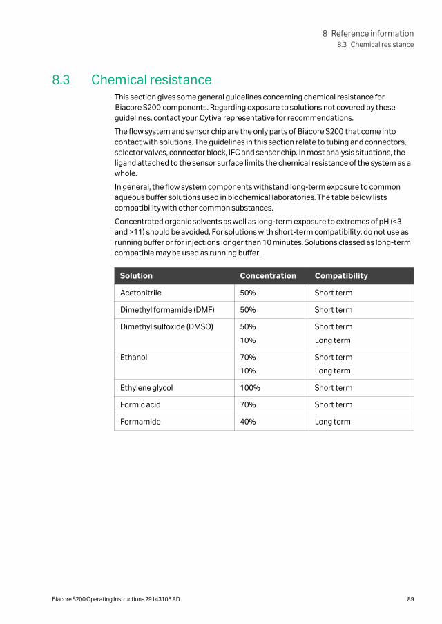
8.3 Chemical resistanceThis section gives some general guidelines concerning chemical resistance forBiacore S200 components. Regarding exposure to solutions not covered by theseguidelines, contact your Cytiva representative for recommendations.
The flow system and sensor chip are the only parts of Biacore S200 that come intocontact with solutions. The guidelines in this section relate to tubing and connectors,selector valves, connector block, IFC and sensor chip. In most analysis situations, theligand attached to the sensor surface limits the chemical resistance of the system as awhole.
In general, the flow system components withstand long-term exposure to commonaqueous buffer solutions used in biochemical laboratories. The table below listscompatibility with other common substances.
Concentrated organic solvents as well as long-term exposure to extremes of pH (<3and >11) should be avoided. For solutions with short-term compatibility, do not use asrunning buffer or for injections longer than 10 minutes. Solutions classed as long-termcompatible may be used as running buffer.
Solution Concentration Compatibility
Acetonitrile 50% Short term
Dimethyl formamide (DMF) 50% Short term
Dimethyl sulfoxide (DMSO) 50%
10%
Short term
Long term
Ethanol 70%
10%
Short term
Long term
Ethylene glycol 100% Short term
Formic acid 70% Short term
Formamide 40% Long term
8 Reference information8.3 Chemical resistance
Biacore S200 Operating Instructions 29143106 AD 89
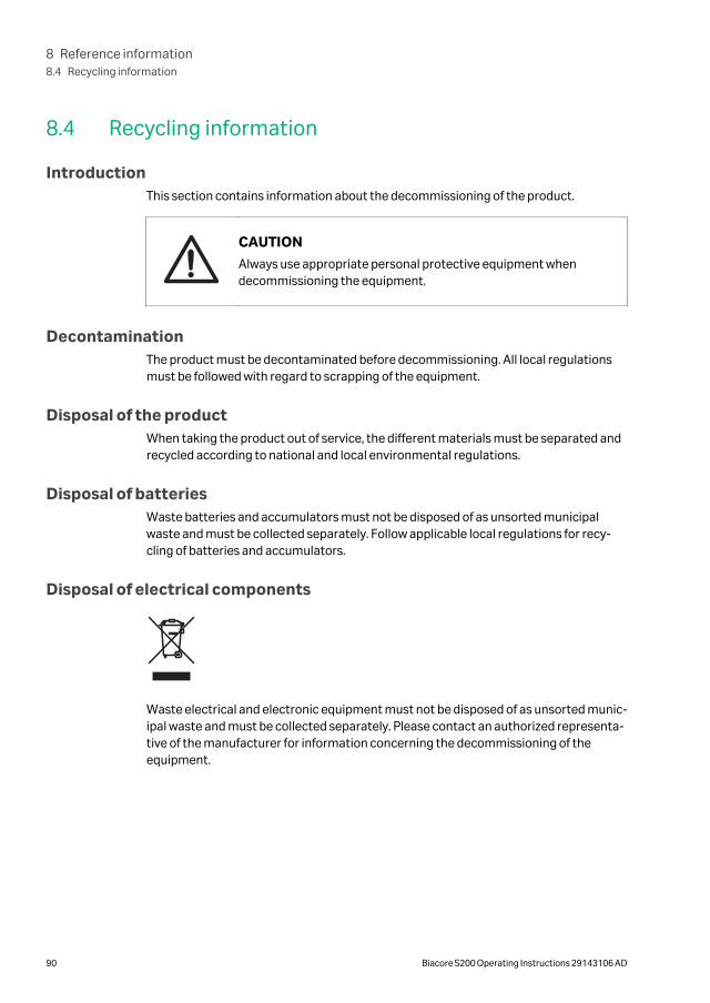
8.4 Recycling information
IntroductionThis section contains information about the decommissioning of the product.
CAUTION
Always use appropriate personal protective equipment whendecommissioning the equipment.
DecontaminationThe product must be decontaminated before decommissioning. All local regulationsmust be followed with regard to scrapping of the equipment.
Disposal of the productWhen taking the product out of service, the different materials must be separated andrecycled according to national and local environmental regulations.
Disposal of batteriesWaste batteries and accumulators must not be disposed of as unsorted municipalwaste and must be collected separately. Follow applicable local regulations for recy-cling of batteries and accumulators.
Disposal of electrical components
Waste electrical and electronic equipment must not be disposed of as unsorted munic-ipal waste and must be collected separately. Please contact an authorized representa-tive of the manufacturer for information concerning the decommissioning of theequipment.
8 Reference information8.4 Recycling information
90 Biacore S200 Operating Instructions 29143106 AD
8.5 Regulatory information
IntroductionThis section lists the regulations and standards that apply to the product.
In this section
Section See page
8.5.1 Contact information 92
8.5.2 European Union and European Economic Area 93
8.5.3 Eurasian Economic UnionЕвразийский экономический союз
94
8.5.4 Regulations for North America 96
8.5.5 Regulatory statements 97
8.5.6 Declaration of Hazardous Substances (DoHS) 98
8.5.7 Other regulations and standards 100
8 Reference information8.5 Regulatory information
Biacore S200 Operating Instructions 29143106 AD 91
8.5.1 Contact information
Contact information for supportTo find local contact information for support and sending troubleshooting reports, visit cytiva.com/contact.
Manufacturing informationThe table below summarizes the required manufacturing information.
Requirement Information
Name and address of manufacturer Cytiva Sweden AB
Björkgatan 30
SE 751 84 Uppsala
Sweden
Telephone number of manufacturer + 46 771 400 600
8 Reference information8.5 Regulatory information
8.5.1 Contact information
92 Biacore S200 Operating Instructions 29143106 AD
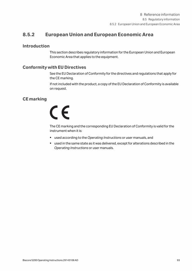
8.5.2 European Union and European Economic Area
IntroductionThis section describes regulatory information for the European Union and EuropeanEconomic Area that applies to the equipment.
Conformity with EU DirectivesSee the EU Declaration of Conformity for the directives and regulations that apply forthe CE marking.
If not included with the product, a copy of the EU Declaration of Conformity is availableon request.
CE marking
The CE marking and the corresponding EU Declaration of Conformity is valid for theinstrument when it is:
• used according to the Operating Instructions or user manuals, and
• used in the same state as it was delivered, except for alterations described in theOperating Instructions or user manuals.
8 Reference information8.5 Regulatory information
8.5.2 European Union and European Economic Area
Biacore S200 Operating Instructions 29143106 AD 93
8.5.3 Eurasian Economic UnionЕвразийский экономический союз
This section describes the information that applies to the product in the EurasianEconomic Union (the Russian Federation, the Republic of Armenia, the Republic ofBelarus, the Republic of Kazakhstan, and the Kyrgyz Republic).
IntroductionThis section provides information in accordance with the requirements of the Tech-nical Regulations of the Customs Union and (or) the Eurasian Economic Union.
ВведениеВ данном разделе приведена информация согласно требованиям Техническихрегламентов Таможенного союза и (или) Евразийского экономического союза.
Manufacturer and importerinformation
The following table provides summary information about the manufacturer andimporter, in accordance with the requirements of the Technical Regulations of theCustoms Union and (or) the Eurasian Economic Union.
Requirement Information
Name, address and telephonenumber of manufacturer
See Manufacturing information
Importer and/or company forobtaining information aboutimporter
LLC Global Life Sciences Solutions Rus
Russian Federation, 123112
Presnenskaya nab., 10, fl. 12, pr. III, room 6
Telephone: + 7 495 739 6931
Fax nr: + 7 495 739 6932
E-mail: [email protected]
Информация о производителе иимпортере
В следующей таблице приводится сводная информация о производителе иимпортере, согласно требованиям Технических регламентов Таможенного союзаи (или) Евразийского экономического союза.
Требование Информация
Наименование, адрес и номертелефона производителя
См. Информацию об изготовлении
8 Reference information8.5 Regulatory information
8.5.3 Eurasian Economic Union
Евразийский экономический союз
94 Biacore S200 Operating Instructions 29143106 AD
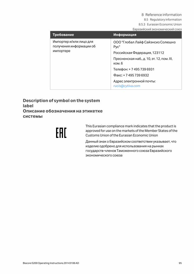
Требование Информация
Импортер и/или лицо дляполучения информации обимпортере
ООО "Глобал Лайф Сайэнсиз СолюшнзРус"
Российская Федерация, 123112
Пресненская наб., д. 10, эт. 12, пом. III,ком. 6
Телефон: + 7 495 739 6931
Факс: + 7 495 739 6932
Адрес электронной почты: [email protected]
Description of symbol on the systemlabelОписание обозначения на этикеткесистемы
This Eurasian compliance mark indicates that the product isapproved for use on the markets of the Member States of theCustoms Union of the Eurasian Economic Union
Данный знак о Евразийском соответствии указывает, чтоизделие одобрено для использования на рынкахгосударств-членов Таможенного союза Евразийскогоэкономического союза
8 Reference information8.5 Regulatory information
8.5.3 Eurasian Economic Union
Евразийский экономический союз
Biacore S200 Operating Instructions 29143106 AD 95
8.5.4 Regulations for North America
IntroductionThis section describes the information that applies to the product in the USA andCanada.
FCC complianceThis device complies with part 15 of the FCC Rules. Operation is subject to the followingtwo conditions: (1) This device may not cause harmful interference, and (2) this devicemust accept any interference received, including interference that may cause unde-sired operation.
Note: The user is cautioned that any changes or modifications not expresslyapproved by Cytiva could void the user’s authority to operate the equip-ment.
This equipment has been tested and found to comply with the limits for a Class A digitaldevice, pursuant to part 15 of the FCC Rules. These limits are designed to providereasonable protection against harmful interference when the equipment is operated ina commercial environment. This equipment generates, uses, and can radiate radiofrequency energy and, if not installed and used in accordance with the instructionmanual, may cause harmful interference to radio communications. Operation of thisequipment in a residential area is likely to cause harmful interference in which case theuser will be required to correct the interference at his own expense.
8 Reference information8.5 Regulatory information
8.5.4 Regulations for North America
96 Biacore S200 Operating Instructions 29143106 AD
8.5.5 Regulatory statements
IntroductionThis section shows regulatory statements that apply to regional requirements.
EMC emission, CISPR 11: Group 1,Class A statement
NOTICE
This equipment is not intended for use in residential environmentsand may not provide adequate protection to radio reception insuch environments.
South KoreaRegulatory information to comply with the Korean technical regulations.
NOTICE
Class A equipment (equipment for business use).
This equipment has been evaluated for its suitability for use in abusiness environment.
When used in a residential environment, there is a concern of radiointerference.
주의A급 기기 (업무용 방송통신 기자재)
이 기기는 업무용환경에서 사용할 목적으로 적합성평가를 받은 기기로서 가정용 환경에서 사용하는 경우 전파간섭의 우려가 있습니다.
8 Reference information8.5 Regulatory information
8.5.5 Regulatory statements
Biacore S200 Operating Instructions 29143106 AD 97

8.5.6 Declaration of Hazardous Substances (DoHS)This section describes the information that applies to the product in China.
根据 SJ/T11364-2014《电子电气产品有害物质限制使用标识要求》特提供如下有关污染控制方面的信息。The following product pollution control information is provided according to SJ/T11364-2014 Marking for Restriction of Hazardous Substances caused by electricaland electronic products.
电子信息产品污染控制标志说明Explanation of Pollution ControlLabel
该标志表明本产品含有超过中国标准 GB/T 26572 《电子电气产品中限用物质的限量要求 》中限量的有害物质。标志中的数字为本产品的环保使用期,表明本产品在正常使用的条件下,有毒有害物质不会发生外泄或突变,用户使用本产品不会对环境造成严重污染或对其人身、财产造成严重损害的期限。单位为年。为保证所申明的环保使用期限,应按产品手册中所规定的环境条件和方法进行正常使用,并严格遵守产品维修手册中规定的定期维修和保养要求。产品中的消耗件和某些零部件可能有其单独的环保使用期限标志,并且其环保使用期限有可能比整个产品本身的环保使用期限短。应到期按产品维修程序更换那些消耗件和零部件,以保证所申明的整个产品的环保使用期限。本产品在使用寿命结束时不可作为普通生活垃圾处理,应被单独收集妥善处理。This symbol indicates the product contains hazardous materials in excess of the limits estab-lished by the Chinese standard GB/T 26572 Requirements of concentration limits for certainrestricted substances in electrical and electronic products. The number in the symbol is the Envi-ronment-friendly Use Period (EFUP), which indicates the period during which the hazardoussubstances contained in electrical and electronic products will not leak or mutate under normaloperating conditions so that the use of such electrical and electronic products will not result inany severe environmental pollution, any bodily injury or damage to any assets. The unit of theperiod is “Year”.
In order to maintain the declared EFUP, the product shall be operated normally according to theinstructions and environmental conditions as defined in the product manual, and periodic main-tenance schedules specified in Product Maintenance Procedures shall be followed strictly.
Consumables or certain parts may have their own label with an EFUP value less than the product.Periodic replacement of those consumables or parts to maintain the declared EFUP shall be donein accordance with the Product Maintenance Procedures.
This product must not be disposed of as unsorted municipal waste, and must be collected sepa-rately and handled properly after decommissioning.
8 Reference information8.5 Regulatory information
8.5.6 Declaration of Hazardous Substances (DoHS)
98 Biacore S200 Operating Instructions 29143106 AD
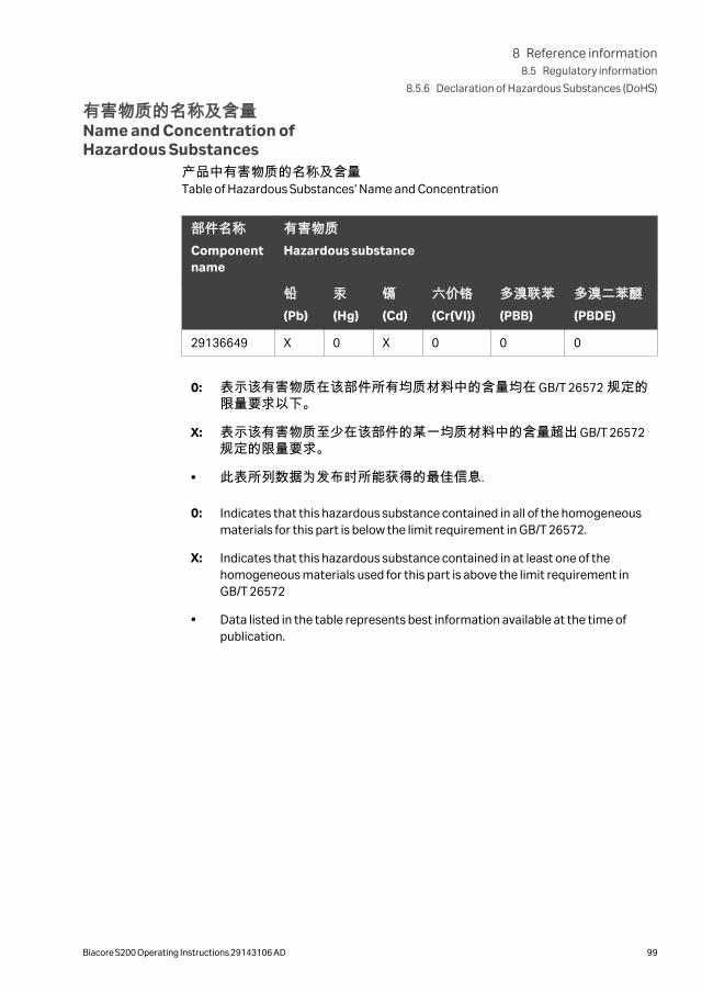
有害物质的名称及含量Name and Concentration ofHazardous Substances
产品中有害物质的名称及含量Table of Hazardous Substances’ Name and Concentration
部件名称Componentname
有害物质Hazardous substance
铅(Pb)
汞(Hg)
镉(Cd)
六价铬(Cr(VI))
多溴联苯(PBB)
多溴二苯醚(PBDE)
29136649 X 0 X 0 0 0
0: 表示该有害物质在该部件所有均质材料中的含量均在 GB/T 26572 规定的限量要求以下。
X: 表示该有害物质至少在该部件的某一均质材料中的含量超出 GB/T 26572规定的限量要求。
• 此表所列数据为发布时所能获得的最佳信息.
0: Indicates that this hazardous substance contained in all of the homogeneousmaterials for this part is below the limit requirement in GB/T 26572.
X: Indicates that this hazardous substance contained in at least one of thehomogeneous materials used for this part is above the limit requirement inGB/T 26572
• Data listed in the table represents best information available at the time ofpublication.
8 Reference information8.5 Regulatory information
8.5.6 Declaration of Hazardous Substances (DoHS)
Biacore S200 Operating Instructions 29143106 AD 99
8.5.7 Other regulations and standards
IntroductionThis section describes the standards that apply to the product.
Regulatory compliance of connectedequipment
Any equipment connected to Biacore S200 should meet the safety requirements ofIEC/EN/UL/CSA 61010-1, IEC/EN/UL/CSA 60950-1, or other relevant national safetyregulations and standards. The equipment should be installed and used according tothe manufacturer's instructions. Within EU, connected equipment must be CE marked.
8 Reference information8.5 Regulatory information
8.5.7 Other regulations and standards
100 Biacore S200 Operating Instructions 29143106 AD
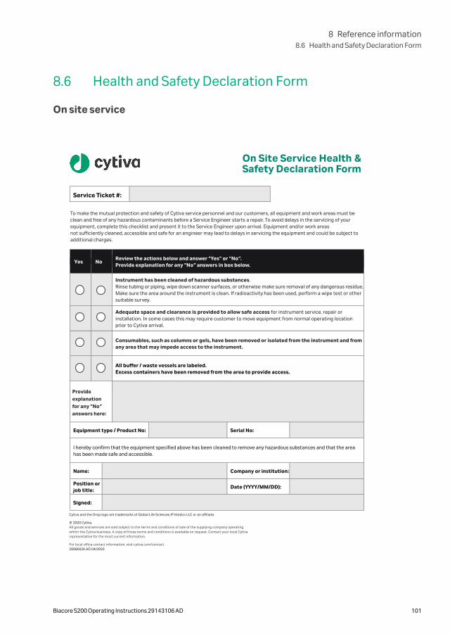
8.6 Health and Safety Declaration Form
On site service
On Site Service Health & Safety Declaration Form
Service Ticket #:
To make the mutual protection and safety of Cytiva service personnel and our customers, all equipment and work areas must be clean and free of any hazardous contaminants before a Service Engineer starts a repair. To avoid delays in the servicing of your equipment, complete this checklist and present it to the Service Engineer upon arrival. Equipment and/or work areas not sufficiently cleaned, accessible and safe for an engineer may lead to delays in servicing the equipment and could be subject to additional charges.
Yes No Review the actions below and answer “Yes” or “No”. Provide explanation for any “No” answers in box below.
Instrument has been cleaned of hazardous substances. Rinse tubing or piping, wipe down scanner surfaces, or otherwise make sure removal of any dangerous residue. Make sure the area around the instrument is clean. If radioactivity has been used, perform a wipe test or other suitable survey.
Adequate space and clearance is provided to allow safe access for instrument service, repair or installation. In some cases this may require customer to move equipment from normal operating location prior to Cytiva arrival.
Consumables, such as columns or gels, have been removed or isolated from the instrument and from any area that may impede access to the instrument .
All buffer / waste vessels are labeled. Excess containers have been removed from the area to provide access.
Provide explanation for any “No” answers here:
Equipment type / Product No: Serial No:
I hereby confirm that the equipment specified above has been cleaned to remove any hazardous substances and that the area has been made safe and accessible.
Name: Company or institution:
Position or job title:
Date (YYYY/MM/DD):
Signed:
Cytiva and the Drop logo are trademarks of Global Life Sciences IP Holdco LLC or an affiliate.
© 2020 Cytiva. All goods and services are sold subject to the terms and conditions of sale of the supplying company operating within the Cytiva business. A copy of those terms and conditions is available on request. Contact your local Cytiva representative for the most current information.
For local office contact information, visit cytiva.com/contact. 28980026 AD 04/2020
8 Reference information8.6 Health and Safety Declaration Form
Biacore S200 Operating Instructions 29143106 AD 101
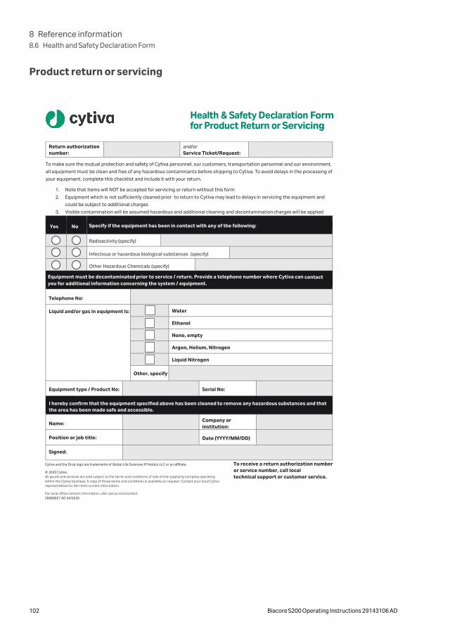
Product return or servicing
Health & Safety Declaration Form for Product Return or Servicing
Return authorization number:
and/or Service Ticket/Request:
To make sure the mutual protection and safety of Cytiva personnel, our customers, transportation personnel and our environment,
all equipment must be clean and free of any hazardous contaminants before shipping to Cytiva. To avoid delays in the processing of
your equipment, complete this checklist and include it with your return.
1. Note that items will NOT be accepted for servicing or return without this form
2. Equipment which is not sufficiently cleaned prior to return to Cytiva may lead to delays in servicing the equipment and
could be subject to additional charges
3. Visible contamination will be assumed hazardous and additional cleaning and decontamination charges will be applied
Yes No Specify if the equipment has been in contact with any of the following:
Radioactivity (specify)
Infectious or hazardous biological substances (specify)
Other Hazardous Chemicals (specify)
Equipment must be decontaminated prior to service / return. Provide a telephone number where Cytiva can contact you for additional information concerning the system / equipment.
Telephone No:
Liquid and/or gas in equipment is: Water
Ethanol
None, empty
Argon, Helium, Nitrogen
Liquid Nitrogen
Other, specify
Equipment type / Product No: Serial No:
I hereby confirm that the equipment specified above has been cleaned to remove any hazardous substances and that the area has been made safe and accessible.
Name: Company or
institution:
Position or job title: Date (YYYY/MM/DD)
Signed:
Cytiva and the Drop logo are trademarks of Global Life Sciences IP Holdco LLC or an affiliate.
© 2020 Cytiva. All goods and services are sold subject to the terms and conditions of sale of the supplying company operating within the Cytiva business. A copy of those terms and conditions is available on request. Contact your local Cytiva representative for the most current information.
For local office contact information, visit cytiva.com/contact. 28980027 AD 04/2020
To receive a return authorization number or service number, call local technical support or customer service.
8 Reference information8.6 Health and Safety Declaration Form
102 Biacore S200 Operating Instructions 29143106 AD
Appendix A
Software tool texts
The on-screen instructions in the maintenance, test and service software tools aregiven in English. Translations to other languages are provided in the local languageversions of these Operating Instructions.
In this chapter
Section See page
A.1 Maintenance tools 104
A.2 Test tools 109
A.3 Service tools 110
A Software tool texts
Biacore S200 Operating Instructions 29143106 AD 103
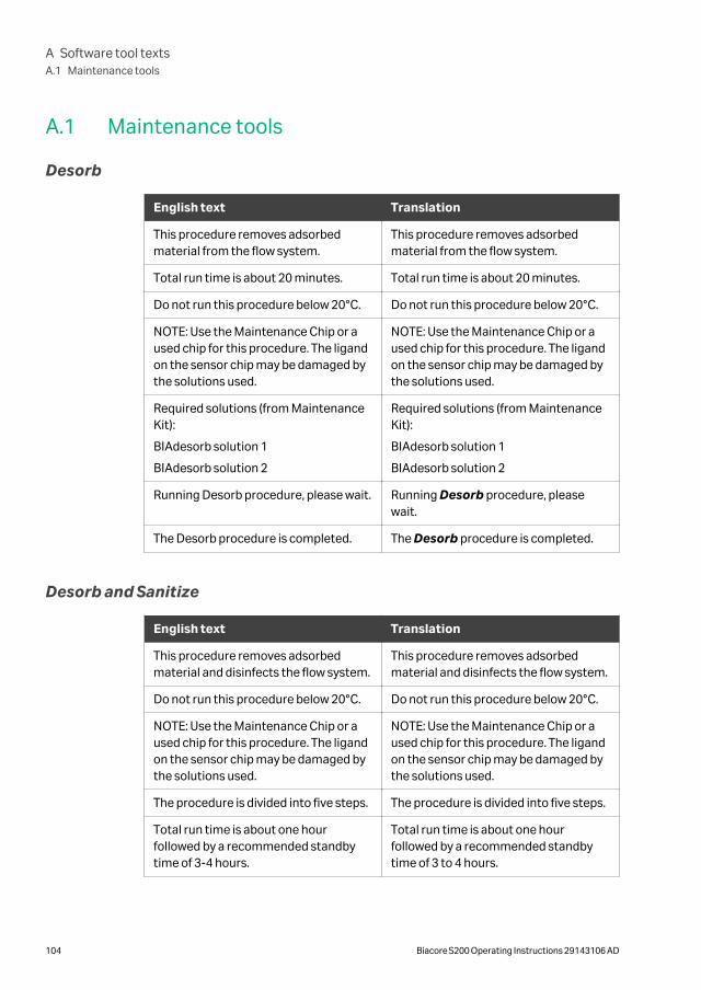
A.1 Maintenance tools
Desorb
English text Translation
This procedure removes adsorbedmaterial from the flow system.
This procedure removes adsorbedmaterial from the flow system.
Total run time is about 20 minutes. Total run time is about 20 minutes.
Do not run this procedure below 20°C. Do not run this procedure below 20°C.
NOTE: Use the Maintenance Chip or aused chip for this procedure. The ligandon the sensor chip may be damaged bythe solutions used.
NOTE: Use the Maintenance Chip or aused chip for this procedure. The ligandon the sensor chip may be damaged bythe solutions used.
Required solutions (from MaintenanceKit):
BIAdesorb solution 1
BIAdesorb solution 2
Required solutions (from MaintenanceKit):
BIAdesorb solution 1
BIAdesorb solution 2
Running Desorb procedure, please wait. Running Desorb procedure, pleasewait.
The Desorb procedure is completed. The Desorb procedure is completed.
Desorb and Sanitize
English text Translation
This procedure removes adsorbedmaterial and disinfects the flow system.
This procedure removes adsorbedmaterial and disinfects the flow system.
Do not run this procedure below 20°C. Do not run this procedure below 20°C.
NOTE: Use the Maintenance Chip or aused chip for this procedure. The ligandon the sensor chip may be damaged bythe solutions used.
NOTE: Use the Maintenance Chip or aused chip for this procedure. The ligandon the sensor chip may be damaged bythe solutions used.
The procedure is divided into five steps. The procedure is divided into five steps.
Total run time is about one hourfollowed by a recommended standbytime of 3-4 hours.
Total run time is about one hourfollowed by a recommended standbytime of 3 to 4 hours.
A Software tool textsA.1 Maintenance tools
104 Biacore S200 Operating Instructions 29143106 AD

English text Translation
Do not abort this procedure after it isstarted.
Do not abort this procedure after it isstarted.
Required solutions (from MaintenanceKit):
BIAdesorb solution 1: one volume of 25mL and one volume of 15 mL
BIAdesorb solution 2: one volume of 25mL and one volume of 15 mL
BIAdisinfectant solution: one volume of50 mL and one volume of 30 mL
Required solutions (from MaintenanceKit):
BIAdesorb solution 1, about 40 mL
BIAdesorb solution 2, about 40 mL
BIAdisinfectant solution, about 80 mL
Place 25 mL BIAdesorb Solution 1 onthe left hand tray and insert all fourpump inlet tubes.
Place 25 mL BIAdesorb solution 1 on theleft hand tray and insert all four pumpinlet tubes.
Place 15 mL BIAdesorb Solution 1 onthe right hand tray and insert the waterinlet tube.
Place 15 mL BIAdesorb solution 1 on theright hand tray and insert the waterinlet tube.
Running Desorb and Sanitize procedurestep 1, please wait.
Running Desorb and Sanitize proce-dure step 1, please wait.
Wipe the pump inlet tubes with a moisttissue.
Wipe the pump inlet tubes with a moisttissue.
Place 25 mL BIAdesorb Solution 2 onthe left hand tray and insert all fourpump inlet tubes.
Place 15 mL BIAdesorb Solution 2 onthe right hand tray and insert the waterinlet tube.
Place 25 mL BIAdesorb solution 2 on theleft hand tray and insert all four pumpinlet tubes.
Place 15 mL BIAdesorb solution 2 on theright hand tray and insert the waterinlet tube.
Running Desorb and Sanitize procedurestep 2, please wait.
Running Desorb and Sanitize proce-dure step 2, please wait.
Wipe the pump inlet tubes with a moisttissue.
Wipe the pump inlet tubes with a moisttissue.
Place 50 mL diluted BIAdisinfectantSolution on the left hand tray and insertall four pump inlet tubes.
Place 50 mL diluted BIAdisinfectantsolution on the left hand tray and insertall four pump inlet tubes.
Place 30 mL diluted BIAdisinfectantSolution on the right hand tray andinsert the water inlet tube.
Place 30 mL diluted BIAdisinfectantsolution on the right hand tray andinsert the water inlet tube.
Running Desorb and Sanitize procedurestep 3, please wait.
Running Desorb and Sanitize proce-dure step 3, please wait.
A Software tool textsA.1 Maintenance tools
Biacore S200 Operating Instructions 29143106 AD 105
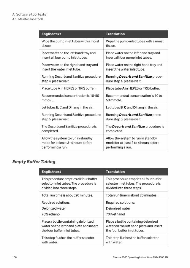
English text Translation
Wipe the pump inlet tubes with a moisttissue.
Wipe the pump inlet tubes with a moisttissue.
Place water on the left hand tray andinsert all four pump inlet tubes.
Place water on the left hand tray andinsert all four pump inlet tubes.
Place water on the right hand tray andinsert the water inlet tube.
Place water on the right hand tray andinsert the water inlet tube.
Running Desorb and Sanitize procedurestep 4, please wait.
Running Desorb and Sanitize proce-dure step 4, please wait.
Place tube A in HEPES or TRIS buffer. Place tube A in HEPES or TRIS buffer.
Recommended concentration is 10-50mmol/L.
Recommended concentration is 10 to50 mmol/L.
Let tubes B, C and D hang in the air. Let tubes B, C and D hang in the air.
Running Desorb and Sanitize procedurestep 5, please wait.
Running Desorb and Sanitize proce-dure step 5, please wait.
The Desorb and Sanitize procedure iscompleted.
The Desorb and Sanitize procedure iscompleted.
Allow the system to run in standbymode for at least 3–4 hours beforeperforming a run.
Allow the system to run in standbymode for at least 3 to 4 hours beforeperforming a run.
Empty Buffer Tubing
English text Translation
This procedure empties all four bufferselector inlet tubes. The procedure isdivided into three steps.
This procedure empties all four bufferselector inlet tubes. The procedure isdivided into three steps.
Total run time is about 20 minutes. Total run time is about 20 minutes.
Required solutions:
Deionized water
70% ethanol
Required solutions:
Deionized water
70% ethanol
Place a bottle containing deionizedwater on the left hand plate and insertthe four buffer inlet tubes.
Place a bottle containing deionizedwater on the left hand plate and insertthe four buffer inlet tubes.
This step flushes the buffer selectorwith water.
This step flushes the buffer selectorwith water.
A Software tool textsA.1 Maintenance tools
106 Biacore S200 Operating Instructions 29143106 AD
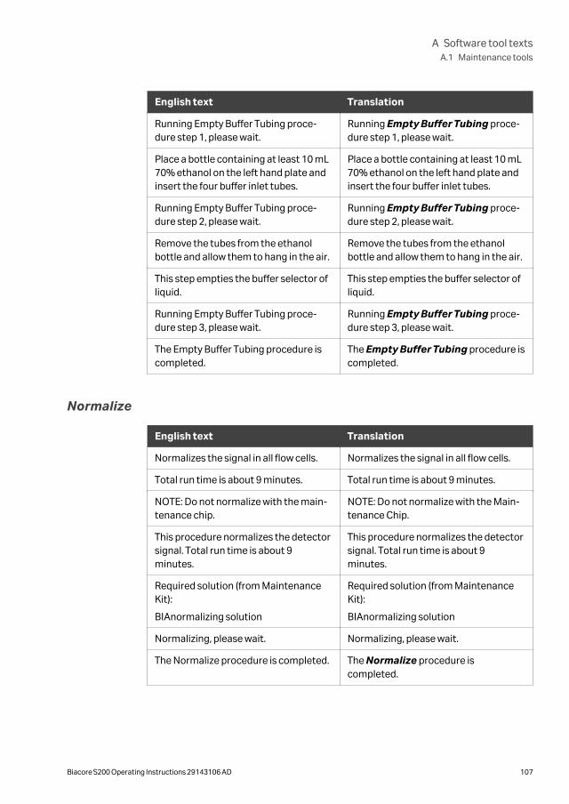
English text Translation
Running Empty Buffer Tubing proce-dure step 1, please wait.
Running Empty Buffer Tubing proce-dure step 1, please wait.
Place a bottle containing at least 10 mL70% ethanol on the left hand plate andinsert the four buffer inlet tubes.
Place a bottle containing at least 10 mL70% ethanol on the left hand plate andinsert the four buffer inlet tubes.
Running Empty Buffer Tubing proce-dure step 2, please wait.
Running Empty Buffer Tubing proce-dure step 2, please wait.
Remove the tubes from the ethanolbottle and allow them to hang in the air.
Remove the tubes from the ethanolbottle and allow them to hang in the air.
This step empties the buffer selector ofliquid.
This step empties the buffer selector ofliquid.
Running Empty Buffer Tubing proce-dure step 3, please wait.
Running Empty Buffer Tubing proce-dure step 3, please wait.
The Empty Buffer Tubing procedure iscompleted.
The Empty Buffer Tubing procedure iscompleted.
Normalize
English text Translation
Normalizes the signal in all flow cells. Normalizes the signal in all flow cells.
Total run time is about 9 minutes. Total run time is about 9 minutes.
NOTE: Do not normalize with the main-tenance chip.
NOTE: Do not normalize with the Main-tenance Chip.
This procedure normalizes the detectorsignal. Total run time is about 9minutes.
This procedure normalizes the detectorsignal. Total run time is about 9minutes.
Required solution (from MaintenanceKit):
BIAnormalizing solution
Required solution (from MaintenanceKit):
BIAnormalizing solution
Normalizing, please wait. Normalizing, please wait.
The Normalize procedure is completed. The Normalize procedure iscompleted.
A Software tool textsA.1 Maintenance tools
Biacore S200 Operating Instructions 29143106 AD 107
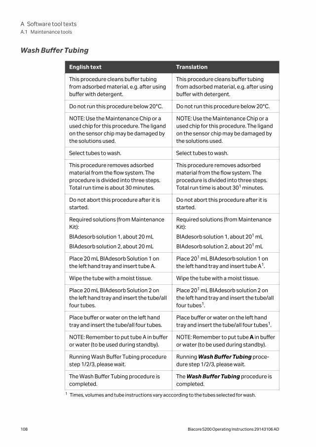
Wash Buffer Tubing
English text Translation
This procedure cleans buffer tubingfrom adsorbed material, e.g. after usingbuffer with detergent.
This procedure cleans buffer tubingfrom adsorbed material, e.g. after usingbuffer with detergent.
Do not run this procedure below 20°C. Do not run this procedure below 20°C.
NOTE: Use the Maintenance Chip or aused chip for this procedure. The ligandon the sensor chip may be damaged bythe solutions used.
NOTE: Use the Maintenance Chip or aused chip for this procedure. The ligandon the sensor chip may be damaged bythe solutions used.
Select tubes to wash. Select tubes to wash.
This procedure removes adsorbedmaterial from the flow system. Theprocedure is divided into three steps.Total run time is about 30 minutes.
This procedure removes adsorbedmaterial from the flow system. Theprocedure is divided into three steps.Total run time is about 301 minutes.
Do not abort this procedure after it isstarted.
Do not abort this procedure after it isstarted.
Required solutions (from MaintenanceKit):
BIAdesorb solution 1, about 20 mL
BIAdesorb solution 2, about 20 mL
Required solutions (from MaintenanceKit):
BIAdesorb solution 1, about 201 mL
BIAdesorb solution 2, about 201 mL
Place 20 mL BIAdesorb Solution 1 onthe left hand tray and insert tube A.
Place 201 mL BIAdesorb solution 1 onthe left hand tray and insert tube A1.
Wipe the tube with a moist tissue. Wipe the tube with a moist tissue.
Place 20 mL BIAdesorb Solution 2 onthe left hand tray and insert the tube/allfour tubes.
Place 201 mL BIAdesorb solution 2 onthe left hand tray and insert the tube/allfour tubes1.
Place buffer or water on the left handtray and insert the tube/all four tubes.
Place buffer or water on the left handtray and insert the tube/all four tubes1.
NOTE: Remember to put tube A in bufferor water (to be used during standby).
NOTE: Remember to put tube A in bufferor water (to be used during standby).
Running Wash Buffer Tubing procedurestep 1/2/3, please wait.
Running Wash Buffer Tubing proce-dure step 1/2/3, please wait.
The Wash Buffer Tubing procedure iscompleted.
The Wash Buffer Tubing procedure iscompleted.
1 Times, volumes and tube instructions vary acccording to the tubes selected for wash.
A Software tool textsA.1 Maintenance tools
108 Biacore S200 Operating Instructions 29143106 AD
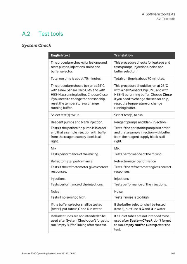
A.2 Test tools
System Check
English text Translation
This procedure checks for leakage andtests pumps, injections, noise andbuffer selector.
This procedure checks for leakage andtests pumps, injections, noise andbuffer selector.
Total run time is about 70 minutes. Total run time is about 70 minutes.
This procedure should be run at 25°Cwith a new Sensor Chip CM5 and withHBS-N as running buffer. Choose Closeif you need to change the sensor chip,reset the temperature or changerunning buffer.
This procedure should be run at 25°Cwith a new Sensor Chip CM5 and withHBS-N as running buffer. Choose Closeif you need to change the sensor chip,reset the temperature or changerunning buffer.
Select test(s) to run. Select test(s) to run.
Reagent pumps and blank injection.
Tests if the peristaltic pump is in orderand that a sample injection with bufferfrom the reagent supply block is allright.
Reagent pumps and blank injection.
Tests if the peristaltic pump is in orderand that a sample injection with bufferfrom the reagent supply block is allright.
Mix
Tests performance of the mixing.
Mix
Tests performance of the mixing.
Refractometer performance
Tests if the refractometer gives correctresponses.
Refractometer performance
Tests if the refractometer gives correctresponses.
Injections
Tests performance of the injections.
Injections
Tests performance of the injections.
Noise
Tests if noise is too high.
Noise
Tests if noise is too high.
If the buffer selector shall be tested(test F), put tube B,C and D in water.
If the buffer selector shall be tested(test F), put tube B,C and D in water.
If all inlet tubes are not intended to beused after System Check, don't forget torun Empty Buffer Tubing after the test.
If all inlet tubes are not intended to beused after System Check, don't forgetto run Empty Buffer Tubing after thetest.
A Software tool textsA.2 Test tools
Biacore S200 Operating Instructions 29143106 AD 109
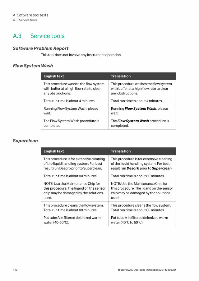
A.3 Service tools
Software Problem ReportThis tool does not involve any instrument operation.
Flow System Wash
English text Translation
This procedure washes the flow systemwith buffer at a high flow rate to clearany obstructions.
This procedure washes the flow systemwith buffer at a high flow rate to clearany obstructions.
Total run time is about 4 minutes. Total run time is about 4 minutes.
Running Flow System Wash, pleasewait.
Running Flow System Wash, pleasewait.
The Flow System Wash procedure iscompleted.
The Flow System Wash procedure iscompleted.
Superclean
English text Translation
This procedure is for extensive cleaningof the liquid handling system. For bestresult run Desorb prior to Superclean.
This procedure is for extensive cleaningof the liquid handling system. For bestresult run Desorb prior to Superclean.
Total run time is about 80 minutes. Total run time is about 80 minutes.
NOTE: Use the Maintenance Chip forthis procedure. The ligand on the sensorchip may be damaged by the solutionsused.
NOTE: Use the Maintenance Chip forthis procedure. The ligand on the sensorchip may be damaged by the solutionsused.
This procedure cleans the flow system.Total run time is about 80 minutes.
This procedure cleans the flow system.Total run time is about 80 minutes.
Put tube A in filtered deionized warmwater (40-50°C).
Put tube A in filtered deionized warmwater (40°C to 50°C).
A Software tool textsA.3 Service tools
110 Biacore S200 Operating Instructions 29143106 AD
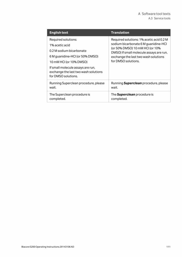
English text Translation
Required solutions:
1% acetic acid
0.2 M sodium bicarbonate
6 M guanidine-HCl (or 50% DMSO)
10 mM HCl (or 10% DMSO)
If small molecule assays are run,exchange the last two wash solutionsfor DMSO solutions.
Required solutions: 1% acetic acid 0.2 Msodium bicarbonate 6 M guanidine-HCl(or 50% DMSO) 10 mM HCl (or 10%DMSO) If small molecule assays are run,exchange the last two wash solutionsfor DMSO solutions.
Running Superclean procedure, pleasewait.
Running Superclean procedure, pleasewait.
The Superclean procedure iscompleted.
The Superclean procedure iscompleted.
A Software tool textsA.3 Service tools
Biacore S200 Operating Instructions 29143106 AD 111
Appendix B
Technical description
About this appendixThis appendix gives a brief description of technical aspects of Biacore S200.
In this chapter
Section See page
B.1 Detection principle 113
B.2 Buffer and sample handling 115
B Technical description
112 Biacore S200 Operating Instructions 29143106 AD
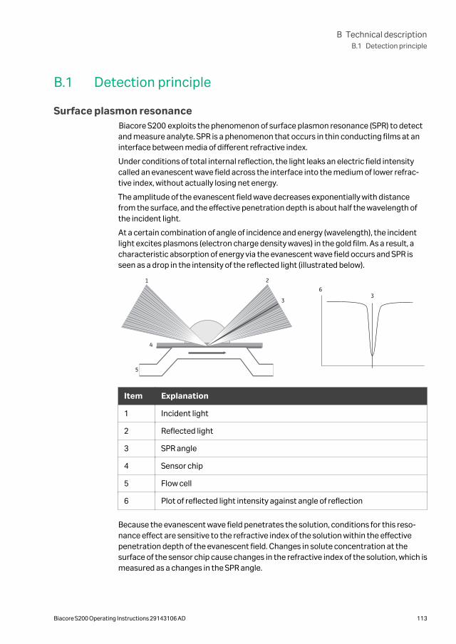
B.1 Detection principle
Surface plasmon resonanceBiacore S200 exploits the phenomenon of surface plasmon resonance (SPR) to detectand measure analyte. SPR is a phenomenon that occurs in thin conducting films at aninterface between media of different refractive index.
Under conditions of total internal reflection, the light leaks an electric field intensitycalled an evanescent wave field across the interface into the medium of lower refrac-tive index, without actually losing net energy.
The amplitude of the evanescent field wave decreases exponentially with distancefrom the surface, and the effective penetration depth is about half the wavelength ofthe incident light.
At a certain combination of angle of incidence and energy (wavelength), the incidentlight excites plasmons (electron charge density waves) in the gold film. As a result, acharacteristic absorption of energy via the evanescent wave field occurs and SPR isseen as a drop in the intensity of the reflected light (illustrated below).
1 2
3
4
5
63
Item Explanation
1 Incident light
2 Reflected light
3 SPR angle
4 Sensor chip
5 Flow cell
6 Plot of reflected light intensity against angle of reflection
Because the evanescent wave field penetrates the solution, conditions for this reso-nance effect are sensitive to the refractive index of the solution within the effectivepenetration depth of the evanescent field. Changes in solute concentration at thesurface of the sensor chip cause changes in the refractive index of the solution, which ismeasured as a changes in the SPR angle.
B Technical descriptionB.1 Detection principle
Biacore S200 Operating Instructions 29143106 AD 113
Note: The reduced intensity of reflected light is not caused by light absorption inthe sample in the conventional (transmission spectroscopy) sense. The lightused to generate the signal is totally internally reflected inside the opticalunit, and it is the evanescent wave that penetrates the sample. Conse-quently, measurements can be made on turbid or even opaque solutions,without interference from conventional light absorption or scattering by thesample.
What SPR measuresIn the configuration used in Biacore S200, the SPR response is a measure of the refrac-tive index of the solution within the penetration distance of the evanescent field wave.This distance (about 300 nm) is small in relation to the height of the flow cell, so thatSPR effectively measures the refractive index at the surface of the sensor chip.
The refractive index of the solution varies with the solute content. When the detectingmolecule is attached to the sensor chip or when analyte binds to the detecting mole-cule, the solute concentration at the sensor chip surface increases, leading to a changein the SPR signal.
The response measured in Biacore S200 is related to the mass of analyte bound and islargely independent of the nature of the analyte. Refractive index contributions fordifferent solutes are additive, so that the amount of detecting molecule attached andthe amount of analyte bound can both be measured with the same detection principle.
B Technical descriptionB.1 Detection principle
114 Biacore S200 Operating Instructions 29143106 AD
B.2 Buffer and sample handling
Flow systemTwo high performance syringe pumps and one peristaltic pump handle the distributionof buffer and water to the IFC and the liquid supply block.
One syringe pump maintains a low flow of buffer through the IFC. The second syringepump is used for aspiration of samples and reagents, and precision delivery to thesensor chip surface via the IFC. The system switches automatically between thesepumps as required.
The peristaltic pump continuously supplies buffer and water to the liquid supply block.The buffer supplied to the liquid supply block is used for washing the injection needle.The buffer flow also helps keeping the liquid supply block clear of precipitated buffer.
Water supplied to the liquid supply block is used for rinsing the needle and the liquidsupply block itself.
Effluent from the IFC and the liquid supply block is conveyed to the waste bottle.
The flow system is illustrated schematically below.
B Technical descriptionB.2 Buffer and sample handling
Biacore S200 Operating Instructions 29143106 AD 115
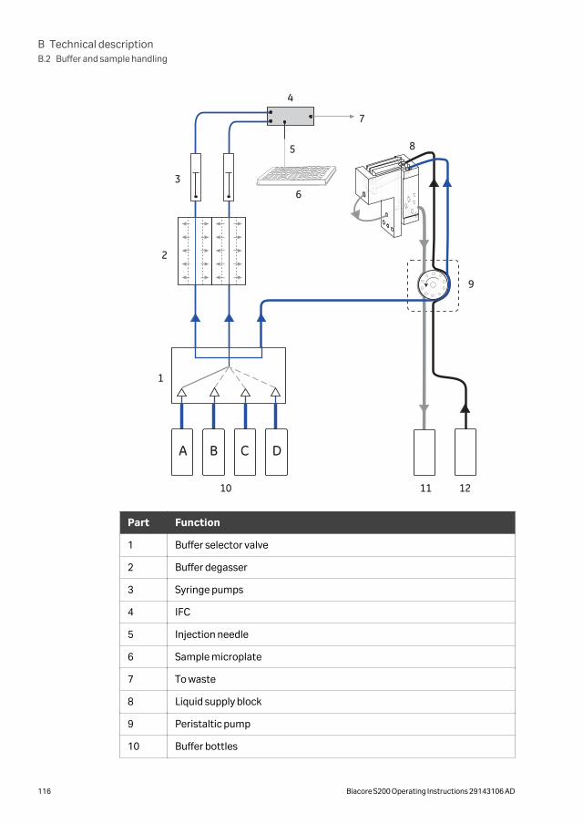
A DCB
1
2
3
4
5
6
7
8
9
10 11 12
Part Function
1 Buffer selector valve
2 Buffer degasser
3 Syringe pumps
4 IFC
5 Injection needle
6 Sample microplate
7 To waste
8 Liquid supply block
9 Peristaltic pump
10 Buffer bottles
B Technical descriptionB.2 Buffer and sample handling
116 Biacore S200 Operating Instructions 29143106 AD
Part Function
11 Waste bottle
12 Water bottle
Buffer degasserThe degasser consists of independent vacuum chambers, each containing membranetubing, which is permeable to small gas molecules.
Each of the two buffer tubes from the selector valve is connected to a separate vacuumchamber. A vacuum pump maintains a low pressure in the vacuum chambers, therebydrawing gas molecules through the membrane tubing.
Valves in the degasser switch pump input between the vacuum chambers and atmos-phere. This keeps the pump clean and increases the service life of the degasser. Anactive carbon filter provides added protection for the vacuum pump.
Cooling unitA maintenance-free cooling unit based on Peltier elements is located behind thesample compartment. Contact your Cytiva service representative if the samplecompartment warms up in spite of a low temperature setting.
B Technical descriptionB.2 Buffer and sample handling
Biacore S200 Operating Instructions 29143106 AD 117
Index
A
Adjust rack tray, 51Ambient environment, 38Autosampler, 24
B
BIAdesorb solution, 61BIAdisinfectant solution, 61BIAmaintenance Kit, 61BIAnormalizing solution, 61BIAtest solution, 61Buffer selector valve, 22Buffer tray, 21Buffers, 45
C
CE, 93conformity, 93marking, 93
Change reagent rack, 54Checking for leaks, 63Chemical resistance, 89Cleaning the instrument, 62Cleaning the sample compart-ment, 69Computer connection, 40Connected equipment, 100
D
Degasser, 22
E
Eject rack tray, 49Emergency procedures, 17
power failure, 17Environmental conditions, 38
F
FCC compliance, 96Finish a run, 56Flow cells, 82
G
General precautions, 10
I
IFC, 32Important user information, 6Install rack tray, 55Instrument overview, 20Integrated µ-Fluidic Cartridge, 32Intended use, 6
L
Leaks, 63Liquid handling system, 31Liquid supply block, 25Liquid system setup, 47
M
Mains power connection, 40Maintenance Kit, 61Maintenance summary, 60Manufacturing information, 92Microplates, 29, 83
N
Normalizing the detector, 64Notes and tips, 7
O
On site service, 101Open sample compartment, 68
P
Peristaltic pump, 23Personal protection, 11Power requirements, 38Power switch, 27Preparing reagents, 53Preparing samples, 52Prerequisites, 6Product return or servicing, 102
Index
118 Biacore S200 Operating Instructions 29143106 AD
Purpose of this manual, 5
R
Rack tray, 29, 49, 51, 55adjusting, 51ejecting, 49installing, 55
Reagent preparation, 53Reagent rack, 29Reagent racks, 82Recycling information, 90
decontamination, 90disposal of electrical compo-nents, 90
Regulatory information, 91Replacing fuses, 74
S
Safety notices, 6Safety precautions, 10
introduction, 10Sample and reagent rack, 30Sample compartment, 24, 68, 69
cleaning, 69opening, 68
Sample preparation, 52Sensor chip, 32, 45
inserting, 45Sensor Chip Maintenance, 61Sensor chip port, 26Set temperature, 48Shutdown, 72Space requirements, 36Specifications, 81Standby, 56, 72Start a run, 56Start the system, 44Status indicators, 27Storage conditions, 73Syringe pumps, 21System check, 66System startup, 44
T
Temperature control, 33Troubleshooting, 76Typographical conventions, 5
W
Wash buffer tubing, 56Waste and water tray, 21
Index
Biacore S200 Operating Instructions 29143106 AD 119

cytiva.com/biacore
Cytiva and the Drop logo are trademarks of Global Life Sciences IP Holdco LLC or an affiliate.
Biacore is a trademark of Global Life Sciences Solutions USA LLC or an affiliate doing business as Cytiva.
Eppendorf is a trademark of Eppendorf AG. Microsoft and Windows are registered trademarks of Microsoft Corporation.
All other third-party trademarks are the property of their respective owners.
© 2020 Cytiva
All goods and services are sold subject to the terms and conditions of sale of the supplying company operating within the Cytivabusiness. A copy of those terms and conditions is available on request. Contact your local Cytiva representative for the most currentinformation.
For local office contact information, visit cytiva.com/contact
29143106 AD V:6 09/2020