Embed Size (px)
Citation preview
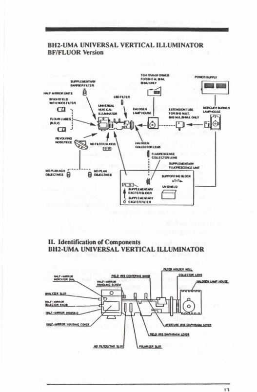
BH2-UMAUniversal VerticalIDuminator
InstructionManual
OLYMPUS CORPORATION
TABLE OF CONTENTS
PAGEPrerace 5Precautions SI. Standard Configurations 6-13
A Univeml (BF/DFII'OLlfLUORJDIC) Version 6·7
lIluSb'abon 7
I,l. Brightfield/Darklield/DIC/POL Version 8
Illustration 9
C. Brightfield/Darkfield Version 10
JIIustrabon • II
O. BrightfieldJFluorescence Version 12
Illustration 13
II. IdentifICation ofComponenls 13
Ill. Assembly 14·19
A. General 14·16
1. Mounting the Universal Vcnicalllluminator 14
2. Mounting the VerticalllluminalOr Lamp 14Housing
3. Mounting the Bulb 14-15
A. For the Halogen LampB. For the Mercury Owner
4. Mounting the Bulb Socket 15
A. For the Halogen LampB. For the Mercury Owner
5. Connecting the Vutical Illuminator Bulb 16
Socke.Cord
A. For the Halogen Lamp
B. For the Mercury Burner
2
B. Universal Version (BF/DF/P01.../F1..UOR/Dle) 16-18or BF/DF/DIC/POL Version
I. Inserting the Half-Mirror UnilS 16-17
2. Inserting the Polarizer 17A. For RenecLed Light Nomarski OIC
ObservationB. For Renected Light Simple Polarizing
ObseJ'\lation3. Inserting the Analyzer 17
4. Inserting the Tint Plate 17
5. Mounting the NomarsJc:i Prism Ring Adapters 17
6. Mounting the Nomarski Prism AltaChmenLS 187. Mounting the Objectives 18
8. Mounting the Revolving Nosepiece 18
C. BrighlfieJd/DartJield DC 18-19BrighlfieldlFloorescence Versions
1. Inserting the HaI(·MiJror Uniu 18-19
2. Inserting the NO Filter Slider 19
3. Mounting the Objectives. 19
IV. Oper.uioo 2ll-24
1. Switching the Light Sourte On 20
A. Fer the Halogen LampB. For the Mercury Burner
2. Centering the Light Source 21-22
A. For the Halogen LampB. For the Mercury BurnerC. Without Centering Screen
3. Centering the Fttld Iris Diaphragm 22
4. Adjusting the Fttld Iris Diaphragm 23
A. For Reneclt.d Light BrightfieldObservation
B. For Reflecled Light DarklieldObservatior:
)
S. Adjusting the Aperture Iris Diaphragm 23
A. For Reflected Light BrightfieldObservation
B. For Reflected Light DarkfleldObservation
6. Inserting the Fillers 24V. Observation 25·30
A. Reflected Light Brightfteld/Darkfield Observation 25·26PreparationSummary of Reflected Light BrightlieldJDarkfield
Observation Procedme
B. Reflected Light Nomarski Differential Interference 26-27Contrast
PrepamtionSummary of Reflected Light Nomarski ole
Proced...
C. Reflected Light Simple Polarizing Observatioo 27·28PrepamtionSummary of Reflected Light Simple Polarizing
Proced...
D. Reflected Light Floorcscence Observation 29-30
PreparationSummary of Reflected Light Fluorescence
Observation
4
PREFACE
As l1lis insuuction manual describes the operation aCme BH2·UMAUniversal VerticalllluminatOf attachment OIIly, it is recommended!.hat Lhe user read the insuuclion m..nuals for the miclOscopc beingused as well, in order 10 obtain optimum performance from theintegrated use of these inSlIumenLS.
PRECAUTIONS
Observe lhe Following Points Carefully
I. Always handle this auaehment with as much care as you would amicroscope. Handle it carefully and avoid subjecting it 10 sudden orsevere impact.
2. When replacing the bulb or the fuse, be sure 10 Wlplug the powercord first
3. Do noc. use organic solvents such as xylene. ether, or alcohol 10clean Lhe microscope components. If componenLS are heavily soiLed.wipe wilh a cloch moistened wiLh neuuaJ detergent.
4. To clean the half-mirror units (e. g. rel1ecting surfaces of themirrors), blow wilh a hand blower. If the dust cannOl be removed byblowing, contact Olympus repair sttvice or your authorized localagent
S. Make sure 1hal no dirt, fingerprints. CIC. are left on the bulbsurface. If it is stained, wipe the bulb surface dean wiLh a smallamount or an alcohol-ether mixuue or benzine.
6. While the BH2·UMA and me microscope arc not in usc, be sure10 slOre it under a dust cover, awa), from moistw-c and hwnidit)'.

J. STANDARD CONFIGURATIONS
A. UNIVERSAL (BFIDFIPOIlFLUORlDlC) VERSION
Unil
Universal vertical illuminatorBrighlfield half-mirror unitBrightfield half-mirror unit
with ND05 filterDarkfield half-mirror unitBlue nuorescence half-mirror unitGreen fluorescence half-mirror unitViolet fluocesoence half-mirror unitNO filler sUder, including ND 12 ftJterlint plate. including NO 12 filterPolarizerAnalyzerLight balancing daylight fillerHalogen lamp housing (wilh halogen
coUeclor lens)Halogen bulbTransformer·fluorescence supplementary unit.:
Supplementary exciter sliderAoorescence collector lensSupporting blockUV proIective shield
Extension tube ••Mercury lamp housingMercury lampPower supply unitCentering screenNomarski prism attachment!:
Nomarski5XNomarski tOXNomarski 20XNomarski SOXNomarski tOOX
BH2·UMABH2-UBFBH2-UBFL
BH2-UDFBH2-UOMBBH2·UOMGBH2-UOMVBH2-UNOBH2-lJIl' s3IlBH2-UFOBH2-UAN20LB03-WBH2-ULSHgO
12V SOW HALBH2-TGHBH2-URFBH2-UFFBH2-ULBH2-UABH2-UCCVBH2-UETBH2-LSRFUSH IQZOBH2-RFLBH2-SGRF
U-NICs-NU-NICIO-NU-NIC2O-NU-NICSO-NU-NIClOO-N

Universal objectives:
Nco S Plan 5X NICNco S Plan lOX NICNco S Plan 20X NICNco S Plan SOX NICNco S Plan lOOX NIC
NEOSPL5X-NICNEOSPLlOX-NICNEOSPL20X-NICNEOSPL50X-NICNEOSPLlOOX-NIC
-Required for BHT-M. BHM. BHMJ. only.
"For use wilh We BH2·WLT. BH2·WL, BHMJL.
BH2-UMA UNIVERSAL VERTICAL ILLUMINATORBF/DF/POlJFLOURlDlC Version

8. IIRIGHTFIELDIDARKFlELOIDlCIPOL VERSION
Unit
Uni~ersal vertical illuminatorBrightfield half-minor unitOarkfield half-mirror unitNO filter slider. induding NO 12 filterlint plate, including NO 12 filterPolarizerAnalyzerLight balancing daylight mterHalogen lamp housing(with halogencollector lens)Halogen bulbTransformer·
NomlUSki prism auachments:NomlUSki SXNOmalSki lOXNomarski 20XNomarski SOXNomarski IOOXUniversal objectives:
Neo S Plan 5X NICNeo S Plan lOX NICNeo S Plan 20X NICNeo S Plan 50X NICNeo S Plan IOOX NIC
·RequiIed for OIIT-M. OHM, OHMJ only.
BH2·UMABH2·UBFBH2·UDFBH2·UNDBH2·UTP530BHZ·UPOBHZ·UAN20l.BD)·WBH2·ULSH80
12V 50WHALBHZ·TGH
U·NIC5-NU·NIClo-NU·NIC20-NU·NIC50·NU·NIClOO-N
NEOSPL5X·NICNEOSPLlOX·NICNEOSPL20X·NICNEOSPLSOX-NICNEOSPLIOOX·NIC
8

BII2-UMA UNIVERSAL VERTICAL ILLUMINATORBF/DF/DICIPOL Version
----
=M)fI.1U.IlUll @:!J
,,,lNl ...."[ ,=
.--""~
I-- "-, '_ ...,_... <;;?
I10 NCO'"","_
e ...."IOl.
•

C. IlRIGHTFIELDIDARKFlELD VERSION
Unil
Universal verticaJ ilIumirworBrightlield haJr·mirror unitDarkfield hair-mirror unitNO filter slider. including NO 12 fdte:rlight balancing daylight fLIlerHalogen lamp housing(wilh halogencollector lel13)Halogen bulbTransronner·Objcctives:
Nco S Plan Ach SXNco S Plan Acb lOX· TNco S Plan Ach 20X . TNco S Plan Ach SOX
·Required r(l' BHT·M, BHM, BHMJ only.
BH2·UMABH2·UBFBH2-UOFBH2·UNO20l.B03·WBH2-ULSH80
12V SOW HALBH2·TGH
NEOSPL5XNEOSPLIOX·TNEOSPI.2OX·TNEOSPLSOX
'0

BH2-UMA UNIVERSAL VERTICAL ILLUMINATORO.~IOF Version
,.,_....-~
,..,-....-...---~
----
"
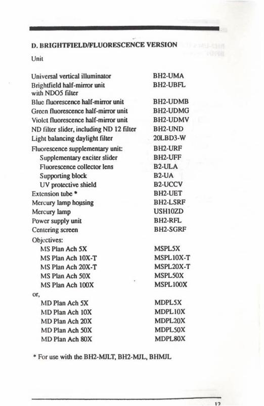
D. DRIGHTFIELDIFLUORESCENCE VERSION
Unit
Universal vertical illuminatorBrighlfield half-mirror unitwith ND05 fl.IltrBluc fluorescence half-mirror unitGrecn fluorescence Ilalf-mirror unitViolet fluorescence haIr-mirror unitNO filler slider, including NO 12 ftlterLight balancing daylight edrer
Ruorescence supplementary unit:Supplementary exciter sliderRuorescence collector lensSupporting blockUV protective shield
Extension tube·Mercury lamp hopsingMercury lampPower supply unitCentering screenObjectives:
MS Plan Ach 5XMS Plan Ach IOX·TMS Plan Ach 20X·TMS Plan Ach 50XMS Plan Ach lOOX
or,MO Plan Ach 5XMO Plan Ach lOXMO Plan Aeh 20XMO Plan Ach 50XMD Plan Ach SOX
BH2·UMABH2·UBFL
BH2·UDMBBH2·UDMGBH2-UDMVBH2-UNO20LBD3-W
BH2·UHFBH2·UFFB2·ULAB2-UAB2-UCCVBH2-UETBH2·LSRFUSHIOZDBH2-RFLBH2·SGRF
MSPLSXMSPLlOX·TMSPL20X·TMSPL50XMSPLlOOX
MDPLSXMDPLIOXMDPL20XMDPL50XMOPL80X
• For use with the BH2-MJLT, BH2-MJL. BHMlL
BH2·UMA UNIVERSAL VERTICAL ILLUMINATOROF/FLUOR Version
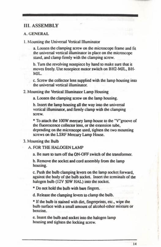
II. Idrnlirte:alion or CompontnlSBH2·UMA UNIVERSAL VERTICAL ILLUMINATOR
•---- ~:::.=- /0 o Q
"'-_00 ;' '( g 18.y....
-
\:•
-"'.,.,.. ..
"
III. ASSEMBLY
A. GENERAL
I. Moonling the Univusal Vc.rticaIIlluminall:w
a. Loosen the clamping screw 00 the microscope frame and fitthe universal vertical illuminator in place on the microscopestand. and clamp firmly with the clamping screw.
b. Tum the revolving nosepiece by hand to make sure thai itmoves freely. Use nosepiece mOlor switch on 8H2-MJI.. 8HMJL.
c. Screw the collector lens supplied wim the lamp housing intothe universal vertical illuminator.
2. Mounting the Vertical U1uminalOr Lamp Housing
a. Loosen the clamping screw on the lamp housing.
b. Insen the lamp housing aU the way inlo the universalvertical iUuminaKJ'. and funlly clamp with the clampingscrew.
• To allach the lOOW mercury lamp house to the ·V·groove ofthe noorescence collector lens. or the Cllccnsion lube.depending on the ffitcroscope used, tighten the two mountingscrews on the LSRF Mercury Lamp House.
3. Mounting the Bulb
A. FOR THE HALOGEN LAMP
a. Be sure 10 tum off tho ON-oFF switch of the transformer.
b. Remove the socket and cord assembly from the lamphousing.
c. Push the bulb clamping levers on the lamp socket ()'Ward,against the body of the bulb socket. Insert the Icnninals or thehalogen bulb (12V SOW HAL) into the socket
• Do not hokllhc bulb with bare fingers.
d. Rekase the clamping leven to clamp the bulb.
• tr the bulb isstained with dirt, fingerprinlS. ele., wipe thebulb surface with a small amount or a1cohol-ether mixture orbenzine.
e. Insert the bulb and sockel into the halogen lamphousing and ughlen the locking SClCW.
14
B. For lhe Mercury Burner
• Always swiu:h of( the power supply unit prior to mercuryburner replat:emenl. Replace lhe burner afu:r about 200working haUlS.
a. Be sure to lurn off the power SlIpply switch.
b. Remove the burner socket assembly from lhe lamp housing.
c. Insert the burner with its lower eleclrOde (marked "+") intome bouom Ienninal and tighten me clamping screws securely.
• Ascenain that no din, fingerprints, etc. are lefl on lhe burnersurface. and when ioslalJing, be careful nO( 10 touch the quarttglass ponion. If the burner is stained, wipe its sUiface cleanwith a small amount of alcohol-ether muture or benzine.
d. Attach lhe conn«:ting wire to lhe top pole of lhe bulb andtighten the locking screws.
e. Insert me burner and socket into the mercury lamp housingand tighten with the locking screw.
• Prior 10 fuse replacement in the power supply Wlil,disconnect the power cord from the AC outJeL
4. Mounting the Bulb Socket
A. For lhe Halogen Lamp
a. Loosen lhe bulb socket clamping screw on lhe bulb socketin advance.
b. Insert me socket. with the locating groove in the lamphousing aligned with me clamping screw.
c. Tighten clamping screw 10 fix bulb socket in place.
B. For lhe Mercury Bwner
a. Insert the socket into the lamp housing by first seuing mehooks at the base of the socket. which acts as a binge. into thelamp house.
b. Tighten the clamping screw at me top of the socket into theside of the lamp bouse to fax the bulb socket in place.
IS
5. Connocting the Universal Illuminator Bulb Socket Cord
A. For the Halogen Lamp
a. Plug in the halogen lamp bulb socket cord inlo theconnoctor on the rear of the microscope stand.
• If a separate transformer is used, plug the lamp bulb socketcord into the t2V 50W transformer and plug the transformercord into the mains.
B. For the Mercury Bumer
a. Plug in the mercury burner socket cord into the connector.on the reM of the mercury power supply uniL.
b. Plug the mercury burner power supply cord into the mains.
B. UNIVERSAL VERSION (BFfDFIPOUFLUORlDlC) ORBF/DF/DlClPOL VERSION
I. Inserting the Half-Mirror Unit
a. Remove the half-mirror housing cover plates on the rightand left sides of the universal illuminator.
• The covers arc kept in place by magnets. Be careful not tolose them.
b. Unscrew the half-mirror unit handling screw from theuniversal iIIwninator housing and screw it into the desiredhalf-mirror uniL
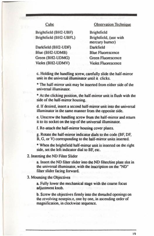
cw.:BrightflCld (BHl·UBF)BrightflCld (BH2·UBFL)
Darkfield (BH2·UDF)
Blue (BH2-UDMB)Green (BHl-UDMG)
V.,lel (BHl-UDMVj
Observation Tecbnique
Brigbtfield, Polarized, DIeBrigbtfield, (usc withmercury burner)DarkfieldBlue FluorescenceGreen FluorescenceViolet Fluorescence
c. Holding the handling screw, carefully slide the half-mirrorunit into the universal illuminator until it clicks.
• The half-minor unit can be inserted from either side of theuniversal illwninator.
• At the clicking IX'sition, the half-mirror unit is nusb with theside of the balf·mirror housing.
"
d. If desired. insert a second half-mirror unit into the universalilluminator in the same manner. from the opposite side.
e. Unscrew the handling screw from the half·mirror and returnit to its socket on the top of the universal illuminator.
f. Re-anach the half-mirror housing cover plates.
g. Rotate the half·mirror indicator dials to the cooe (BF. OF,B, G. or V) corresponding to the half·mirror units insened.
• When the brightfield half-mirror unit is inserted on the rightside. sct the left indicator dial to BF, etc.
2. Inscrting the Polarizer
A. For Reflected Light Nomarski OIC Observation
a. Insert the polarizer slider with the NIC mark facing forward,into the polarizer slot of the universal illuminator, from the leftside, until the polarizer is in the light path.
B. For Reflected Light Simple Polarizing Observation
a. Insen the polarizer slider into the polarizer slot of theuniversal illuminator as above. with the "PO~ mark facingf()(Ward.
3.lnscrting !he Analyzer
a. Inscn the analyzer slider, with the inscription ~ A~ on top,into the analyzer slot on the front of the universal illuminator.
4. Inserting the lint PlaLe
a. Inscn the lint plate slider into the NO filter/tint plate slot ofthe universal illuminator.
• Inserlthe tint plate slider SO as to engage the empty hole inthe light path.
5. Mounting the Nomarski Prism Ring Adapters
a. Loosen the prism clamping screw of the Nomarski prismswith an Allen wrench, and remove the Nomarski ring adaptersfrom the Nomarski prism attachment
b. With the supplied screwdriver. finnly screw theNomarski prism mount~ into the revolving nosepiece.
17

6. Mounting the Nomarsti Prism AuaehmenLS on the DetaehedNosepiece
a. Moum Ihc Nomarsk.i prisms by inscning them over Ihccircular dovewl guides or Ihe Nomatski ring adapcers, one byone in ascending order of magnifICation. in clockwisedirection. and Ihcn tighten the prism damping screws firmlywith Ihe Allen wrench.
• To simplify the mounting or the Nomarski prisms. rullydamp the prisms only afaer aU or Ihe prisms have beenmoonted on the nosepiece.
7. Mounting the Objectives
a. Screw the ob;eeuves fumly into the threads or Ihe Nomarskiprisms. acrording to corresponding magnification power.
8. Mounting lbe Revolving Nosepiece
a. Lower the stage by lUming the coarse rocus adjustmcnlknob.
b. CarefuUy instSt Ihe revolving nosepiece inlD the dovcl3i1guideway or the microscope stand.
c. Push the nosepiece all the way in. and lighten it fannly wilhthe nosepiece clamping screw.
C. BRIGIIT/DARKFIELD/FLUORESCENCE VERSIONS(Bfffif OR BflFLUOR ONLY)
I. Inserting the Half·Mi.m:Jr Unlts
a. Remove Lhe halr·mirror housing cover plates on the rightand left sides or lbe univcrsal iIIwninator.
• The covers are kept in place by magneu. Be carerul not tolose Ihem.
b. Unscrew the half·minu unit handHng screw rrom theuruvusal i1huninalOr and screw it inlo IDe desired half·mirrorunit.
18
Brigh.rocld (BH2-UBF)Brigh.rocld (BH2-UBFLl
Darkrocld (BH2-UOF)Blue (BH2-UOMB)Green (BH2-UOMG)Viole' (BH2-UOMVl
Qbscrvation Technique
8righlfield8righlfield. (use withmercury burner)DarkfieldBlue AUOfCscenceGreen F1uorescenceViolel Auorescence
c. Holding the handling screw. carerully slide the halr-mirrorunit in the universal illuminator until it clicks.
• The hair-mirror unit may be inserted rrom eilhu side or theuniversal illwninawr.
• AI the clicking position, the tlalr·mirror unit is flush with theside or the hair-minor housing.
d. Ir desired. insert a second haIC-minor unit inla the universalilluminator in the same manner rrom the opposilC side.
e. Unscrew the handling screw from the hair-mirror and returnit to its sackelon the lOp or the universal illuminator.
r. Re-auach the halr-mirror housing cover plates.
g. Rotale the half·mirror indicalor dials to the code (OF. OF,8. G. or V) corresponding 10 the hair-minor units insened.
• When the brighlf.ead halr·mirror unit is inserted on the rightside. set the 'ert indicator dial 10 8F, elC.
2_lnscning lhe NO Filler Slider
a. Insert the NO filler slider tRIO the NO fiherNnt plait slol inthe universal illuminator, with the inJCripLion on the ~ND·
filler slider racing rorward.
3. Mounting the Objectives
a. Fully lower the mechanical sc.age with the coarse rocusadjustment knob.
b. Screw the objcclivcslinnly inla the threaded openings onthe revolving nosepi«e, one by one. in ascending order ornuagnirtealion. in clockwise sequence.
I.
IV. OPERATION
I. Switching the Light Source OnA. For lbe Halogen Lamp
a. Set the line vollage sek:ctor switch on the transfonner lOconform with the local mains Yahage.
b. Set the voltagc adjustment knob at the lowest voltageposition. and twn on me ON-QFF switch.
c. Turning the volcage adjustment koob clockwise increasesvoltage and the voItmelU LED lights up. accordingly.
B. For the Men:ury Burner
a. Make sure that the line voltage selector switch on the powersupply unit is set to conform with the kx:a1 mains vahage.(This switch can be turned with a screwdriver. and can be setto the raUowing voltages;lOOV /lIOV /l20V or220V I240V).
b. Set the fn:quency sdoclOl' switeh 10 conform with lhe kJcalmains frequency. (This switeh can be adjusted with ascrewdriver).
c. Ascouin that the connecting cord from the power supplyunit to the lamp socket. and the mains cord are correcLlyconnccled.d. Tum on the main switeh of the power supply unit. Theswiteh will light up green.
• The burner sometimes may not ignite lhe first lime, due tothe electrode condition, etc. Ir your bwner does not ignite.repeat (tuning on the main switch several limes.
• To protect Ihe circuitry of ytU autexnotic photomicrographicauachmenlS, turn them on only aflel the mercury burner hasbeen ignited.
•. 2 or 3 minuleS aflU ignilion. the arc will be stabilized.
• Do not switch olTLhe burner within 15 minuleS afterignition.
• Once !.he mercwy burner is swilChcd ofT, do nol re-ignite ilfor 3 minulCS or more in order 10 give it time 10 cool.
e. Tum ofTLhe main switch 10 switch olfthe powu supply.
• At each burner replacemenl, zero the life meter.
20
2. Centering the Light Source
• Bumer CClltIation should be performed each time a btllTlet isreplaced.
• Be careful never 10 open the lamp housing while the burnetis on or immediately after switching off.
A. For Ihe Halogen Lamp
a. Remove lhe analyzer, polarizer. and all fillerS from the lightpath.
b. Slide the brightJield half-mirror unit into the light pa!h.
c. Rotate the field iris diaphragm OOF. S. ~ and the aperture irisdiaphragm "A. S. ~ counler-cloclcwise 10 !he maximum openposition.
d. Swing out the objectives from lhe light path, and removethe dust cap from the nosepiece aperture, so mat the lightpasses mrough an empty aperture of the nosepiece.
e. Screw the centering screen into the nosepiece aperture somal the image of the bulb filament can be projected onto thescr....f. Loosen the lamp socIcel locking screw and, sliding the lampsock.et in and out. and rotating in either direction. center thefilament image.
g. Remount analyzer, polarizer, and fillers in the illuminator,as applK:able.
B. For the Mercury Burner
After the an: has Slabili1.ed, center the burner in the followingsteps:
a. Remove the analyzer, polarizer, and all filIUS from the lightpath.
b. Slide the brightfield half-mirror unit inlO the lighl path.
c. Rotate the field iris diaphragm ~F. S. ~ and the aperture irisdiaphragm"A. S.• coul'lI.er-elockwise 10 me maximum openposition.
d. Swing out the objectives from (he light path, and removethe dust cap from the nosepiece apenurt, so that the lightpasses through an empty aperture of the nosepiece.
e. Screw the centering screen inlo the nosepiece apertwe 50mat the image of the burner can be projected onlO the screen.
f. Bring the an: image into focus wim the lamp collector
focusing knob and center the brightest SJX>1 of the 31C with thecentering knobs of the mercury lamp housing.
g. Remount analyzer. JX>larizer. and filters in the illuminator asapplicable.
C. If A Centering Screen Is Not Available
The following process for centering the bulb applies to boththe 12V SOW Halogen bulb (BFIDFIDICIPOL) and the WOWHBO Men:ury bulb (FLUOR).
a Remove the analyzer, JX>larazer, and all filters from the lightpath.
b. Slide the half-mirror selector knob to engage the brightfieldhalf-mirror unit in the light path.
e. Swing the lOX objective into the light path.
d. Place a mirror or anolher high-reflectivity specimen on thestage, and roughly focus on it
e. Remove one of the eyepieces, and while observing the bulbfilament image in the observation tube, bring the image 10 thecenter of the objective pupil by turning the bulb centeringknob and the socket clamping knob•
• A centering telescope is helpful since it enlarges the imageof the filament for easy centering.
f. Remount the analyzer, JX>larizer, and filters in theillwninalOr, as applicable.
3. Centering the Field Iris Diaphragm
a. Tum the revolving nosepiece to bring the lOX objective intothe light path, and approximately focus on the specimen on thestage.
b. Tum the field iris diaphragm lever on the universal veniealillwninalOr clockwise to fully stop down the iris diaphragm.
c. Tum the two diaphragm centering knobs on the universaliIlwninator and make the diaphragm image concentric with thefield of view.
d. Tum the diaphragm lever counterclockwise until the imagecoincides with me field of view. U it is eccentric, fine tunewith the centering knobs again.
c. Open the field iris diaphragm until it just disappears fromthe field of view.
4. Adjusting the Field Iris Diaphragm
To obtain images with improved contrast, the illumination areamust be properly adjusted.
A. Renccted Ught Brightfield Observation
a. Ck>se lhe field iris diaphragm with the diaphragm lever o(the universal venK:aJ iIIuminatOf to barely enclose the flCld o(view, with the respective objective lenses, to minimize straylighl
B. Renected Light Dartfield Observation
L Be sure to tum the field iris lever on the universal vertic.aJilluminator counterclockwise to (ully open the iris diaphragm.
S. Adjusting the Aperture Iris Diaphragm
Adjust the numerical aperture of the illumination system tooptimum image resolution, contrast and field depth.
A. Renectcd Ught Brightfield Observation
8. Remove one of the eyepieces from the observation tube, andwhile looking at the exit pupil of the objective through theempty tube, adjust the opening of the aperture iris diaphragmwith lhe diaphragm lever of the universal vertical illuminator.Clockwise rotation o( the diaphragm lever reduces thediaphragm opening.
• Generally by opening the diameter o( the aperture irisdiaphragm 10 70% to 80CIt of the diameter of me objective exitpupil, best image contrast will be achieved.
B. Renccted Light DarkfieJd Observation
L Tum the aperture iris lever counterclockwise to fully openthe aperture iris diaphragm.
• With some specimens, a slight closing gives good narefreedarkfteld images. Since the aperture iris cannot be seen evenwhen the objective is removed, make this adjusuncm tominimize nare while observing the image.
2'
6. Inserting the Filtersa. Open the filler cover, located in front of the lamp housing,on the universal illuminator.
b. Insert desired filters into the filter well.
For specifK: pwposes, use the following filters:
2ON[)6.W
20 1F55Q.W
20ND25·W
EilW:20LBD3·W Color temperature conversion to
daylight quality.
Green illumination. Increases imageCQnU3St for observation and blackand white photography.
Reduces illumination intensity(transmission 6%).
Reduces illumination intensity(transmission 25%).
• When no Cdter is in use, be sure to close the filter cover toprevent the entry of dust
24
V. OBSERVATION
A. REFLECTED LIGHT BRIGHTFIELDIDARKFIELDOBSERVATION
Preparation
I. Selocling the Half·Mirror Units
3. Make sure that the brighlfield half-mirror unit and thedarkfield half-mirror unit are in the half-mirror housing, andmove ihe desired half-mirror into the light path wilh. the half·mirror seloclOr knob.
2. Selecting the NO Filler Slider
3. Engage the NO filter slider wilb the NO filter to minimizeglare by reducing lIle brightness difference between thedarkT.eld and the brightficld.
• If the light inlensity is insufficient in brightfield observationor when shortening lhe exposure time in phoLOmicrography isdesireable, move the slider with the empty opening into thelight path.
Summary of Renecled Light Drighlneld/Darkrield ObstrvaltonProcedure
1. Move the required half-mirror into the light palh with the halrmirror selector knob.
2. Remove the analyzer, polarizer, tint plate, and Nomarski prismrrom the light path.
3. Tum on the power switch. and light the halogen bulb.
4. Place the specimen on the stage.
S. Bring the lOX objective inlO the light path and rocus.
6. Set interpupillary distance and diopter adjustment on theobservation tube.
7. Make sure that the iIIumir.ation is even.
8. Insert lhe desired filter into the universal vertical illuminator.
9. Bring lhe objective or choice into lhe optical path and rocus.
"

10. Adjust the iUuminalion inlensily wilh the vohage adjustmentkoob.
II. BrightflCkJ Observation: Adjusc the field iris diaptuagm and theapenun: iris diaphragm.
Darkfleld Obsuvation: Fully open the field iris diaphragm andlhe apenure iris diaphragm.
D. REFLECTED LIGHT NOMARSKI DIFFERENTIALINTERFERENCE CONTRAST
Preparalioa
I. Selting the Half-Mirror
a. Move the brightfidd half·mirror unit into the light palh bysliding the half·mirror selecaor knob.
2. Checking Ihe Analyut and Polariut
a. Make sW't that the anaJyzer slider and polarizer siMSer arcproperly placed in Ihe light palh of the universal vetticalillwninalOr.
• Make sure that the polarizer slider is inserted wilh lhemarking "NIC" facing forward.
3. Inserting the Nomarski Prism
a. Swing the Nomarski prism inlo the light path by turning theprism conlrOllever to the "IN" position.
4. Setting the Background CollX
a. With the tint plate engaged. tum the polarizer ring of thepolarizer to change the field of view background color untilthe optimum conlfaSt for the specimen is obtained.
Backgroynd Color Observation Effect
Image similar to darkfield is obtained.
Best contrast and pseduo-relief.Very slight optical difference(refractive index.lhickness) can beobser\Ied as difference in color.
• When the tint plate slider is inserted ioto the NO fiher/linlplalC slot, and set in the ligtu: palh. sensitive cobs appear forobservation.
• The background cob's can be changed continuously from().order black 10 2nd order blue (0 to 700 om).
llIack
Grey
Red-pwple sensitive color
5. Changing 10 Brightfiel<VDart:field Observation
a. Take !he Nomarski prism oul of the light path by movingthe prism control knob to the MOur position.
b. Pull the universal analyzer, polarizer and the tint plate fromthe lighl palh.
Summary or Reneded Light Nomarski Die Procedure
1. Bring the brightfield half-mirror into the light path with the half·mirror selector knob.
2. Engage the analyzer, polarizer and Nomarski prism.
3. Tum on the power switch and light the halogen bulb.
4. Place the specimen on the stage.
5. Bring the lOX objective into the light path and focus.
6. Set interpupillary distance and diopter adjuslJTlent on theobsen'ation tube.
7. Make sure that the illumination is even.
8. Insert the desired filters inlO the universal vertical illuminator.
9. Bring the objective of choice into the light path and focus.
10. Adjust the illumination intensity with the voltage adjustmentknob.
II. Adjust field and aperture iris diaphragms.
C. REFLECTED LIGHT SIMPLE POLARIZINGOBSERVATION
PreparatKm
1. Selecting the Hatr·Mirror Units
a. Bring the brighlfield half·mirror unit into the light path withthe half·mirror selcclOl knob.
2. Checking Ihe Analyzer anti Polarizera. Make sure Ihat the a'lalyzer slider and the polarizer areproperly engaged.
?1
• Make sure lhat the polarizer slider is inserted with themarking "PO" facing forward.
3. Removing lhe Nomarslri Prism from the Light Pam
a. If lhe Nomarski prism is engaged, disengage it by movingme prism conuollever to me "OlIT" position.
4. Placing me Polarizer and Analyzer into Crossed POIMS Position
a. Altain the"crossed polars position by rotating the knurleddial of the polarizer slider. The fteld of view should appearblack. when there is no specimen in the light path.
Summary or Retlected Light Simple Polarizing Procedure
I. Bring the brighlliekl half-mirror into the light path with the halfmirror selector knob.
2. Engage the analyzer and the polarizer.
3. Take the Nomars.lc.i prism out of the light path.
4. Tum on the power switch and light the haklgen bulb.
5. Place the specimen on the stage.
6. Bring the lOX objective into the light path.
7. SCl interpupillary distance and diopter adjusunent on theobservation tube.
K. Make sure that lhe illumination is even.
I). Insert the desired fllters into the universal vertical illuminator.
10. Tum the knurled dial or the polarizer slider to achieve crossedpolars position.
II. tiring the objective of the required magniftcation into the lightpath and focus.
12. Adjust the iIIumirialion intensity with the voltage adjustmentkoob.
13. AdjUSl the field iris diaphragm and the aperwre iris diaphragm.
D. REFLECTED LIGHT FLUORESCENCE OBSERVATION
.. Make it a practice to use the UV protective shade provided toprotect your eyes from possible ambient UV light.
Preparation
I. Focus on the Specimen with Transmitted Light
.. On microscopes without transmiued light capabilities.proceed to step 2.
a. Using the lOX objective and transmitted light. bring the areaof the specimen to be observed into the field of view and focus.
.. Make sure mal the brightfield with ND05 filler (BH2URFL) half-mirror unit is in the light path.
• Make sure all filters. analyzer, polarizer and Nomarski prismare removed from the light path.
The Nomarski prism is removed from the light path bymoving the prism control lever to the "OlIT" position.
2. Positioning lhe Half-Mirror
a Bring the desired nuorescence half-mirror unit into the lightpath by sliding the half-mirror selector knob.
.. The universal illuminator is capable of housing two half·mirror units. If two nuorescence half·mirror units are required,remove the brighlfield hair-mirror unil rrom the universalilluminator and insert the two desired fluorescence units.
3. Preparing the lIIuminalion
a. Install the Fluorescence Supplementary Unil components onthe universal illuminator: extension lube adapter, supportingblock, UV protective shield, supplementary exciter slider, andnuorescence collector lens.
.. Prior to installing the extension tube adapter, ascertain thatthe h..l.Iogen collector toas been removed.
b.lnslall the IOOW mcrcury lamp house on the universaliIIum;nator.
.. An extension tube (lIH2-UE1) is required between theuniversal illuminator and the mercury lamp house ror modelsBH2·MJLT. BH2-MJL., BHMJL.
c. SwiLCh on the mercury light source.
d. Switch off the transmiued light source.
e. Cenler the mercury burner.
29

Summary or Rdkcttd Light FluorfS(ence Observation
I. Instalilhe Auorescence Supplementary Unitcompooems.
2. Install lhe lOOW mercury lamp house on the universal illuminator.
3. Remove all fillers. analyzer, and polarizer from the light path.
4. Engage the lOX objective.
5. Remove the Nomarski prism from the light path.
6. Place the specimen on the Slage.
7. Set inLelpUpiUary distance and diopter adjusunenL
• Steps 8. 9 and 12 are for microscopes with transmitted light only.For microscopes without transmitted light capabilities, proceed tostep 10.
8. Dring the brightfieJd balf·minor trUO the light path with the halfmirror selector knob.
9. Focus on the specimen with uansmiued lighL
10. Dring the desired fluorescence half-mirror unit into the light pathwilh the Ilalf-mirror selector knob.
II. Switch on the mercury light source.
12. Switch off the uansmillcd light source.
13. Adjust the field iris diaphragm and the aperture iris diaphragm.
14. Dring the objective of the required magnifICation into the lightpaLh and focus.
15. If desired, install a supplementaJ)' e~ciler filter into the polarizerslot of the universal illuminator.
16. If desired, install a supplementary barrier filler into the analyzerslot of the universal illuminator..
30

31