Embed Size (px)
Citation preview

WQB 4000SOPS
Weller Tools GmbH
Carl-Benz-Str. 2, 74354 Besigheim, Germany
Phone: +49 (0) 7143 580- 0, Fax: +49 (0) 7143 580- 108
BGA / QFP Rework System
WQB 4000SOPS
Operating Instructions
Version 1.2.7

WQB 4000SOPS
Page 2 of 65
1 Table of contents
1 TABLE OF CONTENTS ........................................................................................................... 2
2 IDENTIFICATION .................................................................................................................... 6
2.1 PRODUCT BRAND AND TYPE DESIGNATION ........................................................................... 6
2.2 PRODUCT VERSION ............................................................................................................ 6
2.3 NAME AND ADDRESS OF MANUFACTURER ............................................................................ 6
2.4 DECLARATION OF CONFORMITY .......................................................................................... 7
3 PRODUCT DESCRIPTION ...................................................................................................... 9
3.1 GENERAL FUNCTIONS, AREA OF APPLICATION, INTENDED USE ............................................... 9
3.2 BASIC DEVICE .................................................................................................................... 9
3.3 SOLDERING HEAD ............................................................................................................ 10
3.4 INSERTION HEAD .............................................................................................................. 11
3.5 CAMERA AND SPLIT OPTICAL UNIT ..................................................................................... 11
3.6 BOTTOM HEATER ............................................................................................................. 11
3.7 PCB HOLDER .................................................................................................................. 11
3.8 DIMENSIONS AND WEIGHT ................................................................................................ 12
3.9 SPECIFICATIONS ON CURRENT, GAS AND COMPRESSED AIR SUPPLY .................................... 12
3.10 PC SYSTEM REQUIREMENTS ............................................................................................. 12
3.11 NOISE EMISSION .............................................................................................................. 13
3.12 AMBIENT CONDITIONS ...................................................................................................... 13
3.13 SAFETY INFORMATION ...................................................................................................... 13
4 DEFINITIONS ........................................................................................................................ 14
5 TRANSPORT AND STORAGE .............................................................................................. 14
5.1 UNPACKING ..................................................................................................................... 15
5.2 SAFE DISPOSAL OF THE PACKAGING MATERIAL ................................................................... 15
5.3 PREPARATORY TASK FOR INSTALLATION ............................................................................ 16
5.4 SCOPE OF SUPPLY ........................................................................................................... 16
5.5 ASSEMBLY ...................................................................................................................... 17
5.5.1.1 Assembly 10 x zoom lens ................................................................................... 18
5.5.1.2 Storing and protecting during interruption of normal usage ................................. 18
5.6 REPACKING TO PREVENT DAMAGE DURING TRANSPORT ...................................................... 18
5.5 LOCATION OF OPERATING INSTRUCTIONS .......................................................................... 19
6 OPERATING INSTRUCTIONS .............................................................................................. 19
6.1 COMMISSIONING / RESTARTING ......................................................................................... 19
6.2 SOFTWARE INSTALLATION ................................................................................................ 20
6.3 INSTALLATION OF THE SILABS USB DRIVERS.................................................................... 21

WQB 4000SOPS
Page 3 of 65
6.4 INSTALLATION OF THE UEYE CAMERA DRIVER .................................................................... 22
6.5 INSTALLATION OF DIRECTX 9 ............................................................................................ 24
6.6 INSTALLATION OF THE WELLER WQB4000 CONTROL SOFTWARE ....................................... 25
6.7 CHANGE OF THE SETTINGS OF THE CPU IDLE STATES ........................................................ 26
6.8 INSTALLATION OF THE FIRMWARE UPDATER ....................................................................... 27
6.9 UNINSTALL ...................................................................................................................... 27
6.10 PROGRAM START ............................................................................................................ 28
6.11 CHECKING THE SPLIT OPTICAL UNIT ................................................................................... 28
7 OPERATION ......................................................................................................................... 30
7.1 LAYOUT AND FUNCTION OF OPERATOR INTERFACE ............................................................. 30
7.2 STANDARD BUTTONS: ....................................................................................................... 30
7.3 PLACEMENT .................................................................................................................... 31
7.3.1.1 Control unit LED Illumination .............................................................................. 31
7.3.1.2 Camera screen and zoom .................................................................................. 31
7.3.1.3 Camera settings ................................................................................................. 32
7.3.1.4 Placement / Z-axis drive ..................................................................................... 32
7.4 SOLDERING ..................................................................................................................... 33
7.4.1 Soldering profile bar graph ......................................................................................... 33
7.4.2 Input boxes for process parameters ........................................................................... 33
7.4.3 Display LEDs for process step ................................................................................... 34
7.4.4 Saving and loading parameter blocks / profiles .......................................................... 35
7.4.5 Soldering / desoldering functions - runtime:................................................................ 35
7.4.6 Reinitialisation ............................................................................................................ 36
7.4.7 Language selection .................................................................................................... 36
7.4.8 Celsius / Fahrenheit ................................................................................................... 36
7.4.9 Process documentation .............................................................................................. 36
7.5 PRINT FUNCTION ............................................................................................................. 37
7.6 SPECIAL FUNCTIONS ........................................................................................................ 38
7.6.1 Gradient ..................................................................................................................... 38
7.6.2 Teach-in ..................................................................................................................... 38
7.6.2.1 Automatic Teach-in ............................................................................................ 39
7.6.2.2 Manual Teach-In ................................................................................................ 39
7.7 OTHER FUNCTIONS .......................................................................................................... 40
7.7.1 Operating the soldering head and insertion head ....................................................... 40
7.7.2 Component placement ............................................................................................... 40
8 MAINTENANCE AND CLEANING ......................................................................................... 41
8.1 SAFETY MEASURES .......................................................................................................... 41
8.1.1 The mains cable must only be inserted in the approved power sockets or adapters. .. 41
8.1.2 Keep your work area tidy and in proper order. ............................................................ 41

WQB 4000SOPS
Page 4 of 65
8.1.3 Take surrounding factors into consideration. .............................................................. 41
8.1.4 Protect yourself against electric shocks. ..................................................................... 41
8.1.5 Keep children away from work area. .......................................................................... 41
8.1.6 Store your soldering tool in a safe place. .................................................................... 41
8.1.7 Do not overload your soldering tool. ........................................................................... 41
8.1.8 Use the correct soldering tool. .................................................................................... 41
8.1.9 Wear suitable work clothing. ...................................................................................... 41
8.1.10 Protect your eyes. .................................................................................................. 41
8.1.11 Always use a soldering fume extraction device. ..................................................... 41
8.1.12 Do not use the cable for purposes for which it is not designed ............................... 41
8.1.13 Secure the tool. ...................................................................................................... 41
8.1.14 Avoid abnormal body posture. ................................................................................ 41
8.1.15 Take care of your soldering tools. ........................................................................... 42
8.1.16 Remove the plug from the power socket before opening the unit. .......................... 42
8.1.17 Make sure all maintenance tools are removed. ...................................................... 42
8.1.18 Avoid unintentional/accidental operation. ............................................................... 42
8.1.19 Remain attentive. ................................................................................................... 42
8.1.20 Inspect the soldering tool for any damage. ............................................................. 42
8.1.21 Important ................................................................................................................ 42
8.1.22 Have your soldering tool repaired in an electrical service centre. ........................... 42
8.1.23 Do not work on electrically live parts. ..................................................................... 42
8.1.24 Do not connect combustible gases. ........................................................................ 42
8.1.25 Use with other WELLER® devices. ......................................................................... 42
8.1.26 Observe the safety regulations applicable to your work area. ................................. 42
8.2 MAINTENANCE AND CLEANING BY USERS ........................................................................... 43
8.3 CLEANING AGENTS........................................................................................................... 44
8.4 TROUBLESHOOTING, FAULT STATUS DIAGNOSIS AND REPAIR ............................................... 44
8.5 POSSIBLE FAULTS ............................................................................................................ 46
9 OPTIONAL MODULES AND EXTRAS, SPECIFICATIONS ................................................... 47
10 MAINTENANCE AND CLEANING ......................................................................................... 47
10.1 MAINTENANCE CYCLES FOR SAFE OPERATION ................................................................... 47
10.2 CUSTOMER SERVICE ADDRESS ......................................................................................... 47
10.3 REPACKING ..................................................................................................................... 47
10.4 CALIBRATION ................................................................................................................... 48
11 LIST OF SPARE PARTS AND CONSUMABLES ................................................................... 51
11.1 ELECTRICAL SYSTEM........................................................................................................ 51
11.2 PNEUMATICS ................................................................................................................... 51
11.3 OPTICAL SYSTEM ............................................................................................................. 51
11.4 HOT AIR NOZZLES ............................................................................................................ 52

WQB 4000SOPS
Page 5 of 65
12 DE-COMMISSIONING THE PRODUCT ................................................................................ 53
13 WARRANTY .......................................................................................................................... 53
14 FIGURES .............................................................................................................................. 54
15 CIRCUIT DIAGRAMS ............................................................................................................ 59
16 NOTES .................................................................................................................................. 61
17 INDEX ................................................................................................................................... 62

WQB 4000SOPS
Page 6 of 65
2 Identification
2.1 Product brand and type designation
Thank you for placing your trust in our company by purchasing the repair station WQB 4000SOPS.
Production was based on stringent quality requirements which guarantee the perfect operation of the BGA / QFP Rework System WQB 4000SOPS.
2.2 Product version
This version is the WQB 4000SOPS with standard 10x zoom lens ½" 13-130 mm.
2.3 Name and address of manufacturer
Weller Tools GmbH Carl-Benz-Straße 2
74354 Besigheim, Germany
+49 (0)7143 580-0 +49 (0)7143 580-108
E-mail: [email protected]
www.weller-tools.com

WQB 4000SOPS
Page 7 of 65
2.4 Declaration of Conformity
WQB 4000SOPS
Page 8 of 65
These instructions contain important information which will help you to start up, operate and service the WQB 4000SOPS repair station safely and correctly as well as to eliminate simple faults/malfunctions yourself.
The installation and commissioning of machines supplied by us must only be carried after careful reading of the Operating Instructions and by authorised specialist personnel.
These Operating Instructions should be printed out and made available to all users.
Important information is identified in these Operating Instructions by means of pictographs.
This makes it possible to recognise important information immediately.
The following section explains the meaning of these pictographs: Important notices
This section must receive particular attention
Dangers / safety note
Example: Hot surface
Risk of burns if handled incorrectly
Problems/frequent faults
In some text passages, you will encounter reference digits, example: (10), which refer to chapter 13 Figures.

WQB 4000SOPS
Page 9 of 65
3 Product description
3.1 General functions, area of application, intended use
The WQB 4000SOPS has been designed as a rework and laboratory device.
It is used for reworking circuit boards by replacing defective
BGA and FINEPITCH components, and for the assembly of circuit boards in a laboratory context.
Universal circuit board repair of BGA as well as FINEPITCH components requires effective preheating of the circuit board from below and specific heating of the components to be repaired from above up to the reflow temperature in conjunction with reliable process control. In the WQB 4000SOPS, the temperature-controlled 2-zone infrared bottom heater ensures rapid heating up and homogeneous substrate temperatures. The hot-gas top heater with digital regulation electronics for temperature monitoring and air volume control makes a finely dosed heat energy supply to the components possible. A temperature sensor positioned directly in the hot-gas nozzle ensures efficient control of the top heater and therefore offers maximum process safety. Three further external sensors are available for improved process monitoring. In addition, the software-controlled table separates and brings together the positioning and soldering processes for easier handling without compromising process safety.
All the process steps can be programmed, stored and also read in to the computer via the accompanying WQB 4000 Control software. All the important process parameters are shown on the display screen during the process sequence. The software provides support in determining temperature profiles and thereby enables the optimum soldering-process data to be defined in the simplest way. An extensive range of special functions facilitates process adaptation to many different marginal conditions and thereby enable repairs to be made even to the most difficult subassemblies.
After desoldering and cleaning of the circuit board, the split optical unit positioning system is used for re-placement. This system uses a digital 2 megapixel camera and two coloured LED lights to provide an image of the circuit board and an image of the component's contact surface. Coincident alignment is effected by x-, y- and theta precision adjustment of the positioning unit and the established Picture in Picture process.

WQB 4000SOPS
Page 10 of 65
3.2 Basic device
Sturdy, torsion-free cast-aluminium construction with precision machining
Antistatic powder coating
Height-adjustable table feet
Motor-controlled movement of the transportation table in the x-direction
3 additional type K thermocouples can be connected for temperature-profile determination
Control electronics and pneumatic unit integrated in the rear aluminium housing and in the table, tunnel-shaped passage for very long circuit boards
USB 2.0 port for PC control
Connection for optional vacuum pipette
Connection option for compressed air or nitrogen
Carrying grips
3.3 Soldering head
Precision linear guide for z-adjustment, approx. 80 mm travel
Infinitely variable depth stop by means of threaded spindle
Theta adjustment of the heating head in a range from -5 ° to 95 °
Nozzle quick-release fastener
"Vacuum Lift" for automatically desoldering components, infinitely height-adjustable vacuum tube, 10 mm adjustment range
Hot gas temperature sensor connection in the soldering head
Heating element Max. 700 W power output
For cooling the PCB
Vibration-free lowering and lifting off of the soldering head by a rotation brake
Sealed construction for industrial applications
Safety cutout prevents table movement when the soldering head is lowered
WQB 4000SOPS
Page 11 of 65
3.4 Insertion head
Precision linear guide for z-adjustment, approx. 230 mm travel
x-, y- and theta precision guides for component alignment
Motor-controlled lowering of the insertion head with limit switches at both ends
Anti-rotation guidance of the vacuum pick-up with 2.7 N placement force
Automatic deactivation of the vacuum pick-up by a sensor system on the insertion head
Sealed construction for industrial applications
Attractive design, all incoming cables protected and covered
3.5 Camera and split optical unit
2.0 megapixel CMOS USB 2.0 camera
Split optical unit for precise and controlled alignment of component with respect to PCB
Red lighting of the circuit board for maximum contrast between circuit board material and solder joints
Blue lighting of the component for optimum positioning by increasing the contrast
Safety mechanism for protecting the insertion head
Standard 10 x zoom lens ½" 13-130 mm
3.6 Bottom heater
High-temperature ceramic radiator (long-wave infrared radiation, 2 – 10 µm)
Small preheating zone: 400 W approx. 125 x 125 mm2
Large preheating zone: 1600 W approx. 270 x 270 mm2
Temperature control by thermocouple, integrated in the central radiator
Grid cover plate prevents accidental contact
3.7 PCB holder
Horizontal travel transportation table with precision linear guidance
Setting accuracy 0.02 mm
Micro-drive in the y-direction, adjustment range 10 mm, adjustment accuracy 0.05 mm
Precision linear guide unit with 2 carriages for the clamping arms
Return springs for simple PCB assembly
Connection option for 3 x thermocouple type K
Circuit board size: work area:
smaller than 500 x 465 mm +/- 80 mm outside the centre axis
smaller than 350 x 465 mm complete circuit board
smaller than 250 x unrestricted complete circuit board

WQB 4000SOPS
Page 12 of 65
3.8 Dimensions and weight
Dimensions (L x D x H):
Total weight: approx. 40 kg
3.9 Specifications on current, gas and compressed air supply
Mains voltage: 230 V, 50/60 Hz
Mains fuse : T10 A
Power output: 2300 W
Top heater: 700 W
Bottom heater: large 1600 W (260 x 260) mm
small 400 W (120 x 120) mm
Compressed-air supply: 400 – 600 kPa purified, dry compressed air.
Compressed air converter: vacuum 60 kPa
Temperature control: Fully adjustable between 50 °C – 400 °C
Accuracy 10 °C
Flow control: infinitely variable 5 – 50 l/min.
Air consumption: 60 - 100 l/min. (4 bar)
Noise emission: < 69 dB / 1 m
3.10 PC system requirements
Intel Pentium or comparable CPU with at least 2 GHz, min. 1024 MB RAM
Operating system: WIN 2000 SP4, WIN XP SP2, WIN Vista 32-Bit Win 7 32-Bit & 64-Bit
Graphics card with recommended resolution min. 1280x1024, min. 16-bit colour depthDirectX Support
CD-ROM for Instillation
USB 2.0 port full powered (500 mA), (camera current consumption 300-350 mA)
H = 680 mm
L = 692 mm D = 580 mm

WQB 4000SOPS
Page 13 of 65
3.11 Noise Emission
(Source: www.bg-laerm.de)
3.12 Ambient conditions
Dynamic dimensions: approx. 1090 x 600 x 680 mm
Only to be used in enclosed rooms.
3.13 Safety information
The WQB 4000SOPS repair station has been manufactured in accordance with state-of-the-art technology and recognised safety rules and regulations. There is nevertheless the risk of personal injury and damage to property if you fail to observe the safety information set out in the accompanying booklet and the warnings given in these instructions. If the WQB 4000SOPS repair station is passed on to third parties, always hand over the Operating Instructions and the enclosed safety booklet as well.
The manufacturer will not accept liability for use that deviates from that specified in the Operating Instructions and for unauthorised modifications.
These Operating Instructions and the warning notices contained therein must be read carefully and kept in an easily accessible place close to the soldering equipment. Failure to observe the warning notices may give rise to accidents and injuries or result in your health being damaged.
The noise exposure level is < 80 dB(A). No further measures are therefore necessary.
in conjunction with other units in the direct vicinity, the overall noise level can increase. In such cases please initiate the measures listed in the table.
When using solder additives, always observe the respective safety data sheets.
Inform employees and provide instruction on dangers of noise
Provide suitable ear protectors
Offer employees occupational medical check-ups
Provide suitable ear protectors
Offer employees occupational medical check-ups
Identify noisy areas and restrict access
Employees must wear ear protectors
Arrange for regular check-up in accordance with G 20 Compulsory examination
Prepare and implement a noise reduction programme
Provide suitable ear protectors
Offer employees occupational medical check-ups
or
or
or
or

WQB 4000SOPS
Page 14 of 65
4 Definitions
BGA - Ball Grid Array
USB - Universal Serial Bus
SOPS - Split Optical System
CMOS - Complementary Metal Oxide Semiconductor
kPa - Kilo Pascal (400-600 kPa = 4-6 bar)
LED - Light Emitting Diode
Rework - Repair
Reflow temperature - reflow soldering temperature
Soldering - soldering process
Placement - positioning
Component - part/preparation for product for usage
5 Transport and storage
The WQB 4000SOPS must only be dispatched in the designated transport packaging. For transport within the company, e.g. change of workplace or for maintenance work, the machine must only be lifted by the carrying grips.
If intermediate storage is necessary, the device must be replaced in its transport packaging. This transport packaging must never be placed on damp / wet ground.
If the device is lifted by the heating head, the split optical unit, the circuit board carriage or the placement unit, this can result in damage.
Lifting by the heating head can result in burns.
WQB 4000SOPS
Page 15 of 65
5.1 Unpacking
This is carried out in the following steps:
- Inspect transport packaging for visible damage
- Lift off transport box
In addition, for ocean transport:
+ release fastening on base
+ lift off transport crate
- Remove transport box for accessories
- Check accessories for completeness in accordance with delivery list
- Remove transport padding
- Lift the WQB 4000SOPS without transport padding (2 persons) out of the transport packaging by means of the carrying grips and place on a firm base (table, trolley, etc.)
- Carry out visual inspection for damage
For subsequent intermediate storage and / transport, the transport packaging must be stored in a dry storage area. If this is no longer necessary, refer to 5.2.
5.2 Safe disposal of the packaging material
A RoHS conformity declaration exists for all packaging elements. When disposing of packaging material, the statutory provisions and regulations of the respective country must be observed.
Prior to assembly / installation, the device must be checked for completeness.

WQB 4000SOPS
Page 16 of 65
5.3 Preparatory task for installation
Use the level supplied to align the WQB 4000SOPS horizontally by turning the adjustable feet (boxed air level on calibration tool in PCB holder)
(Boxed air level similar to figure)
5.4 Scope of supply
Basic device with bottom heater, transportation table with PCB holder, soldering head, insertion head, control electronics and integrated pneumatic unit
Optical unit consisting of camera, lens and split optical unit
SOPS assembly and calibration set
Temperature sensor PT-100 for the top heater
Thermocouple type K 0.1 mm
Nozzle changer
Mains connection cable
USB 2.0 cable type A / type B 1.8 m
USB 2.0 cable type A / type Mini-B 1.8 m
Y-distributor
Compressed air tube dia. 6 mm
Screwdriver set, Allen key drive
T-grip for screwdriver set
WQB 4000SOPS Quick Start Guide on CD-ROM
Operating Instructions WQB 4000SOPS on CD-ROM
Safety information
WQB 4000SOPS Control software on CD-ROM Installation and Assembly

WQB 4000SOPS
Page 17 of 65
+ without nitrogen, use Y-connector to join a second compressed air tube to
the nitrogen connection
+ observe pressure controller, maximum pressure 6 bar
5.5 Assembly
Prior to assembly of the WQB 4000SOPS, the software must be installed in accordance with chapter 6.2.
Following software installation, assemble the WQB 4000SOPS.
- Take the split optical unit from the transport crate and secure as shown in the illustration
- After it has been secured with the supplied stud bolts (tightening torque 2 Nm), connect the optical unit with the plug connector
- Connect the USB cable (Mini type) to the camera and then the PC
- Secure USB cable against damage with the strain relief
- Connect the WQB 4000SOPS with the supplied USB cable to the PC
- Connect the compressed air tube
Only compressed air Compressed air & nitrogen (N2)
- Connect nitrogen
- Check that the mains voltage matches the specification on the type plate, (insert mains cable only if it matches)
- Check that the EMERGENCY STOP button is unlocked
CompressAir Nitrogen (N2)
Strain relief

WQB 4000SOPS
Page 18 of 65
- Connect sensor and hot air nozzle to the device
- Insert the temperature-sensor plug in the connection socket on the soldering head.
5.5.1.1 Assembly 10 x zoom lens
Assembly 10 x zoom lens and camera
(Normal lens with camera is preassembled when delivered)
For installation of the 10 x zoom lens, the cover cap on the optical unit housing must be removed. The zoom lens is then assembled as shown in the illustration above.
5.5.1.2 Storing and protecting during interruption of normal usage
If the WQB 4000SOPS is taken out of service after a period of normal usage, the following steps should be carried out:
- Switch off the mains voltage for the WQB 4000SOPS and the connected PC
- Disconnect the compressed air / nitrogen supply
- The WQB 4000SOPS must be stored in a safe place in its transport packaging.
5.6 Repacking to prevent damage during transport
The WQB 4000SOPS must only be dispatched in its original transport packaging. For this purpose, the packaging must be kept in a dry storage location.
Remove cap
Hot air nozzle
Sensor connection
EMERGENCY STOP button
1.
22.
4.
3.
5.
6.

WQB 4000SOPS
Page 19 of 65
5.5 Location of Operating Instructions
These Operating Instruction must be printed out and made available to the operator. They are an element of the WQB 4000SOPS and should be available within reach at the workplace.
6 Operating Instructions
6.1 Commissioning / restarting
Operation of the unit requires installation of the software "WQB4000 Control". The installation is explained and a description of the software is provided in detail in chapter 6.2 "Software Installation". After installing the software, the device is switched on and the software is started. To start the software, select "Start => Programs => WQB4000Control". When software is started, a dialog box in which the serial number of the device is entered appears first. The number is on a type plate on the rear panel. A dialog box for a reference run of the transportation table and the placement unit then appears. The soldering head must be raised and the split optical unit must be at the right-hand stop for the reference run. These positions are confirmed in the software with a green status display and enable the reference run. Start the reference run with "GO“.
This procedure is necessary every time the device is restarted!
The optical unit removed for transportation has been pre-adjusted at the factory. Due to the accuracy level required, however, it must checked again following assembly on the base frame and, if necessary, readjusted as described in chapter 10.4.
The top and bottom heaters must be deactivated and cold during adjustment so as to avoid the risk of burns.

WQB 4000SOPS
Page 20 of 65
6.2 Software Installation
Registration with Administrator rights is mandatory!
The device must not be disconnected.
To avoid installation conflicts, older software versions should be deinstalled. Especially the SILABS USB driver should be removed
Inserted the software CD included in the delivery in the drive. The Installation Assistant will guide you through the installation. Open the "SOFTWARE" tab.
To start the respective installation steps, the respective buttons are worked through in the specified sequence one after the other.
The following illustrations may deviate, or be skipped over, as a result of updates from the software producer.
Weller Tools GmbH
Carl-Benz-Str. 2
74354 Besigheim
Tel: +49 (0) 7143 580-0
Fax: +49 (0) 7143 580-108
www.weller-tools.com

WQB 4000SOPS
Page 21 of 65
STEP 1
6.3 Installation of the SILABS USB drivers
The installation of the Silicon Labs USB driver is started by clicking the mouse on the SILABS button.
Following this, you will be menu-guided through the entire 1st step of the installation.
Click on “Next” Accept the license agreement and press “Next”
...”Next” ...”Install”
...”Finish” ...”Install”
WQB 4000SOPS
Page 22 of 65
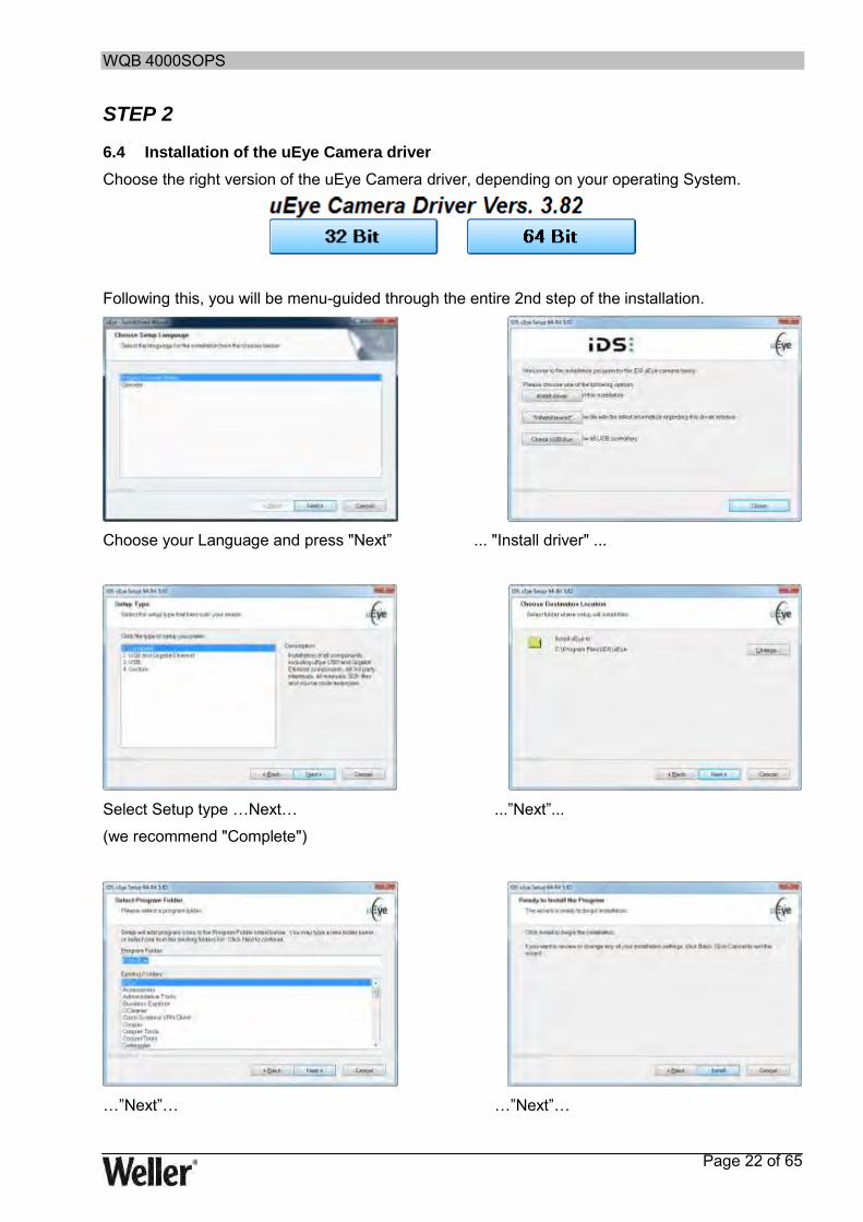
STEP 2
6.4 Installation of the uEye Camera driver
Choose the right version of the uEye Camera driver, depending on your operating System.
Following this, you will be menu-guided through the entire 2nd step of the installation.
Choose your Language and press "Next” ... "Install driver" ...
Select Setup type …Next… ...”Next”...
(we recommend "Complete")
…”Next”… …”Next”…

WQB 4000SOPS
Page 23 of 65
...”OK”… …”Next”…
Close Internet Explorer …”OK”…(for more information see 6.7)
…”Finish”

WQB 4000SOPS
Page 24 of 65
STEP 3
6.5 Installation of DirectX 9
The Installation of DirectX 9 is also necessary if you have already installed a newer DirectX version.
The installation process of DirectX 9 is started by clicking the mouse on the corresponding button.
Following this, you will be menu-guided through the entire 3rd step of the installation.
Accept the license agreements …”Next”…
and continue with “Next”
Wait …”Finish”…

WQB 4000SOPS
Page 25 of 65
STEP 4
6.6 Installation of the Weller WQB4000 Control software
The installation process of the WQB4000 Control software is started by clicking the mouse on the corresponding button.
Following this, you will be menu-guided through the entire 4th step of the installation.
…”Next”… Accept the license agreements
and continue with “Next”
Accept the license agreements …”Next”…
and continue with “Next”
…”Finish”
Restart the Computer after you have finished the Installation.
Following this, the installation is complete.
WQB 4000SOPS
Page 26 of 65
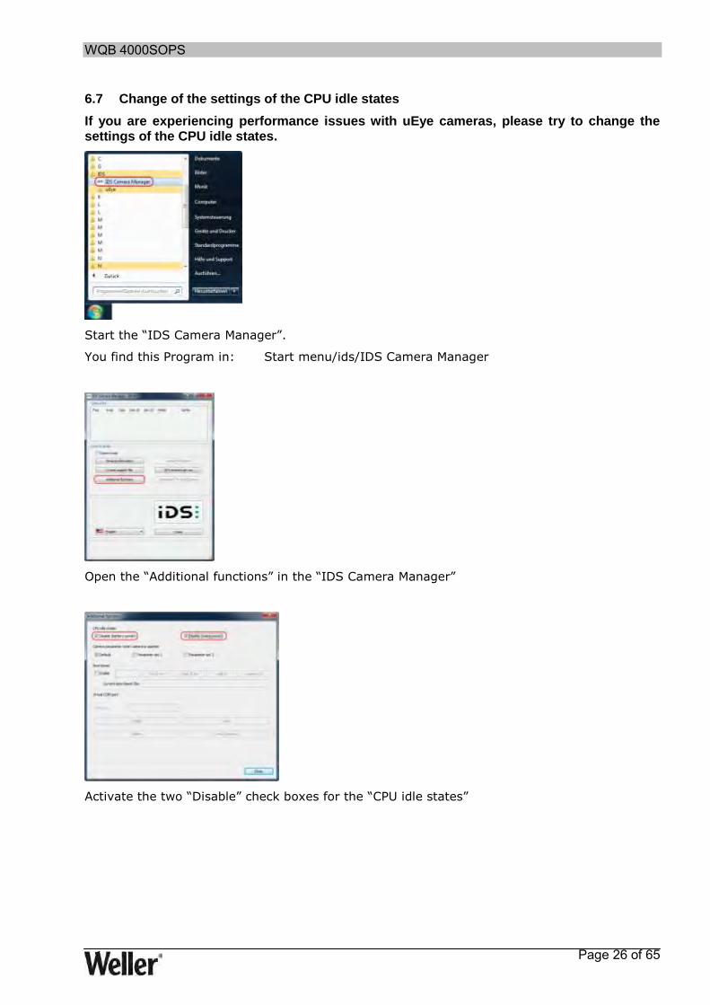
6.7 Change of the settings of the CPU idle states
If you are experiencing performance issues with uEye cameras, please try to change the settings of the CPU idle states.
Start the “IDS Camera Manager”.
You find this Program in: Start menu/ids/IDS Camera Manager
Open the “Additional functions” in the “IDS Camera Manager”
Activate the two “Disable” check boxes for the “CPU idle states”

WQB 4000SOPS
Page 27 of 65
6.8 Installation of the firmware updater
The installation of the firmware updater is not necessary for correct operation of the device; installation of this software is therefore only recommended if required.
The installation process of the optional firmware updater is started by clicking the mouse on the corresponding button.
The detailed installation process is described in the separate Installation Instructions of the Firmware Updater.
6.9 Uninstall
Back up your parameter blocks or measurement data files before
you uninstall the program from your system.
Before installing the software again, the existing installation must be removed completely.
During the installation in Windows, an entry was made in each case in the Control Panel in the Software section, which can be used to delete the software fully automatically.

WQB 4000SOPS
Page 28 of 65
6.10 Program Start
To start the software, select "Start => Programs => WQB4000Control“. When software is started, a dialog box for a reference run of the transportation table and the placement unit appears first. The soldering head must be raised and the split optical unit must be at the right-hand stop for the reference run. These positions are confirmed in the software with a green status display and enable the reference run. Start the reference run with "GO“.
6.11 Checking the split optical unit
1. In order to check, the Placement tab must be opened and the table must be in placement position
2. Insert the calibration template in the PCB holder and activate the frame or cross-hairs
3. Align calibration template centrally in relation to the faded in frame or cross-hairs (clamping screws of the PCB holder , micrometer screw )
4. Place component in template; the optical unit is at the left-hand stop
5. Align insertion head with centrally in relation to component
6. Move optical unit to right-hand stop (green LED)
7. Activate Automatic mode in the Z-axis drive
8. Set Pos. is used to lower the insertion head, automatically pick up the component and to move into Align Pos.
9. Important. Following this, the vacuum pick-up alignment must not be changed!
10. Move optical unit to the left
11. Use the arrow keys to adapt component and template to same size
12. The red and blue dots must now be flush.
13. If the dots are not in alignment, the optical unit must be calibrated (for exact description, see chapter 10.4 Calibration)
WQB 4000SOPS
Page 29 of 65
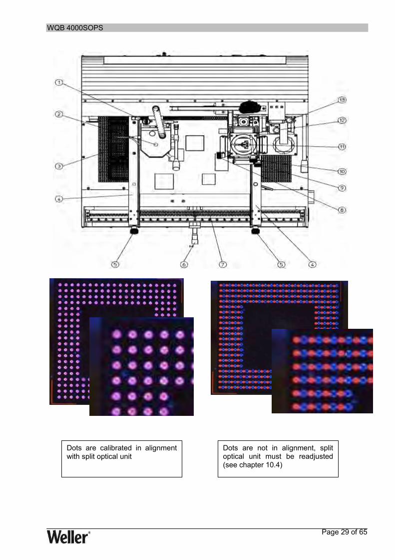
Dots are calibrated in alignment with split optical unit
Dots are not in alignment, split optical unit must be readjusted (see chapter 10.4)

WQB 4000SOPS
Page 30 of 65
7 Operation
7.1 Layout and function of operator interface
The user interface is divided into 2 elements. "Placement“ is required for the alignment and placement of components and "Soldering" for the soldering /desoldering process.
The illustration below shows the basic layout of the user interface. The areas are explained in brief in the following sections.
7.2 Standard buttons:
Exit: Close / exit the program
Axis Stop: immediate stop of the currently moved linear axes
Reference Axis: linear axes are traversed in reference position
Ext. Vacuum: pick-up of components by means of vacuum
<<< >>> : fast movement of table to left or right
<< >> : normal movement of table to left or right
< > : slow movement of table to left or right
Solder head: status display for position of soldering head
Split optic: status display for position of split optical unit
X-Axis Drive: control unit for the table
Component Pos.: position for picking up components
Soldering Pos.: position for soldering process
Center Pos.: Centre position of table
Placement Pos.: position for component alignment and placement
Absolut Position X: value of absolute position of table
WQB 4000SOPS
Page 31 of 65
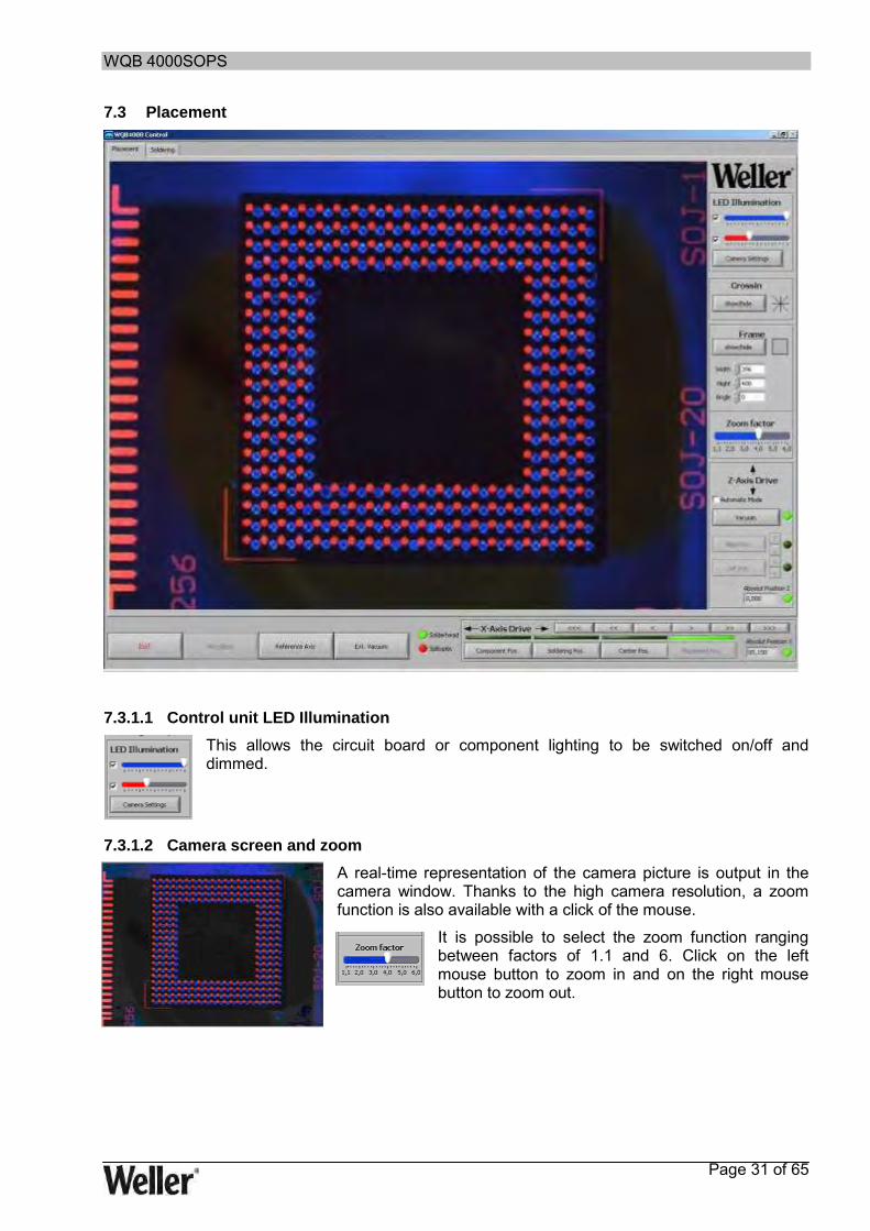
7.3 Placement
7.3.1.1 Control unit LED Illumination
This allows the circuit board or component lighting to be switched on/off and dimmed.
7.3.1.2 Camera screen and zoom
A real-time representation of the camera picture is output in the camera window. Thanks to the high camera resolution, a zoom function is also available with a click of the mouse.
It is possible to select the zoom function ranging between factors of 1.1 and 6. Click on the left mouse button to zoom in and on the right mouse button to zoom out.
WQB 4000SOPS
Page 32 of 65
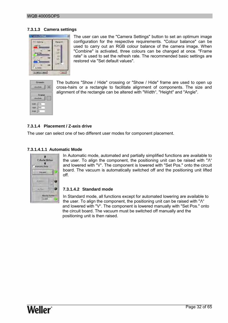
7.3.1.3 Camera settings
The user can use the "Camera Settings" button to set an optimum image configuration for the respective requirements. "Colour balance" can be used to carry out an RGB colour balance of the camera image. When "Combine" is activated, three colours can be changed at once. "Frame rate" is used to set the refresh rate. The recommended basic settings are restored via "Set default values".
The buttons "Show / Hide" crossing or "Show / Hide" frame are used to open up cross-hairs or a rectangle to facilitate alignment of components. The size and alignment of the rectangle can be altered with "Width“, "Height" and "Angle".
7.3.1.4 Placement / Z-axis drive
The user can select one of two different user modes for component placement.
7.3.1.4.1.1 Automatic Mode
In Automatic mode, automated and partially simplified functions are available to the user. To align the component, the positioning unit can be raised with "Λ“ and lowered with "V“. The component is lowered with "Set Pos." onto the circuit board. The vacuum is automatically switched off and the positioning unit lifted off.
7.3.1.4.2 Standard mode
In Standard mode, all functions except for automated lowering are available to the user. To align the component, the positioning unit can be raised with "Λ“ and lowered with "V“. The component is lowered manually with "Set Pos." onto the circuit board. The vacuum must be switched off manually and the positioning unit is then raised.

WQB 4000SOPS
Page 33 of 65
7.4 Soldering
7.4.1 Soldering profile bar graph
The bar graph provides a rapid overview of the duration of the soldering profile. The colours of the individual segments correspond to the times of the individual process steps.
7.4.2 Input boxes for process parameters
The process parameters can be divided into up to eight individual steps. The individual process parameters of a parameter block can be entered or edited in these input boxes. Depending on the requirement, a number between min. 1 and max. 8 steps is selected. In addition, the temperature sensor responsible for the control process can be selected.

WQB 4000SOPS
Page 34 of 65
A parameter block is made up of the following process parameters:
Steps Selection of number of steps 1 - 8
Nozzle off 1 - 8 Deactivation of top heater
Nozzle 1 - 8 Nozzle temperature for steps 1 – 8 / 50 °C – 400 °C
Airflow 1 - 8 Air throughput for step 1 – 8 / 5 – 50 l/min
Gradient 1 - 8 Temperature change for step 1 – 8 / -5 K - +5 K
Fault 1 - 8 Fault indicator for incorrect input
Bottom heater 1 - 8 Temperature of bottom heater for step 1 – 8 / 50 °C – 400 °C
Time 1 - 8 Time for step 1 – 8 / 0 sec. – 999 sec.
Fan Speed Fan speed as a percentage / 10-100 %
Buzzer Acoustic signal for confirming the end of the step
Standby Nozzle Standby temperature of nozzle / deactivated or 50 °C – 400 °C
Standby Preheat Standby temperature of bottom heater / deactivated or 50 °C – 400 °C
Preheat Size Size of bottom heater / small / large
Filename Name of currently opened file
Directory Target folder of currently opened file
Comment Comment box for entering a user-defined text
For every parameter block, the measured temperature profile chart including the set axis divisions are saved in addition. This makes it considerably easier to analyse the soldering profile afterwards.
7.4.3 Display LEDs for process step
The "Step 1" to "Step 8" LEDs indicate the relevant process step in the current process.
Using a suitable parameter selection, all steps can be assigned the following functions:
Preheating phase 1 / Preheat
Preheating phase 2 / Soak
Reflow / Peak
Cooling phase / Cooling

WQB 4000SOPS
Page 35 of 65
7.4.4 Saving and loading parameter blocks / profiles
The parameter blocks can be saved and loaded using the "Save“ and "Load“ buttons. The currently loaded parameter block is displayed in the program window at top left.
By loading a parameter block and saving under another name, changed / separate parameter blocks can be created.
7.4.5 Soldering / desoldering functions - runtime:
Preheat size: Switch-over to small / large bottom heater Vacuum: Switching vacuum pick-up on/off in soldering head Desoldering: Lowering of vacuum pick-up in soldering head Cooling: Switching fan on/off for cooling Start: Start of soldering / desoldering procedure Stop: Stopping soldering / desoldering process

WQB 4000SOPS
Page 36 of 65
7.4.6 Reinitialisation
The Re Init button can be used to reinitialise the communication between PC and WQB 4000SOPS without a software restart. Interrupted processes must be RESTARTED.
7.4.7 Language selection
The Language button allows you to select a language.
7.4.8 Celsius / Fahrenheit
Switch-over of temperature display from degrees Celsius to Fahrenheit and vice versa. 7.4.9 Process documentation
When the Excel File is activated, the automatic process documentation is started.
WQB 4000SOPS
Page 37 of 65
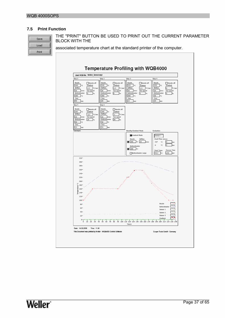
7.5 Print Function
THE "PRINT" BUTTON BE USED TO PRINT OUT THE CURRENT PARAMETER BLOCK WITH THE
associated temperature chart at the standard printer of the computer.
WQB 4000SOPS
Page 38 of 65
7.6 Special functions
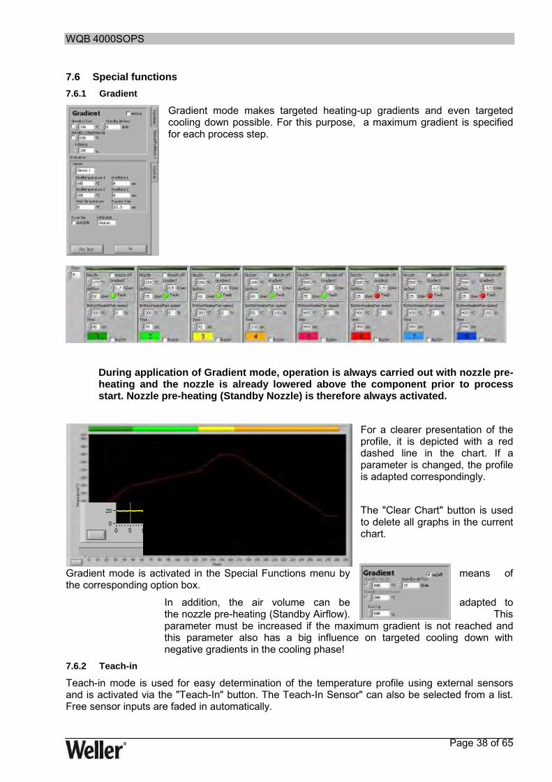
7.6.1 Gradient
Gradient mode makes targeted heating-up gradients and even targeted cooling down possible. For this purpose, a maximum gradient is specified for each process step.
During application of Gradient mode, operation is always carried out with nozzle pre-heating and the nozzle is already lowered above the component prior to process start. Nozzle pre-heating (Standby Nozzle) is therefore always activated.
For a clearer presentation of the profile, it is depicted with a red dashed line in the chart. If a parameter is changed, the profile is adapted correspondingly.
The "Clear Chart" button is used to delete all graphs in the current chart.
Gradient mode is activated in the Special Functions menu by means of the corresponding option box.
In addition, the air volume can be adapted to the nozzle pre-heating (Standby Airflow). This parameter must be increased if the maximum gradient is not reached and this parameter also has a big influence on targeted cooling down with negative gradients in the cooling phase!
7.6.2 Teach-in
Teach-in mode is used for easy determination of the temperature profile using external sensors and is activated via the "Teach-In" button. The Teach-In Sensor" can also be selected from a list. Free sensor inputs are faded in automatically.
Fig. 15 Chart with soldering profile

WQB 4000SOPS
Page 39 of 65
7.6.2.1 Automatic Teach-in
Automatic Teach-In is activated via "Automatic". During Automatic Teach-In, defined temperature thresholds are used to switch between the individual steps. These temperature thresholds are set by the process parameters. Teach-In is started like a normal soldering process.
7.6.2.2 Manual Teach-In
Manual Teach-in is activated by deactivating "Automatic". In Manual Teach-In, a switch is made to the next step by actuating "Start" in each case. Teach-In is started like a normal soldering process.

WQB 4000SOPS
Page 40 of 65
7.7 Other functions
7.7.1 Operating the soldering head and insertion head
The soldering head and the insertion head are guided by precision linear guides in the Z-axis.
The soldering head is equipped with a rotation-damped articulated lever (16). The soldering head can be lifted off or lowered without vibrations by operating the appropriate articulated lever. A component can also be lifted off during the desoldering process with the vacuum tube when the soldering head is lowered.
The insertion head is equipped with a stepping motor, which facilitates precise, software-controlled lowering and pick-up of components. Component pick-up with the insertion head (11) is performed with the vacuum nozzle (29). The vacuum is activated via "Vacuum" to lift up components. When lowered, the component can be placed fully automatically with the additional Automatic mode.
7.7.2 Component placement
For component placement, the component is picked up by the vacuum pick-up in "Component Pos." The transportation table must be moved to the "Placement Pos". When the component is raised, the split optical unit is pushed from the outer position between the component and circuit board and locked here. The lighting is switched on automatically. It is possible to compensate for any difference in size between the two picture by effect minimal movement of the positioning unit in the Z-direction. The component can be aligned in accordance with the pad layout on the circuit board using the adjusting screws for the X and Y directions (8) and (9) and the theta angle (10). The optical unit is extended to the right-hand stop, thereby releasing the positioning-unit electronics. When the positioning unit is lowered, the component is placed on the circuit board with a force of 2.7 N. The vacuum can be switched off fully automatically via a photoelectric barrier and the vacuum pick-up lifted off from the component. The table then moves automatically to "Soldering Pos.".

WQB 4000SOPS
Page 41 of 65
8 Maintenance and cleaning
8.1 Safety measures
8.1.1 The mains cable must only be inserted in the approved power sockets or adapters.
Use the supplied mains cable exclusively. 8.1.2 Keep your work area tidy and in proper order.
Do not bring combustible materials or objects near the hot soldering tool.
8.1.3 Take surrounding factors into consideration.
Do not use the soldering tool in a damp or wet environment.
8.1.4 Protect yourself against electric shocks.
Avoid touching earthed/grounded parts with your body, e.g. pipes, heating radiators, stoves and refrigerators.
8.1.5 Keep children away from work area.
Do not allow other persons to touch the soldering tool or accessories. Keep other persons away from your work area.
8.1.6 Store your soldering tool in a safe place.
Unused soldering tools should be stored in a dry, locked place out of the reach of children. Switch off all unused soldering tools so that they are de-energised and pressureless.
8.1.7 Do not overload your soldering tool.
Operate the soldering tool only at the specified voltage, at the specified pressure and in the specified pressure range.
8.1.8 Use the correct soldering tool.
Do not use a soldering tool whose power/performance is not sufficient for your work. Never use the soldering tool for purposes for which it is not designed.
8.1.9 Wear suitable work clothing.
Risk of burning with liquid solder. Wear appropriate protective clothing to protect yourself against burns.
8.1.10 Protect your eyes.
Wear protective goggles. When working with bonding agents, pay particular attention to the warning notices of the bonding-agent manufacturer. Protect yourself against solder splashes. Risk of burning with liquid solder.
8.1.11 Always use a soldering fume extraction device.
If facilities are available for connecting soldering fume extraction devices, make sure that these are connected and correctly used.
8.1.12 Do not use the cable for purposes for which it is not designed
Do not use the cable to pull the plug from the power socket. Protect the cable against heat, oil and sharp edges.
8.1.13 Secure the tool.
Use clamping devices to grip the workpiece. This is more secure than using your hands, and leaves both hands free to operate the soldering tool.
8.1.14 Avoid abnormal body posture.
Arrange your work area correctly in accordance with ergonomic considerations. Avoid bad posture when working. Always use the appropriate soldering tool.
WQB 4000SOPS
Page 42 of 65
8.1.15 Take care of your soldering tools.
Keep the soldering tool clean to ensure more exact and safer working. Follow the maintenance instructions. Regularly inspect all connected cables and hoses. Repairs may only be carried out by a recognised specialist. Only use original spare parts from WELLER®.
8.1.16 Remove the plug from the power socket before opening the unit.
8.1.17 Make sure all maintenance tools are removed.
Before switching on, check that all spanners and adjusting tools have been removed.
8.1.18 Avoid unintentional/accidental operation.
Make sure that the switch is turned off when inserting the plug into the power socket or connecting to the mains power supply.
8.1.19 Remain attentive.
Always pay attention to what you are doing. Work sensibly and cautiously. Do not use the soldering tool when you are not fully focused.
8.1.20 Inspect the soldering tool for any damage.
Before using the soldering tool further, inspect safety devices or slightly damaged parts for fault-free and intended operation. Check whether moving parts are working without faults and are not jamming or whether parts are damaged. All parts must be correctly mounted and all conditions for ensuring fault-free operation of the soldering tool must be satisfied. Damaged safety devices and parts must be correctly repaired or replaced by a recognised specialist repair shop, unless otherwise specified in the Operating Instructions.
8.1.21 Important
Only use original WELLER® accessories or auxiliary devices that are listed in the accessories list in the Operating instructions. Use of other tools and other accessories may cause injury.
8.1.22 Have your soldering tool repaired in an electrical service centre.
This soldering tool complies with the relevant safety regulations. Repairs must only be carried out by a qualified electrical service centre that uses original spare parts from WELLER®; otherwise operators run the risk of accidents.
8.1.23 Do not work on electrically live parts.
8.1.24 Do not connect combustible gases.
Do not connect inflammable gases to hot-air or hot-gas devices. Do not point the hot-gas jet at other persons or look into the hot-gas jet. Ensure adequate ventilation when using inert gases. Risk of suffocation.
8.1.25 Use with other WELLER®
devices.
If the soldering tool is to be used in conjunction with other WELLER® equipment or supplementary devices, also observe the warning notices set out in the accompanying Operating Instructions.
8.1.26 Observe the safety regulations applicable to your work area.
The bottom and top heater of the WQB 4000SOPS are only approved for heating components to be soldered / desoldered and related components / additional materials. If used for a purpose other than that specified in this document, warranty / liability claims shall immediately become invalid.

WQB 4000SOPS
Page 43 of 65
Fig. 2 Fig. 4
8.2 Maintenance and cleaning by users
- The linear axes or linear guide rails for moving the circuit board carriage or positioning unit must be lubricated after 5,000 process cycles or 1,000 operating hours at the latest.
Fig. 1
Fig. 2
Fig. 3
Fig. 4
Oil hole position
Fig. 1 Fig. 3

WQB 4000SOPS
Page 44 of 65
Sliding guides are maintenance-free.
We recommend MG10/CG2 from IKO NIPPON THOMSON CO. LTD
http://www.ikont.com
Before putting the WQB 4000SOPS into operation, always check for visible damage and completeness.
8.3 Cleaning agents
Clean the WQB 4000SOPS with a damp cloth and a commercially available cleaning agent. The application of liquid cleaning agents is prohibited. The covers for the electronics on the bottom side and on the heating head must not be removed for cleaning.
8.4 Troubleshooting, fault status diagnosis and repair
- Following start-up, the mechanical system is checked by the software and by a reference run.
- A visual check must be made of all other mechanical components for recognisable damage.
- After switching on, an LED display lights up in the EMERGENCY-STOP button as "POWERCONTROL".
- Following start-up, the motor control system is checked by the software and by a reference run.
- When the software is started, the safety switches are queried and confirmed by a GREEN LED display.
- After work is complete, move the circuit board carriage into CENTER position.
- Click on EXIT to close the software.
- Disconnect the mains connection by actuating the mains switch.
- The compressed air and nitrogen supply must be closed.
If the circuit board carriage and / or component placement unit become blocked, the mains connection must be disconnected by actuating the mains switch on the rear side. Close down the software. Then eliminate the blockage. (When de-energised, the motor-driven axes can be moved manually.) When the blockage has been eliminated, re-establish the mains connection and start up the software again. The interrupted process must be restarted.
In dangerous situations, the mains connection must be disconnected by actuating the EMERGENCY-STOP button on the front side. When restarting after elimination of a dangerous situation, the EMERGENCY-STOP button must be unlocked by turning it. Then close down the software and restart.
If the machine is shut down with the EMERGENCY-STOP button during the process, this process must be restarted during return to operation.

WQB 4000SOPS
Page 45 of 65
For more extensive repairs, please contact your nearest Customer Service.
- A fuse is replaced by removing the cover at the
device switch.
- The mains cable must be removed prior to changing a fuse.
- Only T10 A fuses must be used.

WQB 4000SOPS
Page 46 of 65
8.5 Possible faults
Fault Cause Remedy
No function No supply voltage Check mains connection
Check device fuse at mains switch
EMERGENCY STOP button is pressed
Unlock EMERGENCY-STOP button by turning to the left
Profile cannot be started Nozzle sensor defective/ not connected
Connect sensor / new sensor
Communication fault Check USB connection
Re-initialisation with Re Init button in the Special Functions menu
Soldering head not functioning, heater fault message
Soldering head overheated Shut down the system and allow to cool down
Heat conductor defective Contact the manufacturer
Fault message: No Air Compressed air / nitrogen not connected, or pressure is too low
Check / connect supply
No / insufficient vacuum No / insufficient pressure for compressed air supply
Check / connect supply
Vacuum lift in soldering head cannot be activated
No / insufficient pressure for compressed air supply
Check / connect supply
Table cannot be moved Soldering head in soldering position
Raise soldering head with operating lever
Z-axis not in placement position
Move Z-axis up
Reference points of X-axis or Z-axis are faulty
Reference run required
Z-axis cannot be moved Split optical unit not in right-hand position
Push split optical unit to the right/hand end stop
Reference points of X-axis or Z-axis are faulty
Reference run required
Camera image is blurred / too dark / too light
Object not focused Set image sharpness with focus ring on lens
Lens aperture opened too wide / closed
Set aperture opening with aperture ring on lens
Camera image inclined on screen
Camera not installed at a right angle on the split optical unit
Turn the camera by releasing the lens mount
Components are not correctly positioned when deposited
Split optical unit incorrectly adjusted
Readjust split optical unit (see Operating Instructions - Maintenance)

WQB 4000SOPS
Page 47 of 65
9 Optional modules and extras, specifications
Adjustable PCB stop WQB 005 87 548 73
For extensive accessories on hot-gas nozzles, see pages 53 + 54
Clamping set for circuit boards with difficult geometries 005 87 549 24
Support for large PCBs 005 87 557 45
NQ nozzle adapter for WQB 4000 005 87 549 70
Vacuum pipette 005 29 184 99
Object 10 X zoom 005 87 551 45
10 Maintenance and cleaning
10.1 Maintenance cycles for safe operation
The linear axes or linear guide rails for moving the circuit board carriage or positioning unit must be lubricated after 5,000 process cycles or 1,000 operating hours at the latest.
10.2 Customer Service address
Weller Tools GmbH Carl-Benz-Straße 2
74354 Besigheim, Germany
+49 (0) 7143580- 0 +49 (0) 7143 580- 108
10.3 Repacking
The WQB 4000SOPS must only be transported in the original transport packaging.
Prior to packing, all supply lines must be removed. The optical unit must be removed in reverse sequence to that described in chapter 5.3.1.1 and packed.

WQB 4000SOPS
Page 48 of 65
10.4 Calibration
We recommend that you carry out a reference run as described in chapter 6.1 before calibrating the split optical unit.
The transportation table is moved to the "Soldering Pos". Here, insert the adjustment template in the PCB holder and roughly align the cross-hairs pictured on the template to the middle of the soldering nozzle, i.e. the vacuum tube.
To do so, adjust the depth stop of the soldering head via the knurled screw so that the nozzle when lowered is approx. 0.5 - 1 mm above the template. To align the template precisely, lower the vacuum tube to the template and align the latter precisely.
Lift the soldering head off to release the transportation table. Then move the table to "Placement Pos.".
Knurled screw Vacuum tube
The top and bottom heaters must be deactivated and cold during adjustment so as to avoid the risk of burns.
Adjusting screws

WQB 4000SOPS
Page 49 of 65
The split optical element must be extended so that the component in the template can be lifted off with the vacuum pick-up. The vacuum tube should be aligned centrally to the component when the positioning unit is lowered with "Set Pos.". Otherwise set the distance with the "UP / DOWN" arrow keys to approx. 3 mm above the component. Now the vacuum tube is aligned centrally in relation to the component using the adjusting screws. To pick up the component, lower with the "DOWN" arrow key until contact is made with the component, pick up the component by means of "Vacuum Placement" and lift off with "Align Pos.".
After lifting off, do not alter either the table in X and Y directions or the positioning unit in X, Y and theta directions. Move the split optical unit to the left-hand stop until it engages between the adjustment component and adjustment template and activate the PCB lighting with the positioning software. The adjustment template is shown in red on the monitor. The optimum presentation of the template is achieved using the adjusting rings for the aperture and sharpness.
Example of the camera display

WQB 4000SOPS
Page 50 of 65
Camera settings
Switch on the component lighting to display the component on the screen. Slightly raise or lower the positioning unit with the "UP / DOWN" arrow keys to adapt the two images to the same size. To align the optical axis of the optical unit to the mechanical axis of the positioning unit, the positioning screws must first be loosened. Align the image of the template (red) in coincidence with the image of the component (blue) with the adjusting screw in X direction and the adjusting screw in Y direction and lock the split optical unit in position again. After locking, it is essential to check the image again and repeat the procedure if necessary.
The camera is aligned to the image centre in the factory and has to be checked by fading in the cross-hairs via "Show / Hide" Crossing or the rectangular frame via "Show / Hide" Frame (see chapter 7.3.1.3). In the event of deviations, the camera can be readjusted with the aid of the adjustable camera holder. To do so, release the securing screws on the relevant camera mount level, realign the camera mount and lock it again.
Adjusting screws
Positioning screws
Retaining screws

WQB 4000SOPS
Page 51 of 65
11 List of spare parts and consumables
11.1 Electrical system
Thermocouple type K, dia. 0.5 mm 005 31 190 99
Thermocouple type K, dia. 0.1 mm with plug 005 87 557 82
Temperature sensor PT 100 for top heater 005 87 549 48
USB 2.0 cable type A / type B 1.8 m 005 87 551 18
Heating element for top heater 005 87 549 77
11.2 Pneumatics
Vacuum tube for soldering head 005 87 549 47
Vacuum inserts dia. 4.5 mm (10 pieces) 005 87 137 99
Vacuum inserts dia. 10 mm (10 pieces) 005 87 137 98
Compressed air tube A dia. 6 mm 005 87 388 01
Y-connection for hose with A dia. 26 mm 005 87 570 86
11.3 Optical system
USB – camera 005 87 550 47
Camera lens 25 F1.4 005 87 550 48
USB 2.0 cable type Mini- A 1.8 m 005 87 551 12

WQB 4000SOPS
Page 52 of 65
11.4 Hot air nozzles
Article No. Nozzle housing, inside Nozzle housing, outside
mm x mm mm x mm
005 87 479 47 7.6 x 7.99 8.6 x 8.9
005 87 479 43 6.5 x 6.5 7.5 x 7.5
005 87 479 45 8.5 x 8.5 9.5 x 9.5
005 87 479 61 8.5 x 10.6 9.5 x 11.6
005 87 549 67 10.0 x 10.0 11.0 x 11.0
005 87 478 48 12.0 x 12.0 13.0 x 13.0
005 87 479 04 13.5 x 13.5 14.3 x 14.3
005 87 479 35 15.5 x 15.5 16.5 x 16.5
005 87 478 93 15.0 x 11.0 16.0 x 12.0
005 87 548 36 18.5 x 10.0 19.5 x 11.0
005 87 479 77 15.5 x 23.5 16.5 x 24.5
005 87 478 33 18.0 x 18.0 20.0 x 20.0
005 87 547 70 21.0 x 21.0 23.0 x 23.0
005 87 548 20 22.0 x 22.0 24.0 x 24.0
005 87 477 64 25.0 x 25.0 27.0 x 27.0
005 87 479 93 27.0 x 23.0 29.0 x 25.0
005 87 478 50 27.0 x 27.0 29.0 x 29.0
005 87 479 27 29.0 x 29.0 31.0 x 31.0
005 87 479 99 28.0 x 32.0 30.0 x 34.0
005 87 479 06 33.0 x 33.0 35.0 x 35.0
005 87 548 87 35.0 x 35.0 37.0 x 37.0
005 87 477 53 37.0 x 37.0 39.0 x 39.0
005 87 478 71 39.5 x 39.5 41.5 x 41.5
005 87 478 74 42.0 x 42.0 44.0 x 44.0
005 87 549 03 45.0 x 11.0 47.0 x 13.0
005 87 477 63 46.0 x 46.0 48.0 x 48.0
005 87 479 16 47.0 x 47.0 49.0 x 49.0
005 87 479 41 49.0 x 49.0 51.0 x 51.0
005 87 479 85 57.0 x 18.5 59.0 x 20.5

WQB 4000SOPS
Page 53 of 65
12 De-commissioning the product
When the designated machine service life (operating time) has been reached incl. the individual machine elements, dispose of the replaced device parts in accordance with national specifications. A RoHS conformity declaration exists for all parts.
- Transportation table in "Centre Pos."
- Switch off the mains voltage
- Disconnect the compressed air / nitrogen supply
- Remove the USB connections
- Disassemble the optical unit
- Pack in the transport packaging
13 Warranty
Claims based on defects will fall under the statute of limitations 12 months after delivery to the purchaser of the goods. This shall not apply to rights of recourse of the purchaser according to sections 478, 479 German Civil Code. We shall assume liability for warranties supplied by us only if the quality guarantee or service warranty has been submitted in writing and using the term "Warranty".

WQB 4000SOPS
Page 54 of 65
14 Figures
01 Depth stop for soldering head
07 Return springs for clamping arm
08 Micro-drive, X-adjustment
10 Micro-drive, theta adjustment
09 Micro-drive, Y-adjustment
11 Insertion head
02 Vacuum tube,
desoldering
(similar to figure)
WQB 4000SOPS
Page 55 of 65
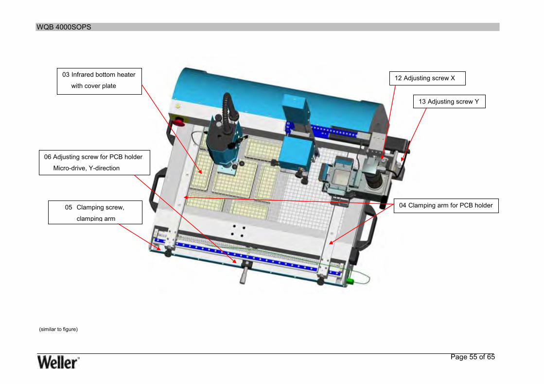
03 Infrared bottom heater
with cover plate
04 Clamping arm for PCB holder 05 Clamping screw,
clamping arm
06 Adjusting screw for PCB holder
Micro-drive, Y-direction
12 Adjusting screw X
13 Adjusting screw Y
(similar to figure)

WQB 4000SOPS
Page 56 of 65
(similar to figure)
24 PCB lighting (red)
25 Split optical unit
27 Camera focus
28 Camera aperture
26 Component lighting (blue)
30 Camera holder
31 Camera
29 Linear guide, split optical unit
32 Connection socket, lighting
33 Vacuum pick-up
14 Quick-release fastener for
soldering head
15 Theta adjustment for the soldering head
16 Articulated lever for the
soldering head
17 Height adjustment for vacuum tube
18 Soldering head
19 Connector socket
thermocouple
21 EMERGENCY STOP
20 PT 100 Temperature sensor 22 Hot-gas nozzle

WQB 4000SOPS
Page 57 of 65
36 3 x connections for thermocouple type K
37 Basic device with carrying grips
39 Fan
35 Traversing lever, split optical unit
40 Locking screw for
calibrating the split optical
unit
38 Adjustable PCB stop WQB
34 Split optical unit mount
23 Device foot
(similar to figure)

WQB 4000SOPS
Page 58 of 65
45 Connection, vacuum pipette
46 Nitrogen/compressed air supply, top heater
400-600 kPa
42 Device plug with mains switch
and fuse carrier (T10 A)
43 USB 2.0 interface for PC connection
41 Lock, split optical unit
44 Compressed air supply 400 - 600 kPa for
compressed air converter
(similar to figure)

WQB 4000SOPS
Page 59 of 65
15 Circuit diagrams
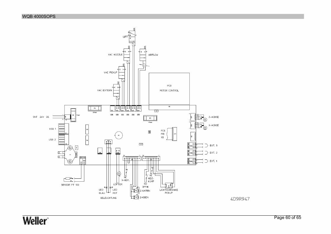
WQB 4000SOPS
Page 60 of 65

WQB 4000SOPS
Page 61 of 65
16 Notes

WQB 4000SOPS
Page 62 of 65
17 Index
A
Air consumption............................................................................................................................. 12 Air volume ..................................................................................................................................... 38
B
Basic settings ................................................................................................................................ 32 BGA .......................................................................................................................................... 9, 14 Blockage ....................................................................................................................................... 44 Bottom heater .................................................................................................... 9, 11, 12, 16, 34, 35 Boxed air level ............................................................................................................................... 16
C
Camera ....................................................................................................... 9, 11, 12, 16, 17, 18, 51 Change of workplace ..................................................................................................................... 14 Chart ............................................................................................................................................. 38 Circuit board .................................................................................................................. 9, 10, 11, 32 Circuit board carriage .................................................................................................................... 44 Circuit board size ........................................................................................................................... 11 Cleaning ...................................................................................................................... 41, 43, 44, 47 Cleaning agents ............................................................................................................................ 44 Colour depth .................................................................................................................................. 12 Commissioning .............................................................................................................................. 19 Component lighting ....................................................................................................................... 31 Component placement .................................................................................................................. 40 Compressed air ............................................................................................... 10, 12, 17, 18, 44, 53 Compressed air converter ............................................................................................................. 12 Compressed air hose ........................................................................................................ 16, 17, 51 Consumables ................................................................................................................................ 51 Contact protection ......................................................................................................................... 11 Control process ............................................................................................................................. 33 Cooling phase ............................................................................................................................... 39 Cross-hairs .................................................................................................................................... 32 Customer Service .................................................................................................................... 45, 47
D
Declaration of Conformity .............................................................................................................. 53 Desoldering ............................................................................................................................. 10, 51 Dimensions ............................................................................................................................. 12, 13 Disassembly .................................................................................................................................. 53 Disposal ........................................................................................................................................ 53
E
Electrical system ........................................................................................................................... 51 EMERGENCY STOP .............................................................................................................. 17, 44
WQB 4000SOPS
Page 63 of 65
F
Faults ............................................................................................................................................ 46 FINEPITCH ..................................................................................................................................... 9 Flow control ................................................................................................................................... 12
G
Gases ............................................................................................................................................ 42 Gradient .................................................................................................................................. 34, 38 Gradient mode .............................................................................................................................. 38
H
Heating element ...................................................................................................................... 10, 51 Hot air nozzles .............................................................................................................................. 52
I
Input boxes .................................................................................................................................... 33 Insertion head ................................................................................................................... 11, 16, 40 Installation ......................................................................................................................... 16, 19, 20
L
Language selection ....................................................................................................................... 36 Lens ............................................................................................................................ 11, 16, 18, 51
M
Mains fuse ..................................................................................................................................... 12 Mains supply voltage ................................................................................................... 12, 17, 18, 53 Maintenance ...................................................................................................................... 41, 43, 47 Maintenance tasks ........................................................................................................................ 14
N
Nitrogen ............................................................................................................................ 10, 17, 53 Noise ............................................................................................................................................. 13 Noise emission .............................................................................................................................. 12 Nozzle temperature ....................................................................................................................... 34
O
Operating Instructions ....................................................................................................... 13, 16, 42 Operating Manual .......................................................................................................................... 19 Optical system ............................................................................................................................... 51 Optical unit ............................................................................................................ 16, 17, 19, 47, 53
P
Packing ......................................................................................................................................... 53

WQB 4000SOPS
Page 64 of 65
Parameter ..................................................................................................................................... 38 Parameter block .................................................................................................................... 34, 35 PCB holder .............................................................................................................................. 11, 16 Pneumatics ................................................................................................................................... 51 Positioning unit .............................................................................................................. 9, 32, 43, 47 Power ...................................................................................................................................... 10, 12 Print function ................................................................................................................................. 37 Process documentation ................................................................................................................. 36 Process parameters ............................................................................................................ 9, 33, 39 Process step ........................................................................................................................... 34, 38
R
Re Init ............................................................................................................................................ 36 Referencing ............................................................................................................................. 19, 44 Reinitialisation ............................................................................................................................... 36 Repair ................................................................................................................................. 9, 14, 44 Replacement parts ........................................................................................................................ 51 Restart .................................................................................................................................... 19, 44
S
Safety regulations .......................................................................................................................... 42 Screen resolution .......................................................................................................................... 12 Software ............................................................................................................ 9, 16, 17, 19, 20, 44 Soldering fume extraction device ................................................................................................... 41 Soldering head ................................................................................................ 10, 16, 18, 19, 35, 40 Soldering process ...................................................................................................................... 9, 39 Soldering tool .......................................................................................................................... 41, 42 Start-up ......................................................................................................................................... 44 Step............................................................................................................................................... 34 Storage location ............................................................................................................................ 18 Strain relief .................................................................................................................................... 17 Supply lines ................................................................................................................................... 47 Switching on ............................................................................................................................ 42, 44
T
Teach-in ........................................................................................................................................ 39 Temperature control ................................................................................................................ 11, 12 Temperature profile determination ........................................................................................... 10, 39 Temperature sensor ............................................................................................................ 9, 16, 51 Temperature thresholds ................................................................................................................ 39 Thermocouple ............................................................................................................................... 51 Top heater ............................................................................................................... 9, 12, 16, 34, 51 Total weight ................................................................................................................................... 12 Transport packaging .................................................................................................... 14, 15, 18, 53 Transportation table .......................................................................................................... 11, 16, 53
U
USB ........................................................................................................... 11, 12, 14, 16, 17, 51, 53

WQB 4000SOPS
Page 65 of 65
V
Vacuum ............................................................................................................................. 10, 30, 32 Voltage .................................................................................................................................... 41, 42
W
Warning notes ................................................................................................................... 13, 41, 42 Warranty ....................................................................................................................................... 53 WIN 2000 SP4 .............................................................................................................................. 12 WIN Vista 32-Bit ........................................................................................................................... 12 WIN XP SP2 .................................................................................................................................. 12 Work area.......................................................................................................................... 19, 41, 42 WQB 4000SOPS ........................................................................ 9, 13, 14, 15, 16, 17, 18, 19, 44, 47 WQB4000 Control ......................................................................................................................... 19
Y
Y-distributor ............................................................................................................................. 16, 51
Z
Zoom ....................................................................................................................................... 18, 31 Zoom factor ................................................................................................................................... 31 Zoom function ............................................................................................................................... 31