Embed Size (px)
Citation preview

US
OPTIMUMM A S C H I N E N - G E R M A N Y
Operating manualVersion 1.1.3
Mill Drill
Article no. 333 84561
Article no. 333 8458

OPTIMUMM A S C H I N E N - G E R M A N Y
Version 1.1.3 dated 2015-1-19Page 2 Original operating instructions
BF46 Vario | BF46TCUS
Table of contents
1 Safety1.1 Type plate .................................................................................................................................................5
1.2 Safety instructions (warning notes)...........................................................................................................6
1.2.1 Classification of hazards...........................................................................................................................61.2.2 Other pictograms ......................................................................................................................................7
1.3 Proper use ................................................................................................................................................8
1.4 Reasonably foreseeable misuses.............................................................................................................8
1.4.1 Avoiding misuses......................................................................................................................................9
1.5 Possible dangers caused by the mill drill ................................................................................................10
1.6 Qualification of personnel .......................................................................................................................10
1.6.1 Target group ...........................................................................................................................................10
1.7 Operator positions ..................................................................................................................................11
1.8 Safety measures during operation..........................................................................................................11
1.9 Safety devices ........................................................................................................................................12
1.9.1 EMERGENCY STOP impact switch .......................................................................................................121.9.2 Lockable main switch..............................................................................................................................131.9.3 Protective cover ......................................................................................................................................131.9.4 Separating protective equipment ............................................................................................................13
1.10 Safety check ...........................................................................................................................................14
1.11 Personnel protective equipment .............................................................................................................14
1.12 For your own safety during operation .....................................................................................................15
1.13 Disconnecting and securing the mill drill.................................................................................................15
1.14 Using lifting equipment ...........................................................................................................................15
1.15 Position of labels on the mill drill.............................................................................................................16
2 Technical data2.1 Electrical connection...............................................................................................................................17
2.2 Drilling-milling capacity ...........................................................................................................................17
2.3 Spindle seat ............................................................................................................................................17
2.4 Drill-Mill head ..........................................................................................................................................17
2.5 Cross table..............................................................................................................................................17
2.6 Working area ..........................................................................................................................................17
2.10 Emissions ...............................................................................................................................................18
2.7 Speeds....................................................................................................................................................18
2.8 Environmental conditions........................................................................................................................18
2.9 Operating material ..................................................................................................................................18
3 Unpacking and connecting3.1 Scope of delivery ....................................................................................................................................19
3.2 Transport ................................................................................................................................................19
3.3 Storage ...................................................................................................................................................20
3.4 Installation and assembly .......................................................................................................................20
3.4.1 Requirements regarding the installation site...........................................................................................203.4.2 Load suspension point............................................................................................................................213.4.3 Assembly ................................................................................................................................................21
3.5 Dimensions, installation plan BF46V ......................................................................................................22
3.6 Dimensions, installation plan BF46TC....................................................................................................23
3.7 Installation plan of optional substructure ................................................................................................24
3.8 First commissioning ................................................................................................................................25
3.8.1 Power supply ..........................................................................................................................................253.8.2 Cleaning and lubricating .........................................................................................................................253.8.3 Filling in gear oil ......................................................................................................................................263.8.4 Warming up the machine........................................................................................................................263.8.5 Compressed air supply on BF46TC........................................................................................................26

OPTIMUMM A S C H I N E N - G E R M A N Y
Version 1.1.3 dated 2015-1-19 Page 3Original operating instructions
BF46 Vario | BF46TC US
3.9 Optional accessories .............................................................................................................................. 27
4 Operation4.1 Control and indicating elements BF46V ................................................................................................. 28
4.1.1 Control panel .......................................................................................................................................... 29
4.2 Switching on the mill drill ........................................................................................................................ 30
4.3 Switching off the mill drill ........................................................................................................................ 30
4.4 Inserting a tool on BF46V....................................................................................................................... 31
4.4.1 Installation .............................................................................................................................................. 314.4.2 Unfitting .................................................................................................................................................. 31
4.5 Threading ............................................................................................................................................... 32
4.6 Control and indicating elements BF46TC............................................................................................... 33
4.6.1 Control panel BF46TC............................................................................................................................ 34
4.7 Switching on the mill drill ........................................................................................................................ 35
4.8 Switching off the mill drill ........................................................................................................................ 36
4.9 Traveling the drilling milling head (Z-axis) upward respectively downward............................................ 36
4.9.1 Traveling the drill-mill head upward respectively downward by actuating the crank handle .................. 36
4.10 Threading ............................................................................................................................................... 37
4.10.1 Traveling the drill-mill head upward respectively downward using the control panel ............................. 37
4.11 Inserting a tool on BF46TC .................................................................................................................... 37
4.11.1 Installation .............................................................................................................................................. 374.11.2 Unfitting .................................................................................................................................................. 38
4.12 Safety ..................................................................................................................................................... 40
4.13 Use of collet chucks ............................................................................................................................... 40
4.14 Clamping the workpieces ....................................................................................................................... 40
4.15 Changing the speed range ..................................................................................................................... 40
4.16 Manual spindle sleeve feed with the fine feed........................................................................................ 41
4.17 Digital display for spindle sleeve travel .................................................................................................. 41
4.17.1 Malfunctions ........................................................................................................................................... 42
4.18 Manual spindle sleeve feed with the spindle sleeve lever ...................................................................... 43
4.19 Swivelling the drill-mill head ................................................................................................................... 43
4.20 Selecting the speed................................................................................................................................ 43
4.20.1 Standard values for cutting speeds ........................................................................................................ 444.20.2 Standard values for speeds with HSS – Eco – twist drilling (U.S. unit) .................................................. 45
5 Maintenance5.1 Safety ..................................................................................................................................................... 46
5.1.1 Preparation............................................................................................................................................. 465.1.2 Restarting ............................................................................................................................................... 46
5.2 Inspection and maintenance .................................................................................................................. 46
5.3 Repair ..................................................................................................................................................... 50
1 Spare parts1.1 Milling head 1 - 3 .................................................................................................................................... 51
1.2 Milling head BF 46 TC Vario .................................................................................................................. 52
1.3 Milling head 2 - 3 ................................................................................................................................... 53
1.4 Milling head 3 - 3 .................................................................................................................................... 54
1.5 Milling head BF46TC.............................................................................................................................. 54
1.6 Column ................................................................................................................................................... 55
1.7 Column BF46TC..................................................................................................................................... 56
1.8 Cross table 1 - 2 ..................................................................................................................................... 57
1.9 Cross table 2 - 2 ..................................................................................................................................... 58
1.10 Protection device.................................................................................................................................... 59
1.11 Machine stand (option)........................................................................................................................... 60
1.11.1 Spare parts list ....................................................................................................................................... 61
1.12 Wiring diagram 1 of 2/ BF46, BF46TC ................................................................................................... 66

OPTIMUMM A S C H I N E N - G E R M A N Y
Version 1.1.3 dated 2015-1-19Page 4 Original operating instructions
BF46 Vario | BF46TCUS
1.13 Wiring diagram 2 of 2/ BF46TC ..............................................................................................................67
1.13.1 Parts list electrical components BF46 Vario, BF46TC Vario ..................................................................68
1.14 Lubrication diagram ................................................................................................................................69
1.14.1 Lubricating unit .......................................................................................................................................69
2 Malfunctions
3 Appendix3.1 Copyright ................................................................................................................................................73
3.2 Terminology/Glossary.............................................................................................................................73
3.3 LIMITED WARRANTY ...........................................................................................................................74
Preface
Dear customer,
Thank you very much for purchasing a product made by OPTIMUM.
OPTIMUM metal working machines offer a maximum of quality, technically optimum solutions and convinceby an outstanding price performance ratio. Continuous enhancements and product innovations guaranteestate-of-the-art products and safety at any time.
Before commissioning the machine please thoroughly read these operating instructions and get familiar withthe machine. Please also make sure that all persons operating the machine have read and understood theoperating instructions beforehand. Keep these operating instructions in a safe place nearby the machine.
Information
The operating instructions include indications for safety-relevant and proper installation, operation and main-tenance of the machine. The continuous observance of all notes included in this manual guarantee the safetyof persons and of the machine.
The manual determines the intended use of the machine and includes all necessary information for its eco-nomic operation as well as its long service life.
In the paragraph "Maintenance" all maintenance works and functional tests are described which the operatormust perform in regular intervals.
The illustration and information included in the present manual can possibly deviate from the current state ofconstruction of your machine. Being the manufacturer we are continuously seeking for improvements andrenewal of the products. Therefore, changes might be performed without prior notice. The illustrations of themachine may be different from the illustrations in these instructions with regard to a few details. However,this does not have any influence on the operability of the machine. Therefore, no claims may be derived from the indications and descriptions. Changes and errors are reserved!
Your suggestion with regard to these operating instructions are an important contribution to optimising ourwork which we offer to our customers. For any questions or suggestions for improvement, please do not hesi-tate to contact us.
If you have any further questions after reading these operating instructions and you are not able tosolve your problem with a help of these operating instructions, please contact your specialiseddealer or
LDS Industries, LLC930 W. National Ave.Addison, IL 60101Tel.: 1-630-785-6437

OPTIMUMM A S C H I N E N - G E R M A N Y
Version 1.1.3 dated 2015-1-19 Page 5Original operating instructions
BF46 Vario | BF46TC US
1 Safety
This part of the operating instructions
explains the meaning and use of the warning references contained in the operating manual, explains how to use the lathe properly, highlights the dangers that might arise for you or others if these instructions are not obeyed, tells you how to avoid dangers.
In addition to this operating manual please observe
applicable laws and regulations, legal regulations for accident prevention, the prohibition, warning and mandatory signs as well as the warning notes on the mill drill.
Consult OSHA, state and local regulations in order to determine compliance, danger and risksto the operator.
Always keep this documentation close to the lathe.
If you would like to order another operating manual for your machine, please indicate the serialnumber of your machine. Please find the serial number on the type plate.
1.1 Type plate
INFORMATION
If you are unable to solve a problem using these operating instructions, please contact us foradvice:
Exclusive USA Agent
LDS Industries, LLC
930 W. National Ave.
Addison, IL 60101
Tel.: 1-630-785-6437

OPTIMUMM A S C H I N E N - G E R M A N Y
Version 1.1.3 dated 2015-1-19Page 6 Original operating instructions
BF46 Vario | BF46TCUS
1.2 Safety instructions (warning notes)
1.2.1 Classification of hazards
We classify the safety warnings into various levels. The table below gives an overview of theclassification of symbols (ideogram) and the warning signs for each specific danger and its(possible) consequences.
Ideogram Warning alert Definition / consequence
DANGER! Threatening danger that will cause serious injury or death to people.
WARNING! A danger that might cause severe injury to the staff or can lead to death.
CAUTION!Danger or unsafe procedure that might cause injury to people or damage to property.
ATTENTION!
Situation that could cause damage to the mill drill and products and other types of damage.
No risk of injury to people.
INFORMATION
Application tips and other important or useful information and notes.
No dangerous or harmful consequences for people or objects.
In case of specific dangers, we replace the pictogram by
or
general danger by a warning of injury of hands, hazardous electri-cal voltage,
rotating parts.

OPTIMUMM A S C H I N E N - G E R M A N Y
Version 1.1.3 dated 2015-1-19 Page 7Original operating instructions
BF46 Vario | BF46TC US
1.2.2 Other pictograms
Warning of danger of slipping!
Warning risk of stumbling! Warning hot surface! Warning biological hazard!
Warning of automatic start-up!
Warning tilting danger! Warning of suspended loads!
Caution, danger of explosive substances!
Activation forbidden! Read the operating instructions before
commissioning!
Disconnect the mains plug!
Use protective glasses! Use protective gloves! Use protective boots! Use protective suit!

OPTIMUMM A S C H I N E N - G E R M A N Y
Version 1.1.3 dated 2015-1-19Page 8 Original operating instructions
BF46 Vario | BF46TCUS
1.3 Proper use
WARNING!
In the event of improper use, the mill drill will endanger personnel, the mill drill and other material property of the operating company will be endan-
gered, the correct function of the mill drill may be affected.
The mill drill is designed and manufactured to be used for milling and drilling cold metals orother non-flammable materials or materials that do not constitute a health hazard by using com-mercial milling and drilling tools.
The mill drill must only be installed and operated in a dry and well-ventilated place.
If the mill drill is used in any way other than described above, modified without the approval ofthe company Optimum Maschinen Germany GmbH then the mill drill is being used improperly.
We will not be held liable for any damages resulting from any operation which is not in accord-ance with the intended use.
We would like to stress that any modifications to the construction, or technical or technologicalmodifications that have not been authorized will also render the warranty null and void.
It is also part of proper use that
the limits of the mill drill are observed, the operating manual is observed, the inspection and maintenance instructions are observed.
"Technical data“ on page 17
WARNING!
Heaviest injuries through improper use.
It is forbidden to make any modifications or alternations to the operation values of themill drill. They could endanger the staff and cause damage to the mill drill.
ATTENTION!
If the mill drill is not used as intended or if the safety directives or the operatinginstructions are ignored the liability of the manufacturer for any damages to persons orobjects resulting hereof is excluded and the claim under guarantee is becoming null andvoid!
1.4 Reasonably foreseeable misuses
Any other use as the one determined under the "Intended use" or any use beyond thedescribed use shall be deemed as not in conformity and is forbidden.
Any other use has to be discussed with the manufacturer.
It is only allowed to process metal, cold and non-inflammable materials with the mill drill.
In order to avoid misuses it is necessary to read and understand the operating instructionsbefore the first commissioning.
The operators must be qualified.
Use ear protection! Only switch in standstill! Protect the environment! Contact address

OPTIMUMM A S C H I N E N - G E R M A N Y
Version 1.1.3 dated 2015-1-19 Page 9Original operating instructions
BF46 Vario | BF46TC US
1.4.1 Avoiding misuses
Use of suitable cutting tools.
Adapting the speed adjustment and feed to the material and workpiece.
Clamp workpieces firmly and vibration-free.
ATTENTION!
The workpiece is always to be fixed by a machine vice, jaw chuck or by anotherappropriate clamping tool such as for the clamping claws.
WARNING!
Risk of injury caused by workpieces flying off.
Clamp the workpiece in the machine vice. Make sure that the workpiece is firmly clamped in themachine vice resp. that the machine vice is firmly clamped on the machine table.
Use cooling and lubricating agents to increase the durability of the tool and to improve the surface quality.
Clamp the cutting tools and workpieces on clean clamping surfaces.
Sufficiently lubricate the machine.
Correctly adjust the bearing clearance and the guidings.
It is recommended:
Insert the drill in a way that it is exactly positioned between the three clamping jaws of the quick action chuck.
Clamp and mills by means of the collet chuck and the corresponding collets.
Clamp end face mills by means of shell end mill arbors.
When drilling make sure that
the suitable speed is set depending on the diameter of the drill,
the pressure must only be such that the drill can cut without load
in case of too strong pressure the drill will get worn early or even might break resp. get jammed in the hole. If the drill gets jammed immediately stop the main motor by pressing the emergency stop button,
for hard materials, e.g. steel, use commercial cooling / lubricating agents,
generally always drive the turning spindle out of the workpiece.
ATTENTION!
Do not use the quick action drill chuck for milling tools. Never clamp a milling cutter intothe quick action drill chuck. Use a collet chuck and the corresponding collets for the endmill.
When milling make sure that
the corresponding cutting speed is selected,
for workpieces with normal strength values, e.g. steel 18-22 m/min,
for workpieces with high strength values 10-14 m/min,
the pressure is selected in a way that the cutting speed remains constant,
for hard materials commercial cooling / lubricating agents are used.

OPTIMUMM A S C H I N E N - G E R M A N Y
Version 1.1.3 dated 2015-1-19Page 10 Original operating instructions
BF46 Vario | BF46TCUS
1.5 Possible dangers caused by the mill drill
The mill drill is state-of-the-art.
Nevertheless, there is a residual risk as the mill drill operates with
at high speeds, with rotating parts and tools, with electrical voltages and currents.
We have used construction resources and safety techniques to minimize the health risk to per-sons resulting from these hazards.
If the mill drill is used and maintained by personnel who are not duly qualified, there may be arisk resulting from incorrect or unsuitable maintenance of the mill drill.
INFORMATION
Everyone involved in the assembly, commissioning, operation and maintenance must
be duly qualified, strictly follow these operating instructions.
Always disconnect the mill drill from the electrical power supply when performing cleaning ormaintenance works.
WARNING!
The mill drill may only be used with functional safety devices.
Disconnect the mill drill immediately, whenever you detect a failure in the safety devicesor when they are not fitted!
All additional devices installed by the operator have to be equipped with the prescribedsafety devices.
This is your responsibility being the operating company!
"Safety devices“ on page 12
1.6 Qualification of personnel
1.6.1 Target group
This manual is addressed to
the operating companies, the users, the staff for maintenance works.
Therefore, the warning notes refer to both, operation and maintenance staff of the mill drill.
Disconnect the mill drill always from the electrical power supply. This will prevent it from beingused by unauthorized staff.
The qualifications of the staff for the different tasks are mentioned below:
Operator
The operator is instructed by the operating company about the assigned tasks and possiblerisks in case of improper behaviour. Any tasks which need to be performed beyond the opera-tion in the standard mode must only be performed by the operator if it is indicated in theseinstructions and if the operating company expressively commissioned the operator.
Electrical specialist
Due to his professional training, knowledge and experience as well as his knowledge of respec-tive standards and regulations the electrical specialist is able to perform works on the electricalsystem and to recognise and avoid any possible dangers himself.

OPTIMUMM A S C H I N E N - G E R M A N Y
Version 1.1.3 dated 2015-1-19 Page 11Original operating instructions
BF46 Vario | BF46TC US
The electrical specialist is specially trained for the working environment in which he is workingand knows the relevant standards and regulations.
Specialist staff
Due to their professional training, knowledge and experience as well as their knowledge of rele-vant regulations the specialist staff is able to perform the assigned tasks and to recognise andavoid any possible dangers themselves.
Instructed persons
Instructed persons were instructed by the operating company about the assigned tasks and anypossible risks in case of improper behaviour.
INFORMATION
Everyone involved in the assembly, commissioning, operation and maintenance must
be duly qualified, strictly follow these operating instructions.
In the event of improper use
there may be a risk to the staff, there may be a risk to the mill drill and other material values, the correct function of the mill drill may be affected.
1.7 Operator positions
The operator’s position is in front of themill drill.
Fig.1-1: Operator positions
1.8 Safety measures during operation
CAUTION!
Risk due to inhaling of health hazardous dusts and mist.
Dependent on the material which need to be processed and the used auxiliaries dustsand mist may be caused which might impair you health.
Make sure that the generated health hazardous dusts and mist are safely sucked off atthe point of origin and is dissipated or filtered from the working area. To do so, use asuitable extraction unit.
CAUTION!
Risk of fire and explosion by using flammable materials or cooling lubricants.

OPTIMUMM A S C H I N E N - G E R M A N Y
Version 1.1.3 dated 2015-1-19Page 12 Original operating instructions
BF46 Vario | BF46TCUS
Before processing inflammable materials (e.g. aluminium, magnesium) or using inflam-mable auxiliary materials (e.g. spirit) it is necessary to take additional preventive meas-ures in order to safely avoid health risks.
1.9 Safety devices
Use the mill drill only with properly functioning safety devices.
Stop the mill drill immediately if there is a failure on the safety device or if it is not functioning forany reason.
It is your responsibility!
If a safety device has been activated or has failed, the mill drill must only be used if you
have removed the cause of the failure, have verified that there is no danger resulting for the staff or objects.
WARNING!
If you bypass, remove or deactivate a safety device in any other way, you areendangering yourself and other staff working with the mill drill. The possibleconsequences are injuries due to components or parts of components flying off at high speed, contact with rotating parts, fatal electrocution.
The mill drill includes the following safety devices:
an EMERGENY-STOP button, a protective cover on the drill / mill head. a separating protective device on the milling spindle,
WARNING!
The separating protective equipment which is made available and delivered togetherwith the machine is designed to reduce the risk of workpieces or fractions of them whichbeing expelled, but not to remove them completely. Always work carefully and observethe limit values of your chipping process.
1.9.1 EMERGENCY STOP impact switch
The EMERGENCY STOP push buttonswitches off the mill drill.
Fig.1-2: EMERGENCY STOP impact switch
ATTENTION!
The EMERGENCY-STOP push button stops the machine the moment it is activated.
Activate the emergency stop impact switch only in case of danger! If this push button isactuated in order to switch off the mill drill in the standard operation the tool orworkpiece might get damaged.
After having actuated the EMERGENCY STOP, turn the knob of the particular push button tothe right in order to restart the machine.
EMERGENCY-STOP

OPTIMUMM A S C H I N E N - G E R M A N Y
Version 1.1.3 dated 2015-1-19 Page 13Original operating instructions
BF46 Vario | BF46TC US
1.9.2 Lockable main switch
In the position " 0 " the lockable mainswitch can be secured against accidentalor non-authorized switching-on by meansof a padlock.
When the main switch is switched-off, thecurrent supply is interrupted.
Except for the areas marked by the picto-gram in the margin.
Fig.1-3: Main switch
WARNING!
Dangerous voltage even if the main switch is switched-off. In the areas marked by theideogram in the margin, there might be voltage, even if the main switch is switched off.
1.9.3 Protective cover
The drilling / milling head is equipped witha protective cover.
WARNING!
Only remove the protective coverwhen the mains plug of the mill drill isdisconnected.
Fig.1-4: Protective cover
1.9.4 Separating protective equipment
Adjust the protective equipment to thecorrect height before you start working.To do so, detach the clamping screw,adjust the required height and re-tightenthe clamping screw.
A switch is integrated in the fixture of thespindle protection which monitors that thecover is closed.
INFORMATION
You cannot start the machine if the spin-dle protection is not closed.
Fig.1-5: Separating protective equipment
Main switch
Protectivecover
Clamping screw

OPTIMUMM A S C H I N E N - G E R M A N Y
Version 1.1.3 dated 2015-1-19Page 14 Original operating instructions
BF46 Vario | BF46TCUS
1.10 Safety check
Check the mill drill in regular intervals.
Check all safety devices
before each operation, once a week (with the machine in operation), after every maintenance and repair work.
1.11 Personnel protective equipment
For certain work personal protective equipment is required.
Protect your face and your eyes: Wear a safety helmet with facial protection when performingworks where your face and eyes are exposed to hazards.
Use protective gloves when handling pieces with sharp edges.
Use safety shoes when you assemble, disassemble or transport heavy components.
Use ear protection if the noise level (emission) in the workplace exceeds 80 dB (A).
Before starting work make sure that the prescribed personnel protective equipment is availableat the working place.
CAUTION!
Dirty or contaminated personnel protective equipment can cause diseases. Clean it eachtime after use and once a week.
General check
Equipment Check OK
Protective covers Mounted, firmly bolted and not damaged
Signs,Markings
Installed and legible
Functional check
Equipment Check OK
EMERGENCY STOP impact switch
When the EMERGENCY STOP push button is activated, the mill drill must switch off. Make sure that it is only possible to restart the machine if the EMERGENCY STOP push button is unlocked and the ON switch was activated.
Separating safety device around the drilling and mill-ing spindle
The mill drill may switch on only when the safety device is closed.

OPTIMUMM A S C H I N E N - G E R M A N Y
Version 1.1.3 dated 2015-1-19 Page 15Original operating instructions
BF46 Vario | BF46TC US
1.12 For your own safety during operation
WARNING!
Before activating the mill drill assure yourself that this will neither endanger otherpersons nor cause damage to equipment.
Avoid any unsafe working practices:
Make sure that nobody is endangered by your work.
The instructions mentioned in these operating instructions have to be strictly observed dur-ing assembly, operation, maintenance and repair.
Wear safety goggles. Switch off the mill drill before measuring the workpiece. Do not work on the mill drill, if your concentration is reduced, for example, because you are
taking medication. Stay on the mill drill until the working spindle has come to a complete standstill. Use the prescribed personnel protective equipment. Make sure to wear a well-fitting work
suit and, if necessary, a hairnet. Do not use protective gloves during drilling or milling work. Disconnect the shock-proof plug from the outlet before replacing the tool. Use appropriate auxiliary materials to remove drilling and milling chips. Make sure that nobody is endangered by your work. Safely and firmly clamp the workpiece before switching on the mill drill.
We specially point out the specific dangers when working with and on the mill drill.
1.13 Disconnecting and securing the mill drill
Switch off the mill drill with the main switch before starting any maintenance and repair works.
1.14 Using lifting equipment
WARNING!
The use of unstable lifting and load suspension gear that might break under load cancause severe injuries or even death.
Check that the lifting equipment and load-suspension gears are of sufficient loadcapacity and are in perfect condition.
Observe the accident prevention regulations issued by your Employers LiabilityInsurance Association or other competent supervisory authority, responsible for yourcompany.
Fasten the loads properly.
Never walk under suspended loads!

OPTIMUMM A S C H I N E N - G E R M A N Y
Version 1.1.3 dated 2015-1-19Page 16 Original operating instructions
BF46 Vario | BF46TCUS
1.15 Position of labels on the mill drill
Fig.1-6: BF46 Vario | BF46TC

OPTIMUMM A S C H I N E N - G E R M A N Y
Version 1.1.3 dated 2015-1-19 Page 17Original operating instructions
BF46 Vario | BF46TC US
2 Technical data
The following information are the dimensions and indications of weight and the manufacturer‘sapproved machine data.
2.1 Electrical connection BF46 Vario BF46TC
Motor 3 HP, 230V, 1Ph, 60Hz
2.2 Drilling-milling capacity BF46 Vario BF46TC
Drilling capacity in steel 1.1" max. diam./28 mm
Drilling capacity in cast 1.2" max. diam./30 mm
Milling capacity end mill 1.3" max. diam./32 mm
Milling capacity milling head Ø 3.15" max. diam./80 mm
Swing 10.24"/ 260mm
2.3 Spindle seat BF46 Vario BF46TC
Spindle seat R8
optional
ISO 40 (DIN 2080, DIN 69871) MT4
Extraction rod (Draw-in rod) 7/16"
optional M16 (ISO 40)
Quill travel 4.5"/ 115 mm
2.4 Drill-Mill head BF46 Vario BF46TC
Swivelling + / - 45°
Gear stages 3
Travel of Z axis 21.3"/ 541 mm
2.5 Cross table BF46 Vario BF46TC
Table length 33.5"/ 850 mm
Table width 9.5"/ 240 mm
Travel of Y axis 10.2"/ 260 mm
Travel of X axis 20.5"/ 520 mm
T - slot size / number / distance [mm] 18 mm slots, three
Max. load [lbs] 385
2.6 Working area BF46 Vario BF46TC
Height 86.6"/ 2200 mm
Depth 78.7"/ 2000 mm
Width 102.4"/ 2600 mm
Total weight 1058 lbs./ 480 Kg

OPTIMUMM A S C H I N E N - G E R M A N Y
Version 1.1.3 dated 2015-1-19Page 18 Original operating instructions
BF46 Vario | BF46TCUS
2.10 Emissions
The generation of noise emitted by the mill drill is 80 dB(A).If the mill drill is installed in an area where various machines are in operation, the noise expo-sure (immission) on the operator of the mill drill at the working place may exceed 80dB(A).
INFORMATION
This numerical value was measured on a new machine under proper operating conditions.Depending on the age respectively on the wear of the machine it is possible that the noisebehaviour of the machine changes.
Furthermore, the factor of the noise emission is also depending on manufacturing influencingfactors, e.g. speed, material and clamping conditions.
INFORMATION
The mentioned numerical value is the emission level and not necessarily a safe working level.
Though there is a dependency between the degree of the noise emission and the degree of thenoise disturbance it is not possible to use it reliably to determine if further precaution measuresare required or not.
The following factors influence the actual degree of the noise exposure of the operator:
Characteristics of the working area, e.g. size or damping behaviour, Other noise sources, e.g. the number of machines, Other processes taking place in the proximity and the period of time during which the oper-
ator is exposed to the noise.
Furthermore, it is possible that the admissible exposure level might be different from country tocountry due to national regulations. This information about the noise emission shall allow the operator of the machine to more eas-ily evaluate the endangering and risks.
CAUTION!
Depending on the overall noise exposure and the basic limit values the machineoperators must wear an appropriate hearing protection.
We generally recommend to use a noise protection and a hearing protection.
2.7 Speeds BF46 Vario BF46TC
Gear stage slow [min-1] 115 - 720 RPM
Gear stage average [min-1] 324 - 1680 RPM
Gear stage rapid [min-1] 708 - 3100 RPM
2.8 Environmental conditions BF46 Vario BF46TC
Temperature 40 - 95 °F / 5 - 35 °C
Humidity 25 - 80%
2.9 Operating material BF46 Vario BF46TC
Gear Oil quantity 1-3/4 Qts. (1.7 L)
628 Mobil (Vis. 100/150) or a corresponding oil, see also "Lubricant“ on page 71
Bare steel parts Mobilux EP 004, acid-free oil, e.g. weapon oil, motor oil

OPTIMUMM A S C H I N E N - G E R M A N Y
Version 1.1.3 dated 2015-1-19 Page 19Original operating instructions
BF46 Vario | BF46TC US
3 Unpacking and connecting
INFORMATION
The mill drill is delivered pre-assembled.
3.1 Scope of delivery
Check immediately upon delivery of the mill drill if there are any transport damages or loos-ened fastening screws.
Compare the scope of delivery with the packing list.
3.2 Transport
WARNING!
Severe or fatal injuries may occur if parts of the machine tumble or fall down from theforklift truck or from the transport vehicle. Follow the instructions and information onthe transport case.
WARNING!
The use of unstable lifting and load suspension gear that might break under load cancause severe injuries or even death. Check that the lifting and load suspension gear hassufficient load capacity and that it is in perfect condition.
Observe the accident prevention regulations issued by your Employers LiabilityInsurance Association or other competent supervisory authority, responsible for yourcompany.
Fasten the loads properly.
Never walk under suspended loads!
Centres of gravity
Load suspension points(Marking of the positions for the load suspension gear)
Prescribed transportation position(Marking of the top surface)
Means of transport to be used
Weights

OPTIMUMM A S C H I N E N - G E R M A N Y
Version 1.1.3 dated 2015-1-19Page 20 Original operating instructions
BF46 Vario | BF46TCUS
3.3 Storage
ATTENTION!
In case of wrong and improper storage electrical and mechanical machine componentsmight get damaged and destroyed.
Store packed and unpacked parts only under the intended environmental conditions.
Follow the instructions and information on the transport case.
Consult Optimum Maschinen Germany GmbH if the machine and accessories are stored formore than three months or are stored under different environmental conditions than those givenhere.
3.4 Installation and assembly
3.4.1 Requirements regarding the installation site
Organize the working area around the drilling machine according to the local safety regulations.
INFORMATION
In order to attain good functionality and a high processing accuracy as well as a long durabilityof the machine the installation site should fulfil certain criteria.
Please observe the following points:
The device must only be installed and operated in a dry and well-ventilated place. Avoid places nearby machines generating chips or dust. The installation site must be free from vibrations also at a distance of presses, planing
machines, etc. The substructure must be suitable for the mill drill. Also make sure that the floor has suffi-
cient load bearing capacity and is level. The substructure must be prepared in a way that possibly used coolant cannot penetrate
into the floor. Any parts sticking out such as stops, handles, etc. have to be secured by measures taken
by the customer if necessary in order to avoid endangerment of persons.
Fragile goods(Goods require careful handling)
Protect against moisture and humid environment
"Environmental conditions“ on page 18.
Prescribed position of the packing case(Marking of the top surface - arrows pointing to the top)
Maximum stacking height
Example: not stackable - do not stack a second pack-ing case on top of the first one.

OPTIMUMM A S C H I N E N - G E R M A N Y
Version 1.1.3 dated 2015-1-19 Page 21Original operating instructions
BF46 Vario | BF46TC US
Provide sufficient space for the staff preparing and operating the machine and transporting the material.
Also consider that the machine is accessible for setting and maintenance works. Provide for sufficient illumination (Minimum value: 500 lux, measured at the tool tip). At little
intensity of illumination an additional illumination has to be ensured e.g. by means of a sepa-rate workplace lamp.
INFORMATION
The mains plug of the mill drill must be freely accessible.
3.4.2 Load suspension point
WARNING!
Danger of crushing and overturning. Proceed carefully when lifting, installing andassembling the machine.
Secure the load-suspension device around the drill-mill head. Use a lifting sling for this pur-pose.
Firmly clamp all clamping levers on the mill drill before lifting the mill drill.
Make sure that the load attachment does not cause damage to components or paint.
3.4.3 Assembly
Check if the underground of the mill drill is level using a spirit level.
Check if the underground is sufficiently stable and rigid. The total weight amounts to 1058 lbs./ 480 Kg.
ATTENTION!
Insufficient rigidity of the foundation leads to the superposition of the vibrations of the mill drill and of the underground (natural frequency of components).Critical speeds and moves in the axis with displeasing vibrations are rapidly achieved incase of insufficient rigidity of the whole system and will lead to bad milling results.
Place the mill drill on the provided underground.
Fix the mill drill in the provided through-holes on the machine foot.The attachment points are marked by arrows on the machine foot.
WARNING!
The condition of the underground and the fixing type of the machine foot to theunderground must be in a way that it can bear the loads of the mill drill. Theunderground must be level. Check if the underground of the mill drill is level using aspirit level.
Fix the foot of the mill drill to the substructure with the provided through-holes. We recommendyou to use shear connector cartridges resp. heavy-duty anchors.

OPTIMUMM A S C H I N E N - G E R M A N Y
Version 1.1.3 dated 2015-1-19Page 22 Original operating instructions
BF46 Vario | BF46TCUS
3.5 Dimensions, installation plan BF46V
A-A
A A
2.165" (55mm)
37.4" (950mm)
10.63" (270mm)
51.968
" (13
20mm
)
59.842
" (15
20mm
)
14.96" (380mm)
10.236" (260mm)
33.465" (850mm)
47.637" (1210mm)
15.354" (390mm)
4.72
" (12
0mm)
18.1"
(46
0mm)
15.748
" (400
mm)
18.897" (480mm)
Centre of gravity
17.322" (440mm)
27.56"
(70
0mm)
240
� 0.7
08" (18
mm)

OPTIMUMM A S C H I N E N - G E R M A N Y
Version 1.1.3 dated 2015-1-19 Page 23Original operating instructions
BF46 Vario | BF46TC US
3.6 Dimensions, installation plan BF46TC
A-A
A A
2.165"
(55
mm)
51.968
" (13
20mm
)
62.598
" (15
90mm
)
10.236" (260mm)
14.96" (380mm)
9.448" (240mm)
33.464" (850mm)
47.637" (1210mm)
� 0.708" (1
8mm)
4.72
4" (120m
m)
18.11
" (460
mm)
27.56"
(70
0mm)
15.354" (390mm)
17.323" (440mm)
15.748
" (4
00mm
)
17.72" (450mm)
10.63" (270mm)
Centre of gravity
38.97" (990mm)

OPTIMUMM A S C H I N E N - G E R M A N Y
Version 1.1.3 dated 2015-1-19Page 24 Original operating instructions
BF46 Vario | BF46TCUS
3.7 Installation plan of optional substructure
A-A
A A
33.464
" (850
mm)
34.842
" (885
mm)
21.653" (550mm)
23.622
" (600
mm)
29.527" (750mm)
24.41" (62
0mm)
�1829
.527
" (750
mm)
18.11
" (4
60mm
)
15.354" (390mm)
9.842" (250mm)
18.504
" (4
70mm
)
27.165" (690mm)� 0.5
9" (15mm
)

OPTIMUMM A S C H I N E N - G E R M A N Y
Version 1.1.3 dated 2015-1-19 Page 25Original operating instructions
BF46 Vario | BF46TC US
3.8 First commissioning
ATTENTION!
Before commissioning the machine check all screws, fixtures resp. safety devices andtighten up the screws if necessary!
WARNING!
Risk by using improper tool holders or operating them at inadmissible speeds.
Only use the tool holders (e.g. drill chuck) which were delivered with the machine orwhich are offered as optional equipment by OPTIMUM.
Only use tool holders in the intended admissible speed range.
Tool holders may only be modified in compliance with the recommendation of OPTI-MUM or of the manufacturer of the clamping devices.
WARNING!
When first commissioning the mill drill by inexperienced staff you endanger people andthe machine.
We do not take any liability for damages caused by incorrectly performed commission-ing.
"Qualification of personnel“ on page 10
3.8.1 Power supply
Connect the electrical supply cable.
Check the fusing (fuse) of your electrical supply according to the technical instructions regard-ing the total connected power of the mill drill.
3.8.2 Cleaning and lubricating
Remove the anti-corrosive agents on the mill drill which had been applied for transportation and storage. Therefore, we recommend you to use paraffin.
Do not use any solvents, cellulose thinner or any other cleaning agents which might affect the coating of the mill drill when cleaning the machine. Observe the indications and notes of the manufacturer for cleaning agents.
Oil all blank machine parts using an acid-free lubricating oil.
Lubricate the mill drill according to the lubricating plan. "Inspection and maintenance“ on page 46
Check if all spindles are running smoothly. The spindle nuts are re-adjustable.
Disassemble the V-ledges of the cross table and clean the ledges from the anti-corrosive agent. "V-ledges“ on page 49

OPTIMUMM A S C H I N E N - G E R M A N Y
Version 1.1.3 dated 2015-1-19Page 26 Original operating instructions
BF46 Vario | BF46TCUS
3.8.3 Filling in gear oil
The mill drill is delivered without oil filling. Fill in gear lubricantoil into the drill-mill head and the central lubrication unit.
"Oil change“ on page 48
3.8.4 Warming up the machine
ATTENTION!
If the mill drill and in particular the milling spindle is immediately operated at maximumload when it is cold it may result in damages.
If the machine is cold such as e.g. directly after having transported the machine it should bewarmed up at a spindle speed of only 500 rpm for the first 30 minutes.
3.8.5 Compressed air supply on BF46TC
Connect the compressed air supply with at least 87 psi (6 bars) to the quick-action coupling of the com-pressed air maintenance unit.
ATTENTION!
In order to ensure a failure-freeoperation of the machine it isnecessary that the required airpressure is continuously applied onthe machine at constant quality.
Fig.3-1: Compressed air supply
Compressed airservice unit

OPTIMUMM A S C H I N E N - G E R M A N Y
Version 1.1.3 dated 2015-1-19 Page 27Original operating instructions
BF46 Vario | BF46TC US
3.9 Optional accessories
Description Item No
Machine stand
Dimensions "Installation plan of optional substructure“
on page 24
335 3005
Vice 5" Precision Modular 3355553

OPTIMUMM A S C H I N E N - G E R M A N Y
Version 1.1.3 dated 2015-1-19Page 28 Original operating instructions
BF46 Vario | BF46TCUS
4 Operation
4.1 Control and indicating elements BF46V
Img.4-1: BF46 Vario | BF46TC
Pos. Designation Pos. Designation
1 Cover of draw-in rod 2 Control panel
3 Digital display fine crossfeed of spindlesleeve
4 Spindle protection
5 Crank for height adjustment of the drill-millhead
6 Selector switch for reduction stage
7 Star grip for spindle sleeve feed 8 Activation of the fine adjustment
9 Fine adjustment of spindle sleeve 10 Central lubrication
1
2
45
6
7
89
3
10
OPTIMUMM A S C H I N E N - G E R M A N Y
Version 1.1.3 dated 2015-1-19 Page 29Original operating instructions
BF46 Vario | BF46TC US
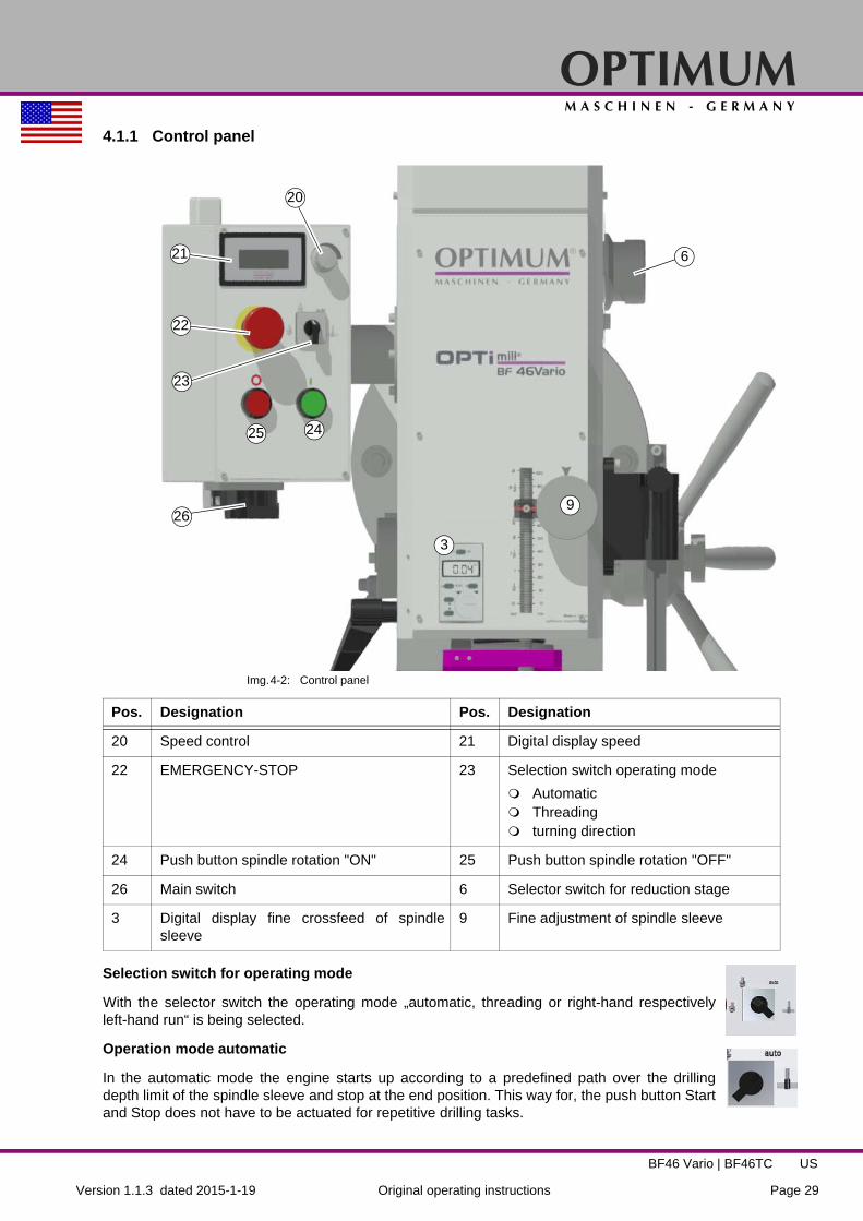
4.1.1 Control panel
Img.4-2: Control panel
Selection switch for operating mode
With the selector switch the operating mode „automatic, threading or right-hand respectivelyleft-hand run“ is being selected.
Operation mode automatic
In the automatic mode the engine starts up according to a predefined path over the drillingdepth limit of the spindle sleeve and stop at the end position. This way for, the push button Startand Stop does not have to be actuated for repetitive drilling tasks.
Pos. Designation Pos. Designation
20 Speed control 21 Digital display speed
22 EMERGENCY-STOP 23 Selection switch operating mode
Automatic Threading turning direction
24 Push button spindle rotation "ON" 25 Push button spindle rotation "OFF"
26 Main switch 6 Selector switch for reduction stage
3 Digital display fine crossfeed of spindlesleeve
9 Fine adjustment of spindle sleeve
20
21
22
2425
26
6
3
9
23
OPTIMUMM A S C H I N E N - G E R M A N Y
Version 1.1.3 dated 2015-1-19Page 30 Original operating instructions
BF46 Vario | BF46TCUS
Operation mode thread cutting
In the thread cutting mode the engine automatically starts up according to a predefined pathover the drilling depth stop and automatically changes the turning direction as soon as the pre-defined depth had been achieved. The screw-tap is drawn out of the workpiece.
Rotation direction switch
Standard operation, selection left-handed or right-handed rotation.
Potentiometer
Speed setting "VARIO"
Push button ON
The push button "ON" switches on the rotation of the spindle.
Push button OFF
The push button "OFF“ switches off the rotation of the spindle.
Main switch
Interrupts or connects the power supply.
4.2 Switching on the mill drill
Switch on the main switch.
Close the protective equipment.
Select the operating mode.
Select the gear level.
Set the potentiometer to the lowest speed.
Actuate push button "Start".
Set the required speed on the potentiometer.
ATTENTION!
Wait until the mill drill has come to a complete halt before changing the rotationdirection using the rotation direction switch.
INFORMATION
At a cold mill drill it is possible that with switching on the machine an overload of thedrive occur.
Therefore, allow the mill drill at low speeds depending on environmental conditions towarm up for 10 to 20 minutes before you go to maximum speed.
Also with a quick on and off, this overload occur. Therefore wait for about 3 secondsbefore you switch on the mill drill again, the capacitors in the controller must firstdischarged.
4.3 Switching off the mill drill
Press the push button spindle rotation "OFF". For a long-term standstill of the mill drill switch it off at the main switch.

OPTIMUMM A S C H I N E N - G E R M A N Y
Version 1.1.3 dated 2015-1-19 Page 31Original operating instructions
BF46 Vario | BF46TC US
4.4 Inserting a tool on BF46V
4.4.1 Installation
CAUTION!
When milling operations are performed the cone seat must always be fixed to the draw-in rod. All cone connections with the taper bore of the work spindle without using thedraw-in rod is not allowed for milling operations. The cone connection should bereleased by the lateral pressure. Injuries may be caused by parts flying off.
The milling head is equipped with a draw-in rod M16.
Remove the cap.
Clean the seat in the spindle / quill.
Clean the taper of your tool.
Insert the tool in the spindle / quill.
Img.4-3: Drilling and milling head
Screw the draw-in bar in the tool.
Tighten the tool with the draw-in rod and hold the spindle on the counter bearing by means of a wrench.
Img.4-4: Drilling-milling head without cap
4.4.2 Unfitting
Hold the spindle counter bearing with a wrench and loosen the draw-in rod. Continue turn-ing the draw -in rod, so that the tool is squeezed out from the conical collet.
ATTENTION!
When using an optional MT4 spindle.
When installing a cold morse taper into a heated-up machine those MT seats tend toshrink on the morse taper contrary to the quick-releaser tapers.
Cap
Draw-in rod
Steady/counter bearing

OPTIMUMM A S C H I N E N - G E R M A N Y
Version 1.1.3 dated 2015-1-19Page 32 Original operating instructions
BF46 Vario | BF46TCUS
4.5 Threading
Img.4-5: Operation mode thread cutting
Set the selection switch mode (23) to "threading" or "automatic".
Set the depth stop (26) to the desired depth.
Select the smallest speed.
Close spindle protection system.
Start the rotation of spindle (24).
Move the sleeve downward with the sleeve lever until the machine tap cams in the work-piece.
The machine tap turns into the workpiece. As soon as the preset depth is attained, the spindle reverses the direction of rotation at the switch point (28). The machine tap turns out of the work-piece. When the spindle sleeve is completely entered up to the switch point (27) in operation mode "automatic" the rotation of the spindle is stopped. Then it is possible to proceed another threading operation.
ATTENTION!
The spindle sleeve must be completely retracted in order to trigger the switch point (27).
Pos. Designation Pos. Designation
6 Selector switch for reduction stage 20 Speed control
23 Selection switch operating mode
automatic threading turning direction
24 Push button spindle rotation "ON"
26 Depth stop 27 Adjustable stop cycle end
28 End position switch turning directionreversal
6
26
23
26
27
28
24
23

OPTIMUMM A S C H I N E N - G E R M A N Y
Version 1.1.3 dated 2015-1-19 Page 33Original operating instructions
BF46 Vario | BF46TC US
4.6 Control and indicating elements BF46TC
Pos. Designation Pos. Designation
1 Pneumatic tool changer 2 Control panel
3 Digital display fine crossfeed of spindlesleeve
4 Clamping lever for spindle sleeve
5 Meter rule with scale 6 Motor Z-axis feed
7 Spindle protection 8 Activation of the fine adjustment
9 Fine adjustment of spindle sleeve 10 Central lubrication
11 Clamping lever for X-axis 12 Crank handle for saddle slide Y axis
13 Machine base (optionally) 14 Selector switch for reduction stage
15 Control panel tool change "CLAMPING" / "RELEASING"
16 Clamping screw drilling-milling head right
1
2
4
5
6
7
3
10
11
12
13
9
8
14
15
16
17
18
19
20
2021
22

OPTIMUMM A S C H I N E N - G E R M A N Y
Version 1.1.3 dated 2015-1-19Page 34 Original operating instructions
BF46 Vario | BF46TCUS
4.6.1 Control panel BF46TC
17 Star grip for spindle sleeve feed 18 Crank handle for manual height adjust-ment of the drilling milling head
19 Cross table 20 Adjustable limit stops
21 Handle of cross slide for X-axis 22 Clamping lever for Y-axis
Pos. Designation Pos. Designation
31
24
25
26
27
28
29
30
23
14
32
3
9
Pos. Designation Pos. Designation
23 Potentiometer speed control 24 Digital display speed
32 Control panel tool change:
Pushbutton "CLAMPING" Pushbutton "RELEASING"
26 Selection switch operating mode
automatic threading turning direction
27 Push button Z feed (travelling drilling milling head upward)
28 Push button spindle rotation "ON"
29 Push button Z feed (travelling drilling milling head downward)
30 Push button spindle rotation "OFF"
31 Main switch 14 Selector switch for reduction stage
3 Digital display fine crossfeed of spindlesleeve
9 Fine adjustment of spindle sleeve
25 EMERGENCY-STOP

OPTIMUMM A S C H I N E N - G E R M A N Y
Version 1.1.3 dated 2015-1-19 Page 35Original operating instructions
BF46 Vario | BF46TC US
Selection switch for operating mode
With the selector switch the operating mode „automatic, threading or right-hand respectivelyleft-hand run“ is being selected.
Operation mode automatic
In the automatic mode the engine starts up according to a predefined path over the drillingdepth limit of the spindle sleeve and stop at the end position. This way for, the push button Startand Stop does not have to be actuated for repetitive drilling tasks.
Operation mode thread cutting
In the thread cutting mode the engine automatically starts up according to a predefined pathover the drilling depth stop and automatically changes the turning direction as soon as the pre-defined depth had been achieved. The screw-tap is drawn out of the workpiece.
Rotation direction switch
Standard operation, selection left-handed or right-handed rotation.
Potentiometer
Speed setting "VARIO"
Push button ON
The push button "ON" switches on the rotation of the spindle.
Push button OFF
The push button "OFF“ switches off the rotation of the spindle.
Main switch
Interrupts or connects the power supply.
4.7 Switching on the mill drill
Switch on the main switch.
Close the protective equipment.
Select the operating mode.
Select the gear level.
Set the potentiometer to the lowest speed.
Actuate push button "Start".
Set the required speed on the potentiometer.
ATTENTION!
Wait until the mill drill has come to a complete halt before changing the rotationdirection using the rotation direction switch.
INFORMATION
At a cold mill drill it is possible that with switching on the machine an overload of thedrive occur.
Therefore, allow the mill drill at low speeds depending on environmental conditions towarm up for 10 to 20 minutes before you go to maximum speed.
OPTIMUMM A S C H I N E N - G E R M A N Y
Version 1.1.3 dated 2015-1-19Page 36 Original operating instructions
BF46 Vario | BF46TCUS
Also with a quick on and off, this overload occur. Therefore wait for about 3 secondsbefore you switch on the mill drill again, the capacitors in the controller must firstdischarged.
4.8 Switching off the mill drill
Press the push button "OFF". For a long-term standstill of the mill drill switch it off at the main switch.
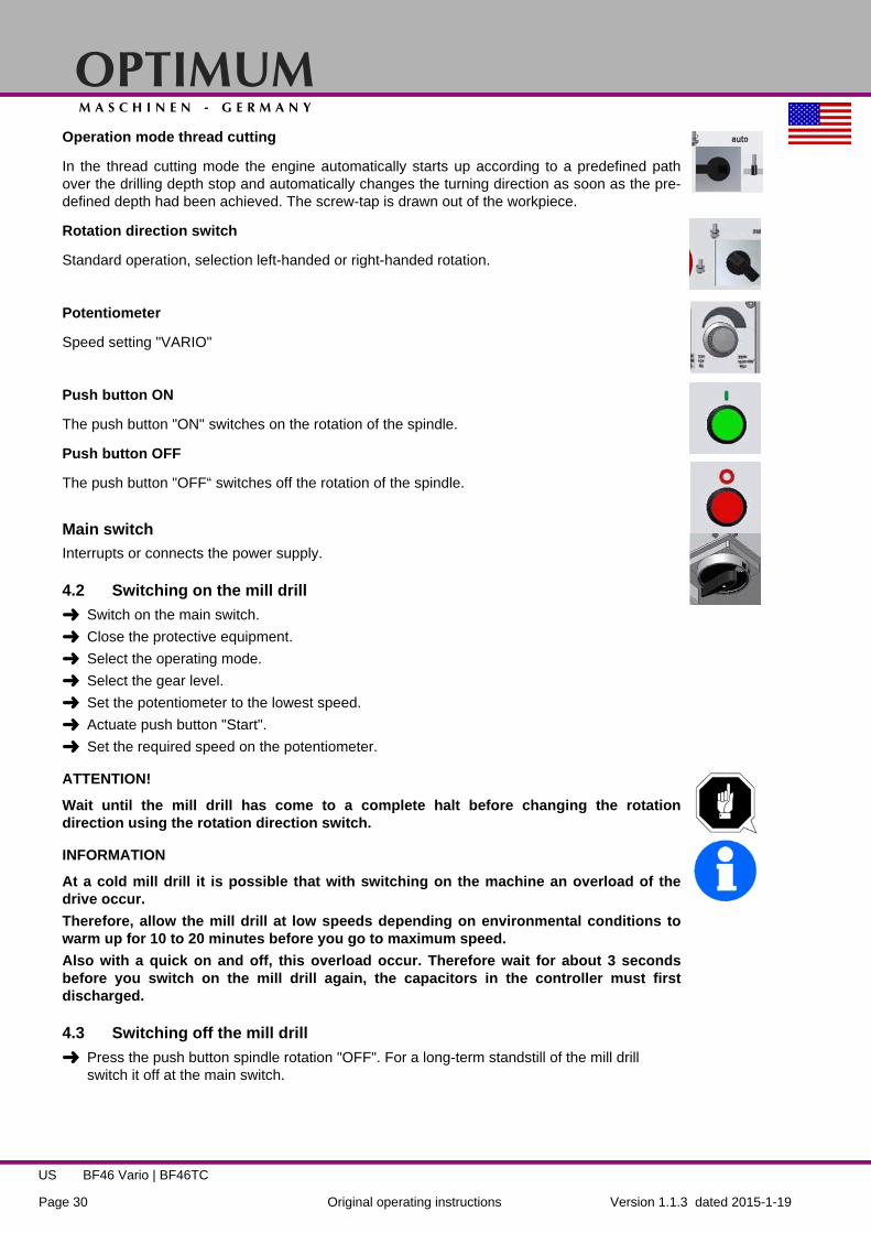
4.9 Traveling the drilling milling head (Z-axis) upward respectively downward
It is possible to perform the height adjustment of the drilling milling head by actuating the crankhandle or the control panel
4.9.1 Traveling the drill-mill head upward respectively downward by actuating the crank handle
Img.4-6: Drilling milling head - height adjustment
Img.4-7: Clamping lever
Release clamping lever (2).
Engage the handle (1) by pushing it towards the teeth.
Crank the drilling milling head to the required position.
Clamp if needed.
1
2
1 Crank handle
2 Clamping lever

OPTIMUMM A S C H I N E N - G E R M A N Y
Version 1.1.3 dated 2015-1-19 Page 37Original operating instructions
BF46 Vario | BF46TC US
4.10 Threading
as described under "Threading“ on page 32
4.10.1 Traveling the drill-mill head upward respectively downward using the control panel
Img.4-8: Traveling the drilling milling head upward respectively downward using the control panel
Press the button (1) in order to travel the drilling milling head upward.
Press the button (2) in order to travel the drilling milling head downward.
The end switch (3) limits the vertical movement of the drilling milling head upward respectivelydownward.
4.11 Inserting a tool on BF46TC
4.11.1 Installation
CAUTION!
When milling operations are performed the cone seat must always be fixed to the draw-in rod. All cone connections with the taper bore of the work spindle without using thedraw-in rod is not allowed for milling operations. The cone connection should bereleased by the lateral pressure. Injuries may be caused by parts flying off.
The milling head is equipped with a pneumatic tool changer and a M16 extraction rod (draw inbar).
1
2
3
1 Traveling the drilling milling head upward
2 Traveling the drilling milling head downward
3 End switch
OPTIMUMM A S C H I N E N - G E R M A N Y
Version 1.1.3 dated 2015-1-19Page 38 Original operating instructions
BF46 Vario | BF46TCUS
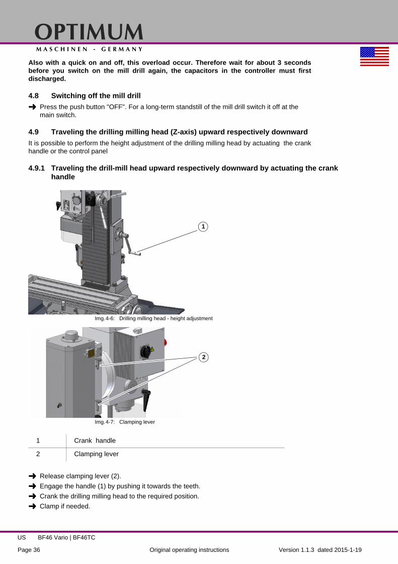
Clean the seat in the spindle / quill.
Clean the taper of your tool.
Insert the tool in the spindle / quill.
Img.4-9: Installation tool
Clamp the tool fixture by actuating the pressure switch "Clamping" on the control panel. The fixture will be drawn into the spindle. Press the push button switch until the tool is securely clamped.
ATTENTION!
Img.4-10: Installation tool
Make sure that the tool seat is correctly positioned (ISO 40).
The tool clamping system must not be activated when the machine is operated.
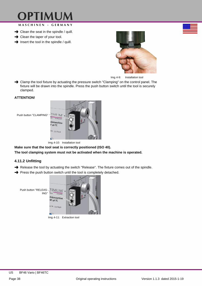
4.11.2 Unfitting
Release the tool by actuating the switch "Release“. The fixture comes out of the spindle.
Press the push button switch until the tool is completely detached.
Img.4-11: Extraction tool
Push button "CLAMPING“
Push button "RELEAS-ING"

OPTIMUMM A S C H I N E N - G E R M A N Y
Version 1.1.3 dated 2015-1-19 Page 39Original operating instructions
BF46 Vario | BF46TC US
ATTENTION!
Hold the tool fixture tight when you detach it. The toolfixture is pressed out of the spindle.
ATTENTION!
The tool clamping system must not be activated whenthe machine is operated.
Img.4-12: Extraction tool
ATTENTION!
When using an optional MT4 spindle.
When installing a cold morse taper into a heated-up machine those MT seats tend toshrink on the morse taper contrary to the quick-releaser tapers.

OPTIMUMM A S C H I N E N - G E R M A N Y
Version 1.1.3 dated 2015-1-19Page 40 Original operating instructions
BF46 Vario | BF46TCUS
4.12 Safety
Commission the mill drill only under the following conditions:
The mill drill is in proper working order. The mill drill is used as intended. The operating manual is followed. All safety devices are installed and activated.
All failures should be eliminated immediately. Stop the mill drill immediately in the event of anyabnormality in operation and make sure it cannot be started up accidentally or without authori-sation.
"For your own safety during operation“ on page 15
4.13 Use of collet chucks
When using collet chucks for the reception of milling tools, a higher operation tolerance can beachieved. The exchange of the collet chucks for a smaller or larger end mill cutter is performedsimply and rapidly and it is not necessary to disassemble the complete tool. The collet chuck ispressed into the ring of the swivel nut and must rest there by itself. The milling cutter is clampedby fastening the swivel nut on the tool.
Make sure that the correct collet chuck is used for each milling cutter diameter, so that the mill-ing cutter may be fastened securely and firmly.
"Compressed air supply on BF46TC“ on page 26
4.14 Clamping the workpieces
CAUTION!
Injury by flying off parts.
The workpiece is always to be fixed by a machine vice, jaw chuck or by anotherappropriate clamping tool such as for the clamping claws.
4.15 Changing the speed range
ATTENTION!
Wait until the mill drill has come to a complete halt before changing the speed using thegear switch.
Select gear levelH = rapid ( 708 - 3100 RPM )M = middle ( 324 - 1680 RPM )L = low ( 115 - 720 RPM )
Adjust the speed with the potentiome-ter. The speed and thus the cutting speed depends on the material of the workpiece, the milling cutter diameter and the cutter type.
Img.4-13: Drill-Mill head
Selector switchgear stage

OPTIMUMM A S C H I N E N - G E R M A N Y
Version 1.1.3 dated 2015-1-19 Page 41Original operating instructions
BF46 Vario | BF46TC US
4.16 Manual spindle sleeve feed with the fine feed
Turn the handle screw.The spindle sleeve lever moves in direction of the drilling-milling head and activates the coupling of the fine feed.
Turn the spindle sleeve fine feed in order to move the spindle sleeve.
Img.4-14: Handle screw
4.17 Digital display for spindle sleeve travel
Handle screw
Fine feed forspindle sleeve
Measuring range0 - 999.99mm
0 - 39.371“
Reading precision0.01mm
0.0004“
Power supply round cell CR2032 , 3 V 20 x 3,2mm
Pos. Designation
1 LCD display
2 Shifting mm/inch
3 Performs a value increase in operating mode "S" (Setting)
4 Performs a value decrease in operating mode "S" (Setting)
5 ON/OFF switch
6 Zero position and activation of operation mode "S"
7 Battery bay
8 Display of operation mode "S" and selected unit "mm / inch"
1
2
5
6
73
8
4

OPTIMUMM A S C H I N E N - G E R M A N Y
Version 1.1.3 dated 2015-1-19Page 42 Original operating instructions
BF46 Vario | BF46TCUS
Operation mode "S"
The operation mode "S" is used to enter and to compensate the mechanical play (backlash) ofquill mechanism.
(1) Display which shows the operating modes "S", "inch" or "mm" (2) converts the measuring unit from millimetres to inches and vice versa. (3) , Value increase in operation mode "S" (4) , Value decrease in operation mode "S" (5) Switches the display ON or OFF. Resets the display to the set compensation value "S".
Enter the offset value of the quill mechanism
Press the button (6) for about 2-3 seconds. The operation mode (8) "S" is activated and dis-played.
Enter the offset value of a quill mechanism, based on your experience with the keys (3) or (4).
Stop the operation mode "S" by pressing the button (6) again.
INFORMATION
Before inserting the new battery, wait about 30 seconds. Please make sure, that the contactsare metallically bright and free from coverings which result from bleeding or gassing batteries.Grip the new batteries only with plastic forceps, if possible not with the hand due to the forma-tion of oxide and never with metal forceps in order to avoid a short circuit. In most cases theround cell will be inserted into the digital display with the marking upside. After inserting theround cell, the battery compartment has to be closed again.
4.17.1 Malfunctions
Malfunction Cause / possible effects Solution
Flashing of the dis-play
• Voltage too low • Change battery
Screen doesn’t refresh
• Operation mode "S" is active• Disturbance in the circuit
• Disable the operation mode "S".• Remove the battery, wait 30 seconds and
reinsert the battery.
No data visible • No power supply• Battery voltage less than 3V
• Clean battery contacts• Replace battery

OPTIMUMM A S C H I N E N - G E R M A N Y
Version 1.1.3 dated 2015-1-19 Page 43Original operating instructions
BF46 Vario | BF46TC US
4.18 Manual spindle sleeve feed with the spindle sleeve lever
ATTENTION!
The clutch of the fine feed has to be disengaged before the spindle sleeve lever can beused. Activating the spindle sleeve lever when the fine feed is engaged may damage theclutch.
Loosen the handle screw. The sleeve lever moves away from the drilling head and deacti-vates the coupler of the fine feed.
4.19 Swivelling the drill-mill head
The drill-mill head may be swivelled 45°to the right and to the left. There are toloosen three screws.
Img.4-15: Clamping screws
CAUTION!
If the screws are completely unfastened, the drilling-milling head might fall down. Whenslewing the working head, only unfasten the screws as far as necessary to be able toperform the settings. After having set the slewing angle, retighten the fixing screws.
ATTENTION!
The drill-mill head can be rotated much further. When slewing it further on gear oil mightescape.
4.20 Selecting the speed
For milling operations, the essential factor is the selection of the correct speed. The speeddetermines the cutting speed of the cutting edges which cut the material. By selecting the cor-rect cutting speed, the service life of the tool is increased and the working result is optimised.
The optimum cutting speed mainly depends on the material and on the material of the tool. Withtools (milling cutters) made of hard metal or ceramic insert it is possible to work at higherspeeds than with tools made of high-alloyed high-speed steel (HSS). You will achieve the cor-rect cutting speed by selecting the correct speed.
In order to determine the correct cutting speed for your tool and for the material to be cut, youmay refer to the following standard values or a table reference book (e.g. Machinery'sHandbook ISBN 0-8311-2424-5, Insert Pgs. 30a & 30b (attached)).
The required speed is calculated as follows:
Clamping screws

OPTIMUMM A S C H I N E N - G E R M A N Y
Version 1.1.3 dated 2015-1-19Page 44 Original operating instructions
BF46 Vario | BF46TCUS
4.20.1 Standard values for cutting speeds
[FPM] with high-speed steel and hard metal in conventional milling
Given below are standard values for speeds depending on the milling cutter diameter, cuttertype and material.
Tool Steel Grey Cast IronAge- Hardened
Al alloy
Peripherial and side milling (FPM) 33 - 82 33 - 72 492 - 1,148Relieved form cutters (FPM) 49 - 79 33 - 66 492 - 820
Inserted tooth cutter with SS (FPM) 49 - 79 39 - 82 656 - 984
Inserted tooth cutter with HM (FPM) 328 - 656 98 - 328 984 - 1,312
Tool diameter (in.)
Peripheral and side milling cuttersSteel Grey Cast Iron
Age-Hardened Al alloy
33 - 82 FPM 33 - 72 FPM 492 - 1,148 FPM
Speed (RPM)1.378" 91 - 227 91 - 200 1,365 - 3,185
1.575" 80 - 199 80 - 175 1,195 - 2,790
1.772" 71 - 177 71 - 156 1,062 - 2,4701.969" 64 - 159 64 - 140 955 - 2,2302.165" 58 - 145 58 - 127 870 - 2,0272.362" 53 - 133 53 - 117 795 - 1,8602.559" 49 - 122 49 - 108 735 - 1,715
Tool diameter (in.)
Form cuttersSteel Grey Cast Iron
Age-Hardened Al alloy
49 - 79 FPM 33 - 66 FPM 492 - 820 FPMSpeed (RPM)
0.1575" 1,194 - 1,911 796 - 1,592 11,900 - 19,0000.1969" 955 - 1,529 637 - 1,274 9,550 - 15,9000.2362" 796 - 1,274 531 - 1,062 7,900 - 13,2000.3150" 597 - 955 398 - 796 5,900 - 9,9000.3937" 478 - 764 318 - 637 4,700 - 7,9000.4724" 398 - 637 265 - 531 3,900 - 6,6000.5512" 341 - 546 227 - 455 3,400 - 5,6000.6299" 299 - 478 199 - 398 2,900 - 4,900

OPTIMUMM A S C H I N E N - G E R M A N Y
Version 1.1.3 dated 2015-1-19 Page 45Original operating instructions
BF46 Vario | BF46TC US
4.20.2 Standard values for speeds with HSS – Eco – twist drilling (U.S. unit)
1: Speed (n) in RPM
2: Feed Rate (f) in./rev.
3: Coolant: E = Emulsion; Oil = Cutting oil
The above mentioned indications are standard values. In some cases it may be advantageous to increase or decrease these values.
When drilling a cooling or lubricating agent should be used.
For stainless materials (e.g. VA – or NIRO steel sheets) do not center as the material would compact and the drill bit will become rapidly blunt.
The workpieces need to be tensed in flexibly and stably (vice, screw clamp).
INFORMATION
High temperatures are generated at the tip of the tool by the occurring friction heat. The toolshould be cooled during the milling process. Cooling the tool with a suitable cooling lubricantensures better working results and a longer edge life of the cutting tool.
INFORMATION
Use a water-soluble and non-pollutant emulsion as a cooling agent.This can be acquired fromauthorised distributors.
Make sure that the cooling agent is properly retrieved. Respect the environment when dispos-ing of any lubricants and coolants. Follow the manufacturer’s disposal instructions.
MaterialCutter Diameter (in.)
Coolant3
0,0787 0,1181 0,1575 0,1969 0,2362 0,2756 0,3150 0,3543 0,3937
Steel, unalloyed, up
to 87,000 PSIn1 5.600 3.550 2.800 2.240 2.000 1.600 1.400 1.250 1.120 E
f2 0,0016 0,0025 0,0031 0,0039 0,0049 0,0049 0,0063 0,0063 0,0079
Structural steel, alloyed, quenched and subse-
drawn, up to 130,000 PSI
n 3.150 2.000 1.600 1.250 1.000 900 800 710 630 E/Oilf 0,0013 0,002 0,0025 0,0031 0,0039 0,0039 0,0049 0,0049 0,0063
Structural steel, alloyed, quenched and subse-
drawn, up to 174,000 PSI
n 2.500 1.600 1.250 1.000 800 710 630 560 500 Oilf 0,0013 0,0016 0,0020 0,0025 0,0031 0,0039 0,0039 0,0049 0,0049
Stainless steels up to 130,000 PSI e.g.,
X5CrNi18 10
n 2.000 1.250 1.000 800 630 500 500 400 400 Oilf 0,0013 0,0020 0,0025 0,0031 0,0039 0,0039 0,0049 0,0049 0,0063

OPTIMUMM A S C H I N E N - G E R M A N Y
Version 1.1.3 dated 2015-1-19Page 46 Original operating instructions
BF46 Vario | BF46TCUS
5 Maintenance
In this chapter you will find important information about
Inspection Maintenance Repair
of the mill drill
ATTENTION!
Properly performed regular maintenance is an essential prerequisite for operational safety, failure-free operation, long service life of the mill drill and the quality of the products which you manufacture.
Installations and equipment from other manufacturers must also be in good order and condition.
5.1 Safety
WARNING!
The consequences of incorrect maintenance and repair work may include: Very serious injury to personnel working on the, Damage to the mill drill.
Only qualified staff should carry out maintenance and repair work on the mill drill.
5.1.1 Preparation
WARNING!
Only carry out work on the mill drill if it has been disconnected from the mains powersupply.
"Disconnecting and securing the mill drill“ on page 15
Attach a warning sign.
5.1.2 Restarting
Before restarting run a safety check.
"Safety check“ on page 14
WARNING!
Before starting the mill drill, you must check that there is no danger for persons and thatthe mill drill is not damaged.
5.2 Inspection and maintenance
The type and level of wear depends to a large extent on the individual usage and operatingconditions. For this reason, all the intervals are only valid for the authorised conditions.
Interval Where? What? How?
Start of work,
after every maintenance or
repair work Mill
dri
ll
"Safety check“ on page 14

OPTIMUMM A S C H I N E N - G E R M A N Y
Version 1.1.3 dated 2015-1-19 Page 47Original operating instructions
BF46 Vario | BF46TC US
Start of work,
after every maintenance or repair work
Cro
ss t
able
/ d
rill-
mill
he
ad
Oiling
Actuate the central lubrication of the cross table and of the drill-mill head with five pump strokes. If required refill acid-free oil in the tank of the central lubrication.
Fig.5-1: Central lubrication
Every week
Cro
ss
tab
le
OilingOil all bare steel surfaces. Use an acid-free oil, e.g.
weapon oil or motor oil.
Every week
Gea
r m
illin
g h
ead
Oil level
Check the oil level of the gear. The oil level must be in the middle of the sight glass.
Fig.5-2: Oil sight glass gear
Interval Where? What? How?
Filling hole
Oil sight glass

OPTIMUMM A S C H I N E N - G E R M A N Y
Version 1.1.3 dated 2015-1-19Page 48 Original operating instructions
BF46 Vario | BF46TCUS
First after 200 operatingm hours, then every 2000 operating hours
Gea
r m
illin
g h
ead
Oil change
For oil change use an appropriate collecting tray of suffi-cient capacity.
Have the mill drill run for a few minutes, the oil will heat up and will slightly penetrate from the opening.
Remove the ventilation screw from the gear.
Remove the oil drain plug.
Refill the oil over the removed ventilation screw.
Quantity and type of oil "Operating material“ on page 18
Fig.5-3: Milling head
Interval Where? What? How?
Oil drain plug
Ventilation screw of the gear

OPTIMUMM A S C H I N E N - G E R M A N Y
Version 1.1.3 dated 2015-1-19 Page 49Original operating instructions
BF46 Vario | BF46TC US
As required
Sp
ind
le n
ut
cro
ss t
able
Readjusting
An extended clearance in the spindles of the cross table canbe reduced by readjusting the spindle nuts.
Fig.5-4: Spindle nut X - axis (milling table faded out)
The spindle nuts are readjusted by reducing the thread flanksof the spindle nut by means of a regulating screw. Due to thereadjustment it is necessary to check if a smooth movementover the whole travel is still given, otherwise the wear is con-siderably increased due to the friction between the spindle nutand the spindle.
The regulating screw of the spindle nut of the Y axis is acces-sible from the rear side, the regulating screw of the spindle nutof the x axis is accessible from the right or left side of the mill-ing table.
As required
V-l
edg
es Readjusting
X and Y axis
Fig.5-5: Cross table
Turn the adjusting screw of the respective taper gib frontand rear, or left and right in the clockwise direction. The taper gib is continued to push in and reduced by it the gap in the guide way.
Check the settings. The corresponding guideway must be more easily moveable but ensure a stable guiding.
Interval Where? What? How?
Spindle nut adjusting screw
Cross table
Regulating screw V-ledgeX axis right side
Regulating screw V-ledgeY axis front

OPTIMUMM A S C H I N E N - G E R M A N Y
Version 1.1.3 dated 2015-1-19Page 50 Original operating instructions
BF46 Vario | BF46TCUS
INFORMATION
The spindle bearing is lifetime-lubricated. It is not necessary to lubricate it again.
5.3 Repair
Repairs must be carried out only by qualified technical staff; and must follow the instructionsand guidelines given in this manual. Should technical assistance be required, contact LDSIndustries at (630) 785-6437.
Optimum Maschinen - Germany and LDS Industries are not liable for, nor do they guaranteeagainst, damage or operating malfunctions resulting from alteration, abuse, lack of main-tenance or this product’s use for other than its intended purpose. Failure to read and follow thisoperating manual is not covered.
For repairs only use
Proper and suitable tools,
Parts purchased from Optimum, or its authorized agent.
As required
V-l
edg
es Readjusting
Z axis:
Fig.5-6: Column and mill head
Proceed as described under "Readjusting X and Y axis".
Interval Where? What? How?
Regulating screw V-ledgeZ-axis top
Regulating screw V-ledgeZ-axis bottom

OPTIMUMM A S C H I N E N - G E R M A N Y
Version 1.1.3 dated 2015-1-19 Page 51Original operating instructions
BF46 Vario | BF46TC US
1 Spare parts
1.1 Milling head 1 - 3
Fig.1-1: Milling head 1 - 3

OPTIMUMM A S C H I N E N - G E R M A N Y
Version 1.1.3 dated 2015-1-19Page 52 Original operating instructions
BF46 Vario | BF46TCUS
1.2 Milling head BF 46 TC Vario
Fig.1-2: Milling head BF46 TC Vario

OPTIMUMM A S C H I N E N - G E R M A N Y
Version 1.1.3 dated 2015-1-19 Page 53Original operating instructions
BF46 Vario | BF46TC US
1.3 Milling head 2 - 3
Fig.1-3: Fräskopf - Milling head 2 - 3

OPTIMUMM A S C H I N E N - G E R M A N Y
Version 1.1.3 dated 2015-1-19Page 54 Original operating instructions
BF46 Vario | BF46TCUS
1.4 Milling head 3 - 3
Fig.1-4: Fräskopf - Milling head 3 - 3
1.5 Milling head BF46TC
Fig.1-5: Fräskopf - Milling head BF46 TC Vario
202
192
203
203
190
193
189
188
187
186-1
186
195
185
313
265267

OPTIMUMM A S C H I N E N - G E R M A N Y
Version 1.1.3 dated 2015-1-19 Page 55Original operating instructions
BF46 Vario | BF46TC US
1.6 Column
Fig.1-6: Column

OPTIMUMM A S C H I N E N - G E R M A N Y
Version 1.1.3 dated 2015-1-19Page 56 Original operating instructions
BF46 Vario | BF46TCUS
1.7 Column BF46TC
Fig.1-7: Column BF46 TC Vario

OPTIMUMM A S C H I N E N - G E R M A N Y
Version 1.1.3 dated 2015-1-19 Page 57Original operating instructions
BF46 Vario | BF46TC US
1.8 Cross table 1 - 2
Fig.1-8: Cross table 1 - 2

OPTIMUMM A S C H I N E N - G E R M A N Y
Version 1.1.3 dated 2015-1-19Page 58 Original operating instructions
BF46 Vario | BF46TCUS
1.9 Cross table 2 - 2
Fig.1-9: Cross table 1 - 2

OPTIMUMM A S C H I N E N - G E R M A N Y
Version 1.1.3 dated 2015-1-19 Page 59Original operating instructions
BF46 Vario | BF46TC US
1.10 Protection device
Fig.1-10: Protection device
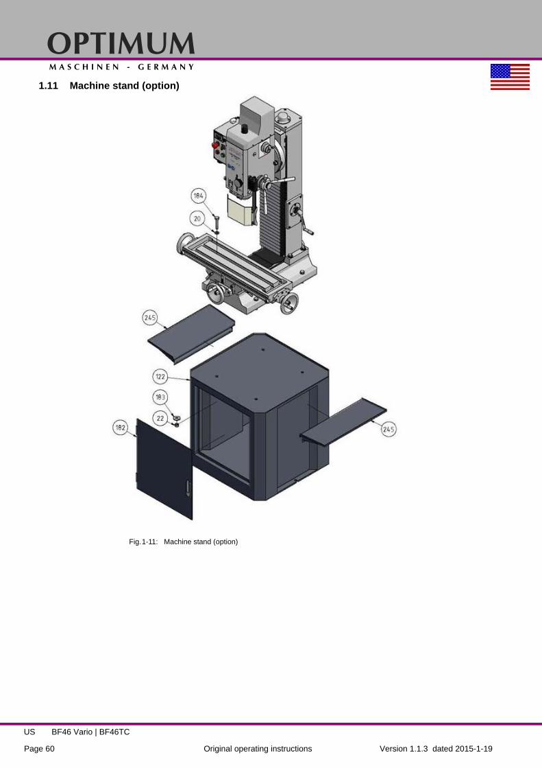
OPTIMUMM A S C H I N E N - G E R M A N Y
Version 1.1.3 dated 2015-1-19Page 60 Original operating instructions
BF46 Vario | BF46TCUS
1.11 Machine stand (option)
Fig.1-11: Machine stand (option)

OPTIMUMM A S C H I N E N - G E R M A N Y
Version 1.1.3 dated 2015-1-19 Page 61Original operating instructions
BF46 Vario | BF46TC US
1.11.1 Spare parts listP
os
.
Description Qty. Drawing no. Size Article no.
1 Connect board 1 1015119 03338453012 Socket head screw 1 ISO 4762 M3 x 103 Digital indicator 1 DQ-02A 03338453035 Hexagon screw 1 DIN 912 M12 x 506 O-ring 1 DIN 3771 77.5 x 5.3 0333845306
7Pinole 1 1015105b 0333845307Pinole 1 1015105
8Taper roller bearing ISO40 1 33209_Q 04033209
Taper roller bearing MT4, option 1 33208_Q
9Spindle R8 1 R8 0333845309y
Spindle ISO 40, option 1 1015101_SK40 SK40 0333845309Spindle MT4, option 1 1015101_MK4 MK4
10 Taper roller bearing 1 33007 0403300711 Set screw 1 DIN 915 M10 x 2512 Hexagon nut 1 DIN 934 M1013 Snap ring 1 DIN 472 80 x 2.5 033384531314 Grooved ball bearing 1 6011-2RZ 0406011.2R15 Clamping nut 1 1015106 033384531516 Hexagon screw 2 DIN 912 M5 x 1217 Support 1 1015103b 033384531718 Hexagon screw 1 DIN 912 M8 x 2019 Set screw 2 DIN 915 M4 x 820 Washer 11 DIN125 A 1621 Lock washer 1 DIN 127 A 16 033384532122 Hexagon nut 7 ISO 4032 M1623 Washer 1 DIN 125-2 1724 Lock washer 7 DIN 128 A16 033384532425 Hexagon screw 1 ISO 4017 M16 x 6026 Pinion shaft 1 1015135 033384532627 Grooved ball bearing 2 6003 0406003.2R28 Oil sight glas 1 033384532829 O-ring 1 DIN 3771 20 x 2.65 - N - NBR 70 033384532930 Hexagon screw 1 AS 2465 3/8 x 1/2 UNC 033384533031 Copper washer 1 10 033384533132 Toothed drive shaft 1 1015107 033384533233 Key 1 DIN 6885 A10 × 6 × 18 033384533334 Snap ring 2 DIN 471 48 033384533435 Gear 55 1 1015108 033384533536 Holder drawin bar 1 1015141 0333845336
37Drawin bar R8 0333845337y
Drawin bar ISO40 1 1015701b M16 0333845337Drawin bar MT4 1 1015701 0333845337MK4
38a Shaft, year of manufacture to 2011 1 1015113 0333845338a38 Shaft, year of manufacture from 2011 1 033384533839 Gear 37T 1 up to year 2006 straight teeth 0333845339A39 Gear 37T 1 from year 2006 helical teeth 033384533940 Key 1 DIN 6885 A 6 x 6 x 10 033384534041 Key 1 DIN 6885 A 6 x 6 x 70 033384534142 Snap ring 1 DIN 471 17 033384534243 Snap ring 1 DIN472 35 033384534344a Gear, year of manufacture up to 2011 1 1015114 0333845344a44 Gear, year of manufacture from 2011 1 033384534445 Key 1 DIN 6885 A 6 x 6 x 16 033384534546 Gear 47 1 1015115 033384534647 Gear 33 1 1015116 033384534748 Snap ring 1 DIN 471 32 033384534849 Milling head housing cover 1 1015109 033384534950 Snap ring 1 DIN 472 55 033384535051 Grooved ball bearing 2 6307.2R 0406307R52 Gear wheel 1 1015117 1015117 033384535253 Motor 1 Motor 2,2 KW 033384535354 Key 1 DIN 6885 A 6 x 6 x 36 033384535455 Snap ring 1 DIN 471 32 x 1.5 033384535556 Grooved ball bearing 1 6308-2RZ 0406308.2R57 Bearing cover 1 1015110 033384535758 Socket head screw 13 ISO 4762 M5 x 1259 Vent screw 1 1015142 033384535960 Socket head screw 6 ISO 4762 M8 x 4061 Cylindrical pin 2 ISO 8734 8 x 50 - A 033384536162 Washer 7 DIN 125 863 Socket head screw 27 ISO 4762 M8 x 25

OPTIMUMM A S C H I N E N - G E R M A N Y
Version 1.1.3 dated 2015-1-19Page 62 Original operating instructions
BF46 Vario | BF46TCUS
64 Clamping bolt 1 1015138 033384536465 Clamping bolt 1 1015139 033384536566 Clamping lever 1 033384536667 Taper gear wheel 35 1 1015133 033384536768 Worm shaft 1 1015129 033384536869 Scale ring 1 1015130 inch 0333845369y70 Knurling tool 1 1015131 033384537071 Spring plate 4 D140-04-09 033384537172 Set screw 1 DIN 916 M6 x 873 Hub 1 1015134 033384537374 Lever 3 033384537474 Lever year of manufacture 05/2009 3 0333843022775 Key 1 DIN 6885 A 8 x 7 x 20 033384537576 Threaded rod 1 1015128-2 033384537677 Compression spring 1 2×14×30-3 2×14×30-3 033384537778 Knurling tool 1 1015128-1 033384537879 Spring pin 1 ISO 13337 3 × 2580 Measuring ruler digital display 1 0333845380
80-1 Protective cover 1 0333845380180-2 Socket head screw !81 Drilling depth stop 1 1015122 033384538182 Threaded rod 1 1015121 033384538283 Knurling tool 1 1015123 033384538384 Spring pin 1 ISO13337 3 × 1485 Driving disk 1 1015136 033384538586 Hexagonal screw with slot 1 ISO 1207 M5 x 1087 Return spring 1 1015137 033384538788 Screw 2 DIN427 M3 × 1089 Return spring housing 1 1015120 033384538990 Disk 1 1015140 033384539091 Socket head screw 1 ISO 4762 M6 x 1092 Choice rotary switch transmission 1 1015132 033384539293 Shaft 1 1015127 033384539394 Set screw 1 DIN 914 M5 x 1695 O-ring 1 DIN 3771 6.9 × 1.8 G 033384539596 Support shift fork 1 1015126 033384539697 O-ring 1 DIN 3771 20 x 3.55 - N - NBR 70 033384539798 Screw 3 ISO 10642 M5 × 1099 Set screw 1 DIN 913 M8 x 8100 Steel ball 1 GB-T308-1994 6.5 03338453100101 Position cover choice rotary switch 1 1015506 03338453101102 Arm shift fork 1 1015125 03338453102103 Set screw 1 DIN 913 M5 x 8104 Shift fork 1 1015124 03338453104105 Snap ring 1 DIN 471 10 × 1 03338453105106 Socket head screw 6 ISO 4762 M4 x 8107 Motor cover 1 1015111 03338453107108 Cover cap 1 DM14-01-09 03338453108109 Hexagon screw 2 ISO 4014 M16 x 65110 Hexagon screw 1 ISO 4014 M16 x 80111 Taper gib 1 1015119 03338453112113 Adjusting screw 6 1015002 03338453113114 Angle scale 1 1015502 03338453114116 Socket head screw 1 ISO 4762 4762-M4 × 8117 Column 1 1015301 03338453117118 Scale 1 1015503 inch 03338453118y120 Machine base 1 1015202 03338453120121 Hexagon screw 4 ISO 4014 M16 x 70122 Machine stand, option 1 1015702 3353005
123Zero point - linear measurement cross
table1 1015204 03338453123
124 Cross table guidance 1 1015210 03338453124125 Socket head screw 28 ISO 4762 M8 x 16126 Spindle nut x-axis 1 1015208 inch 03338453126y127 Socket head screw 2 ISO 4762 M5 x 20128 Grease nipple 8 0340114129 Brass pin 6 03338453129131 Taper gib x-axis 1 1015207 03338453131132 Taper gib y-axis 1 1015215 03338453132134 Milling table 1 1015209 03338453134135 Bearing block x-axis 1 1015219 03338453135136 Cylindrical pin 6 ISO 2338 8 h8 x 35 03338453136137 Bearing block x-axis 1 1015218 03338453137
Po
s. Description Qty. Drawing no. Size Article no.

OPTIMUMM A S C H I N E N - G E R M A N Y
Version 1.1.3 dated 2015-1-19 Page 63Original operating instructions
BF46 Vario | BF46TC US
138 Slots stone end stop x-axis 2 1015206 03338453138139 Bushing end stop x-axis 2 1015205 03338453139140 Spacer ring x-axis 2 1015220 03338453140141 Grooved ball bearing 5 6004 6004 0406004.2R142 Spindle x-axis 1 1015216 inch 03338453142y143 Key 3 DIN 6885 A 6 x 6 x 14 03338453143144 Handwheel 3 1015211 03338453144145 Scale ring 3 1015213 inch 03338453145y146 Clamping nut 3 1015212 03338453146147 Set screw 3 DIN 913 M16 x 20148 Handle complete 4 JB-T7270.4-1994 03338453148
148-1 Bushing 4 033384531481148-2 Screw 4 033384531482
149Screwing in connection coolant drain-
age1 1015217 03338453149
150 Bearing block y-axis 1 1015201 03338453150151 Spindle nut y-axis 1 1015214 inch 03338453151y152 Spindle y-axis 1 1015203 inch 03338453152y153 Bearing block y-axis 1 1015221 03338453153154 Grooved ball bearing 4 6004-2Z 6004-2Z 0406004.2R155 Snap ring 1 DIN 472 45 x 1.75 03338453155156 Spindle cover 2 1015222 03338453156158 Bearing block 1 1015308 03338453158159 Scale x-axis 1 1015504 inch 03338453159y160 Plate 1 03338453160161 Spacer 1 1015302 03338453161162 Taper gear 42 1 1015303 03338453162163 Spacer 1 1015305 03338453163164 Flange 1 1015306 03338453164165 Spindle nut z-axis 1 1015307 03338453165166 Spacer 1 1015310 03338453166167 Shaft 1 1015311 03338453167168 Disk 1 1015312 03338453168169 Bearing block z-axis 1 1015313 03338453169170 Cover plate column 1 1015314 03338453170171 Bearing cover 1 1015315 03338453171172 Spindle nut z-axis 1 1015316 inch 03338453172y173 Spindle nut z-axis 1 1015317 inch 03338453173y174 Socket head screw 4 ISO 4762 M8 x 12175 Key 1 DIN 6885 A 5 x 5 x 20 03338453175176 Key 1 DIN 6885 A 6 x 6 x 20 03338453176177 Socket head screw 8 ISO 4762 M6 x 16178 Snap ring 2 DIN 472 42 x 1.75 03338453178179 Skew-angle roller bearing 1 3204 A 0403204A.2R180 Spindle z - axis 1 1015309 inch 03338453180y181 Groove nut 2 DIN 1804 M16 03338453181182 Door machine stand 1 1015702_1 03338453182183 Washer 4 DIN 9021 17184 Hexagonal screw 4 DIN 6914 M16 x 85185 Switch R/L 1 03338453185186 Potentiometer 1 03338453186
186-1 Knob 1 033384531861187 Push button off 1 03338453187188 Push button on 1 03338453188189 Emergency OFF push button 1 03338453189190 Main switch 1 03338453190
191Socket head screw with countersunk
head 14 ISO 10642 M4 × 6
192 Electric box - cover 1 1015402 03338453192193 Electric box - housing 1 1015401 03338453193194 Electric box - cover 1 BF46-FL223-003 03338453194195 Socket head screw 4 ISO 4762 M3 x 12198 Bellows 1 1015004 03338453198199 Clamping lever 6 03338453199200 Socket head screw 1 ISO 4762 M10 x 16201 Rubber cover 1 03338453201202 Control board 1 03338453700 03021303201203 Strain relief lead switchbox 2 03338453203204 Set screw 2 DIN 913 M6 x 25205 Cylindrical pin 1 ISO 8733 8 x 40206 Housing milling head 1 1015104 03338453206207 Compression spring 1 0.8×5×25-3 03338453207208 Radial rotary shaft seal 1 CR 55x80x8 HMS4 R 03338453208
Po
s. Description Qty. Drawing no. Size Article no.

OPTIMUMM A S C H I N E N - G E R M A N Y
Version 1.1.3 dated 2015-1-19Page 64 Original operating instructions
BF46 Vario | BF46TCUS
209 Zero point - scale 1 B26-02-27 03338453209210 Centerring piece pinole 1 B26-02-04 03338453210211 Center ring scale 1 1015319 03338453211212 Crank 1 B26-01-09 03338453212213 Scale 1 1015318 inch 03338453213y215 Electronic display 1 03338453215214 Electric box - switch plate 1 1015403 03338453214216 Threaded pin 1 M6 x 8 M6 x 8217 Attaching bracket 1 03338453217221 Support 1 03338453221
221-1 Housing 1 033384532211221-2 Steel ball 1 033384532212221-3 Spring plate 1 033384532213221-4 Screw 2 033384532214221-5 Micro switch 1 033384532215221-6 Aluminium profile admission 1 033384532216221-7 Cover 1 033384532217222 Clamping scew 1 03338453222223 Attaching bracket 1 03338453223224 Socket head screw 2 03338453224225 Sensor end position below 1 03338453225
225-1 Sensor end position top 1 033384532251225-2 Rotation speed sensor 1 033384562252226 Nut 4 03338453226227 Socket head screw 2 03338453227228 Socket head screw 1 03338453228229 Aluminium profile 1 03338453229230 Protection 1 03338453230231 Washer 2 03338453231232 Socket head screw 2 03338453232233 indicator drilling depth stop 1 03338453233234 Socket piece milling tool 2 03338453234235 Socket head screw 2 GB 70 - 85 M8 x 16237 Taper gear wheel 21 teeths 1 1015304 03338453236238 Groove nut 2 1015323 03338453238239 Spacer 1 1015322 03338453239240 Bearing cover 1 1015320 03338453240241 Socket head screw 3 GB 70 - 85 M6x25242 Bearing block 1 1015308b 03338453242243 Spacer 1 101531 03338453243245 Chip tray 2 03338453245246 Gear 1 03338453246
247 Holder sensor 1 03338456247248 Drawin bar 1 03338456248250 Plate 1 03338456250251 Washer 1 DIN 125/6252 Hexagon socket screw 3 DIN 4762-M6x25253 Hexagon socket screw 4 DIN 4762-M8x70254 Cover 1 03338456254255 Angle 1 03338456255256 Hexagon socket screw 3 DIN 4762-M5x12257 Washer 3 DIN 125/6258 Button On 1 03352394125259 Switch box 1 03352394123260 Button Off 1 03352394126261 Cover switch box 1 03352394127262 Air tube 4 mm 03338453262263 Air tube 8 mm 03338456263264 Cover 1 03338456264265 Cover 1 03338456265267 Button 2 03338456267268 3-way distributor 1 03338456410269 Plug 2 03338453269270 Adapter 1 03338453270271 Plug 1 03338453271272 Oiler 1 03336020001273 Cover 1 03338456273274 Motor 1 03338456274275 Hexagon socket screw 4 DIN 4762-M6x30276 Washer 4 DIN 125/6277 Hexagon socket screw 4 DIN 4762-M8x25
Po
s. Description Qty. Drawing no. Size Article no.

OPTIMUMM A S C H I N E N - G E R M A N Y
Version 1.1.3 dated 2015-1-19 Page 65Original operating instructions
BF46 Vario | BF46TC US
278 Washer 4 DIN 125/8279 Washer 4 DIN 125/6280 Spring washer 4 DIN 129/6281 Hexagon nut 4 DIN 4032/M6282 Gear box 1 03338456282283 Fitting key 1 DIN 6885/5x5x14284 Endswitch 2 03338456284285 Flange 1 03338456285286 Hexagon socket screw 4 DIN 4762-M8x25287 Grub screw 2 DIN 4026/M5x12288 End stop 1 03338456288289 End stop 2 03338456290 Fitting key 1 DIN 6885/5x5x12291 Shaft 1 03338456291292 Crown gear 1 03338456292293 Spring 1 03338456293294 Crank 1 03338456294295 Sleeve 1 03338456295296 Washer 1 03338453296297 Hexagon socket screw 1 DIN 4762-M5x20298 Cover control box 1 0335239488299 Control box 1 0335239490300 Electric valve 1 0335239492301 T-fiting with quick connector 1 0335239497302 Quick connector 1 03352394122303 Signal lamp 1 03352394114304 Fuse 1 4A 03352394116305 Fuse housing cpl. 1 03338453305306 Maintenance unit 1 03352394138307 Quick connector 2 03352394137308 Air tube 13 mm 03352394135309 Plug 1 03338453309310 Plug 1 03338453310311 Pneumatic cylinder 1 0335239481312 Column BF46TC Vario 1 03338456312313 Holder control panel 1 03338430377
Po
s. Description Qty. Drawing no. Size Article no.

OPTIMUMM A S C H I N E N - G E R M A N Y
Version 1.1.3 dated 2015-1-19Page 66 Original operating instructions
BF46 Vario | BF46TCUS
1.12 Wiring diagram 1 of 2/ BF46, BF46TC
Fig.1-12: Wiring diagram 2 of 2/ BF46, BF46TC

OPTIMUMM A S C H I N E N - G E R M A N Y
Version 1.1.3 dated 2015-1-19 Page 67Original operating instructions
BF46 Vario | BF46TC US
1.13 Wiring diagram 2 of 2/ BF46TC
Fig.1-13: Wiring diagram 2 of 2/ BF46TC

OPTIMUMM A S C H I N E N - G E R M A N Y
Version 1.1.3 dated 2015-1-19Page 68 Original operating instructions
BF46 Vario | BF46TCUS
1.13.1 Parts list electrical components BF46 Vario, BF46TC Vario
Po
s.
Description Qty. Size Article no.
Parts list electrical komponents for BF46 Vario, BF46TC Vario1S0 Main switch 1 LW8GS-20104-2/660V,20A 033384531901A0 Brushlesscontroller 1 030213032011F0 Fuse 1 10A 033384531F01Z0 Line filter 1 033384531Z01B1 Milling chuck safety switch 1 0302024153-41S1 Emergency-Stop button 1 LA103/10A, 660V 033384531891F1 Fuse 1 10A 033384531F01M2 Drive motor 1 03338453531S3 Button On 1 LA103XD-22/36V,10A 033384303861S4 Button Off 1 LA103 033384531871S5 Functional switch 1 Kraus&Naimer/ F89580/001 033384531851B5 Upper end position sensor 1 030213032251B6 Lower end position sensor 1 030213032301R7 Potentiometer 1 WX14-12/4K7 03338120R1.51B8 Speed sensor 1 0333845322521A8 Rotation speed indicator 1 SN100304 03338120P1.3
Parts list electrical components only for BF46TC Vario2S0 Button tool changer 1 SHAN-HO/ 6A, 250V AC 033523941252F0 Fuse 1 4A 033523941162S1 Button tool changer 1 SHAN-HO/ 6A, 250V AC 033523941262H1 Work light 1 24V 033523941142Y1 Solenoid valve 1 Amisco 24V, 5A 03352394922S3 Button feed z-axis 1 LA130/ 400V, 12A 033384532672S4 Button feed z-axis 1 LA130/ 400V, 12A 033384532672B5 Endswitch 1 Delixi 220V/3A 03338453284
2M6 Z-axis feed motor 1220V, 120W, 0,95A,
1350 rpm03338453274
2B6 Endswitch 1 Delixi 220V/3A 033384532842C7 Capacitor 1 7µF/150V 033384562C7

OPTIMUMM A S C H I N E N - G E R M A N Y
Version 1.1.3 dated 2015-1-19 Page 69Original operating instructions
BF46 Vario | BF46TC US
1.14 Lubrication diagram
Fig.1-14: Lubrication diagram
1.14.1 Lubricating unit
Po
s.
Description Qty. Size Article no.
1 Oiler 1 033360200012 L- Connector 8 M10x1 033384564023 Oil tube 4mm 033384564034 Protecting cap 14 033384564045 T- Connector 1 033384564056 L- Connector 2 033384564067 Series connection 2 M10x1 033384564078 Screwing 3 M10x1 033384564089 Series connection 1 03338456409
10 Manifold 1 0333845641011 Connector screw 1 0333845641112 Manifold 1 0333845641213 Tube protection 03338456413

OPTIMUMM A S C H I N E N - G E R M A N Y
Version 1.1.3 dated 2015-1-19Page 70 Original operating instructions
BF46 Vario | BF46TCUS

OPTIM
UM
MA
SC
HI
NE
N
-
GE
RM
AN
Y
1.1.3 2015-01-19
71
Lubricant
Viskosity
ISO VG
DIN 51519 mm²/s (cSt)
Designation according DIN 51502
Gear oil
VG 680 CLP 680 Aral Degol
BG 680 BP Energol GR-XP 680
SPARTAN EP 680
Klüberoil GEM 1-680
Mobilgear 636
Shell Omala 680
Meropa 680
VG 460 CLP 460 Aral Degol
BG 460 BP Energol GR-XP 460
SPARTAN EP 460
Klüberoil GEM 1-460
Mobilgear 634
Shell Omala 460
Meropa 460
VG 320 CLP 320 Aral Degol
BG 320 BP Energol GR-XP 320
SPARTAN EP 320
Klüberoil GEM 1-320
Mobilgear 632
Shell Omala 320
Meropa 320
VG 220 CLP 220 Aral Degol
BG 220 BP Energol GR-XP 220
SPARTAN EP 220
Klüberoil GEM 1-220
Mobilgear 630
Shell Omala 220
Meropa 220
VG 150 CLP 150 Aral Degol
BG 150 BP Energol GR-XP 150
SPARTAN EP 150
Klüberoil GEM 1-150
Mobilgear 629
Shell Omala 150
Meropa 150
VG 100 CLP 100 Aral Degol
BG 100 BP Energol GR-XP 100
SPARTAN EP 100
Klüberoil GEM 1-100
Mobilgear 627
Shell Omala 100
Meropa 100
VG 68 CLP 68 Aral Degol
BG 68 BP Energol GR-XP 68
SPARTAN EP 68
Klüberoil GEM 1-68
Mobilgear 626
Shell Omala 68
Meropa 68
VG 46 CLP 46 Aral Degol
BG 46 BP Bartran
46 NUTO H 46
(HLP 46) Klüberoil
GEM 1-46 Mobil DTE
25 Shell Tellus
S 46 Anubia EP
46
VG 32 Aral Degol
BG 32 BP Bartran
32 NUTO H 32
(HLP 32) LAMORA HLP 32
Mobil DTE 24
Shell Tellus S 32
Anubia EP 32
Gear grease G 00 H-20
Aral FDP 00 (Na-verseift) Aralub MFL 00 (Li-ver-
seift)
BP Energrease
PR-EP 00
FIBRAX EP 370 (Na-ver-
seift)
MICRO-LUBE GB 00
Mobilux EP 004
Shell Alvania GL 00 (Li-verseift)
Marfak 00
Bearing greaseK 3 K-20 (Li-
verseift) Aralub HL 3
BP Energrease
LS 3 BEACON 3
CENTO-PLEX 3
Mobilux 3 Shell Alvania R 3 Alvania
G 3
Multifak Premium 3

OPTIMUMM A S C H I N E N - G E R M A N Y
Version 1.1.3 dated 2015-1-19Page 72 Original operating instructions
BF46 Vario | BF46TCUS
2 Malfunctions
Malfunction Cause / possible effects Solution
The mill drill does not start • Power-on sequence ignored. • "Switching on the mill drill“ on page 30 and "Switching on the mill drill“ on page 35
• Have it checked by authorised per-sonnel.
Tool "burnt". • Incorrect speed.• Chips do not come out of the bore hole• Tool blunt.
Operating without cooling agent.
• Select another rate, feed too high.• Pull out tool more often.
Sharpen or replace tool.• Use cooling agent
Impossible to insert grip cone into the spindle sleeve.
• Remove any dirt, grease or oil from the internal conical surface of the spindle sleeve or the grip cone.
• Clean surfaces wellKeep surfaces free of grease.
It is not possible to push-out the taper.
• Optional MT4 taper is shrinked on the Morse taper.
• Let the machine run at highest speed for two minutes in order to warm it up and then retry to disas-semble the taper.
Motor does not start • Defective fuse. • Have it checked by authorised per-sonnel.
Working spindle rattling on rough piece surfaces
• Climb milling machining not possible under the current operating conditions.
• Clamping lever of the movement axes not tightened.
• Loose collet chuck, loose drill chuck, loose draw-in rod.
• Tool is blunt.• The workpiece is not fastened.• Excessive slack in bearing.
• Working spindle goes up and down.
• Perform conventional milling.
• Tighten clamping lever
• Check, re-tighten.
• Sharpen or replace tool• Clamp the workpiece firmly.• Readjust bearing slack or replace
bearing• Readjust bearing slack or replace
bearing
Fine feed of the spindle sleeve does not work
• Fine feed is not correctly activated.
• Coupling of the fine feed does not cam-in, is soiled, blurred, worn, defective
• "Manual spindle sleeve feed with the fine feed“ on page 41
• Clean, replace.
Digital display • "Malfunctions“ on page 42

OPTIMUMM A S C H I N E N - G E R M A N Y
Version 1.1.3 dated 2015-1-19 Page 73Original operating instructions
BF46 Vario | BF46TC US
3 Appendix
3.1 Copyright
This document is copyright. All derived rights are also reserved, especially those of translation,re-printing, use of figures, broadcast, reproduction by photo-mechanical or similar means andrecording in data processing systems, neither partial nor total.
Subject to technical changes without notice.
3.2 Terminology/Glossary
Term Explanation
Cross table Bearing surface, clamping surface for the workpiece with X- and Y-axis travel
Taper mandrel Cone of the drill or of the drill chuck
Workpiece Piece to be milled, drilled or machined.
Draw-in rod Threaded rod to fix the taper mandrel in the spindle sleeve.
Drill chuck Drill bit chuck
Collet chuck Holder for end mill
Drill-Mill head Upper part of the mill drill
Spindle sleeve Hollow shaft in which the milling spindle turns.
Milling spindle Shaft activated by the motor
Drilling table Supporting surface, clamping surface
Taper mandrel Cone of the drill or of the drill chuck
Spindle sleeve lever Manual operation for the drill feed
Quick action - drill chuck
Drill chuck can be fixed by hand.
Workpiece Piece to be drilled or machined.
Tool Milling cutter, drill bit, etc.
OPTIMUMM A S C H I N E N - G E R M A N Y
Version 1.1.3 dated 2015-1-19Page 74 Original operating instructions
BF46 Vario | BF46TCUS
3.3 LIMITED WARRANTY
OPTIMUM ONE-YEAR LIMITED WARRANTY. OPTIMUM, MODELS COVERED IN THISMANUAL, ARE WARRANTED BY OPTIMUM TO THE ORIGINAL USER AGAINST DEFECTSIN WORKMANSHIP OR MATERIALS UNDER NORMAL USE FOR ONE YEAR AFTER DATEOF PURCHASE. ANY PART WHICH IS DETERMINED TO BE DEFECTIVE IN MATERIAL ORWORKMANSHIP AND RETURNED TO AN AUTHORIZED SERVICE LOCATION, ASOPTIMUM DESIGNATES, SHIPPING COSTS PREPAID, WILL BE, AS THE EXCLUSIVEREMEDY, REPAIRED OR REPLACED AT OPTIMUM OPTION. FOR LIMITED WARRANTYCLAIM PROCEDURES, SEE "PROMPT DISPOSITION" BELOW. THIS LIMITED WARRANTYGIVES PURCHASERS SPECIFIC LEGAL RIGHTS WHICH VARY FROM JURISDICTION TOJURISDICTION.
LIMITATION OF LIABILITY. TO THE EXTENT ALLOWABLE UNDER APPLICABLE LAW,OPTIMUM LIABILITY FOR CONSEQUENTIAL AND INCIDENTAL DAMAGES IS EXPRESSLYDISCLAIMED. OPTIMUM LIABILITY IN ALL EVENTS IS LIMITED TO AND SHALL NOTEXCEED THE PURCHASE PRICE PAID.
WARRANTY DISCLAIMER. A DILIGENT EFFORT HAS BEEN MADE TO PROVIDEPRODUCT INFORMATION AND ILLUSTRATE THE PRODUCTS IN THIS LITERATUREACCURATELY; HOWEVER, SUCH INFORMATION AND ILLUSTRATIONS ARE FOR THESOLE PURPOSE OF IDENTIFICATION, AND DO NOT EXPRESS OR IMPLY A WARRANTYTHAT THE PRODUCTS ARE MERCHANTABLE, OR FIT FOR A PARTICULAR PURPOSE,OR THAT THE PRODUCTS WILL NECESSARILY CONFORM TO THE ILLUSTRATIONS ORDESCRIPTIONS. EXCEPT AS PROVIDED BELOW, NO WARRANTY OR AFFIRMATION OFFACT, EXPRESSED OR IMPLIED, OTHER THAN AS STATED IN THE "LIMITEDWARRANTY" ABOVE IS MADE OR AUTHORIZED BY OPTIMUM.
Technical Advice and Recommendations, Disclaimer. Notwithstanding any past practice ordealings or trade custom, sales shall not include the furnishing of technical advice or assistanceor system design. OPTIMUM assumes no obligations or liability on account of any unauthorizedrecommendations, opinions or advice as to the choice, installation or use of products.
Product Suitability. Many jurisdictions have codes and regulations governing sales,construction, installation, and/or use of products for certain purposes, which may vary fromthose in neighboring areas. While attempts are made to assure that OPTIMUM products complywith such codes, OPTIMUM cannot guarantee compliance, and cannot be responsible for howthe product is installed or used. Before purchase and use of a product, review the productapplications, and all applicable national and local codes and regulations, and be sure that theproduct, installation, and use will comply with them.
Certain aspects of disclaimers are not applicable to consumer products; e.g., (a) somejurisdictions do not allow the exclusion or limitation of incidental or consequential damages, sothe above limitation or exclusion may not apply to you; (b) also, some jurisdictions do not allow alimitation on how long an implied warranty lasts, consequently the above limitation may notapply to you; and (c) by law, during the period of this Limited Warranty, any implied warranties ofimplied merchantability or fitness for a particular purpose applicable to consumer productspurchased by consumers, may not be excluded or otherwise disclaimed.
Prompt Disposition. A good faith effort will be made for prompt correction or other adjustmentwith respect to any product which proves to be defective within limited warranty. For any productbelieved to be defective within limited warranty, first write or call dealer from whom the productwas purchased. Dealer will give additional directions. If unable to resolve satisfactorily, write toOPTIMUM at address below, giving dealer's name, address, date, and number of dealer'sinvoice, and describing the nature of the defect. Title and risk of loss pass to buyer on delivery tocommon carrier. If product was damaged in transit to you, file claim with carrier. Manufactured for OPTIMUM, LDS Industries, LLC, 930 W. National Ave. Addison, IL 60101, Tel.: 1-630-785-6437

OPTIMUMM A S C H I N E N - G E R M A N Y
Version 1.1.3 2015-1-19 75Original operating instructions
BF46 Vario | BF46TC GB
EC - Declaration of Conformity
Machinery Directive 2006/42/EC Annex II 1.A
The manufacturer / retailer:
Optimum Maschinen Germany GmbHDr.-Robert-Pfleger-Str. 26D- 96103 Hallstadt
hereby declares that the following product,
Type of machine: Drilling-milling machine
Type designation: BF46V ; BF46TC
Serial number: _ __ __ __ __
Year of manufacture: 20__
Manual geared drill with with frequency converter for speed control for private persons as well as for craftand industrial plants which meets all the relevant provisions of the above mentioned Directive 2006/42/ECas well as the other directives applied (below) including their amendments in force at the time of declara-tion. The following other EU Directives have been applied: EMC Directive 2014/30/EC, Low Voltage Direc-tive 2014/35/EC
The safety objective meet the requirement of EC Directive 2006/95/EC
The following harmonized standards were applied:
EN 1037:1995+A1:2008 Safety of machinery - Prevention of unexpected start-up
EN ISO 14119 Safety of machinery - Interlocking devices associated with guards - Principles for design andselection
EN 61800-5-1 Adjustable speed electrical power drive systems 2008-04 + correction 2
EN 61800-3:2012-09 Adjustable speed electrical power drive systems + correction 1
EN 13128:2001+A2:2009/AC:2010 Safety of machine tools - Milling machines (including boring machines)
EN 50581:2012 Technical documentation for the assessment of electrical and electronic products withrespect to the restriction of hazardous substances
EN 60204-1:2006/AC: 2010 Safety of machinery - Electrical equipment of machines - Part 1: Generalrequirements (IEC 60204-1:2005 (modified))
DIN EN 55011 class A: 2003-08 Industrial, scientific radio-frequency equipment
EN ISO 12100:2010 Safety of machinery - General principles for design - Risk assessment and risk reduc-tion (ISO 12100:2010)
EN ISO 13857:2008 Safety of machinery - Safety distances to prevent hazard zones being reached byupper and lower limbs
Responsible for documentation: Kilian Stürmer, phone: +49 (0) 951 96555 - 800
Address: Dr.-Robert-Pfleger-Str.26D - 96103 Hallstadt
Hallstadt, 2015-01-16Kilian Stürmer(CEO, General manager)

OPTIMUMM A S C H I N E N - G E R M A N Y
Version 1.1.3 dated 2015-1-19Page 76 Original operating instructions
BF46 Vario | BF46TCUS
Index
AAssembling ........................................................... 21Available accesories ............................................ 27CChange information .............................................. 74Changing the speed range ................................... 40Clamping a tool
BF46TC ........................................................... 37BF46V ............................................................. 31
Cleaning and lubricating ....................................... 25Commissioning ..................................................... 25Control and indicating elements
BF46TC ........................................................... 33BF46V ............................................................. 28
Copyright .............................................................. 73DDrilling-milling capacity ......................................... 17EEC - declaration of conformity .............................. 75Electrical connection ............................................ 17Environmental conditions ..................................... 18FFilling in gear oil ................................................... 26Fine feed .............................................................. 41First commissioning ............................................. 25LLifting equipment .................................................. 15Load suspension point ......................................... 21MMain switch .......................................................... 13Malfunctions ......................................................... 72Misuse .................................................................... 8OOptional accessories ............................................ 27PPower supply ........................................................ 25Protective
equipment ....................................................... 14Protective cover ................................................... 13QQualification of the staff
Safety .............................................................. 10SSafety instructions .................................................. 6Scope of delivery .................................................. 19Separating protective equipment ......................... 13Speed range ......................................................... 40Speeds ................................................................. 18Spindle seat ......................................................... 17Spindle sleeve lever ............................................. 43Storage and packaging ........................................ 20Switch on ........................................................ 30, 35Switching on the machine .............................. 30, 35
Swivelling the drill-mill head ..................................43TTechnical data
Electrical connection ........................................17Emissions ........................................................18Environmental conditions .................................18Speeds .............................................................18Spindle seat .....................................................17
Technical DetailsDrilling-milling capacity ....................................17Working area ...................................................17
Threading ..............................................................32WWarming up the machine ......................................26Working area ........................................................17


![[Metalworking] Machining](https://img.pdfslide.us/doc/110x75/577d2e641a28ab4e1eaee711/metalworking-machining.jpg)