Embed Size (px)
Citation preview
12/30/2011
8:2
7:2
8
AM
RE
VISIO
N
C:\
d\projects\standards\structures\current\ready4rele
ase\2012book_draft\20502-1of1.d
gn
NO.
SHEET
NO.
INDEX
rd960rh
DESCRIPTION:
REVISION
LAST
FY 2012/2013
FDOT DESIGN STANDARDS
Showing Double Bearing
Half Elevation
Showing Single Bearing
Half Elevation
(Top of Substructure)
Level Bearing Seat
(See Plans)
Varies
D
D/2
Bearing Pad
Elastomeric
Composite
(See Plans)
Varies ~ 1" Min.
D
5"5"
(Typ.)
See Detail "A"spacing
Anchor Stud 5" 3 Equal spaces
Bottom of Beam
Cross Slope
�
(See Note 4)
Seal weld Cap to top of plate "A" (Typ.)
with Galvanized Caps (16 Ga. Min.);
Flat Headed Machine Screws
" dia. Electro-plated, Countersunk�
"b2"b2 "b2
K2
J
1"
Composite Elastomeric Bearing Pad
Beveled Bearing Plate B
K1
J
1"
Substructure)
Seat (Top of
Level Bearing
2"
weldin
g)
2" (after
2"
DC +
Bottom of Beam
2"
C +D
2"
"b2
sin Ø sin Ø
sin Ø
sin Øâ�� Beâ�� Besin Ø
sin Ø
sin Øsin Ø
"b2
"bD x Varies x
Bearing Plate A
Embedded
"b
sin Ø
2 tan Ø
or � Pier or
Front Face of Backwall
"bD x Varies x
Bearing Plate A
Embedded
or � Pier or
Front Face of Backwall
2 tan Ø
sin Ø
Edge of Bottom Flange (Typ.)
Bearing Pad
Elastomeric
Composite
or Bent
Backwall or �
Front Face of
â�� Beam & â�
� Bearing
� Be 2"
1"
K1
90°
or less
Skew 15°
J
DC +
tan Ø
Ø
"b2
C
(Typ.) (See Note 8)
" Min.)b(D x Varies x
Beveled Plate B
") &b(D x Varies x
~ Embedded Plate A
Bearing Plates A & B
(See Pla
ns)
Varie
s
5"
2"
"b
2
D
3 E
qual spaces
2 E
qual spaces
5"
(See Pla
ns)
Varie
s
Florida U-Beam (Typ.)
Face of Pier or Bent Cap
2" "b
2
(See Plans)
Varies ~ 1" Min.
2" Equal Spacing
C
5"
"b
2
ED
5"
5"
"b
2
�
"b
2
or less
Skew 15°
90°
1"
2"
K2J
90°
C
�
Ø
"b2
C + D/tan Ø
Ø
D
5"
(See Plans)
Varies ~ 1" Min.
2" Equal Spacing
or Bent Cap
Face of Pier
"b
2
90°
1"
2"
"b2
Ø
�
� Be
C + D/tan Ø
Pad (Typ.)
� Be
(Typ.)
End of Beam
(Typ.)
Bearing Pad
Elastomeric
Composite
Pier or Bent
Backwall or
Front Face of
(Positive Cross Slope shown, Negative Cross Slope similar)
END ELEVATION(See Note 7)
SIDE ELEVATION
DETAIL "A"
PLAN VIEW OF TYPICAL SINGLE BEARING PLAN VIEW OF TYPICAL DOUBLE BEARING
(O° < Skew = 15° shown, Skew = 0° Similar)
PLAN
2 Eq. sp.
2 Eq. sp.
Anchor Stud
Headed Concrete
b" Dia. End Welded,
See Detail "A"
Anchor Studs,
â�� ˘�" Dia.
2 Equal sp.
(Typ.)
Screws
˘�"
� Hole
Studs (Typ.)
x 2˘�" An
â�� ˘�
2 Equal sp.
(See Note No. 3)
˘�" Dia. Scr
� Hole
Direction of Stationing
Direction of Stationing
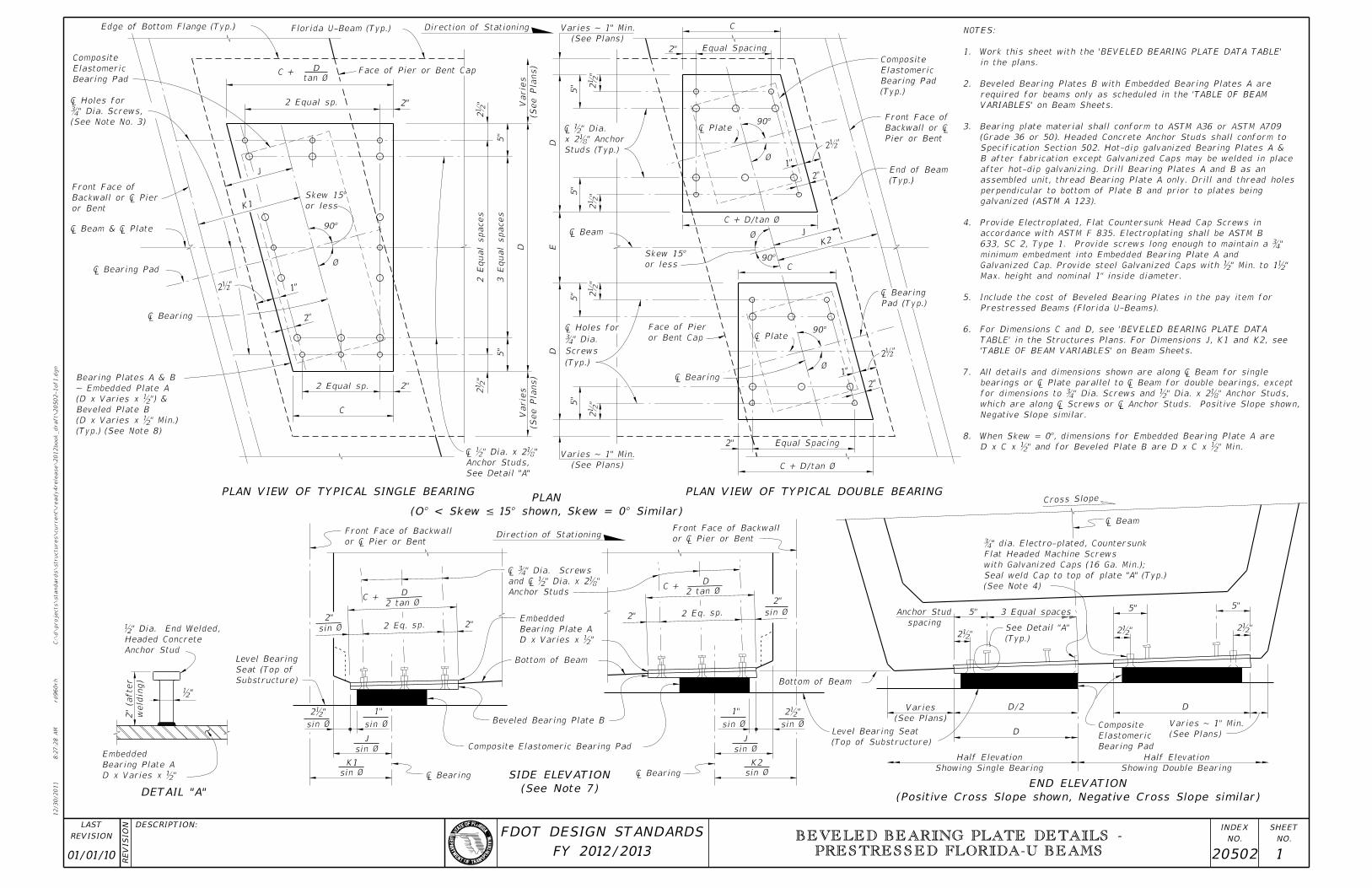
D x C x b" and for Beveled Plate B are D x C x b" Min.
8. When Skew = 0°, dimensions for Embedded Bearing Plate A are
Negative Slope similar.
 which are along � Screws or � Anchor Studs. Positive Slope
 for dimensions to ˘�" Dia. Screws and ˘�" Dia. x 2˘�" Anchor
 bearings or � Plate parallel to � Beam for double bearings,
7. All details and dimensions shown are along � Beam for s
’TABLE OF BEAM VARIABLES’ on Beam Sheets.
TABLE’ in the Structures Plans. For Dimensions J, K1 and K2, see
6. For Dimensions C and D, see ’BEVELED BEARING PLATE DATA
Prestressed Beams (Florida U-Beams).
5. Include the cost of Beveled Bearing Plates in the pay item for
Max. height and nominal 1" inside diameter.
Galvanized Cap. Provide steel Galvanized Caps with b" Min. to 1b"
minimum embedment into Embedded Bearing Plate A and
 633, SC 2, Type 1. Provide screws long enough to maintain a
accordance with ASTM F 835. Electroplating shall be ASTM B
4. Provide Electroplated, Flat Countersunk Head Cap Screws in
galvanized (ASTM A 123).
perpendicular to bottom of Plate B and prior to plates being
assembled unit, thread Bearing Plate A only. Drill and thread holes
after hot-dip galvanizing. Drill Bearing Plates A and B as an
B after fabrication except Galvanized Caps may be welded in place
Specification Section 502. Hot-dip galvanized Bearing Plates A &
(Grade 36 or 50). Headed Concrete Anchor Studs shall conform to
3. Bearing plate material shall conform to ASTM A36 or ASTM A709
VARIABLES’ on Beam Sheets.
required for beams only as scheduled in the ’TABLE OF BEAM
2. Beveled Bearing Plates B with Embedded Bearing Plates A are
in the plans.
1. Work this sheet with the ’BEVELED BEARING PLATE DATA TABLE’
NOTES:
Anchor Studs
and â�� ˘�" Dia.
â�� ˘�" Dia. S
01/01/10 20502 1
BEVELED BEARING PLATE DETAILS -
PRESTRESSED FLORIDA-U BEAMS
12/30/2011
8:2
7:2
9
AM
RE
VISIO
N
C:\
d\projects\standards\structures\current\ready4rele
ase\2012book_draft\20510-1of1.d
gn
NO.
SHEET
NO.
INDEX
rd960rh
DESCRIPTION:
REVISION
LAST
FY 2012/2013
FDOT DESIGN STANDARDS
(G=150psi)
K
(G=150psi)
J
(G=150psi)
H
10"
10"
DCWL
8"
10"
10"
10"(G=150psi)
G
(G=110psi)
F
(G=110psi)
E
(G=110psi)
D
(See Note 1)
PAD TYPE
DIMENSIONS
BEARING PLATE
*BEVELED
DIMENSIONS
BEARING PAD
(Typ.)
4"
**
Prestressed Beam
Bottom Flange of
or Pier Cap
Face of Bent
Bearing Pad
Elastomeric
Composite
90°
Skew > 0°
2" Min. (Skew = 15°)
4" Min. (Skew < 15°)
� Bearin
� B
� Be
ï »¿â �� Bearin
Bearing Pad
Elastomeric
Composite
(Typ.)
Varies
90°
Skew > 0°Varies
or Pier Cap
Face of BentPrestressed Beam
Bottom Flange of
4" Min. (Typ.)
Ø
�� Bearin "b2
� Bearin
� Bearin
Face of Bent or Pier Cap
Prestressed Beam
Bottom Flange of
4" Min.
(Typ.)
90°
Bearing Pad
Elastomeric
Composite
� Bearin
� Bearin
� Beam & � Bear
Pad
� Bea
Layer (Typ.)
(Typ.)
Cover (Typ.)
See Detail "C"
" Elastomer Cover�
required)
Layer (Typ.) (2 layers
" Internal Elastomerb
Layer (Typ.)
(Typ.)
Cover (Typ.)
See Detail "C"
" Elastomer Cover�
required)
Layer (Typ.) (3 layers
" Internal Elastomerb
See Detail "C"Layer (Typ.)
(Typ.)
L or W
Cover (Typ.)
See Detail "C"Layer (Typ.)
(Typ.)
Cover (Typ.)
" Elastomer Cover�
"�
" Elastomer�
required)
Layer (Typ.) (4 layers
" Internal Elastomerb
"�
3
" Elastomer Cover�
required)
Layer (Typ.) (5 layers
" Internal Elastomerb
DETAIL "C"
TYPICAL SECTION TYPE J & K PAD
TYPICAL SECTION TYPE H PAD
TYPICAL SECTION TYPE F & G PAD
TYPICAL SECTION TYPE D & E PAD
PLAN
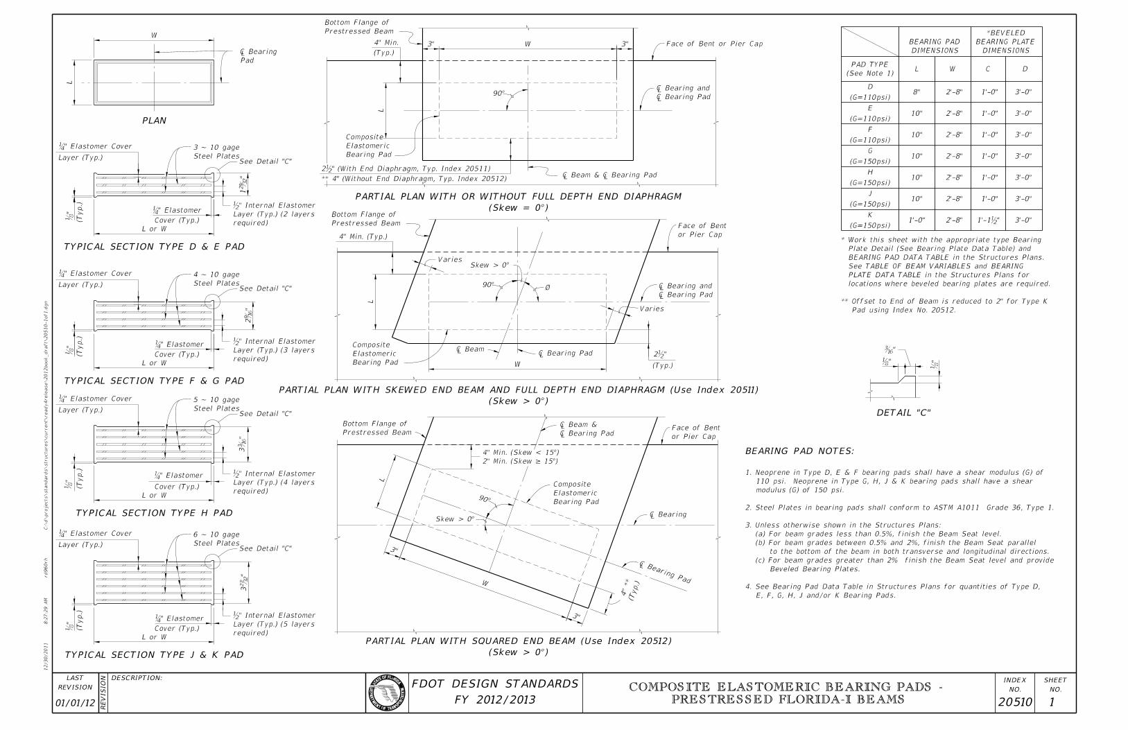
BEARING PAD NOTES:
W
L�
»
L or W
˘�" Elast
ï»
¿
�»
L or W
˘�" Elast
ï»
¿
�»�»
�»
L
3"
3"
W
W
L
3" W 3"
L
L or W
˘�" Elast
�»
ï»
¿
E, F, G, H, J and/or K Bearing Pads.
4. See Bearing Pad Data Table in Structures Plans for quantities of Type D,
Beveled Bearing Plates.
(c) For beam grades greater than 2% finish the Beam Seat level and provide
to the bottom of the beam in both transverse and longitudinal directions.
(b) For beam grades between 0.5% and 2%, finish the Beam Seat parallel
(a) For beam grades less than 0.5%, finish the Beam Seat level.
3. Unless otherwise shown in the Structures Plans:
2. Steel Plates in bearing pads shall conform to ASTM A1011 Grade 36, Type 1.
modulus (G) of 150 psi.
110 psi. Neoprene in Type G, H, J & K bearing pads shall have a shear
1. Neoprene in Type D, E & F bearing pads shall have a shear modulus (G) of
Steel Plates
3 ~ 10 gage
Steel Plates
4 ~ 10 gage
Steel Plates
5 ~ 10 gage
Steel Plates
6 ~ 10 gage
Pad using Index No. 20512.
** Offset to End of Beam is reduced to 2" for Type K
locations where beveled bearing plates are required.
PLATE DATA TABLE in the Structures Plans for
See TABLE OF BEAM VARIABLES and BEARING
BEARING PAD DATA TABLE in the Structures Plans.
Plate Detail (See Bearing Plate Data Table) and
* Work this sheet with the appropriate type Bearing
(Skew > 0°)
PARTIAL PLAN WITH SKEWED END BEAM AND FULL DEPTH END DIAPHRAGM (Use Index 20511)
(Skew > 0°)
PARTIAL PLAN WITH SQUARED END BEAM (Use Index 20512)
** 4" (Without End Diaphragm, Typ. Index 20512)
2b" (With End Diaphragm, Typ. Index 20511)
(Skew = 0°)
PARTIAL PLAN WITH OR WITHOUT FULL DEPTH END DIAPHRAGM
1’-0"
2’-8"
2’-8"
2’-8"
2’-8"
2’-8"
2’-8"
2’-8"
1’-0"
1’-0"
1’-0"
1’-0"
1’-0"
1’-0"
1’-1‰"
3’-0"
3’-0"
3’-0"
3’-0"
3’-0"
3’-0"
3’-0"
01/01/12 20510 1
COMPOSITE ELASTOMERIC BEARING PADS -
PRESTRESSED FLORIDA-I BEAMS
12/30/2011
8:3
1:2
0
AM
RE
VISIO
N
C:\
d\projects\standards\structures\current\ready4rele
ase\2012book_draft\20511-1of2.d
gn
NO.
SHEET
NO.
INDEX
rd960rh
DESCRIPTION:
REVISION
LAST
FY 2012/2013
FDOT DESIGN STANDARDS
WITH BEVELED BEARING PLATE
END ELEVATIONDETAIL "A"
(0° < Skew = 45° shown, Skew = 0° Similar)
PLAN
� P
� Be
1"D/2
D
D/21"
(Typ.)
See Detail "A"
(Top of Substructure)
Level Bearing Seat
Bottom of Beam
weldin
g)
2" (after
"21
sin Øsin Ø
(Varie
s for ske
w > 0°)
" Min. at corners
21
� Beam & �
� Bearing
or � Pier or
Front Face of Backwall
2" � Be
� Be
Face of Pier or Bent Cap
Studs, See Detail "A"
" Anchor81
" dia. x 221
�»
Screws, (See Note No. 3)
" dia.43
� Holes
K1
J
3 Eq.
sp.
"211
"211
90°
Skew > 0°
Ø
"211
"211
K2
J
Ø
Skew > 0°
90°
(Typ.)
Beam
End of
Pad
� Bea
Bearing Pad
Elastomeric
Composite
5"
1"
D
"2
12
"2
12
5"
1"
Pier or Bent
Backwall or
Front Face of
E
" x G x F21
Bearing Plate A
Embedded
C
F F
(Slopes > 2% along � Beam) (See No
WITH BEVELED BEARING PLATES
SIDE ELEVATION
Composite Elastomeric Bearing Pad
(See Note 9)
Slope
Bottom of Beam
or � Pier or
Front Face of Backwall
or � Pier or
Front Face of Backwall
"21
1
sin Ø sin Ø
"21
1
sin Øsin Ø
"21
1
" x G x F21
Bearing Plate A
Embedded
J
sin Ø
K1
sin Ø
"211
3 Eq.
sp.
"211
C
3 Eq. sp.
"21
1
sin Øsin Ø
J
sin Ø
sin Ø
Substructure)
Seat (Top of
Level Bearing
G
Varies
Slope
sin Ø
"21
1
sin Øsin Ø
sin Ø
"21
1"2
11
sin Ø3 Eq. sp.
G
Direction of Stationing
Direction of Stationing
Direction of Stationing
"21
7 "21
7
5" 5"
K2
Negative Slope similar)
(Positive Slope shown;
(Along �
BEVELED BEARING PLATE B
(See Note 8)
" Min. x E x F) (Typ.)21
Plate B (
" x G x F) & Beveled21
Plate A (
Bearing Plates A & B ~ Embedded
Required when E = G (Pad Type K)
(Pad Type K)
when E = G
Required
(Pad Type K)
when E = G
Required
(Pad Type K)
when E = G
Required
End 1 End 2
sin Ø
" when E = G (Pad Type K)21*
*** when E = G (Pad Type K)
** when E = G (Pad Type K)"2
1
" Dia. Screws�
" Dia. Holes for ��»
Anchor Stud
Headed Concrete
" Dia. End Welded, 21
" Dia. Screws43�»
Anchor Studs
"81" Dia. x 22
1�»
(Typ.) (See Note 4)
Seal weld Cap to top of Plate A
Galvanized Caps (16 Ga. Min.);
Flat Headed Machine Screws with
" Dia. Electro-plated, Countersunk43
G (Embedded Plate A)
E (Beveled Plate B)
G (Embedded Plate A)
E (Beveled Plate B)
G (Embedded Plate A)G (Embedded Plate A)
E (Beveled Plate B)E (Beveled Plate B)
Embedded Plate A (Typ.)
Clip acute corner of
Bottom Flange (Typ.)
Edge of FIB
� Be � Be Bearing Pad
Elastomeric
Composite
Beveled Bearing Plate B
(End 1)
(End 2)
(End 1) ***
(End 2) ***
"211
"213
"213
"211
1" ** 1" **
E
E
1" *
1" *
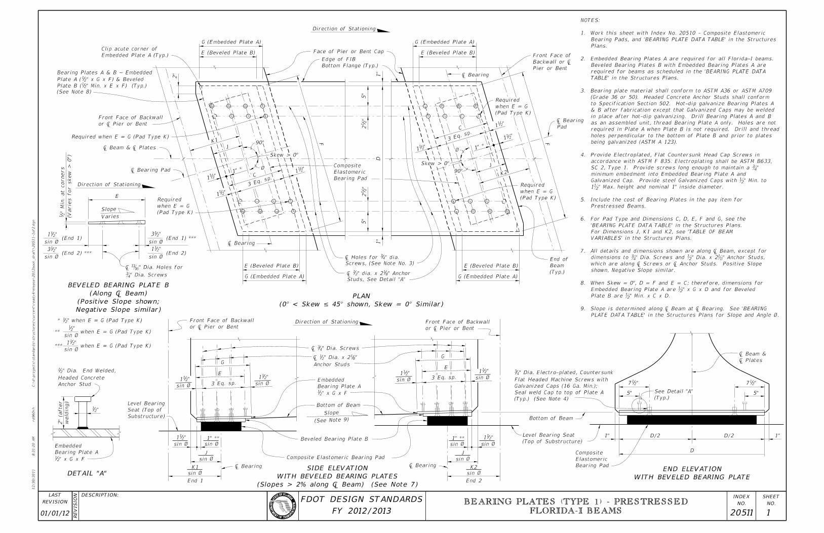
PLATE DATA TABLE’ in the Structures Plans for Slope and Angle Ø.
9. Slope is determined along â�� Beam at â�� Bearing. See ’
" Min. x C x D.b Plate B are
" x G x D and for Beveledb Embedded Bearing Plate A are
8. When Skew = 0°, D = F and E = C; therefore, dimensions for
shown, Negative Slope similar.
 which are along � Screws or � Anchor Studs. Positiv
" Dia. Screws and ˘�" Dia. x 2˘�" Anchor S� dimensions to
7. All details and dimensions shown are along � Beam, excep
VARIABLES’ in the Structures Plans.
For Dimensions J, K1 and K2, see ’TABLE OF BEAM
’BEARING PLATE DATA TABLE’ in the Structures Plans.
6. For Pad Type and Dimensions C, D, E, F and G, see the
Prestressed Beams.
5. Include the cost of Bearing Plates in the pay item for
" Max. height and nominal 1" inside diameter.b 1
Galvanized Cap. Provide steel Galvanized Caps with b" Min. to
minimum embedment into Embedded Bearing Plate A and
 SC 2, Type 1. Provide screws long enough to maintain a
accordance with ASTM F 835. Electroplating shall be ASTM B633,
4. Provide Electroplated, Flat Countersunk Head Cap Screws in
being galvanized (ASTM A 123).
holes perpendicular to the bottom of Plate B and prior to plates
required in Plate A when Plate B is not required. Drill and thread
as an assembled unit, thread Bearing Plate A only. Holes are not
in place after hot-dip galvanizing. Drill Bearing Plates A and B
& B after fabrication except that Galvanized Caps may be welded
to Specification Section 502. Hot-dip galvanize Bearing Plates A
(Grade 36 or 50). Headed Concrete Anchor Studs shall conform
3. Bearing plate material shall conform to ASTM A36 or ASTM A709
TABLE’ in the Structures Plans.
required for beams as scheduled in the ’BEARING PLATE DATA
Beveled Bearing Plates B with Embedded Bearing Plates A are
2. Embedded Bearing Plates A are required for all Florida-I beams.
Plans.
Bearing Pads, and ’BEARING PLATE DATA TABLE’ in the Structures
1. Work this sheet with Index No. 20510 - Composite Elastomeric
NOTES:
01/01/12 20511 1
BEARING PLATES (TYPE 1) - PRESTRESSED
FLORIDA-I BEAMS

12/30/2011
8:2
7:3
1
AM
RE
VISIO
N
C:\
d\projects\standards\structures\current\ready4rele
ase\2012book_draft\20511-2of2.d
gn
NO.
SHEET
NO.
INDEX
rd960rh
DESCRIPTION:
REVISION
LAST
FY 2012/2013
FDOT DESIGN STANDARDS
(Typ.)
See Detail "A"
1"D/2
D
D/21"(Top of Substructure)
Level Bearing Seat
Bottom of Beam
WITHOUT BEVELED BEARING PLATE
END ELEVATION
or � Pier or
Front Face of Backwall
or � Pier or
Front Face of Backwall
or � Pier or
Front Face of Backwall
(See Note 9)
Slope
(See Note 9)
Slope
Bottom of Beam
Bottom of Beam
Composite Elastomeric Bearing Pad
Composite Elastomeric Bearing Pad
See Structures Plans
(Top of Substructure)
Sloped Bearing Seat
See Structures Plans
(Top of Substructure)
Sloped Bearing Seat
(Slopes â�⁄ 0.5% along â�� Beam) (See
WITHOUT BEVELED BEARING PLATES
SIDE ELEVATION
(0.5% < Slopes â�⁄ 2% along â�� Beam) (See
WITHOUT BEVELED BEARING PLATES
SIDE ELEVATION
� P
� Be
"21
1
sin Ø sin Ø
J
sin Ø
K1
sin Ø
or � Pier or
Front Face of Backwall
Substructure)
Seat (Top of
Level Bearing
sin Ø
"21
1
sin Ø
J
sin Ø
sin Ø
"21
1
sin Ø sin Ø
J
sin Ø
K1
sin Ø
sin Ø
"21
1
sin Ø
J
sin Ø
sin Ø
Direction of Stationing
Direction of Stationing
" x G x F21
Bearing Plate A
Embedded
" x G x F21
Bearing Plate A
Embedded
K2
5" 5"
K2
sin Ø
"21
** for Pad Type K
"21
1
sin Ø
G
3 Eq. sp.sin Ø
"21
1
"21
1
sin Ø
G
3 Eq. sp.sin Ø
"21
1
"21
1
sin Ø
G
3 Eq. sp.sin Ø
"21
1"2
11
sin Ø
G
3 Eq. sp.sin Ø
"21
1
Anchor Studs
"81" Dia. x 22
1�»
Anchor Studs
"81" Dia. x 22
1�»
1" **
1" **
1" **
1" **
� Be� Be
� Be� Be Bearing Pad
Elastomeric
Composite
01/01/12 20511 2
BEARING PLATES (TYPE 1) - PRESTRESSED
FLORIDA-I BEAMS
12/30/2011
8:2
7:3
2
AM
RE
VISIO
N
C:\
d\projects\standards\structures\current\ready4rele
ase\2012book_draft\20512-1of2.d
gn
NO.
SHEET
NO.
INDEX
rd960rh
DESCRIPTION:
REVISION
LAST
FY 2012/2013
FDOT DESIGN STANDARDS
WITH BEVELED BEARING PLATE
END ELEVATIONDETAIL "A"
� P
� Be
1"1"
(Typ.)
See Detail "A"
(Top of Substructure)
Level Bearing Seat
Bottom of Beam
weldin
g)
2" (after
"21
C
(Slopes > 2% along � Beam) (See No
WITH BEVELED BEARING PLATES
SIDE ELEVATION
Composite Elastomeric Bearing Pad
Bottom of Beam
or � Pier or
Front Face of Backwall
or � Pier or
Front Face of Backwall
C
J
K1
3 Eq. sp.
J
Substructure)
Seat (Top of
Level Bearing
Varies
Slope
C
3 Eq. sp.
Direction of Stationing
Direction of Stationing
"21
7 "21
7
5" 5"
K2
Negative Slope similar)
(Positive Slope shown;
(Along �
BEVELED BEARING PLATE B
End 1 End 2
" Dia. Screws�
" Dia. Holes for ��»
Anchor Stud
Headed Concrete
" Dia. End Welded, 21
" Dia. Screws43�»
Anchor Studs
"81" Dia. x 22
1�»
(Typ.) (See Note 4)
Seal weld Cap to top of Plate A
Galvanized Caps (16 Ga. Min.);
Flat Headed Machine Screws with
" Dia. Electro-plated, Countersunk43
Bearing Pad
Elastomeric
Composite
� Be � Be
1’-6" 1’-6"
3’-0"
" *‰22‰" *1‰"
1‰"1‰"
1‰"1‰"
1‰"
1’-1‰"
1’-1‰"
(See Note 8)
Slope
‰" x 1’-1‰" x 3’-0"
Bearing Plate A
Embedded
‰" x 1’-1‰" x 3’-0"
Bearing Plate A
Embedded
*** 1‰" when C = 1’-1‰" (Pad Type K)
** 0" when C = 1’-1‰" (Pad Type K)
* ‰" when C = 1’-1‰" (Pad Type K)
1‰" (End 1)
1‰" (End 2)
3‰" (End 1) ***
3‰" (End 2) ***
" Min. at corners
‰
Plate A)
1’-1‰" (Embedded
Plate B)
C (Beveled
90°
3 Eq. sp. "211"2
11
1‰" **
� Be
K1
J
90°
90°
J
K2
"2113 Eq. sp."2
11
� Be
Plate A)
1’-1‰" (Embedded
Plate B)
C (Beveled 1‰" **
Direction of Stationing
Plate A)
1’-1‰" (Embedded
Plate A)
1’-1‰" (Embedded
Plate B)
C (Beveled
Plate B)
C (Beveled1‰" ** 1‰" **
1"
3’-
0"
5"
"2
12
5"
"2
12
1"
or Bent Cap
Face of Pier
Bottom Flange (Typ.)
Edge of FIB
Bearing Pad
Elastomeric
Composite
& ¡ Bearing Pad
� Beam, �
C = 1’-1‰" (Pad Type K)
Required when
C = 1’-1‰" (Pad Type K)
Required when
� Pier or
Backwall or
Front Face of
& Beveled Plate B (‰" Min. x C x 3’-0") (Typ.)
Embedded Plate A (‰" x 1’-1‰" x 3’-0"
Bearing Plates A & B ~ 1’-1‰"
� Pier or
Backwall or
Front Face of
Beam (Typ.)
End of
(Pad Type K)
C = 1’-1‰"
Required when
(Pad Type K)
C = 1’-1‰"
Required when
Screws, (See Note No. 3)
â�� Holes for ´¾
Studs, See Detail "A"
â�� ´‰" dia. x 2˘�"
Beveled Bearing Plate B
Skew > 0°
Skew > 0°
See Pl
ans
See Pl
ans
90°
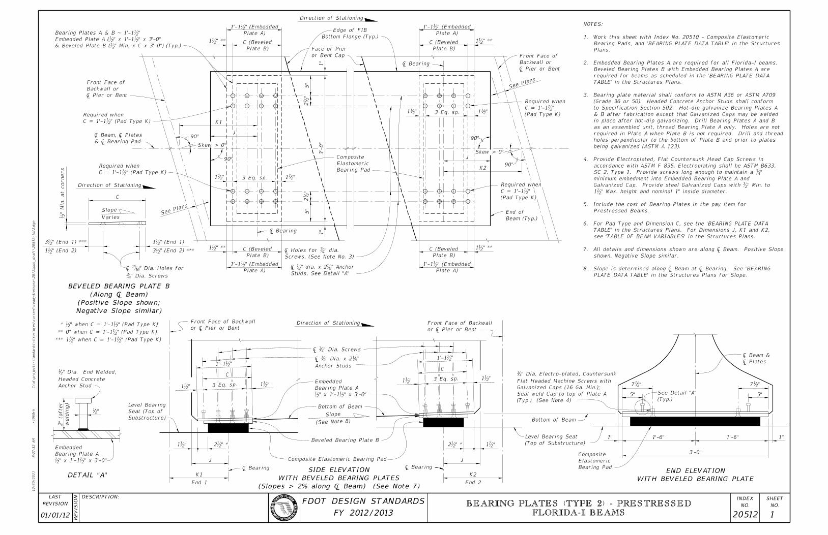
PLATE DATA TABLE’ in the Structures Plans for Slope.
8. Slope is determined along â�� Beam at â�� Bearing. See ’
shown, Negative Slope similar.
7. All details and dimensions shown are along � Beam. Positive
see ’TABLE OF BEAM VARIABLES’ in the Structures Plans.
TABLE’ in the Structures Plans. For Dimensions J, K1 and K2,
6. For Pad Type and Dimension C, see the ’BEARING PLATE DATA
Prestressed Beams.
5. Include the cost of Bearing Plates in the pay item for
1‰" Max. height and nominal 1" inside diameter.
Galvanized Cap. Provide steel Galvanized Caps with ‰" Min. to
minimum embedment into Embedded Bearing Plate A and
SC 2, Type 1. Provide screws long enough to maintain a ¾"
accordance with ASTM F 835. Electroplating shall be ASTM B633,
4. Provide Electroplated, Flat Countersunk Head Cap Screws in
being galvanized (ASTM A 123).
holes perpendicular to the bottom of Plate B and prior to plates
required in Plate A when Plate B is not required. Drill and thread
as an assembled unit, thread Bearing Plate A only. Holes are not
in place after hot-dip galvanizing. Drill Bearing Plates A and B
& B after fabrication except that Galvanized Caps may be welded
to Specification Section 502. Hot-dip galvanize Bearing Plates A
(Grade 36 or 50). Headed Concrete Anchor Studs shall conform
3. Bearing plate material shall conform to ASTM A36 or ASTM A709
TABLE’ in the Structures Plans.
required for beams as scheduled in the ’BEARING PLATE DATA
Beveled Bearing Plates B with Embedded Bearing Plates A are
2. Embedded Bearing Plates A are required for all Florida-I beams.
Plans.
Bearing Pads, and ’BEARING PLATE DATA TABLE’ in the Structures
1. Work this sheet with Index No. 20510 - Composite Elastomeric
NOTES:
01/01/12 20512 1
BEARING PLATES (TYPE 2) - PRESTRESSED
FLORIDA-I BEAMS
12/30/2011
8:2
7:3
3
AM
RE
VISIO
N
C:\
d\projects\standards\structures\current\ready4rele
ase\2012book_draft\20512-2of2.d
gn
NO.
SHEET
NO.
INDEX
rd960rh
DESCRIPTION:
REVISION
LAST
FY 2012/2013
FDOT DESIGN STANDARDS
(Typ.)
See Detail "A"
1"1"(Top of Substructure)
Level Bearing Seat
Bottom of Beam
WITHOUT BEVELED BEARING PLATE
END ELEVATION
or � Pier or
Front Face of Backwall
or � Pier or
Front Face of Backwall
or � Pier or
Front Face of Backwall
Bottom of Beam
Bottom of Beam
Composite Elastomeric Bearing Pad
Composite Elastomeric Bearing Pad
See Structures Plans
(Top of Substructure)
Sloped Bearing Seat
See Structures Plans
(Top of Substructure)
Sloped Bearing Seat
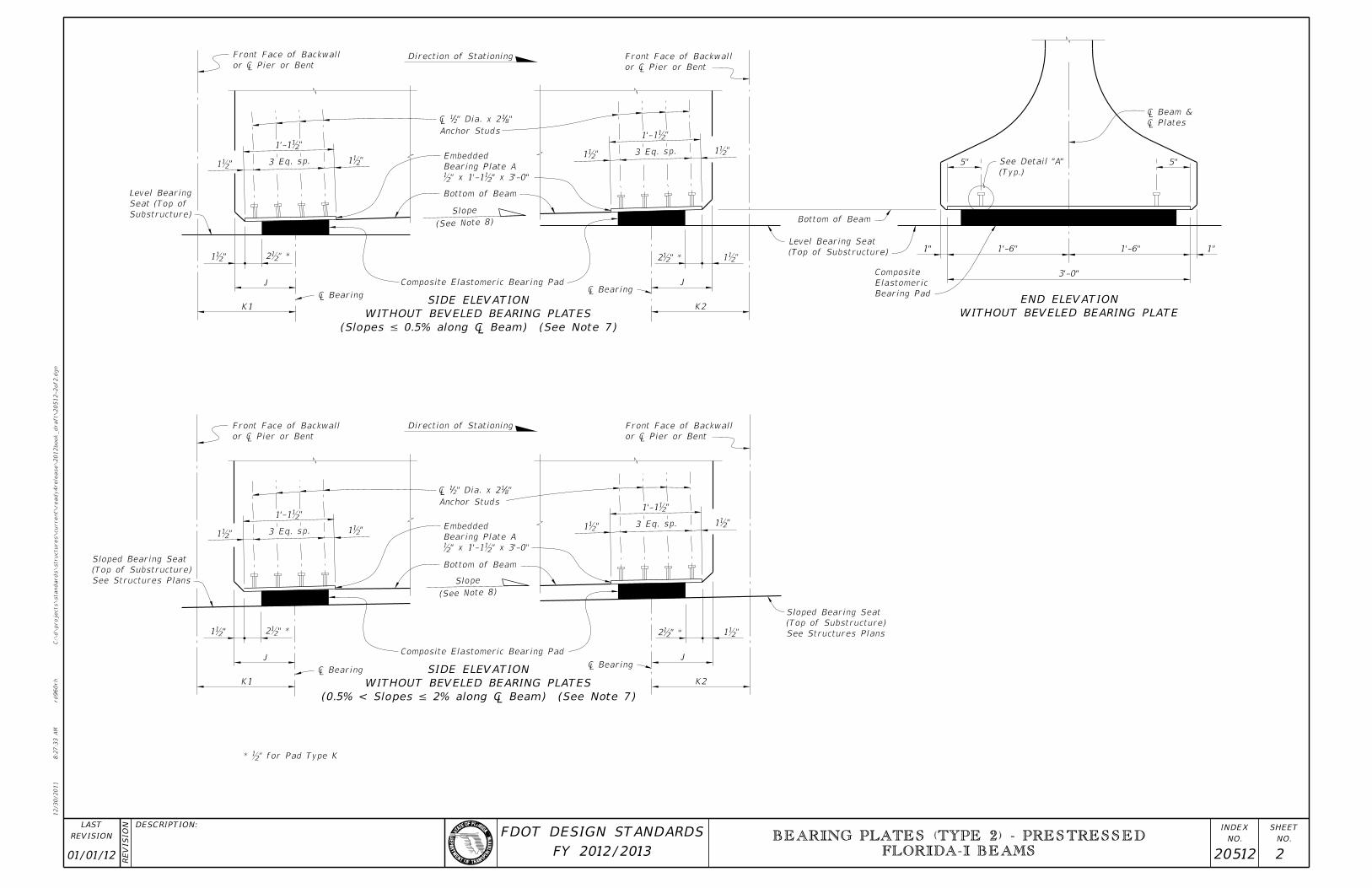
(Slopes â�⁄ 0.5% along â�� Beam) (See
WITHOUT BEVELED BEARING PLATES
SIDE ELEVATION
(0.5% < Slopes â�⁄ 2% along â�� Beam) (See
WITHOUT BEVELED BEARING PLATES
SIDE ELEVATION
� P
� Be
J
K1
or � Pier or
Front Face of Backwall
Substructure)
Seat (Top of
Level Bearing
J
K1
J
Direction of Stationing
Direction of Stationing
K2
5" 5"3 Eq. sp.
3 Eq. sp.
3 Eq. sp.3 Eq. sp.
Anchor Studs
"81" Dia. x 22
1�»
Anchor Studs
"81" Dia. x 22
1�»
� Be
� Be
� Be
� Be
Bearing Pad
Elastomeric
Composite
1’-6"1’-6"
3’-0"
(See Note 8)
Slope
(See Note 8)
Slope
K2
J
1’-1‰"
1’-1‰"
* ‰" for Pad Type K
‰" x 1’-1‰" x 3’-0"
Bearing Plate A
Embedded
‰" x 1’-1‰" x 3’-0"
Bearing Plate A
Embedded
1’-1‰"
1’-1‰"
2‰" *1‰"
1‰" 2‰" *
"‰1" *‰2
" *‰2 "‰1
1‰""‰1
1‰""‰1
1‰""‰1
1‰""‰1
01/01/12 20512 2
BEARING PLATES (TYPE 2) - PRESTRESSED
FLORIDA-I BEAMS