Embed Size (px)
Citation preview
Quantitative Measurement of Adhesion Between Polypropylene Blends and Paints
by Tensile Mechanical Testing HOUXIANG TANG, BRENDAN FORAN, and DAVID C. MARTIN*
Department of Materials Science and Engineering and the Macromolecular Science and Engineering Center
The Uniuersity of Michigan, Ann Arbor Ann Arbor, MI, 481 09-21 36
A tensile mechanical test suitable to measure the adhesion between brittle coat- ings and ductile substrates was applied to measure the adhesion of painted layers on polypropylene blends. The test involves the tensile deformation of the painted assembly, resulting in the periodic cracking of the brittle coating on the ductile substrate. The interfacial shear strength was determined by measuring the strength of the coating, the thickness of the coating, and the average width of paint fragment after the crack density reaches saturation. Apparent interfacial shear strength was obtained for different paints on the same kind of blend, which gave consistent results over the experimental strain rate range from 10-4 to 10-3 sec-'. Interfacial delamination was studied by optical microscopy (OM) and transmission electron microscopy (TEM). The delamination was observed to mainly occur near the adhesion promoter and substrate interface.
INTRODUCTION requirement for the critical evaluation of current
olypropylene blends have been widely used in the P automotive industry, because of their excellent combination of properties such as low cost, low den- sity. processability, high modulus, and relatively high toughness (1). An important class of polypropylene blends are the thermoplastic olefins or TPOs, which are primarily isotactic polypropylene toughened by the addition of up to 20 - 40% rubber particles. They may atso contain compatibilizers and dimensional stabilizers such as mica. One important application of TPOs in automotive is in exterior panels, which are generally painted. For the sake of protection and ap- pearance, the adhesion between paint and TPO sub- strate is an important concern. However, because of their low surface energy, lack of reactive groups, low porosity, and weak surfaces, PP blends inherently have a poor adhesion with paints (2). Methods that have been explored to improve the adhesion between PP blends and paints include surface treatments, polymer modification, application of adhesion promot- ers, and development of novel paint materials (3). Quantitative measurements of the adhesion strength and characterization of the interfacial deformation be- tween PP blends and paints are therefore not only a
'Corresponding author. Email. [email protected]
440
painted systems, they are also important for develop- ing new approaches.
Considerable attention has been paid to the quanti- tative measurement of thin coating adhesion as de- scribed in several reviews (4-8). Frequently used tests for quantitatively measuring adhesion between thin coatings and substrates are the indentation test and scratch test. During the indentation test, a mechani- cally stable crack is introduced into the coating-sub- strate interface and the mechanical properties are deduced from the load-depth curve upon unloading (7). Loads high enough to delaminate well-adhering coatings can be produced during indentation. The ad- hesion energy can be calculated given the size of the circular crack, the indentation volume, and the me- chanical properties of the coating material (91. An ac- curate description of the stress field around the in- dentation is essential to predict the occurrence of delamination, which is influenced by both the thick- ness of the coating and the mechanical properties of both the coating and the substrate. There is not yet any ideal approach for this problem that is applicable to every case. Derived from the indentation test, the scratch test involves drawing a stylus over the coating surface with a stepwise or continuously increasing normal force until the coating detaches (6). Similarly, the interpretation of scratch test also involves a de- scription of the stress field around the scratching
POLYMER ENGlNEERlNG AND SCIENCE, MARCH 2001, Vol. 41. No. 3
Quantitative Meaurement of Adhesion
channel. With the aid of acoustic microscopy, remark- able progress has been made in characterizing the stress field around the scratching notch. However, there is still room for theoretical developments to take into account the influence of coating thickness and coating material. Another limitation of both the inden- tation test and the scratch test is that they require specific instruments that might not be available to general laboratories.
THEORY Tensile mechanical tests to measure adhesion en-
ergy were initially formulated by Chow et d based on G S t h energy balance model for the study of a thin brittle film on a polymeric substrate (10-12). This model was then extended to the case in which the substrate might display plastic deformation (13). How- ever, their formulation for adhesion energy requires information about the mechanical properties of the thin film. such as the Poisson's ratio, which in some cases are difficult to measure accurately.
To quantitatively measure the shear strength of a metal-ceramic interface, Agrawal and Raj (14, 15) de- veloped a theoretical model in terms of more readily measurable quantities. Their model was based on the commonly used single-filament-composite test to measure the apparent interfacial shear strength of a fibrous composite (16). When a tensile load is applied to a ductile substrate coated by a thin brittle film, shear stresses will develop across the substrate-coat interface. As the tensile strain in the film increases, the less-ductile film will break repeatedly at its weak points. Film fragments longer than a critical length l,- are prone to further fragmentation, while film fragments shorter than & will not break further. The crack spacing will be randomly distributed between l,- and &/2 and the shear strength is given by
where 5 is the paint thickness. & the maximum spacing of crack at saturation, and uJ the fracture stress of thin film.
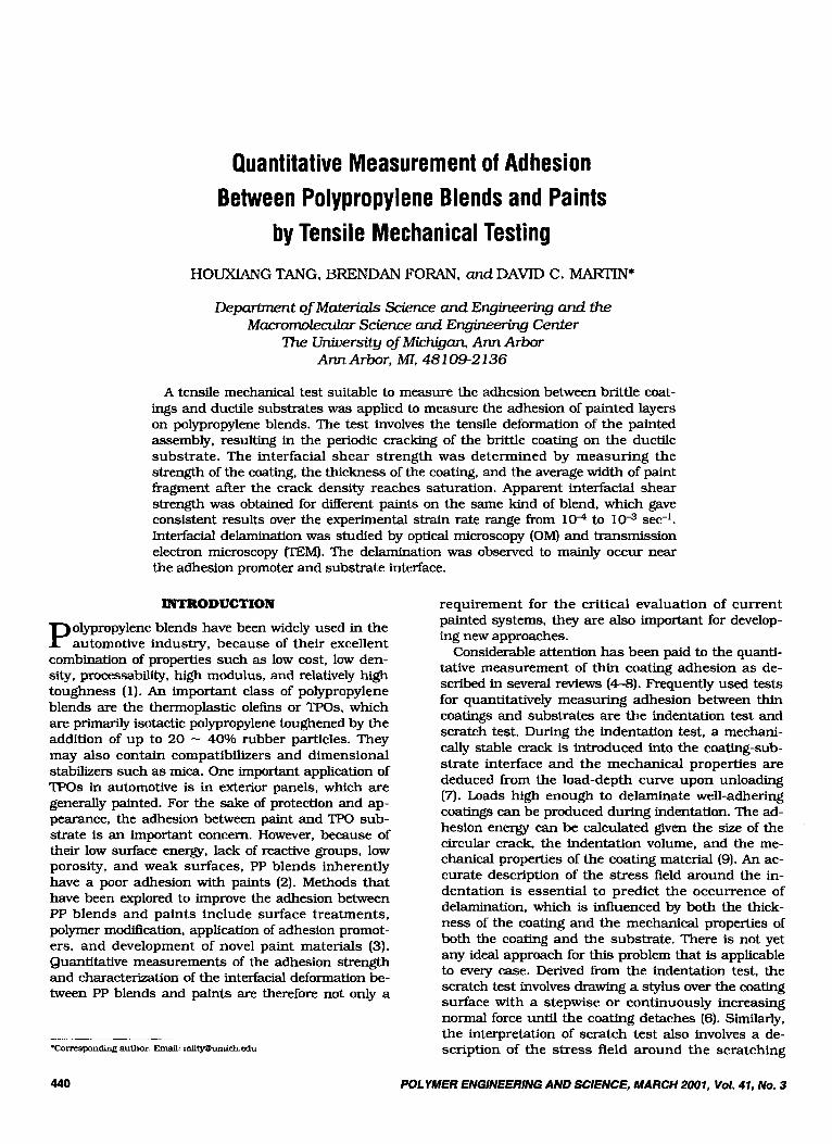
Leterrier et al. (17-19) developed a model to mea- sure the interfacial shear strength between thin glass coatings and polymer films. Their approach was also derived from the single-filament-composite test and their modeling of interfacial stress transfer followed the shear-lag analysis (16). The stress distribution at the interface and in the paint layer was calculated from the equilibrium of a small element of the paint subjected to a tensile force parallel to the interface (Rg. 1). The equilibrium force balance requires:
h P 7
a h , -- _ -
where up is the stress in paint along the loading direc- tion x; T the interfacial shear stress: and hp the thick- ness of the paint. Ignoring the end effects of the paint, assuming that the substrate is perfectly plastic (i.e. the interfacial shear stress is constant), and the paint tensile strength is independent of the fragment size, Eq 2 can be integrated:
(3)
As before u- is defined as the tensile strength of paint, and 4 the critical length of the paint over which the tensile stress in the paint will reach the tensile strength. However, in practice, it is more suitable to measure the average crack length instead of the maxi- mum crack length which might be strongly influenced by processing defects or inadvertent delamination appearing at the interface. Some authors (6, 20) proposed that the crack spacing would have an even - distribution between 1= and LJ2, which leads to 1 = 3/44. An even distribution of crack spacing, how- ever, has not been confirmed in experimental observa- tions. In a study of cracking in reinforced concrete, Beeby (21) proposed that 5 = 1.33IJ2. Kimber and Keer (22) further showed theoretically that the fre- quency m(l) for the occurring of a crack of length 1 (4/2 < Z < 4) is given by Z-lrn(1) = &/2, where C is a constant. Numerically solving for C gave:
1 = 1.337&/2
Polymer Substrate - I 1 - Fig. I . Shear-lag stress analysis.
POLYMER ENGINEERING AND SCIENCE, MARCH 2001, Vol. 41, No. 3 441

Houxiang Tang, Brendan Form, and David C. Martin
Combining JQ 4 into Eq 3 and rewriting results in:
=m T = 1.337%-
1 (5)
Thus given the tensile strength of the paint (am) and the film thickness (v, measurements of the average crack spacing at saturation (0 will give an estimate of the apparent shear strength at the interface between paint and substrate.
Most of the research published so far has focused on mono-layer, brittle, and hard films. However, in practice, most paint systems consist of several layers of materials, including top coat, base coat, and adhe- sion promoter or primer layers. In our research, we have applied the model mentioned above to multi- layer paint systems on TPO substrates and have char- acterized the deformation at the interface between paint and substrate.
EXPERIHENTAL
Painted TPO samples were supplied by DuPont Au- tomotive Products. For tensile mechanical tests, sam- ples were cut into a dog-bone tensile testing bar of - 10 cm length and - 1.1 cm width with a router. The edges of sample were polished with abrasive paper up to 1200 grit. Mechanical tests were conducted on an InstronTM 1137 machine with strain rates between
and 10-4 sec-I. A CCD camera with a 1OX objec- tive lens was used to monitor the testing process. The test was recorded with a VCR connected to the CCD camera. By replaying the tape, images were digithd and stored on a Macintosh Quadra computer with a RasterOps image acquisition board. The change in crack density with the strain was obtained by mea- suring the crack spacing with the NIH Image program. The cross sections of the cracked sample were studied by optical microscopy (OM). A sample cut directly from a 1996 Ford Taurus bumper was also tested, which had a Vehicle Identification Number (VIN) of IFALP52U7TG- 119400. The bumper was obtained from Fox's Auto Parts in Bellme, MI. A microtomed slice from that sample was observed by transmission electron microscopy ('EM).
RESULTS AND DISCUSSION
Substrates of samples tested were injection-molded TPO. Three kinds of samples were tested. One of them was a TPO substrate coated by a black coat, which will be referred to as General Black in the text follow- ing. The paint on another sample was composed of a base coat and a clear coat on top of it; and this sam- ple will be referred as Flex Clear. The basecoats are conventional, one component, high-solids solvent- borne basecoats based on melamine crosslinking. The clearcoats are conventional two component, iso- cyanate crosslinked solvent-borne, acrylic clearcoat. Both samples mentioned above have an adhesion pro- moter layer between the paint and the substrate. For comparison, painted TPO samples without an adhesion
promoter layer were also tested. The Ford Taurus sample has a similar structure to the Flex Clear sam- ple. Optical microscopy images of these three samples are shown in Flg. 2 respectively.
For samples without an adhesion promoter layer, the whole paint layer peeled off fi-om the substrate be- fore cracks could develop across the width of sample, which clearly reflected the poor interfacial adhesion of these materials. For samples with an adhesion pro- moter layer, the crack density would increase with strain level. An example, shown in Flg. 3. is the crack- ing procedure on a Flex Clear sample. The cracks could be clearly observed, and checking at high mag- nification by optical microscope did not reveal micro- cracks on the sample. Generally, cracks tended to ini- tiate from the two sides of the dog-bone sample in unpolished samples. After the polishing step, more cracks were observed to initiate from the middle of the sample and thus the effect of sample preparation on the final result was minimized. Cracks usually propa- gated across the width of the sample as shown in Fig. 3. Average crack widths were measured at both edges and these two values were very close. The delamina- tion of the paint from the substrate only happened after the local crack density reached saturation. Occa- sionally, local delamination of paint was observed where there was local necking of the sample.
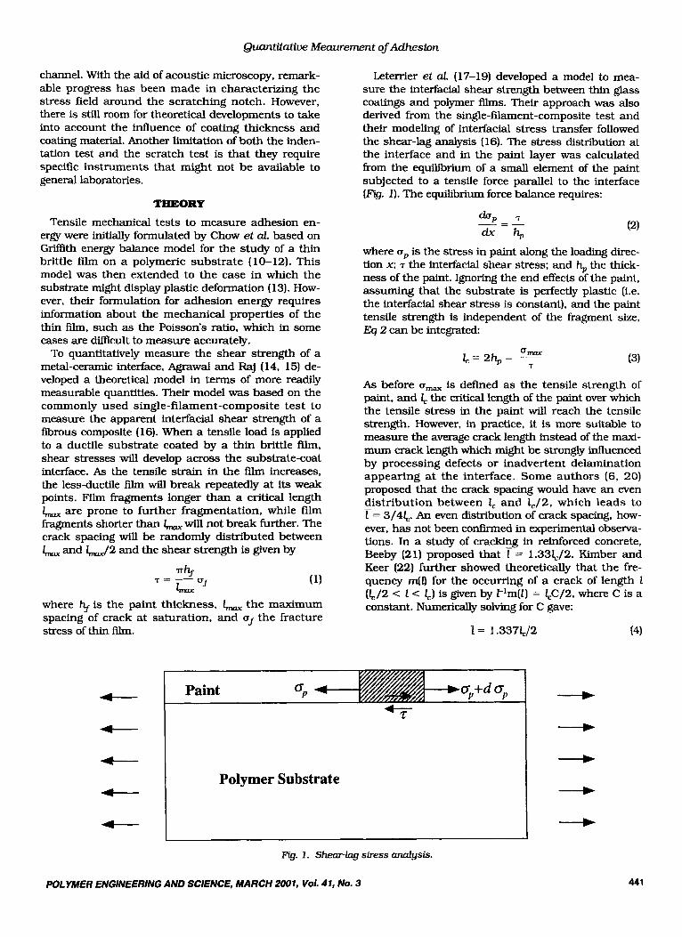
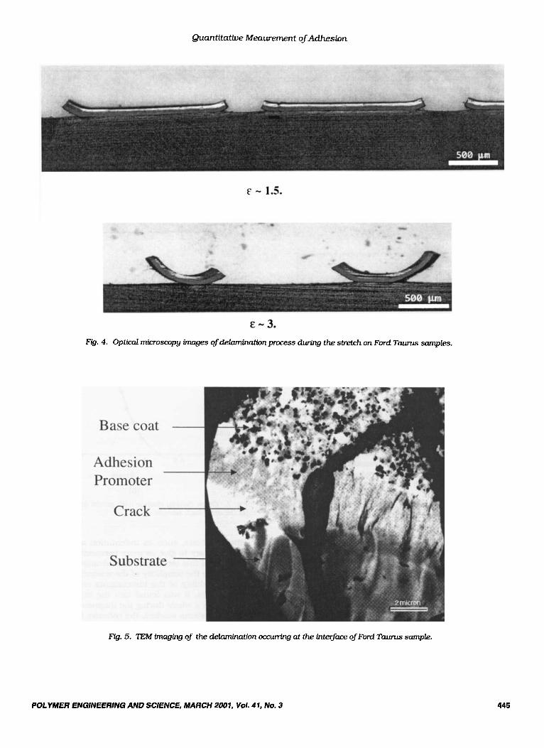
Optical microscope images (Fig. 4) showed that de- lamination occurred at the interface between the adhe- sion promoter and the substrate. This was also ob- served in "EM images (Fig. 5). There was some evidence showing the tearing of material from the TPO substrate. As we have mentioned above, since delamination only occurred near the end of cracking process, the ob- served tearing of substrate should not significantly in- fluence the crackmg process and final crack density. Although we did once observe fracture of the top paint while the base paint remained intact, in every other case, the multi-layer paint fractured as a whole. Therefore, it is reasonable to believe that the single case of crack arrested at the interface of top coat and base coat was caused by some inadvertent factor, and its influence on the final results of measurement should be negligible.
Shown in Ftg. 6 are the distributions of the crack width after the saturation of the crack density for both the Flex Clear and the General Black samples. It can be seen that the distributions of crack width are far from even and the average crack width is closer to the lower limit than to the upper limit. This observa- tion qualitatively agrees with theoretical prediction. The crack density increased with strain, reaching a saturated limit at high strains, as shown in Ftg. 7. For Flex Clear paint. cracking began at a strain level of -0.42 and reached saturation at a strain of -0.54. The General Black paint cracked between a strain range from -0.35 to -0.70. These cracking strain ranges (q) were quite reproducible for each kind of paint. The fact that the brittle films remain adherent to the substrate after failure makes it possible for this
442 POLYMER ENGINEERING AND SCIENCE, MARCH 2001, Vol. 41, No. 3

Quantitative Meaurement of Adhesion
FYg. 2. Optical microscopy images of samples t e s w (4) Flew Clear paint sample, (b) General Black paint sample, (c) sample cutfrom Ford Taurus bumper.
test to reveal information about the distribution of strength in the coated layers. We could obtain free standing films of the paint material by painting the TPO plaque without adhesion promoter layer and then peeling off the paint afterwards. Tensile strengths of both paints were measured as shown in Table 1.
POLYMER ENGINEERING AND SCIENCE, MARCH 2001, Vol. 41, No. 3
Assuming that the tensile strength of painted coat- ing has the same value as the free standing film, the apparent shear strength at the interface was calcu- lated according to Eq 5 and the values obtained are listed in Table 1. In OUT calculation, we ignored the pos- sible influence of the thin layer of adhesion promoter,
443

Hownhng Tang, Brendan Foran, and David C. Martin
Q. 3. Cracking process during tensile stretch on a Hex Clear paint sample.
and considered the multi-layer film as a coherent unit. For General Black paint, the apparent interfacial shear strength was calculated to be 2.88 MPa, which is about 3.7 times smaller than the paint tensile strength (10.6 MPa). The Flex Clear paint had a higher apparent interfacial shear strength of 3.21 MPa, and the ratio between the apparent interfacial strength and the paint tensile strength is about 2.30. In this case, without adhesion promoter, the esti- mated apparent interfacial shear strength was smaller than 0.02 MPa.
Indentation and scratch methods for measuring in- terfacial adhesion generally produce remarkable vari- ations in measurement results, which sometime reaches two orders of magnitude (23). To check the re- producibility of the tensile mechanical technique, tests were conducted on same kind of samples at dif- ferent strain rates. The measured crack spacing was consistent (shown in Fig. 8) over the experimental strain rate range of 1 w to lW3 sec-' . For Flex Clear paint, the measured average crack spacing changes between 0.45 mm (displacement rate 1 in/min) and
444 POLYMER ENGINEERING AND SCIENCE, MARCH 2001, Vol. 41, No. 3
Quantitative Meaurement of Adheslon
Fig. 4. Opticd microscopy images of delamination process during the stretch on Ford Taunrs samples.
m. 5. TEM of the de!mnim&bn occurring at the ir&er@e ofhrd Taurus sample.
POLYMER ENGfNEERllVG AND SCIENCE, MARCH 2007, Vol. 41, No. 3 445

HowriQrq Tang, Brendan Foran, and David C. Martin
(b) Rg. 6. Crack-width distribution at saturation (4) Flex Clear and b) General Black sample.
0.67 mm (displacement rate 0.5 in/min). while for General Black paint, a nearly constant average crack spacing of 0.31 mm was measured all over the experi- mental range of strain rate. The higher deviation mea- sured in Flex Clear sample might be due to a higher density of defects at the interface: this may also ex- plain the broader distribution of crack spacing after saturation of crack density.
More detailed experimental observations and simu- lations of the near interface deformation during the tensile test are now underway. Preliminary observa- tion with polarized light OM have shown significant birefi-ingence near the interface after the sample was stretched in tension. Further results will be published later.
coNcLusIoNs
We have described a tensile mechanical test to mea- sure the apparent interfacial shear strength between multi-layer paints and PP blends. This method is gen- erally applicable to brittle coatings on ductile sub- strates. Corroborative tests on these same samples by
Strain
(b) Ffg. 7. Cmck density change with strain: (4) k Clear and (b) General Black sample.
other methods, such as indentation and scratching are necessary to give us more perspective and under- standing of this technique. The advantages of this ap- proach are the simplicity of the analysis and the gen- eral availability of the instruments required. In our experiments, it was found that the multi-layer paint cracked as a whole during the fragmentation process. For the systems studied, the cohesive failure of paint (cracking) occurred before the adhesive failure be- tween paint and substrate (delamination). Microscopy showed that the delamination occurred at the inter- face between the adhesion promoter and the TPO sub- strate for systems studied. The measured average crack spacing was reproducible and insensitive to
446 POLYMER ENGINEERING AND SCIENCE, MARCH 2001, Vol. 41, No. 3

Quantitative Meaurement of Adhesion
Table 1. Parameters and Test Results for Three Kinds of Samples. ~~ ~~~
Clear paint Base paint Promoter Tensile Tensile Interfacial thickness thickness thickness strength modulus shear
strength
Flex Clear 114 prn 78 prn 2.5 prn 7.4 MPa 195 MPa 3.21 MPa General Black NIA 58 prn 5-6prn 10.6 MPa 410 MPa 2.88 MPa Flex Clear 114 prn 78 prn NIA 7.4 MPa 195 MPa < 0.02 MPa no promoter
0 0.2 0.4 0.6 0.8 1 1.2
Displacement rate (in/min)
Flg. 8. Crack width (m us. displacement rate (strain rate range 1 [-X-).
- 1 C3/sec): geneml black paint (-u-), and Flex clear paint
strain rate over the investigated range (lo4 - sec-’). Quantitative measurements of the apparent in- terfacial shear strength of the paint systems were ob- tained based on the measured average crack spacing at saturation. The interfacial shear strength of the paint systems measured were 2.3 - 3.7 times lower than the cohesive tensile strength of the paint materi- als studied.
ACKNOWLEDGMENTS
This research was partly supported by DuPont Au- tomotive Co. Samples tested in experiments were pro- vided by Dr. Robert Matheson.
REFERENCES: 1. B. Franslow and P. Samacke, in TPOs In Automotive,
2. Teltec Resources Network Corp Report, Adhesive Age,
3. R F. Pierce, in ?pas In Automotive, E M , Inc. (1995).
ECM, Inc. (1995).
October 1996.
4. R. Lambourne, in Paint and Surface Coatings, Theory and Practice, p. 662, R Lambourne. ed., John Wiley & Sons, NewYork (1987).
5. M. R. Lin, J. E. Ritter, L. Rosenfeld, and T. J. Lardner, J. Mater. Res., 6, 1110 (1990).
6. P. R. Chalker, S. J. Bull, and D. S. Rickerby, Mater. Sci Eng., A140, 583 (1991).
7. G. M. Pharr and W. C. Oliver, MRS Bulletin. July 1992, p. 28.
8. H. Ollendorf and D. Schneider, Surface and Coating Techml., 113,86 (1999).
9. J. E. Ritter. T. J. Lardner, L. Rosenfeld. and M. R. Lin, J. Appl. Phys., 66, 3626 (1989).
10. T. S. Chow, Adhesion of Brittle FiLms on a Polymeric Sub- strate, Bulletin of the American Physical Society, Denver (March 1975).
11. T. S. Chow, Adhesion Sci and TechnoL, BB, 687 (1975). 12. T. S. Chow, C. A. Liu. and R C. Penwell, J. Polym Sci:
Polym Phys. ECL, 14, 1305 (1976). 13. A. Davutoglu and I. A. Aksay, Surface and lnte@mes in
Ceramic and Ceramic-Metal System, p. 641, J. Pask and A. Evans, eds., Plenum Press (1980).
14. D. C. Agrawal and R. Raj, Acta. Metall., 37, 1265 (1989).
POLYMER ENGINEERING AND SCIENCE, MARCH 2001, Vol. 41, No. 3 447

Houxiang Tang, Breruian Foran, and David C. Martin
15. R. S. Goldman, Master’s thesis, Cornell University, Ithaca, N. Y. (1992).
16. A. Kelly and W. R. vson. J. M e c h Phys. SOL. 13, 329 ( 1965).
17. Y. Leterrier, Y. Wyser, J.-A. Mbson, and J. Hilbom, J. Adhesion. 44,213 (1994).
18. Y. Leterrier, J. Andersons, Y. Pitton, and J.-A. E. M h - son, J. Polym Sci: Polym Phys. Ed., 35, 1449 (1997).
19. Y. Leterrier. L. Boogh. J. Andersons, and J.-A. E. M b - son; J. Polyrn Sci: Polym Phys. Ed., 36. 1463 (1997).
20. L. Dilandro, A. T. DiBenedetto, and J. Groeger; Polyrn
2 1. A. W. Beeby. The Structural Engineer, S 7 4 9 (1979). 22. A. C. Kimber and J. G. Keer, J. Mater. Sci Lett, 1, 353
( 1982). 23. H. Ji, G. S. Was. and M. D. Thouless, Fundamentals of
Nanoindentation and Nanotribology, MRS Symp. Roc., 523,325 (1998).
Compos., B, 209 (1988).
448 POLYMER ENGINEERING AND SCIENCE, MARCH 2001, Vol. 41, No. 3