Embed Size (px)
Citation preview
ASMEL-200 / -500 / -680 / -1000 BETRIEBSANLEITUNG | OPERATING MANUAL
Technische Änderungen vorbehalten. Alle Angaben ohne Gewähr. Alle Rechte liegen bei der ASUTEC GmbH. Subject to technical modifications. No responsibility is accepted for the accuracy of this information. All rights are reserved by ASUTEC GmbH.
Document nr. 85000065 – Version A – 2019/06/17 – M. Pohle WWW.ASUTEC.EU | 1
BETRIEBSANLEITUNG
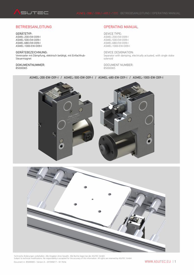
GERÄTETYP: ASMEL-200-EW-D09-I ASMEL-500-EW-D09-I ASMEL-680-EW-D09-I ASMEL-1000-EW-D09-I
GERÄTEBEZEICHNUNG: Vereinzeler mit Dämpfung, elektrisch betätigt, mit Einfachhub-Steuermagnet
DOKUMENTNUMMER: 85000065
OPERATING MANUAL
DEVICE TYPE: ASMEL-200-EW-D09-I ASMEL-500-EW-D09-I ASMEL-680-EW-D09-I ASMEL-1000-EW-D09-I
DEVICE DESIGNATION: Separator with damping, electrically actuated, with single stoke solenoid
DOCUMENT NUMBER: 85000065
ASMEL-200-EW-D09-I / ASMEL-500-EW-D09-I / ASMEL-680-EW-D09-I / ASMEL-1000-EW-D09-I
ASMEL-200 / -500 / -680 / -1000 BETRIEBSANLEITUNG | OPERATING MANUAL
Technische Änderungen vorbehalten. Alle Angaben ohne Gewähr. Alle Rechte liegen bei der ASUTEC GmbH. Subject to technical modifications. No responsibility is accepted for the accuracy of this information. All rights are reserved by ASUTEC GmbH.
Document nr. 85000065 – Version A – 2019/06/17 – M. Pohle WWW.ASUTEC.EU | 2
INHALTSVERZEICHNIS
CONTENTS
1 Allgemeine Hinweise 1.1 Identifikationsdaten ............................................... 3 1.2 Bestimmungsgemäße Verwendung ........................ 3 1.3 Sachwidrige Verwendung / Vorhersehbarer Missbrauch .................................... 3 1.4 Haftung ................................................................. 3 1.5 Garantieausschluss ................................................. 3 1.6 Umweltschutz / Entsorgung .................................... 4
1 General information 1.1 Identification data.................................................. 3 1.2 Intended use ......................................................... 3 1.3 Improper use / Foreseeable misuse ......................... 3 1.4 Liability.................................................................. 3 1.5 Exclusion of warranty ............................................. 3 1.6 Environmental protection / Disposal ........................ 4
2 Sicherheitshinweise 2.1 Warnhinweise in der Betriebsanleitung ................... 4 2.1.1 Erscheinungsbild und Struktur der Warnhinweise ........................................... 4 2.1.2 Kennzeichnung der Warnhinweise ............. 4 2.2 Sicherheitsvorschriften für das Personal ................... 5 2.3 Voraussetzungen für den Einbauort ........................ 5 2.4 Sicherheitsvorschriften für Betriebselektrik .............. 5
2 Safety instructions 2.1 Warnings in this manual ........................................ 4 2.1.1 Appearances and structure of the warnings................................................... 4 2.1.2 Labeling of warnings ................................. 4 2.2 Safety regulations for personnel ............................. 5 2.3 Requirements for the installation location ............... 5 2.4 Safety regulations for operating electronics............. 5
3 Technische Daten 3.1 Ausführung und Gewicht ....................................... 6 3.2 Arbeitsbereich........................................................ 6 3.3 Vortriebskraft ........................................................ 6 3.4 Staudruck .............................................................. 6 3.5 Zyklenzeiten .......................................................... 6 3.6 Funktion ................................................................ 6 3.7 Elektrischer Anschluss ............................................ 7 3.8 Elektrische Daten ................................................... 7 3.9 Temperaturbereich ................................................. 7
3 Technical details 3.1 Execution and weight ............................................ 6 3.2 Operating range .................................................... 6 3.3 Propulsive force ..................................................... 6 3.4 Ram pressure......................................................... 6 3.5 Cycle times ............................................................ 6 3.6 Function ................................................................ 6 3.7 Electrical connection .............................................. 7 3.8 Electrical Data ........................................................ 7 3.9 Temperature range ................................................ 7
4 Transport ........................................................................ 7
4 Transport ........................................................................ 7
5 Montage 5.1 Sicherheit bei der Montage .................................... 7 5.2 Montage am Einsatzort .......................................... 7 5.3 Montage induktiver Sensoren ................................. 8 5.4 Tausch der Dämpfeinheit........................................ 9 5.5 Abmessungen ........................................................ 10
5 Installation 5.1 Safety for installation ............................................. 7 5.2 Installation at the place of use ................................ 7 5.3 Installation of inductive sensors .............................. 8 5.4 Replacement of damping unit ................................ 9 5.5 Dimensions ........................................................... 10
6 Funktionsablauf .............................................................. 11
6 Functional sequence........................................................ 11
7 Wartung 7.1 Sicherheit bei der Wartung ..................................... 12 7.2 Wartungsarbeiten .................................................. 12
7 Installation 7.1 Safety during maintenance .................................... 12 7.2 Maintenance work ................................................. 12
8 Typenschlüssel ................................................................ 13
8 Type codes ..................................................................... 13
9 Lieferumfang und Zubehör .............................................. 14
9 Scope of supply and accessories ...................................... 14
10 Einbauerklärung .............................................................. 15
10 Copy of the declaration of incorporation.......................... 15
ASMEL-200 / -500 / -680 / -1000 BETRIEBSANLEITUNG | OPERATING MANUAL
Technische Änderungen vorbehalten. Alle Angaben ohne Gewähr. Alle Rechte liegen bei der ASUTEC GmbH. Subject to technical modifications. No responsibility is accepted for the accuracy of this information. All rights are reserved by ASUTEC GmbH.
Document nr. 85000065 – Version A – 2019/06/17 – M. Pohle WWW.ASUTEC.EU | 3
1 ALLGEMEINE HINWEISE 1 GENERAL INFORMATION
1.1 IDENTIFIKATIONSDATEN 1.1 IDENTIFICATION DATA Typ-Bezeichnung: Vereinzeler mit Dämpfung, elektrisch betätigt, mit Einfachhub-Steuermagnet Herstelleranschrift, Kundendienst und Ersatzteile: ASUTEC GmbH, Küferstraße 11, 73257 Köngen, Deutschland Dokumentnummer und Version: 85000065 – Version A
Type designation: Separator with damping, electrically actuated, with single stroke solenoid. Manufacturer address, aftersales service and spare parts: ASUTEC GmbH, Küferstraße 11, 73257 Köngen, Germany Document number and version: 85000065 – Version A
1.2 BESTIMMUNGSGEMÄßE VERWENDUNG 1.2 INTENDED USE Der elektrischeische Vereinzeler: - darf ausschließlich nur mit den in Kapitel 3 angegebenen elektrischen Anschlusswerten betrieben werden! - ist konzipiert für den Betrieb in geschlossenen Räumen! - ist bestimmt für die Werkstückträgervereinzelung im Transfersystem ohne Mitnehmer (Stauförderer)! - stoppt einen oder mehrere auflaufende Werkstückträger an einer definierten Werkstückträger-Anschlagfläche! - ist bestimmt für den Einbau in eine Maschine – Die An- forderungen der zutreffenden gesetzlichen Richtlinien für Gesundheitsschutz und Maschinensicherheit müssen beachtet und eingehalten werden! - darf nur in der angegebenen Transportrichtung belastet werden! - darf nur im Originalzustand und mit Originalzubehör betrieben werden! - darf nur im Rahmen der definierten Einsatzparameter (siehe Kapitel 3 technische Daten) verwendet werden!
The electrically separator: - May only be operated with the electrical connection values given in chapter 3! - is designed for indoor operation! - is intended for stopping and for the separation of the workpiece carriers in the transfer system. In the stopping process the conveyor media continues moving under the workpiece carrier (accumulation conveyor). A positive connection between workpiece carrier and conveyor media is not allowed! - stops one or more accumulated workpiece carriers on a defined workpiece carrier stop surface! - is intended for installation in a machine - The requirements of the applicable legal directives for health protection and machine safety must be observed and complied with! - may only be loaded in the specified direction of transport! - may only be used in its original condition and with original accessories! - may only be used within the scope of the defined application parameters (see chapter 3 technical data)!
1.3 SACHWIDRIGE VERWENDUNG / 1.3 INPROPER USE /
VORHERSEHBARER MISSBRAUCH FORESEEABLE MISUSE Eine Sachwidrige Verwendung liegt vor, wenn der Vereinzeler: - nicht entsprechend den obigen Bestimmungen verwendet wird. - in vibrationsgefährdeten oder explosionsgefährdeten Bereichen betrieben wird. - als Sicherheitsschalter verwendet wird. - im Betrieb im direkten Kontakt mit verderblichen Gütern steht.
An improper use is when the separator: - is not used according to the above provisions. - is operated in vibration-prone or potentially explosive atmospheres. - is used as a safety switch. - is in direct contact with perishable goods.
1.4 HAFTUNG 1.4 LIABILITY Grundsätzlich gelten unsere Lieferungs- und Zahlungs-bedingungen. Diese stehen dem Betreiber spätestens seit Vertrags-abschluss zur Verfügung. Für Beistellungen von Fremdherstellern durch den Auftraggeber und/oder von Dritten übernimmt die Firma ASUTEC GmbH keine Haftung für deren Betriebssicherheit. Gewährleistungs- und Haftungsansprüche bei Personen- und Sachschäden sind ausgeschlossen, wenn sie auf eine oder mehrere der folgenden Ursachen zurückzuführen sind: - nicht bestimmungsgemäße Verwendung des Geräts, - Bedienungsfehler, - unsachgemäße Montage, Inbetriebnahme, Bedienung und Wartung der Maschine, - mangelnde Wartung, - Nichtbeachtung der Hinweise in der Betriebsanleitung bezüglich Transport, Lagerung, Montage, Inbetriebnahme, Betrieb, Wartung und Reinigung des Geräts, - eigenmächtige bauliche Veränderungen des Geräts, Verwendung von Ersatzteilen, Zubehör, Anbaugeräten und Sonderausstattungen, die von der Firma ASUTEC GmbH nicht geprüft und freigegeben sind, - eigenmächtige Veränderungen des Geräts - unsachgemäß durchgeführte Reparaturen, Katastrophenfälle durch Fremdkörpereinwirkung und höhere Gewalt.
Our delivery and payment terms apply in principle. These have been available to the operator at the latest since the conclusion of the contract. For materials provided by foreign manufacturers by the client and / or third parties, the company ASUTEC GmbH assumes no liability for their reliability. Warranty and liability claims for personal injury and property damage are excluded if they are attributable to one or more of the following causes: - improper use of the ASUTEC device, - operator error, - improper assembly, commissioning, operation and maintenance of the machine, - lack of maintenance, - failure to observe the instructions in the operating instructions regarding transport, storage, installation, commissioning, operation, maintenance and cleaning of the device, - unauthorized modifications of the device, use of spare parts, accessories, attachments and special equipment which have not been tested and approved by ASUTEC GmbH, - unauthorized modifications of the device (for example, drive conditions, power or speed), - improperly executed repairs, catastrophes caused by external forces and force majeure.
1.5 GARANTIEAUSSCHLUSS 1.5 EXCLUSION OF WARRANTY Bei Nichtverwendung von Originalersatzteilen, unsachgemäßer Bedienung und bei nicht bestimmungsgemäßer Verwendung erlischt der Gewährleistungsanspruch. Für Ersatzteile kontaktieren Sie bitte die ASUTEC GmbH.
In case of non-use of original spare parts, improper operation and in case of non-intended use, the warranty claim expires. For spare parts please contact ASUTEC GmbH.
ASMEL-200 / -500 / -680 / -1000 BETRIEBSANLEITUNG | OPERATING MANUAL
Technische Änderungen vorbehalten. Alle Angaben ohne Gewähr. Alle Rechte liegen bei der ASUTEC GmbH. Subject to technical modifications. No responsibility is accepted for the accuracy of this information. All rights are reserved by ASUTEC GmbH.
Document nr. 85000065 – Version A – 2019/06/17 – M. Pohle WWW.ASUTEC.EU | 4
1.6 UMWELTSCHUTZ / ENTSORGUNG 1.6 ENVIRONMENTAL PROTECTION / DISPOSAL Beim Austausch von Bauteilen ist auf eine sachgerechte Ent-sorgung zu achten. Bitte beachten Sie die regional gültigen Entsorgungsvorschriften.
When replacing components, please ensure proper disposal. Please observe the regional disposal regulations.
2 SICHERHEITSHINWEISE 2 SAFETY INSTRUCTIONS
2.1 WARNHINWEISE IN DER BETRIEBSANLEITUNG 2.1 WARNINGS IN THIS MANUAL
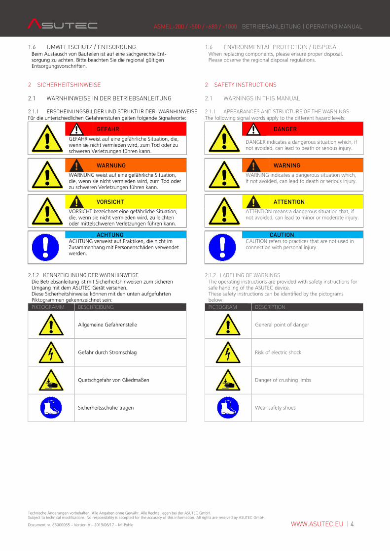
2.1.1 ERSCHEINUNGSBILDER UND STRUKTUR DER WARNHINWEISE 2.1.1 APPEARANCES AND STRUCTURE OF THE WARNINGS Für die unterschiedlichen Gefahrenstufen gelten folgende Signalworte: The following signal words apply to the different hazard levels:
GEFAHR
DANGER
GEFAHR weist auf eine gefährliche Situation, die, wenn sie nicht vermieden wird, zum Tod oder zu schweren Verletzungen führen kann.
DANGER indicates a dangerous situation which, if not avoided, can lead to death or serious injury.
WARNUNG
WARNING
WARNUNG weist auf eine gefährliche Situation, die, wenn sie nicht vermieden wird, zum Tod oder zu schweren Verletzungen führen kann.
WARNING indicates a dangerous situation which, if not avoided, can lead to death or serious injury.
VORSICHT
ATTENTION
VORSICHT bezeichnet eine gefährliche Situation, die, wenn sie nicht vermieden wird, zu leichten oder mittelschweren Verletzungen führen kann.
ATTENTION means a dangerous situation that, if not avoided, can lead to minor or moderate injury.
ACHTUNG
CAUTION ACHTUNG verweist auf Praktiken, die nicht im Zusammenhang mit Personenschäden verwendet werden.
CAUTION refers to practices that are not used in connection with personal injury.
2.1.2 KENNZEICHNUNG DER WARNHINWEISE 2.1.2 LABELING OF WARNINGS Die Betriebsanleitung ist mit Sicherheitshinweisen zum sicheren Umgang mit dem ASUTEC Gerät versehen. Diese Sicherheitshinweise können mit den unten aufgeführten Piktogrammen gekennzeichnet sein:
The operating instructions are provided with safety instructions for safe handling of the ASUTEC device. These safety instructions can be identified by the pictograms below:
PIKTOGRAMM BESCHREIBUNG PICTOGRAM DESCRIPTION
Allgemeine Gefahrenstelle
General point of danger
Gefahr durch Stromschlag
Risk of electric shock
Quetschgefahr von Gliedmaßen
Danger of crushing limbs
Sicherheitsschuhe tragen
Wear safety shoes
ASMEL-200 / -500 / -680 / -1000 BETRIEBSANLEITUNG | OPERATING MANUAL
Technische Änderungen vorbehalten. Alle Angaben ohne Gewähr. Alle Rechte liegen bei der ASUTEC GmbH. Subject to technical modifications. No responsibility is accepted for the accuracy of this information. All rights are reserved by ASUTEC GmbH.
Document nr. 85000065 – Version A – 2019/06/17 – M. Pohle WWW.ASUTEC.EU | 5
2.2 SICHERHEITSVORSCHRIFTEN FÜR DAS PERSONAL 2.2 SAFETY REGULATIONS FOR PERSONNEL
VORSICHT
ATTENTION
Jede Person, die mit der Montage, Inbetriebnahme, Bedienung und Instandhaltung des ASUTEC Geräts befasst ist, muss bevor sie die ersten Handgriffe ausführt, die komplette Betriebsanleitung und besonders das Kapitel "Sicherheitshinweise" gelesen und verstanden haben.
Every person involved in the installation, commissioning, operation and maintenance of the ASUTEC device must read and understand the entire operating instructions, especially the chapter "Safety instructions", before carrying out the first hand operation.
Die Durchführung dieser Arbeiten darf nur durch geschultes und eingewiesenes Fachpersonal erfolgen. Das Fachpersonal muss Erfahrung im Umgang mit pneumatischen und elektrischen Systemen besitzen. Das Fachpersonal muss mindestens 18 Jahre alt sind und körperlich, sowie geistig zum Bedienen des ASUTEC Geräts geeignet sein. Zu schulendes, anzulernendes, einzuweisendes oder im Rahmen einer allgemeinen Ausbildung befindliches Personal darf nur unter ständiger Aufsicht einer erfahrenen Person am ASUTEC Gerät tätig sein.
This work may only be carried out by trained and trained personnel. The personnel must have experience in handling pneumatic and electrical systems. The personnel must be at least 18 years old and physically and mentally able to operate the ASUTEC device. Personnel who are in general training or who are in instruction are only allowed to work on the ASUTEC device under the permanent supervision of an experienced person.
2.3 VORAUSSETZUNGEN FÜR DEN EINBAUORT 2.3 REQUIREMENTS FOR THE INSTALLATION LOCATION
GEFAHR
DANGER
Durch fehlerhafte elektrische Ausrüstung besteht die Gefahr eines Stromschlages, der schwere Verletzungen oder den Tod zur Folge haben kann. Elektrische Anschlüsse müssen den entsprechenden nationalen Sicherheitsvorschriften zur Betriebselektrik entsprechen. Nur Fachpersonal mit elektrischer/elektronischer Ausbildung darf an der elektrischen Ausrüstung arbeiten.
Faulty electrical equipment may result in a risk of electric shock which could result in serious injury or death. Electrical connections must comply with the relevant national safety regulations for the operational electrical system. Only electricians with electrical / electronic training are allowed to work on the electrical equipment.
WARNUNG
WARNING
Warnung vor unkontrollierten Bewegungen. Der Einbauort des ASUTEC Geräts muss den entsprechenden nationalen Sicherheitsvorschriften der Maschinensicherheit entsprechen.
Warning of uncontrolled movements. The installation location of the ASUTEC device must comply with the relevant national safety regulations for machine safety.
Am jeweiligen Einbauort müssen zusätzlich Warnhinweise für Quetschgefahren angebracht werden.
At the respective installation location, additional warning signs must be provided for crushing hazards.
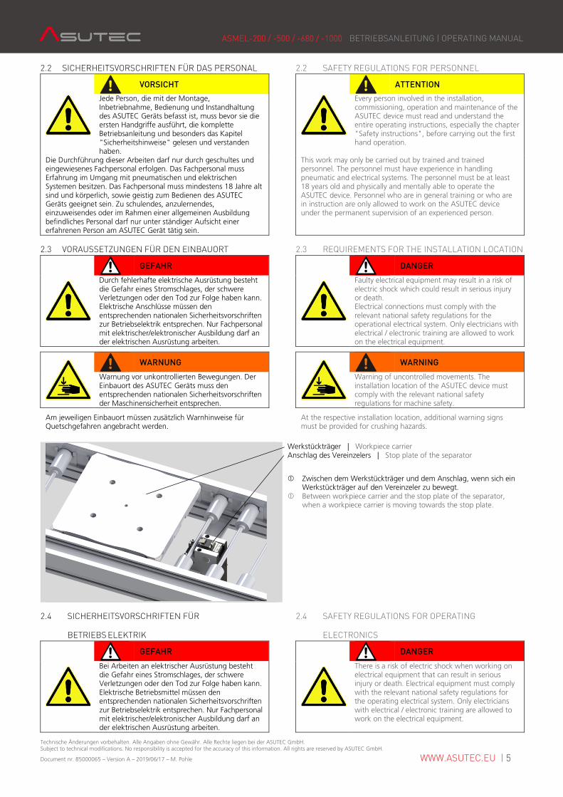
Werkstückträger | Workpiece carrier Anschlag des Vereinzelers | Stop plate of the separator
� Zwischen dem Werkstückträger und dem Anschlag, wenn sich ein Werkstückträger auf den Vereinzeler zu bewegt. � Between workpiece carrier and the stop plate of the separator, when a workpiece carrier is moving towards the stop plate.
2.4 SICHERHEITSVORSCHRIFTEN FÜR 2.4 SAFETY REGULATIONS FOR OPERATING
BETRIEBS ELEKTRIK ELECTRONICS
GEFAHR
DANGER
Bei Arbeiten an elektrischer Ausrüstung besteht die Gefahr eines Stromschlages, der schwere Verletzungen oder den Tod zur Folge haben kann. Elektrische Betriebsmittel müssen den entsprechenden nationalen Sicherheitsvorschriften zur Betriebselektrik entsprechen. Nur Fachpersonal mit elektrischer/elektronischer Ausbildung darf an der elektrischen Ausrüstung arbeiten.
There is a risk of electric shock when working on electrical equipment that can result in serious injury or death. Electrical equipment must comply with the relevant national safety regulations for the operating electrical system. Only electricians with electrical / electronic training are allowed to work on the electrical equipment.
ASMEL-200 / -500 / -680 / -1000 BETRIEBSANLEITUNG | OPERATING MANUAL
Technische Änderungen vorbehalten. Alle Angaben ohne Gewähr. Alle Rechte liegen bei der ASUTEC GmbH. Subject to technical modifications. No responsibility is accepted for the accuracy of this information. All rights are reserved by ASUTEC GmbH.
Document nr. 85000065 – Version A – 2019/06/17 – M. Pohle WWW.ASUTEC.EU | 6
3 TECHNISCHE DATEN 3 TECHNICAL DETAILS
3.1 AUSFÜHRUNG UND GEWICHT 3.1 EXECUTION AND WEIGHT Geräteausführung: Gehäuse aus Aluminium, Anschlag aus gehärtetem Stahl.
Gewicht der Geräte: ASMEL-200-EW-D09-I: 8,8 kg ASMEL-500-EW-D09-I: 8,85 kg ASMEL-680-EW-D09-I: 8,85 kg ASMEL-1000-EW-D09-I: 8,85 kg
Device design: Basic housing made of aluminum and stop plate made of hardened steel.
Weights of the devices: ASMEL-200-EW-D09-I: 8,8 kg ASMEL-500-EW-D09-I: 8,85 kg ASMEL-680-EW-D09-I: 8,85 kg ASMEL-1000-EW-D09-I: 8,85 kg
3.2 ARBEITSBEREICH 3.2 OPERATING RANGE
v = … [m/min]2) 9 12 15 18 24 30
ASMEL-200
Gewicht WT [kg]1)
Weight of WT [kg]1)
30 - 200 30 - 150 30 - 175 30 - 190 30 - 200 30 - 210
ASMEL-500 45 - 500 45 - 415 45 - 300 45 - 250 45 - 125 45 - 80
ASMEL-680 60 - 680 60 - 560 60 - 410 60 - 340 60 - 170 60 - 85
ASMEL-1000 80 - 1000 80 - 830 80 - 600 80 - 500 80 - 250 80 - 120 1) Minimal und maximal zu stoppende Massen. 2) Zulässige Fördergeschwindigkeit: Angaben gelten bei einer Fördermittelreibung von µ=0,07 zwischen Werkstückträger und Transferband und bei einem ASUTEC Standardanschlag aus Stahl. Generell wird von ASUTEC die Auslegung mit Hilfe des ASUTEC Online Produktfinders empfohlen.
1) Minimal and maximum masses to be stopped. 2) Permissible conveying speed: The information applies to a conveyor media friction of μ = 0.07 between workpiece carrier and conveyor media and with an ASUTEC standard stop plate made of steel. It is generally recommended to use the ASUTEC online product finder for choosing the suitable separator.
3.3 VORTRIEBSKRAFT 3.3 PROPULSIVE FORCE Um ein einwandfreies Absenken zu gewährleisten, dürfen die Vortriebskräfte nicht überschritten werden: 687 N Dieser Wert gilt bei dem ASUTEC-Standardanschlag aus Stahl und einer Stahl-Anschlagfläche am Werkstückträger.
In order to ensure a perfect lowering movement of the separator, the following propulsive forces must not be exceeded: 687 N This value applies to the ASUTEC standard steel stop plate and a steel stop surface at the workpiece carrier.
3.4 STAUDRUCK 3.4 RAM PRESSURE
ACHTUNG
CAUTION Wenn mehrere Werkstückträger in Transfersystemen aufgestaut und später vereinzelt werden, muss darauf geachtet werden, dass beim Freigeben des ersten Werkstückträgers, die Gesamtmasse der folgenden Werkstückträger das maximal zu stoppende Gewicht zu keiner Zeit überschreiten.
If several workpiece carriers in transfer systems get accumulated and get separated later, it must be ensured that when releasing the first workpiece carrier (WT) the total mass of the following work-piece carriers does not exceed the maximum weight to be stopped at any time.
Der maximale Staudruck ist abhängig von: - der Reibung zwischen WT und Transfersystem (Zahnriemen, Staurollenkette, Flachplattenkette, …) - der Reibung zwischen WT und Anschlag - der Position des WT Anschlags - den Umgebungsbedingungen (Staub, Anzahl der pneumatischen Verbraucher im System)
The maximal ram pressure depending on: - the friction between the WT and conveyor media (belt, accumulation roller chain, flat top chain, …) - the friction between the WT and stop plate - the position of the WT stop plate - the environmental conditions (Dust, pneumatic consumers in the system etc.)
3.5 ZYKLENZEITEN 3.5 CYCLE TIMES ASMEL-200 / -500 / -680 / -1000 ASMEL-200 / -500 / -680 / -1000 Minimale Zykluszeit1) 15 s Minimum cycle time1) 15 s 1) Die minimale Zylkluszeit basiert auf der Auslastung der Dämpfeinheit. Der bei den Vereinzelern verbaute Einfachhub-Steuermagnet hat eine Einschaltdauer von ED = 100 %.
1) The minimum cycle time is based on the utilization of the damping unit. The single-stroke solenoid, built into the separator, has a duty cycle of 100%.
3.6 FUNKTION 3.6 FUNCTION Die elektrischen Vereinzeler des Typs ASMEL-200 / -500 / -680 / -1000 sind gedämpfter Vereinzeler.
EW (Einfachwirkend): Das Absenken des Vereinzelers erfolgt durch elektrische Energie. Im stromlosen Zustand fährt der Vereinzeler durch eine Feder nach oben in die Sperrstellung und die nächsten Werkstückträger können gestoppt werden.
Die Dämpfung erfolgt durch eine selbsteinstellende hydraulische Dämpfeinheit.
Wenn ein Werkstückträger auf den Anschlag fährt, gedämpft wird und den Anschlag einfährt, so bleibt der Anschlag anschließend durch eine Sperre im eingefahrenen Zustand. Es wirkt keine Gegenkraft auf den Anschlag, die bewirken würde, dass der Anschlag ausfährt wenn zum Beispiel der Werkstückträger bei einer Bearbeitungsstation ausgehoben wird.
Das Ausfahren des Anschlags erfolgt in der unteren Absenkposition des Vereinzelers durch die Rückstellkraft der hydraulischen Dämpfeinheit.
The electrical separators ASMEL-200 / -500 / -680 / -1000 are separators with damping.
EW (single-acting): The lowering of the separator is done by electric energy. In de-energized state, the separator moves upwards into the blocking position by a spring and the next workpiece carriers can be stopped. The damping is done by a self-adjusting hydraulic damping unit.
If a workpiece carrier moves to the stop, is damped and push the stop plate all the way in, then the stop plate remains in the retracted (damped) position by a lock. There is no counterforce on the stop, which would cause the stop plate extends when, for example, the workpiece carrier is lifted at a processing station and no workpiece carrier is pushing against the stop plate.
The extension of the stop takes place in the lower lowering position of the separator by the restoring force of the hydraulic damping unit.
ASMEL-200 / -500 / -680 / -1000 BETRIEBSANLEITUNG | OPERATING MANUAL
Technische Änderungen vorbehalten. Alle Angaben ohne Gewähr. Alle Rechte liegen bei der ASUTEC GmbH. Subject to technical modifications. No responsibility is accepted for the accuracy of this information. All rights are reserved by ASUTEC GmbH.
Document nr. 85000065 – Version A – 2019/06/17 – M. Pohle WWW.ASUTEC.EU | 7
3.7 ELEKTRISCHER ANSCHLUSS 3.7 ELECTRICAL CONNECTION Gerätesteckdose nach DIN EN 175301-803, Form A Zum Schutz Ihrer Steuerung empfehlen wir eine geeignete Freilaufdiode oder einen geeigneten Varistor parallel zum Vereinzeler zu schalten.
Connector according to DIN EN 175301-803, form A For the safety for your control unit we recommend a suitable flyback diode or a suitable varistor parallel to the separating stop.
3.8 ELEKTRISCHE DATEN 3.8 ELECTRICAL DATA Spannung: 24 V Einschaltdauer: 100 % Stromaufnahme: 1,82 A
Voltage: 24 V Duty cycle: 100 % Current consumption: 1.82 A
3.9 TEMPERATURBEREICH 3.8 TEMPERATURE RANGE Temperaturbereich: + 5°C bis + 60°C (ohne Zubehör) Temperature range: + 5°C, up to + 60°C (without accessories)
4 TRANSPORT 4 TRANSPORT
VORSICHT
ATTENTION
Der Vereinzeler wird von Hand transportiert. Tragen Sie beim Transport Sicherheitsschuhe.
The separator is transported by hand. Wear safety shoes during transport.
5 MONTAGE 5 INSTALLATION
5.1 SICHERHEIT BEI DER MONTAGE 5.1 SAFETY FOR INSTALLATION
WARNUNG
WARNING
Warnung vor unkontrollierten Bewegungen. Während der Vereinzeler an einer Energiequelle angeschlossen ist, kann er unkontrollierte Bewegungen ausführen. Vor Montagearbeiten müssen Sie die elektrischen und pneumatischen Energiezuführungen abschalten und ein unbeabsichtigtes Wiedereinschalten verhindern, z. B. Hauptschalter der Gesamtmaschine abschließen und ein entsprechendes Warnschild anbringen.
While the separator is connected to an energy source, it can perform uncontrolled movements. Before starting the installation work, you must switch off the electrical and pneumatic power supply and prevent unintentional restarting. For example, switch off the entire machine on the main switch and lock the switch against re-activation. Attach an appropriate warning sign.
GEFAHR
DANGER
Durch fehlerhafte elektrische Montage besteht die Gefahr eines Stromschlages, der schwere Verletzungen oder den Tod zur Folge haben kann. Nur Fachpersonal mit elektrischer / elektronischer Ausbildung darf an der elektrischen Ausrüstung Arbeiten.
Faulty electrical installation may result in a risk of electric shock which can result in serious injury or death. Only electricians with electrical / electronic training may work on electrical equipment.
5.2 MONTAGE AM EINSATZORT 5.2 INSTALLATION AT THE PLACE OF USE
ACHTUNG
CAUTION Befestigungselemente sind im Lieferumfang nicht enthalten und müssen getrennt beschafft werden. Die Befestigung erfolgt mit 4 Schrauben M10. Je nach Ausführung der Quertraverse, auf die der Vereinzeler geschraubt wird, ergibt sich wie auf der Zeichnung in Kapitel 5.4 ersichtlich, eine zu verwendete Schraubenlänge von 70 mm. Das Anzugsmoment beträgt jeweils 40 Nm.
Fastening elements are not included in the scope of delivery and must be procured separately. The attachment is made with 4 screws M10. Depending on the design of the crossbeam, on which the separator is screwed, the result is a screw length of 70 mm to be used, as shown in the drawing in chapter 5.4. The tightening torque is 40 Nm each.
ASMEL-200 / -500 / -680 / -1000 BETRIEBSANLEITUNG | OPERATING MANUAL
Technische Änderungen vorbehalten. Alle Angaben ohne Gewähr. Alle Rechte liegen bei der ASUTEC GmbH. Subject to technical modifications. No responsibility is accepted for the accuracy of this information. All rights are reserved by ASUTEC GmbH.
Document nr. 85000065 – Version A – 2019/06/17 – M. Pohle WWW.ASUTEC.EU | 8
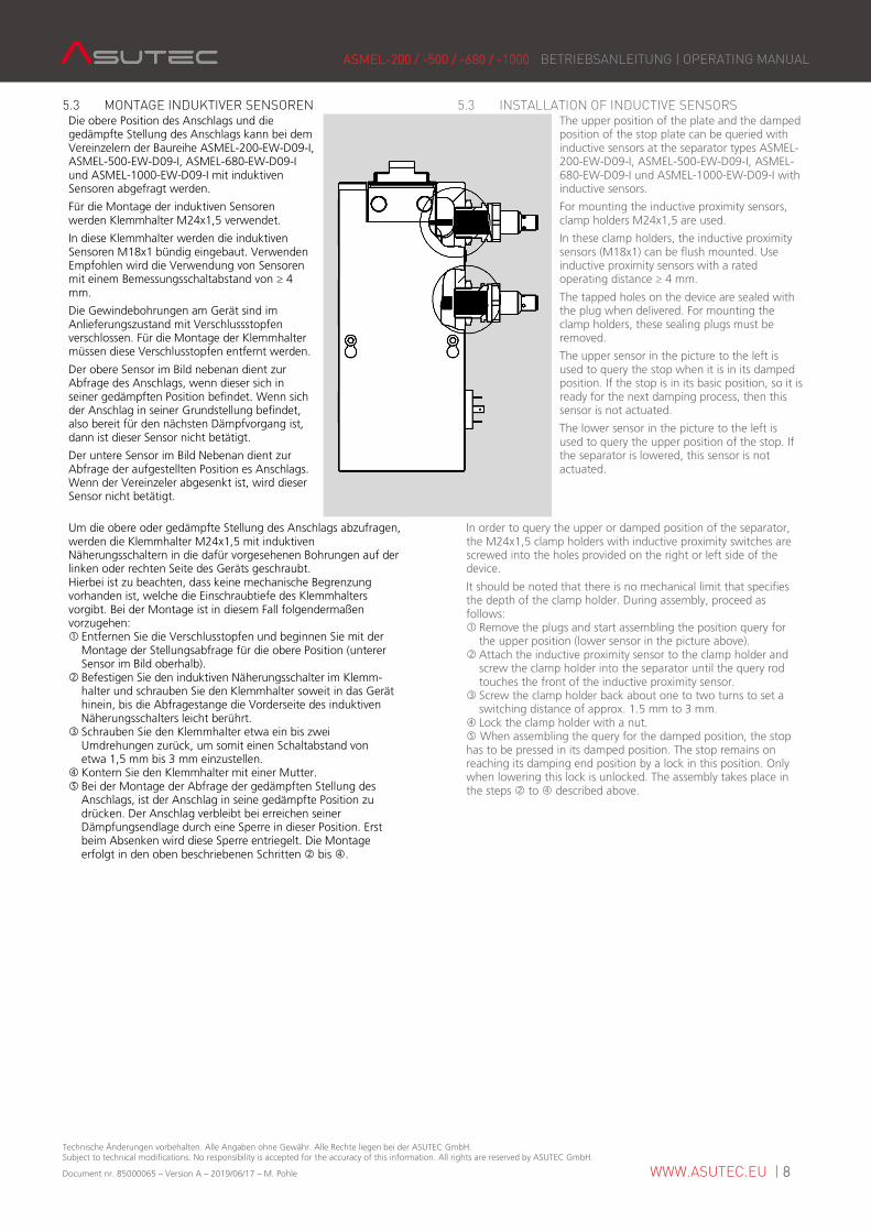
5.3 MONTAGE INDUKTIVER SENSOREN 5.3 INSTALLATION OF INDUCTIVE SENSORS Die obere Position des Anschlags und die gedämpfte Stellung des Anschlags kann bei dem Vereinzelern der Baureihe ASMEL-200-EW-D09-I, ASMEL-500-EW-D09-I, ASMEL-680-EW-D09-I und ASMEL-1000-EW-D09-I mit induktiven Sensoren abgefragt werden.
Für die Montage der induktiven Sensoren werden Klemmhalter M24x1,5 verwendet.
In diese Klemmhalter werden die induktiven Sensoren M18x1 bündig eingebaut. Verwenden Empfohlen wird die Verwendung von Sensoren mit einem Bemessungsschaltabstand von ≥ 4 mm.
Die Gewindebohrungen am Gerät sind im Anlieferungszustand mit Verschlussstopfen verschlossen. Für die Montage der Klemmhalter müssen diese Verschlusstopfen entfernt werden.
Der obere Sensor im Bild nebenan dient zur Abfrage des Anschlags, wenn dieser sich in seiner gedämpften Position befindet. Wenn sich der Anschlag in seiner Grundstellung befindet, also bereit für den nächsten Dämpfvorgang ist, dann ist dieser Sensor nicht betätigt.
Der untere Sensor im Bild Nebenan dient zur Abfrage der aufgestellten Position es Anschlags. Wenn der Vereinzeler abgesenkt ist, wird dieser Sensor nicht betätigt.
The upper position of the plate and the damped position of the stop plate can be queried with inductive sensors at the separator types ASMEL-200-EW-D09-I, ASMEL-500-EW-D09-I, ASMEL-680-EW-D09-I und ASMEL-1000-EW-D09-I with inductive sensors.
For mounting the inductive proximity sensors, clamp holders M24x1,5 are used.
In these clamp holders, the inductive proximity sensors (M18x1) can be flush mounted. Use inductive proximity sensors with a rated operating distance ≥ 4 mm.
The tapped holes on the device are sealed with the plug when delivered. For mounting the clamp holders, these sealing plugs must be removed.
The upper sensor in the picture to the left is used to query the stop when it is in its damped position. If the stop is in its basic position, so it is ready for the next damping process, then this sensor is not actuated.
The lower sensor in the picture to the left is used to query the upper position of the stop. If the separator is lowered, this sensor is not actuated.
Um die obere oder gedämpfte Stellung des Anschlags abzufragen, werden die Klemmhalter M24x1,5 mit induktiven Näherungsschaltern in die dafür vorgesehenen Bohrungen auf der linken oder rechten Seite des Geräts geschraubt. Hierbei ist zu beachten, dass keine mechanische Begrenzung vorhanden ist, welche die Einschraubtiefe des Klemmhalters vorgibt. Bei der Montage ist in diesem Fall folgendermaßen vorzugehen: � Entfernen Sie die Verschlusstopfen und beginnen Sie mit der Montage der Stellungsabfrage für die obere Position (unterer Sensor im Bild oberhalb). � Befestigen Sie den induktiven Näherungsschalter im Klemm- halter und schrauben Sie den Klemmhalter soweit in das Gerät hinein, bis die Abfragestange die Vorderseite des induktiven Näherungsschalters leicht berührt. � Schrauben Sie den Klemmhalter etwa ein bis zwei Umdrehungen zurück, um somit einen Schaltabstand von etwa 1,5 mm bis 3 mm einzustellen. � Kontern Sie den Klemmhalter mit einer Mutter. � Bei der Montage der Abfrage der gedämpften Stellung des Anschlags, ist der Anschlag in seine gedämpfte Position zu drücken. Der Anschlag verbleibt bei erreichen seiner Dämpfungsendlage durch eine Sperre in dieser Position. Erst beim Absenken wird diese Sperre entriegelt. Die Montage erfolgt in den oben beschriebenen Schritten � bis �.
In order to query the upper or damped position of the separator, the M24x1,5 clamp holders with inductive proximity switches are screwed into the holes provided on the right or left side of the device.
It should be noted that there is no mechanical limit that specifies the depth of the clamp holder. During assembly, proceed as follows: � Remove the plugs and start assembling the position query for the upper position (lower sensor in the picture above). � Attach the inductive proximity sensor to the clamp holder and screw the clamp holder into the separator until the query rod touches the front of the inductive proximity sensor. � Screw the clamp holder back about one to two turns to set a switching distance of approx. 1.5 mm to 3 mm. � Lock the clamp holder with a nut. � When assembling the query for the damped position, the stop has to be pressed in its damped position. The stop remains on reaching its damping end position by a lock in this position. Only when lowering this lock is unlocked. The assembly takes place in the steps � to � described above.
ASMEL-200 / -500 / -680 / -1000 BETRIEBSANLEITUNG | OPERATING MANUAL
Technische Änderungen vorbehalten. Alle Angaben ohne Gewähr. Alle Rechte liegen bei der ASUTEC GmbH. Subject to technical modifications. No responsibility is accepted for the accuracy of this information. All rights are reserved by ASUTEC GmbH.
Document nr. 85000065 – Version A – 2019/06/17 – M. Pohle WWW.ASUTEC.EU | 9
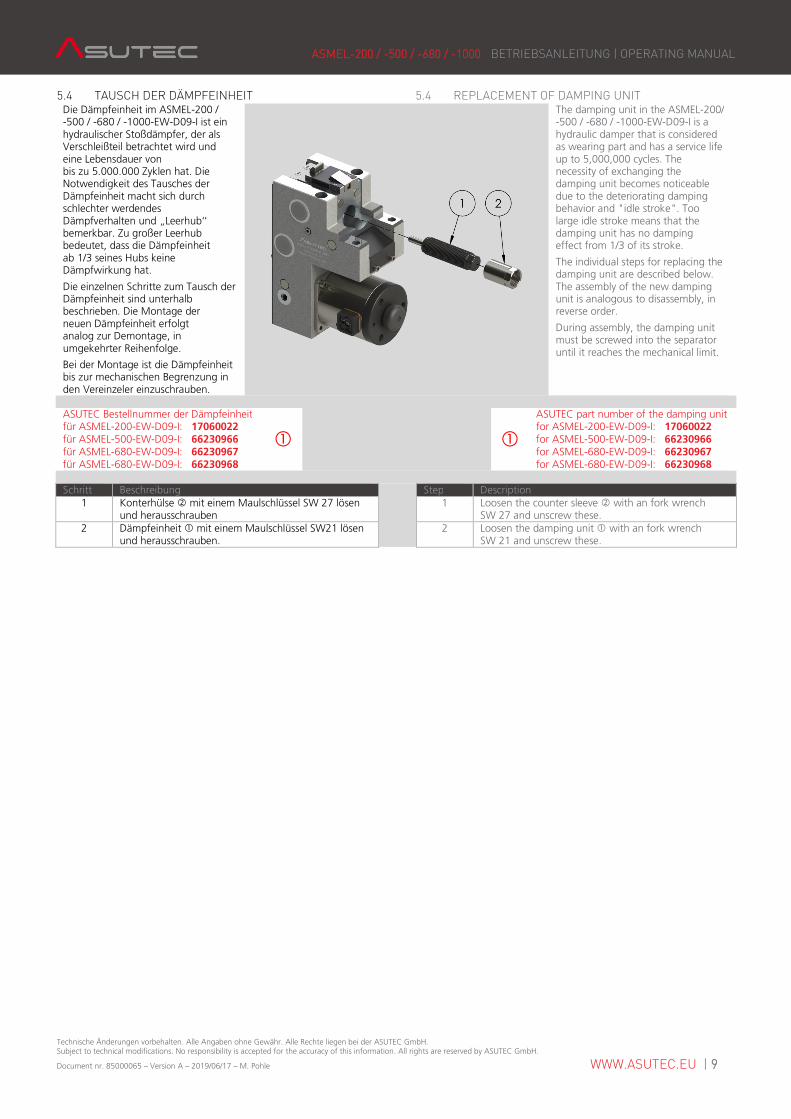
5.4 TAUSCH DER DÄMPFEINHEIT 5.4 REPLACEMENT OF DAMPING UNIT Die Dämpfeinheit im ASMEL-200 / -500 / -680 / -1000-EW-D09-I ist ein hydraulischer Stoßdämpfer, der als Verschleißteil betrachtet wird und eine Lebensdauer von bis zu 5.000.000 Zyklen hat. Die Notwendigkeit des Tausches der Dämpfeinheit macht sich durch schlechter werdendes Dämpfverhalten und „Leerhub‘‘ bemerkbar. Zu großer Leerhub bedeutet, dass die Dämpfeinheit ab 1/3 seines Hubs keine Dämpfwirkung hat.
Die einzelnen Schritte zum Tausch der Dämpfeinheit sind unterhalb beschrieben. Die Montage der neuen Dämpfeinheit erfolgt analog zur Demontage, in umgekehrter Reihenfolge.
Bei der Montage ist die Dämpfeinheit bis zur mechanischen Begrenzung in den Vereinzeler einzuschrauben.
The damping unit in the ASMEL-200/ -500 / -680 / -1000-EW-D09-I is a hydraulic damper that is considered as wearing part and has a service life up to 5,000,000 cycles. The necessity of exchanging the damping unit becomes noticeable due to the deteriorating damping behavior and "idle stroke". Too large idle stroke means that the damping unit has no damping effect from 1/3 of its stroke.
The individual steps for replacing the damping unit are described below. The assembly of the new damping unit is analogous to disassembly, in reverse order.
During assembly, the damping unit must be screwed into the separator until it reaches the mechanical limit.
ASUTEC Bestellnummer der Dämpfeinheit für ASMEL-200-EW-D09-I: 17060022 für ASMEL-500-EW-D09-I: 66230966 für ASMEL-680-EW-D09-I: 66230967 für ASMEL-680-EW-D09-I: 66230968
�
� ASUTEC part number of the damping unit for ASMEL-200-EW-D09-I: 17060022 for ASMEL-500-EW-D09-I: 66230966 for ASMEL-680-EW-D09-I: 66230967 for ASMEL-680-EW-D09-I: 66230968
Schritt Beschreibung Step Description
1 Konterhülse � mit einem Maulschlüssel SW 27 lösen und herausschrauben
1 Loosen the counter sleeve � with an fork wrench SW 27 and unscrew these.
2 Dämpfeinheit � mit einem Maulschlüssel SW21 lösen und herausschrauben.
2 Loosen the damping unit � with an fork wrench SW 21 and unscrew these.
ASMEL-200 / -500 / -680 / -1000 BETRIEBSANLEITUNG | OPERATING MANUAL
Technische Änderungen vorbehalten. Alle Angaben ohne Gewähr. Alle Rechte liegen bei der ASUTEC GmbH. Subject to technical modifications. No responsibility is accepted for the accuracy of this information. All rights are reserved by ASUTEC GmbH.
Document nr. 85000065 – Version A – 2019/06/17 – M. Pohle WWW.ASUTEC.EU | 10
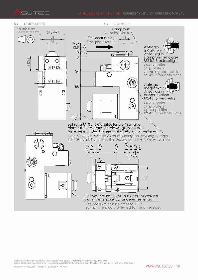
5.4 ABMESSUNGEN 5.4 DIMENSIONS
ASMEL-200 / -500 / -680 / -1000 BETRIEBSANLEITUNG | OPERATING MANUAL
Technische Änderungen vorbehalten. Alle Angaben ohne Gewähr. Alle Rechte liegen bei der ASUTEC GmbH. Subject to technical modifications. No responsibility is accepted for the accuracy of this information. All rights are reserved by ASUTEC GmbH.
Document nr. 85000065 – Version A – 2019/06/17 – M. Pohle WWW.ASUTEC.EU | 11
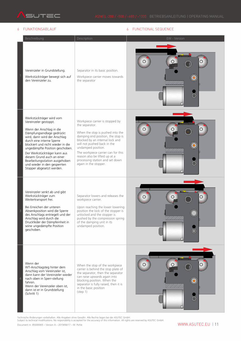
6 FUNKTIONSABLAUF 6 FUNCTIONAL SEQUENCE
Beschreibung Description EW - Version
1
Vereinzeler in Grundstellung.
Werkstückträger bewegt sich auf den Vereinzeler zu.
Separator in its basic position.
Workpiece carrier moves towards the separator
2
Werkstückträger wird vom Vereinzeler gestoppt. Wenn der Anschlag in die Dämpfungsendlage gedrückt wird, dann wird der Anschlag durch eine interne Sperre blockiert und nicht wieder in die ungedämpfte Position geschoben.
Der Werkstückträger kann aus diesem Grund auch an einer Bearbeitungsstation ausgehoben und wieder in den gesperrten Stopper abgesetzt werden.
Workpiece carrier is stopped by the separator. When the stop is pushed into the damping end position, the stop is blocked by an internal lock and will not pushed back in the undamped position.
The workpiece carrier can for this reason also be lifted up at a processing station and set down again in the stopper.
3
Vereinzeler senkt ab und gibt Werkstückträger zum Weitertransport frei. Bei Erreichen der unteren Absenkposition wird die Sperre des Anschlags entriegelt und der Anschlag wird durch die Druckfeder der Dämpfeinheit in seine ungedämpfte Position geschoben.
Separator lowers and releases the workpiece carrier. Upon reaching the lower lowering position the lock of the stopper is unlocked and the stopper is pushed by the compression spring of the damping unit in its undamped position.
4
Wenn der WT-Anschlagsteg hinter dem Anschlag vom Vereinzeler ist, dann kann der Vereinzeler wieder nach oben in Sperr-stellung fahren. Wenn der Vereinzeler oben ist, dann ist er in Grundstellung (Schritt 1)
When the stop of the workpiece carrier is behind the stop plate of the separator, then the separator can raise upwards again into blocking position. When the separator is fully raised, then it is in the basic position (step 1)
ASMEL-200 / -500 / -680 / -1000 BETRIEBSANLEITUNG | OPERATING MANUAL
Technische Änderungen vorbehalten. Alle Angaben ohne Gewähr. Alle Rechte liegen bei der ASUTEC GmbH. Subject to technical modifications. No responsibility is accepted for the accuracy of this information. All rights are reserved by ASUTEC GmbH.
Document nr. 85000065 – Version A – 2019/06/17 – M. Pohle WWW.ASUTEC.EU | 12
7 WARTUNG 7 MAINTENANCE
7.1 SICHERHEIT BEI DER WARTUNG 7.1 SAFETY DURING MAINTENANCE
WARNUNG
WARNING
Warnung vor unkontrollierten Bewegungen. Während der Vereinzeler an einer Energiequelle angeschlossen ist, kann er unkontrollierte Bewegungen ausführen. Vor Montagearbeiten müssen Sie die elektrischen und pneumatischen Energiezuführungen abschalten und ein unbeabsichtigtes Wiedereinschalten verhindern, z. B. Hauptschalter der Gesamtmaschine abschließen und ein entsprechendes Warnschild anbringen.
While the separator is connected to an energy source, it can perform uncontrolled movements. Before starting the installation work, you must switch off the electrical and pneumatic power supply and prevent unintentional restarting. For example, switch off the entire machine on the main switch and lock the switch against re-activation. Attach an appropriate warning sign.
GEFAHR
DANGER
Gefahr durch Wasser in der Elektrik! Bauteile nur mit einem feuchten Lappen abreiben. Wasser darf nicht über den Vereinzeler fließen oder tropfen. Wasser kann in die Elektronikkomponenten eindringen. Tod durch Stromschlag kann die Folge sein.
Danger by water in the electrics! Only rub the components with a damp cloth. Water must not flow or drip over the separator. Water can penetrate into the electronic components. Death by electric shock can be the result.
7.2 WARTUNGSARBEITEN 7.2 MAINTENANCE WORK Das Gerät ist Wartungsfrei. Reinigen Sie den Vereinzeler und dessen Einsatzumgebung je nach Verschmutzungsgrad. Der Bereich um den Anschlag muss sauber und frei von Spänen sein, um ein exaktes Positionieren des Werkstückträgers gewährleisten zu können.
The device is maintenance-free. Clean the separator and its surrounding environment depending on the degree of soiling. The area around the stop plate must be clean and free from chips in order to ensure precise positioning of the workpiece carrier.
ASMEL-200 / -500 / -680 / -1000 BETRIEBSANLEITUNG | OPERATING MANUAL
Technische Änderungen vorbehalten. Alle Angaben ohne Gewähr. Alle Rechte liegen bei der ASUTEC GmbH. Subject to technical modifications. No responsibility is accepted for the accuracy of this information. All rights are reserved by ASUTEC GmbH.
Document nr. 85000065 – Version A – 2019/06/17 – M. Pohle WWW.ASUTEC.EU | 13
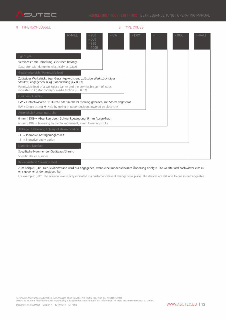
8 TYPENSCHLÜSSEL 8 TYPE CODES
ASMEL - 200 - 500 - 680 - 1000
- EW - D09 - I - XXX (-Ref.)
Typ / Type
Vereinzeler mit Dämpfung, elektrisch betätigt
Separator with damping, electrically actuated
Gewichtsbereich / Permissible load
Zulässiges Werkstückträger Gesamtgewicht und zulässige Werkstückträger Staulast, angegeben in kg (Bandreibung µ = 0,07)
Permissible load of a workpiece carrier and the permissible sum of loads, indicated in kg (for conveyor media friction μ = 0.07)
Funktion / Function
EW = Einfachwirkend � Durch Feder in oberer Stellung gehalten, mit Storm abgesenkt
EW = Single acting � Held by spring in upper position, lowered by electricity
Absenkhub / Lowering stroke
(in mm) D09 = Absenken durch Schwenkbewegung, 9 mm Absenkhub
(in mm) D09 = Lowering by pivotal movement, 9 mm lowering stroke
Abfrage Hubstellung / Query of stroke position
- I = Induktive Abfragemöglichkeit
- I = Inductive query option
Nummer / Number
Spezifische Nummer der Geräteausführung
Specific device number
Revisionsstand / Revision level
Zum Beispiel „-B“. Der Revisionsstand wird nur angegeben, wenn eine kundenrelevante Änderung erfolgte. Die Geräte sind nachwievor eins zu eins gegeneinander austauschbar.
For example: „-B“. The revision level is only indicated if a customer-relevant change took place. The devices are still one to one interchangeable.
ASMEL-200 / -500 / -680 / -1000 BETRIEBSANLEITUNG | OPERATING MANUAL
Technische Änderungen vorbehalten. Alle Angaben ohne Gewähr. Alle Rechte liegen bei der ASUTEC GmbH. Subject to technical modifications. No responsibility is accepted for the accuracy of this information. All rights are reserved by ASUTEC GmbH.
Document nr. 85000065 – Version A – 2019/06/17 – M. Pohle WWW.ASUTEC.EU | 14
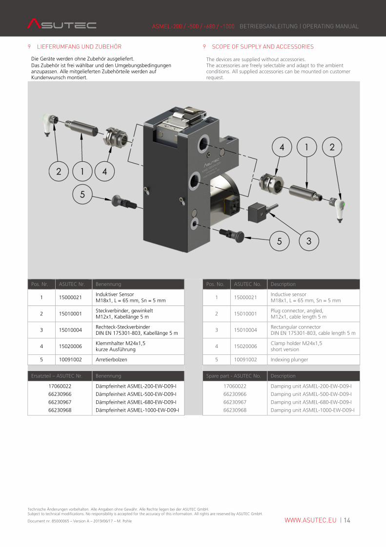
9 LIEFERUMFANG UND ZUBEHÖR 9 SCOPE OF SUPPLY AND ACCESSORIES
Die Geräte werden ohne Zubehör ausgeliefert. Das Zubehör ist frei wählbar und den Umgebungsbedingungen anzupassen. Alle mitgelieferten Zubehörteile werden auf Kundenwunsch montiert.
The devices are supplied without accessories. The accessories are freely selectable and adapt to the ambient conditions. All supplied accessories can be mounted on customer request.
Pos. Nr. ASUTEC Nr. Benennung Pos. No. ASUTEC No. Description
1 15000021 Induktiver Sensor M18x1, L = 65 mm, Sn = 5 mm
1 15000021 Inductive sensor M18x1, L = 65 mm, Sn = 5 mm
2 15010001 Steckverbinder, gewinkelt M12x1, Kabellänge 5 m
2 15010001 Plug connector, angled, M12x1, cable length 5 m
3 15010004 Rechteck-Steckverbinder DIN EN 175301-803, Kabellänge 5 m
3 15010004 Rectangular connector DIN EN 175301-803, cable length 5 m
4 15020006 Klemmhalter M24x1,5 kurze Ausführung
4 15020006 Clamp holder M24x1,5 short version
5 10091002 Arretierbolzen 5 10091002 Indexing plunger
Ersatzteil – ASUTEC Nr. Benennung Spare part - ASUTEC No. Description
17060022
66230966
66230967
66230968
Dämpfeinheit ASMEL-200-EW-D09-I
Dämpfeinheit ASMEL-500-EW-D09-I
Dämpfeinheit ASMEL-680-EW-D09-I
Dämpfeinheit ASMEL-1000-EW-D09-I
17060022
66230966
66230967
66230968
Damping unit ASMEL-200-EW-D09-I
Damping unit ASMEL-500-EW-D09-I
Damping unit ASMEL-680-EW-D09-I
Damping unit ASMEL-1000-EW-D09-I
ASMEL-200 / -500 / -680 / -1000 BETRIEBSANLEITUNG | OPERATING MANUAL
Technische Änderungen vorbehalten. Alle Angaben ohne Gewähr. Alle Rechte liegen bei der ASUTEC GmbH. Subject to technical modifications. No responsibility is accepted for the accuracy of this information. All rights are reserved by ASUTEC GmbH.
Document nr. 85000065 – Version A – 2019/06/17 – M. Pohle WWW.ASUTEC.EU | 15
10 EINBAUERKLÄRUNG 10 COPY OF THE DECLARATION OF INCORPORATION
Original der Erklärung für den Einbau einer unvollständigen Maschine im Sinne der EG Richtlinie Maschinen 2006/42/EG Anhang II 1 B. Typen: ASMEL-200, ASMEL-500, ASMEL-680, ASMEL-800, ASMEL-1000 Typenbezeichnung: Vereinzeler mit Dämpfung, elektrisch, mit Elektromagnet Fortlaufende Serien-Nr.: 1079 Die Maschine entspricht den einschlägigen Bestimmungen der:
- EG-Richtlinie 2006/42/EG Amtsblatt L157/24 Hersteller und Bevollmächtigter für die Zusammenstellung der relevanten technischen Unterlagen gemäß Anhang VII B: Asutec GmbH Küferstraße 11 73257 Köngen Folgende grundlegenden Anforderungen kommen zur Anwendung, soweit es im Rahmen des Lieferumfanges möglich ist: 2006/42/EG, Anhang I, allgemeine Grundsätze; 2006/42/EG, Anhang I 1, grundlegende Sicherheits- und Gesundheitsanforderungen Die speziellen Unterlagen, entsprechend EG-Richtlinie 2006/42/EG Anhang VII Teil B, werden auf begründetes Verlangen einzelstaatlichen Stellen per Post/E-Mail übermittelt. Angewandte Normen: DIN EN ISO 12100 Sicherheit von Maschinen, allgemeine Gestaltungsleitsätze 2011-3 Die Inbetriebnahme dieser Maschine/des Maschinenteils ist so lange untersagt, bis festgestellt wurde, dass die Maschine, in die sie eingebaut werden soll, den Bestimmungen den anwendbaren EG-Richtlinien, sowie den harmonisierten Normen, Europanormen oder den entsprechenden nationalen Normen entspricht.
Köngen, 03.03.2017 Manfred Mattersberger
Copy of the declaration of incorporation for partly complete machinery in the sense of the EC-directive for machines 2016/42/EC Annex II 1B. Types: ASMEL-200, ASMEL-500, ASMEL-680, ASMEL-800, ASMEL-1000 Type designation: Separator with damping, electrically, with Solenoid Continuous serial no.: 1079 The machine complies with the relevant provisions of the:
- EC Directive 2006/42 / EC Official Journal L157 / 24 Manufacturer and authorized representative for the compilation of the relevant technical documentation in accordance with Annex VII B: Asutec GmbH Küferstraße 11 73257 Köngen The following essential requirements are applied as far as is possible within the scope of supply: 2006/42 / EC, Annex I, general principles; 2006/42 / EC, Annex I 1, basic health and safety requirements The special documents, according to EC Directive 2006/42 / EC Annex VII, Part B shall be transmitted national authorities by post / email to a reasoned request. Applied standards: DIN EN ISO 12100 Safety of machinery, General design guidelines 2011-3 The commissioning of this machine / machine part is prohibited until it is determined that the machine in which it is to be installed complies with the applicable EC directives as well as the harmonized standards, European standards or the corresponding national standards.
Ort, Datum Name / Unterschrift Geschäftsführer