Embed Size (px)
Citation preview
Professional Series Network Thermostat Configuration Guide(NT100e/h, NT120e/h, NT130e/h, NT150e/h, and NT160)Release 3.0
Part No. 600-01000-200, Rev. 2August 2007
Inside ...
Configuring the thermostat using the TDIConfiguring the thermostat using the TMITroubleshooting
Beta Draft Confidential
ii Professional Series Network Thermostat Configuration Guide, Release 3.0Part No. 600-01000-200, Rev. 2
Copyright
Copyright © 2007 Proliphix, Inc. All Rights Reserved.
The following are trademarks of Proliphix, Inc.:
All other trademarks are the property of their respective owners.
This document contains information that is the property of Proliphix, Inc. This document may not be copied, reproduced, reduced to any electronic medium or machine readable form, or otherwise duplicated, and the information herein may not be used, disseminated or otherwise disclosed, except with the prior written consent of Proliphix, Inc.

Beta Draft ConfidentialSoftware License Agreement
Professional Series Network Thermostat Configuration Guide, Release 3.0 iiiPart No. 600-01000-200, Rev. 2
License for Use of Proliphix Software
IMPORTANT NOTICE -- READ CAREFULLY: This License For Customer Use of the Proliphix Remote Management Interface Software ("PROLIPHIX LICENSE") is the agreement which governs use of the software of Proliphix Incorporated and its subsidiaries ("Proliphix") downloadable here from, including computer software and associated printed materials ("PROLIPHIX SOFTWARE"). By downloading, installing, or otherwise using the PROLIPHIX SOFTWARE, you agree to be bound by the terms of this PROLIPHIX LICENSE. If you do not agree to the terms of this PROLIPHIX LICENSE, do not download or run the PROLIPHIX SOFTWARE.
RECITALS Use of Proliphix's products requires four elements: the Thermostat, the Thermostat FIRMWARE, the Proliphix Remote Management Software and a personal computer. The PROLIPHIX SOFTWARE is protected by copyright laws and international copyright treaties, as well as other intellectual property laws and treaties. This PROLIPHIX LICENSE sets forth the terms and conditions of the SOFTWARE LICENSE only.
DEFINITIONS Customer. Customer means the entity or individual that uses the SOFTWARE.
GRANT OF LICENSE
Rights and Limitations of Grant. Proliphix hereby grants Customer the following non-exclusive, non-transferable right to use the SOFTWARE, with the following limitations:
Rights. Customer may use the SOFTWARE on one or more computers, and may not otherwise copy the SOFTWARE. This PROLIPHIX LICENSE of SOFTWARE may be used concurrently on different computers.
LIMITATIONS No Reverse Engineering. Customer may not reverse engineer, decompile, or disassemble the SOFTWARE, nor attempt in any other manner to obtain the source code.
No Separation of Components. The SOFTWARE is licensed as a single product. Its component parts may not be separated for use on more than one computer, nor otherwise used separately from the other parts.
No Rental. Customer may not rent or lease the SOFTWARE to someone else.
TERMINATION This LICENSE will automatically terminate if Customer fails to comply with any of the terms and conditions hereof. In such event, Customer will be prohibited from access to the SOFTWARE by termination of Customer’s Remote Management Interface account.
Defensive Suspension. If Customer commences or participates in any legal proceeding against Proliphix, then Proliphix may, in its sole discretion, suspend or terminate all license grants and any other rights provided under this LICENSE during the pendency of such legal proceedings.
COPYRIGHT All title and copyrights in and to the SOFTWARE (including but not limited to all images, photographs, animations, video, audio, music, text, and other information incorporated into the SOFTWARE), the accompanying printed materials, and any copies of the SOFTWARE, are owned by Proliphix, or its suppliers. The SOFTWARE is protected by copyright laws and international treaty provisions. Accordingly, Customer is required to treat the SOFTWARE like any other copyrighted material, except as otherwise allowed pursuant to this LICENSE and that it may make one copy of the SOFTWARE solely for backup or archive purposes.
APPLICABLE LAW
This LICENSE shall be deemed to have been made in, and shall be construed pursuant to, the laws of the Commonwealth of Massachusetts. The United Nations Convention on Contracts for the International Sale of Goods is specifically disclaimed.
Beta Draft Confidential
iv Professional Series Network Thermostat Configuration Guide, Release 3.0Part No. 600-01000-200, Rev. 2
Software License Agreement
DISCLAIMER OF WARRANTIES AND LIMITATION ON LIABILITY
No Warranties. TO THE MAXIMUM EXTENT PERMITTED BY APPLICABLE LAW, THE SOFTWARE IS PROVIDED "AS IS" AND PROLIPHIX AND ITS SUPPLIERS DISCLAIM ALL WARRANTIES, EITHER EXPRESSED OR IMPLIED, INCLUDING, BUT NOT LIMITED TO, IMPLIED WARRANTIES OF MERCHANTABILITY AND FITNESS FOR A PARTICULAR PURPOSE.
No Liability for Consequential Damages. TO THE MAXIMUM EXTENT PERMITTED BY APPLICABLE LAW, IN NO EVENT SHALL PROLIPHIX OR ITS SUPPLIERS BE LIABLE FOR ANY SPECIAL, INCIDENTAL, INDIRECT, OR CONSEQUENTIAL DAMAGES WHATSOEVER (INCLUDING, WITHOUT LIMITATION, DAMAGES FOR LOSS OF BUSINESS PROFITS, BUSINESS INTERRUPTION, LOSS OF BUSINESS INFORMATION, OR ANY OTHER PECUNIARY LOSS) ARISING OUT OF THE USE OF OR INABILITY TO USE THE SOFTWARE,EVEN IF PROLIPHIX HAS BEEN ADVISED OF THE POSSIBILITY OF SUCH DAMAGES.
OTHER If any provision of this LICENSE is inconsistent with, or cannot be fully enforced under, the law, such provision will be construed as limited to the extent necessary to be consistent with and fully enforceable under the law. This LICENSE is the final, complete and exclusive agreement between the parties relating to the subject matter hereof, and supersedes all prior or contemporaneous understandings and agreements relating to such subject matter, whether oral or written. This LICENSE may only be modified in writing signed by an authorized officer of Proliphix. Customer agrees that it will not ship, transfer or export the SOFTWARE into any country, or use the SOFTWARE in any manner, prohibited by the United States Bureau of Export Administration or any export laws, restrictions or regulations.
Professional Series Network Thermostat Configuration Guide, Release 3.0 vPart No. 600-01000-200, Rev. 2
Technical Support
When contacting Proliphix, Inc. for technical assistance, please have the following information available:
Product model and serial number.
Type of heating/cooling system (example: gas, oil, or electric; warm air, hot water, heat pump, steam or gravity).
Location and number of wires attached to your Proliphix thermostat.
For additional assistance, please contact Proliphix, Inc. Technical Support, 9:00 AM to 5:00 PM Eastern Time Monday to Friday:
Web: www.proliphix.comEmail: [email protected]: 1-866-IPLIVINGFax: 978-692-3378
Warranty Information
Proliphix, Inc. warrants its products to be free from manufacturing defects in materials and workmanship under normal use for a period of 1 year for Professional and Basic Series Thermostats, Thermal Management Network Thermostats, Ethernet Power Adapters and Thermal Sensors from the date of purchase.
Proliphix shall not be liable to honor the terms of this warranty if the product has been used in any other application other than that for which it was intended, or if it has been subjected to misuse, accidental damage, acts of God, modification, or improper installation procedures. Furthermore, this warranty covers only products which have all original and unaltered markings and labels (serial numbers, model numbers, etc.) of manufacture. This limited warranty does not cover the repair of cracked, scratched, broken or modified plastics; other cosmetic damage; or parts that have been altered, defaced or removed; or the scratching, cracking or breakage of the product.
This warranty is not transferable.
THE FOREGOING WARRANTIES ARE THE SOLE AND EXCLUSIVE WARRANTIES EXPRESSED OR IMPLIED GIVEN BY PROLIPHIX IN CONNECTION WITH THE PRODUCT, AND PROLIPHIX DISCLAIMS ALL IMPLIED WARRANTIES, INCLUDING IMPLIED WARRANTIES OF MERCHANTABILITY, FITNESS FOR A PARTICULAR PURPOSE AND NONINFRINGEMENT OF THIRD PARTY RIGHTS. PROLIPHIX DOES NOT PROMISE THAT THE PRODUCT IS ERROR-FREE OR WILL OPERATE WITHOUT INTERRUPTION. PROLIPHIX WILL NOT BE LIABLE FOR INCIDENTAL OR CONSEQUENTIAL DAMAGES OR FOR ANY OTHER LOSSES, EXPENSES OR DAMAGES RELATING TO PRODUCT DEFECTS OR FAILURES. CUSTOMER'S SOLE REMEDY, AND PROLIPHIX'S SOLE OBLIGATION, WITH RESPECT TO ANY PRODUCT DEFECTS OR FAILURES (REGARDLESS OF WHETHER YOUR CLAIM IS ASSERTED IN CONTRACT, TORT, STRICT LIABILITY OR OTHERWISE) SHALL BE (AT PROLIPHIX'S SOLE OPTION) REPAIR, REPLACEMENT OR REFUND OF THE PRICE PAID. IN NO EVENT WILL PROLIPHIX'S LIABILITY WITH RESPECT TO A PRODUCT, EXCEED THE PRICE PAID FOR SUCH PRODUCT.
This warranty statement supersedes all previous warranties.
This warranty extends to products purchased directly from Proliphix or an authorized Proliphix agent, dealer, distributor, or reseller.

Beta Draft Confidential
vi Professional Series Network Thermostat Configuration Guide, Release 3.0Part No. 600-01000-200, Rev. 2
Material Return Procedure
No merchandise may be returned for credit, exchange, or service without prior authorization from Proliphix. To obtain warranty service for Proliphix products, contact Proliphix Customer Service (1-866-475-4846) and request a Return Material Authorization (RMA) number.
Products may be returned for credit, exchange, or service with a Proliphix RMA number and with proof of purchase. Enclose a note explaining the symptoms of the problem, stating the RMA number, and the name, address and phone number of the company or individual contact.
Authorized returns must be shipped prepaid to Proliphix at:
Proliphix, Inc.66 Tadmuck RoadSuite #1Westford, MA 01886
The RMA number must be clearly marked on the outside of the package. Products received without an RMA number or without shipping prepaid will be subject to refusal by Proliphix. Proliphix reserves the right to charge a 15% restocking fee plus shipping costs on any products returned without an RMA.
Return shipping charges following repair of items under warranty shall be paid by Proliphix via standard ground carrier. In the event that repairs are found to be non-warranty, return shipping charges will be paid by the purchaser.
FCC Model: NT10e/NT20e, NT100e/h, NT120e/h, NT130e/h, NT150e/h, NT160e/h, TM220e/h, and TM250e/hMade in the USA
This device complies with Part 15 of the FCC Rules. Operation is subject to the following two conditions: (1) this device may not cause harmful interference, and (2) this device must accept any interference received, including interference that may cause undesired operation.
CSA Power: 24VAC 45mA 60Hz48VDC 22mA 60HzSwitched power each contact: 24VAC 2A 60Hz
Beta Draft ConfidentialContents
Professional Series Network Thermostat Configuration Guide, Release 3.0 viiPart No. 600-01000-200, Rev. 2
Contents
PrefaceAudience xiDocumentation Reading Path xii
Proliphix Documentation Library xiiiConventions xivTechnical Publications xvTechnical Support xvProliphix Welcomes Your Comments xvi
Chapter 1 OverviewBefore You Begin 1-3
IP Address and Port Number 1-3Logging In to the Thermostat 1-3Real Time Clock 1-3
What’s Next? 1-4
Chapter 2 Configuring the Thermostat Using the TDIThermostat Buttons and LCD Screen Options 2-1Thermostat Screen 2-4
HVAC Screen 2-6Sensor Status Screen 2-9Status & Control Screen 2-10
Thermostat Control Screen 2-11Thermostat Status Screen 2-13Alarm Status Screen 2-14Network Status Screen 2-15
Installer Information Screen 2-16
Chapter 3 Configuring the Thermostat Using the TMIThermostat Management Interface (TMI) Authentication 3-1
DHCP Assigned IP Addresses 3-2Before you Begin 3-2
Connecting the Thermostat to the Local Network 3-3Remote Management 3-4Logging In to the Thermostat 3-4
Thermostat Management Interface (TMI) 3-5HTML Interface 3-5
Logging In to the Thermostat 3-7Status & Control Page 3-9General Settings Page 3-14Setback Schedules Page 3-19
Thermostat Scheduling 3-20Occupied, Unoccupied, Other Class Schedule Pages 3-22Default Weekly Schedule 3-24Schedule Special Days 3-25
Special Days Examples 3-26
Beta Draft ConfidentialContents
viii Professional Series Network Thermostat Configuration Guide, Release 3.0Part No. 600-01000-200, Rev. 2
Network Settings Page 3-30Advanced Settings Page 3-35Sensor Settings Page 3-46Remote Access Page 3-49
Remote Server Configuration 3-49Alarm Notification 3-50
Remote Discovery Status Page 3-52Installer Info Page 3-53Usage Counters Page 3-54Password Settings Page 3-56
Chapter 4 TroubleshootingResetting the Thermostat 4-1
Software Reset 4-1Factory Reset 4-2
Beta Draft ConfidentialFigures
Professional Series Network Thermostat Configuration Guide, Release 3.0 ixPart No. 600-01000-200, Rev. 2
List of FiguresFigure 1-1 Thermostat Configuration Process Flow 1-2Figure 2-1 Thermostat Buttons and LCD Options 2-1Figure 2-2 Primary and Secondary Thermostat Screens 2-3Figure 2-3 Thermostat (Default) Screen 2-4Figure 2-4 HVAC Screen, Fan Setting, and HVAC Mode Example 2-6Figure 2-5 Changing the HVAC Setting 2-8Figure 2-6 NT120e/h and NT130e/h Sensor Status Screens 2-9Figure 2-7 NT150e/h and NT160e/h Sensor Status Screens 2-9Figure 2-8 Status & Control Screen 2-10Figure 2-9 Thermostat Control Screen 2-11Figure 2-10 Thermostat Status Screen 2-13Figure 2-11 NT150e/h and NT160e/h Alarm Status Screen 2-14Figure 2-12 Network Status Screen 2-15Figure 2-13 Installer Information Screen 2-16Figure 3-1 Status & Control (Login) Page 3-7Figure 3-2 Administrator (or User) Authentication Window 3-8Figure 3-3 Status and Control Page 3-9Figure 3-4 General Settings (Alarms and Alerts Pending) Page 3-14Figure 3-5 Setback Schedules Page 3-19Figure 3-6 Day Class Scheduling 3-20Figure 3-7 NT150e/h - Occupied (Unoccupied or Other) Day Class Schedule Page 3-22Figure 3-8 Default Weekly Schedule Page 3-24Figure 3-9 Schedule Special Days Page 3-25Figure 3-10 Special Days Table Page (Example 1) 3-27Figure 3-11 Special Days Table Page (Example 2) 3-28Figure 3-12 Setback Schedules Page 3-29Figure 3-13 Network Settings Page 3-30Figure 3-14 Advance Settings Page - Heat Pump HVAC 3-35Figure 3-15 Advanced Settings Page - Fuel Burner HVAC 3-36Figure 3-16 Sensor Settings Page 3-46Figure 3-17 Remote Access Page 3-49Figure 3-18 Remote Discovery Status Page 3-52Figure 3-19 Installer Info(rmation) Page 3-53Figure 3-20 Usage Counters Page 3-54Figure 3-21 Admin Password Settings Page 3-56Figure 3-22 User Password Settings Page 3-58
Beta Draft ConfidentialContents
x Professional Series Network Thermostat Configuration Guide, Release 3.0Part No. 600-01000-200, Rev. 2
List of TablesTable 2-1 Thermostat Buttons and LCD Options 2-2Table 2-2 Thermostat Screen Options 2-4Table 2-3 HVAC Screen Options 2-7Table 2-4 Sensor Status Screen Options 2-9Table 2-5 Status & Control Screen Options 2-10Table 2-6 Thermostat Status Screen Options 2-12Table 2-7 Alarm Status Screen Options 2-14Table 2-8 Installer Information Screen Options 2-16Table 3-1 Thermostat Status Field Descriptions 3-10Table 3-2 General Settings Field Descriptions 3-15Table 3-3 Occupied (Unoccupied or Other) Class Schedule Field Descriptions 3-23Table 3-4 Default Weekly Schedule Field Descriptions 3-24Table 3-5 Network Settings Field Descriptions 3-31Table 3-6 Advanced Settings Fields - HVAC Fuel Burner Field Descriptions 3-37Table 3-7 Sensor Settings Field Descriptions 3-47Table 3-8 Remote Access Page Field Descriptions 3-50Table 3-9 Usage Counters Page Field Descriptions 3-55Table 3-10 Admin Password Settings Field Descriptions 3-57Table 3-11 Admin Settings (User Password) Field Descriptions 3-58
Professional Series Network Thermostat Configuration Guide, Release 3.0 xiPart No. 600-01000-200, Rev. 2
Beta Draft Confidential
PrefaceThe Professional Series Network Thermostat Configuration Guide describes how to control and configure Proliphix devices (for example, thermostats) through either the Thermostat Device Interface (TDI) or more specifically through the browser-based Thermostat Management Interface (TMI).
AudienceThis guide is intended for managers and/or facilities managers or those responsible for managing multiple devices remotely in small or medium size buildings, multiple buildings, or corporate environments.
As a reader of this guide, you should be familiar with the use of an Internet browser (for example Internet Explorer or Mozilla Firefox) and have a working knowledge of general data networking principles. You should have prior experience with establishing a local area network (LAN) in either a home or office. You should understand the basic principles of connecting patch panels and switches as well as configuring features on a firewall router.
Be sure to read the Software Release Notes (SRN) on our web site for this product. The SRN contains the most current product information and requirements.
Beta Draft Confidential
xii Professional Series Network Thermostat Configuration Guide, Release 3.0Part No. 600-01000-200, Rev. 2
Preface
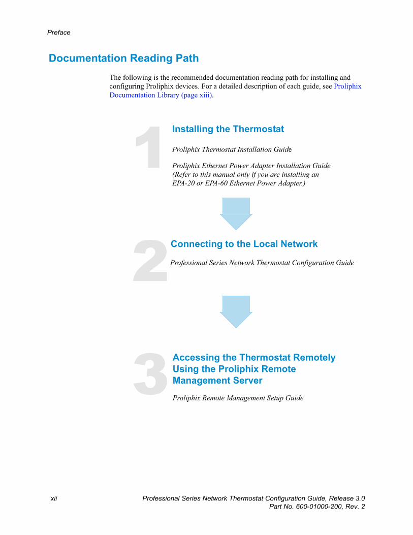
Documentation Reading PathThe following is the recommended documentation reading path for installing and configuring Proliphix devices. For a detailed description of each guide, see Proliphix Documentation Library (page xiii).
1
2
3
Installing the Thermostat
Proliphix Thermostat Installation Guide
Proliphix Ethernet Power Adapter Installation Guide (Refer to this manual only if you are installing an EPA-20 or EPA-60 Ethernet Power Adapter.)
Connecting to the Local Network
Professional Series Network Thermostat Configuration Guide
Accessing the Thermostat RemotelyUsing the Proliphix Remote Management Server
Proliphix Remote Management Setup Guide
Beta Draft ConfidentialPreface
Professional Series Network Thermostat Configuration Guide, Release 3.0 xiiiPart No. 600-01000-200, Rev. 2
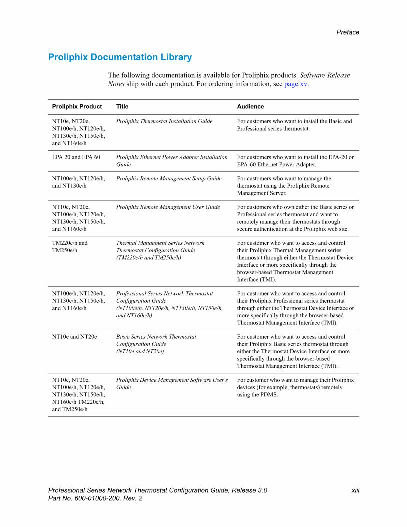
Proliphix Documentation Library
The following documentation is available for Proliphix products. Software Release Notes ship with each product. For ordering information, see page xv.
Proliphix Product Title Audience
NT10e, NT20e, NT100e/h, NT120e/h, NT130e/h, NT150e/h, and NT160e/h
Proliphix Thermostat Installation Guide For customers who want to install the Basic and Professional series thermostat.
EPA 20 and EPA 60 Proliphix Ethernet Power Adapter Installation Guide
For customers who want to install the EPA-20 or EPA-60 Ethernet Power Adapter.
NT100e/h, NT120e/h, and NT130e/h
Proliphix Remote Management Setup Guide For customers who want to manage the thermostat using the Proliphix Remote Management Server.
NT10e, NT20e, NT100e/h, NT120e/h, NT130e/h, NT150e/h, and NT160e/h
Proliphix Remote Management User Guide For customers who own either the Basic series or Professional series thermostat and want to remotely manage their thermostats through secure authentication at the Proliphix web site.
TM220e/h and TM250e/h
Thermal Managment Series Network Thermostat Configuration Guide(TM220e/h and TM250e/h)
For customer who want to access and control their Proliphix Thermal Management series thermostat through either the Thermostat Device Interface or more specifically through the browser-based Thermostat Management Interface (TMI).
NT100e/h, NT120e/h, NT130e/h, NT150e/h, and NT160e/h
Professional Series Network Thermostat Configuration Guide(NT100e/h, NT120e/h, NT130e/h, NT150e/h, and NT160e/h)
For customer who want to access and control their Proliphix Professional series thermostat through either the Thermostat Device Interface or more specifically through the browser-based Thermostat Management Interface (TMI).
NT10e and NT20e Basic Series Network Thermostat Configuration Guide(NT10e and NT20e)
For customer who want to access and control their Proliphix Basic series thermostat through either the Thermostat Device Interface or more specifically through the browser-based Thermostat Management Interface (TMI).
NT10e, NT20e, NT100e/h, NT120e/h, NT130e/h, NT150e/h, NT160e/h TM220e/h, and TM250e/h
Proliphix Device Management Software User’s Guide
For customer who want to manage their Proliphix devices (for example, thermostats) remotely using the PDMS.

Beta Draft Confidential
xiv Professional Series Network Thermostat Configuration Guide, Release 3.0Part No. 600-01000-200, Rev. 2
Preface
ConventionsThis guide uses the following conventions, when applicable:
Description Convention and Example
Commands or keywords, file or path names Boldface font
Variable parameters for which you supply values <courier italics>
Options and arguments for which you supply values [ ]
Information that the user must enter Courier Bold font
Screen messages or system output Courier Regular font
Selecting a menu item Menu => Option
Book titles, new terms, and emphasized text Italics
NoteAdditional information that may apply to the subject text.
Caution
Proceed carefully to avoid possible equipment damage or data loss.
Warning
Proceed carefully to avoid possible personal injury.
TipProvide helpful suggestions.
Beta Draft ConfidentialPreface
Professional Series Network Thermostat Configuration Guide, Release 3.0 xvPart No. 600-01000-200, Rev. 2
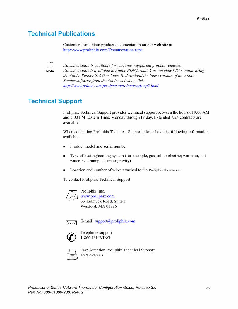
Technical PublicationsCustomers can obtain product documentation on our web site at http://www.proliphix.com/Documenation.aspx.
Technical SupportProliphix Technical Support provides technical support between the hours of 9:00 AM and 5:00 PM Eastern Time, Monday through Friday. Extended 7/24 contracts are available.
When contacting Proliphix Technical Support, please have the following information available:
Product model and serial number
Type of heating/cooling system (for example, gas, oil, or electric; warm air, hot water, heat pump, steam or gravity)
Location and number of wires attached to the Proliphix thermostat
To contact Proliphix Technical Support:
NoteDocumentation is available for currently supported product releases. Documentation is available in Adobe PDF format. You can view PDFs online using the Adobe Reader ® 6.0 or later. To download the latest version of the Adobe Reader software from the Adobe web site, click http://www.adobe.com/products/acrobat/readstep2.html.
Proliphix, Inc. www.proliphix.com66 Tadmuck Road, Suite 1Westford, MA 01886
E-mail: [email protected]
Telephone support1-866-IPLIVING
Fax: Attention Proliphix Technical Support1-978-692-3378
Beta Draft Confidential
xvi Professional Series Network Thermostat Configuration Guide, Release 3.0Part No. 600-01000-200, Rev. 2
Preface
Proliphix Welcomes Your CommentsYou can mail, email, or fax your comments. Please include the document part number in the subject line of your email or fax message.
E-mail: [email protected]
Fax: Attention Technical Publications978-692-3378
Proliphix, Inc. Technical Publications66 Tadmuck Road, Suite 1Westford, MA 01886
Chapter
Professional Series Network Thermostat Configuration Guide, Release 3.0 1-1Part No. 600-01000-200, Rev. 2
Beta Draft Confidential
1
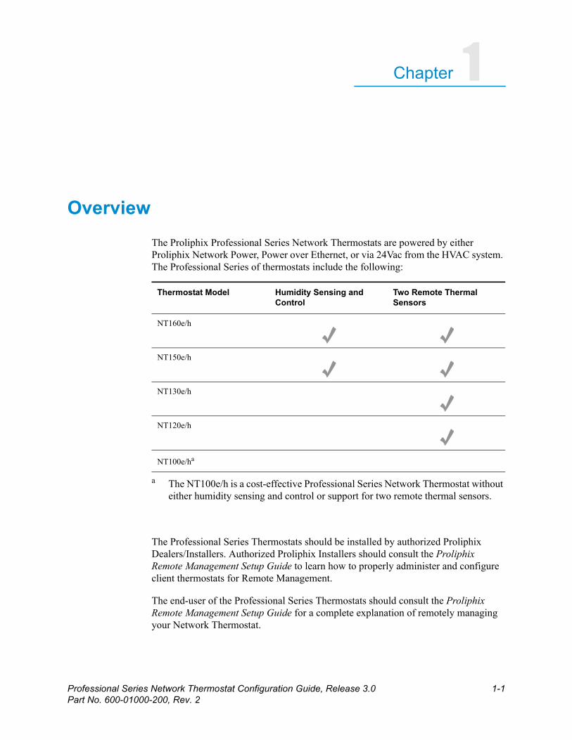
OverviewThe Proliphix Professional Series Network Thermostats are powered by either Proliphix Network Power, Power over Ethernet, or via 24Vac from the HVAC system. The Professional Series of thermostats include the following:
The Professional Series Thermostats should be installed by authorized Proliphix Dealers/Installers. Authorized Proliphix Installers should consult the Proliphix Remote Management Setup Guide to learn how to properly administer and configure client thermostats for Remote Management.
The end-user of the Professional Series Thermostats should consult the Proliphix Remote Management Setup Guide for a complete explanation of remotely managing your Network Thermostat.
Thermostat Model Humidity Sensing and Control
Two Remote Thermal Sensors
NT160e/h
NT150e/h
NT130e/h
NT120e/h
NT100e/ha
a The NT100e/h is a cost-effective Professional Series Network Thermostat without either humidity sensing and control or support for two remote thermal sensors.
Beta Draft Confidential
1-2 Professional Series Network Thermostat Configuration Guide, Release 3.0Part No. 600-01000-200, Rev. 2
CHAPTER 1: Overview
You can configure and manage your thermostat using either the Proliphix Thermostat Management Interface (TMI) or the Thermostat Device Interface (TDI).
Thermostat Management Interface — The Proliphix TMI enables you to manage and control your Proliphix thermostats through your web browser.
Thermostat Device Interface — The buttons on the front of the thermostat enable you to modify the temperature, enable basic HVAC functions, and to view the thermostat’s network configuration and status.
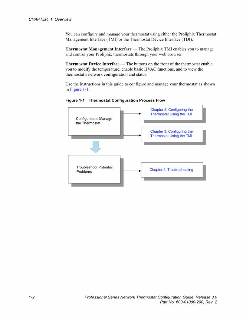
Use the instructions in this guide to configure and manage your thermostat as shown in Figure 1-1.
Figure 1-1 Thermostat Configuration Process Flow
Chapter 2, Configuring the Thermostat Using the TDI
Chapter 3, Configuring the Thermostat Using the TMI
Configure and Manage the Thermostat
Troubleshoot Potential Problems Chapter 4, Troubleshooting
Beta Draft ConfidentialBefore You Begin
Professional Series Network Thermostat Configuration Guide, Release 3.0 1-3Part No. 600-01000-200, Rev. 2
Before You BeginBefore you access and control your Proliphix Network Thermostat through either the TDI or more comprehensively through the browser-based TMI, you must know the IP address and port number of the local thermostat and enable the real time clock. The following sections describe these pre-requisite tasks.
IP Address and Port Number
Your Proliphix Network Thermostat ships from the factory capable to support the DHCP mode for assigning an IP address to your thermostat. See the DHCP Assigned IP Addresses (page 3-2) for more information. You must know the IP address and port number for your thermostat and enter this information in your web browser.
Logging In to the Thermostat
To retrieve the IP address and port number using the Thermostat Device Interface (buttons and control on the front of the thermostat):
1 From the Status & Control Screen (page 2-10), select the Network Status Screen (page 2-15) and record the IP address and port number.
2 Enter this IP address and port number (address:port_number) as the URL in your web browser.
3 Log in to the thermostat as the Administrator as follows:
Username: admin
Password: admin (default)
4 Access the Network Settings Page (page 3-30) in the Thermostat Management Interface.
5 Disable the DHCP function by selecting Static for the IP address method.
6 Enter a unique IP address, Subnet Mask, Gateway, and HTTP port number.
7 Click Submit.
Real Time Clock
Your Proliphix Network Thermostat ships from the factory with the real time clock disabled to ensure longer battery life. You must enable the real time clock to provide years of accurate timekeeping on your thermostat.
To enable the real time clock:
1 On the General Settings Page (page 3-14), check the Set Thermostat Time check box in the Set Date and Time field.
2 Click Submit.
Beta Draft Confidential
1-4 Professional Series Network Thermostat Configuration Guide, Release 3.0Part No. 600-01000-200, Rev. 2
CHAPTER 1: Overview
What’s Next?Continue with Chapter 2, Configuring the Thermostat Using the TDI or Chapter 3, Configuring the Thermostat Using the TMI to manage your thermostat.
Chapter
Professional Series Network Thermostat Configuration Guide, Release 3.0 2-1Part No. 600-01000-200, Rev. 2
Beta Draft Confidential
2
Configuring the Thermostat Using the TDIThis chapter describes how to manually modify certain parameters directly at thethermostat using the Thermostat Device Interface (TDI) (buttons and screen optionson the thermostat). The thermostat’s front panel includes up and down arrows andseveral buttons located at the bottom of the LCD to select the desired configurationsettings.
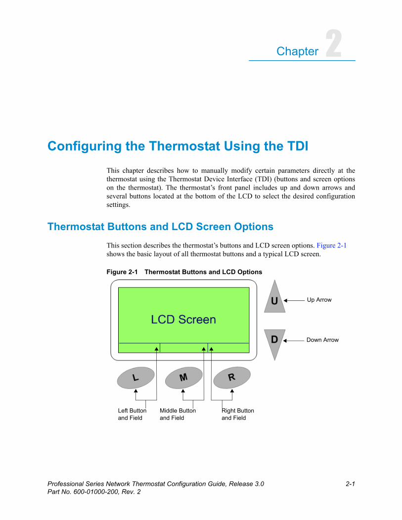
Thermostat Buttons and LCD Screen OptionsThis section describes the thermostat’s buttons and LCD screen options. Figure 2-1 shows the basic layout of all thermostat buttons and a typical LCD screen.
Figure 2-1 Thermostat Buttons and LCD Options
Up Arrow
Down Arrow
Left Buttonand Field
Middle Buttonand Field
Right Buttonand Field

Beta Draft Confidential
2-2 Professional Series Network Thermostat Configuration Guide, Release 3.0Part No. 600-01000-200, Rev. 2
CHAPTER 2: Configuring the Thermostat Using the TDI
Table 2-1 describes the thermostat buttons and LCD options.
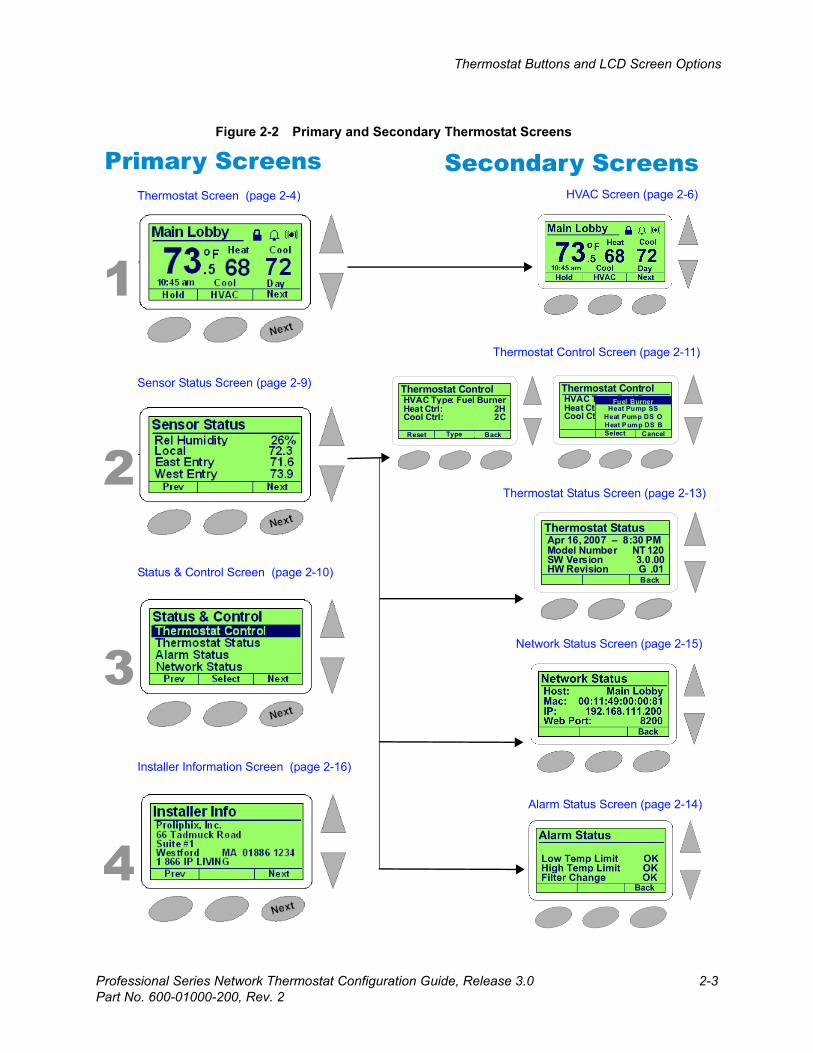
Each thermostat displays content on the LCD screen. The LCD screen is organized into primary and secondary (or sub) screens. Most of the Professional Series thermostats have four primary screens. However, the NT100e/h has three primary screens. This section describes the primary and secondary screens shown in Figure 2-2 on page 2-3.
Table 2-1 Thermostat Buttons and LCD Options
Button or LCD Option Description
Up arrow (multiple uses, screen sensitive)
Increases the setpoint temperature settings. Scrolls up one field in multi-field screens.
Down arrow (multiple uses, screen sensitive)
Decreases the setpoint temperature settings. Scrolls down one field in multi-field screens.
Left button (multiple uses, screen sensitive)
Selects the function displayed on the LCD.
Middle button (multiple uses, screen sensitive)
Selects the function displayed on the LCD.
Right button (multiple uses, screen sensitive)
Selects the function displayed on the LCD.
Left button field Displays the function to be controlled by the left button. In many screens, this field is labeled Prev and enables you to access the previous screen.
Middle button field Displays the function to be controlled by the middle button. In many secondary screens, this field is labeled Select and enables you to select the highlighted field on the screen.
Right button field Displays the function to be controlled by the right button. In many screens, this field is labeled Next and enables you to access the next screen.
Beta Draft ConfidentialThermostat Buttons and LCD Screen Options
Professional Series Network Thermostat Configuration Guide, Release 3.0 2-3Part No. 600-01000-200, Rev. 2
Figure 2-2 Primary and Secondary Thermostat Screens
Thermostat Screen (page 2-4)
Sensor Status Screen (page 2-9)
Status & Control Screen (page 2-10)
Installer Information Screen (page 2-16)
HVAC Screen (page 2-6)
Thermostat Control Screen (page 2-11)
Thermostat Status Screen (page 2-13)
Alarm Status Screen (page 2-14)
Network Status Screen (page 2-15)
Primary Screens Secondary Screens
1
2
3
4
Thermostat Control
Type Back
HVAC Type: Fuel BurnerHeat Ctrl: 2HCool Ctrl: 2C
Reset
Thermostat Status
Back
CoolApr 16, 2007 – 8:30 PMModel Number NT 120SW Version 3.0.00HW Revision G .01
Thermostat Control
Select Cancel
HVAC Type: Fuel BurnerHeat Ctrl: 2HCool Ctrl: 2C
Fuel BurnerHeat Pump SS
Heat Pump DS OHeat Pump DS B
Beta Draft Confidential
2-4 Professional Series Network Thermostat Configuration Guide, Release 3.0Part No. 600-01000-200, Rev. 2
CHAPTER 2: Configuring the Thermostat Using the TDI
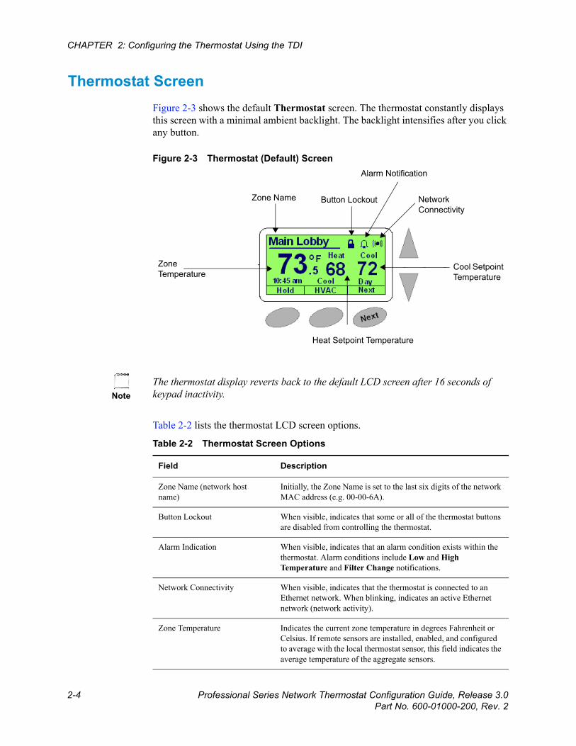
Thermostat Screen Figure 2-3 shows the default Thermostat screen. The thermostat constantly displays this screen with a minimal ambient backlight. The backlight intensifies after you click any button.
Figure 2-3 Thermostat (Default) Screen
Table 2-2 lists the thermostat LCD screen options.
Zone Name Button Lockout
Alarm Notification
Network Connectivity
Cool Setpoint Temperature
Heat Setpoint Temperature
Zone Temperature
NoteThe thermostat display reverts back to the default LCD screen after 16 seconds of keypad inactivity.
Table 2-2 Thermostat Screen Options
Field Description
Zone Name (network host name)
Initially, the Zone Name is set to the last six digits of the network MAC address (e.g. 00-00-6A).
Button Lockout When visible, indicates that some or all of the thermostat buttons are disabled from controlling the thermostat.
Alarm Indication When visible, indicates that an alarm condition exists within the thermostat. Alarm conditions include Low and High Temperature and Filter Change notifications.
Network Connectivity When visible, indicates that the thermostat is connected to an Ethernet network. When blinking, indicates an active Ethernet network (network activity).
Zone Temperature Indicates the current zone temperature in degrees Fahrenheit or Celsius. If remote sensors are installed, enabled, and configured to average with the local thermostat sensor, this field indicates the average temperature of the aggregate sensors.
Beta Draft ConfidentialThermostat Screen
Professional Series Network Thermostat Configuration Guide, Release 3.0 2-5Part No. 600-01000-200, Rev. 2
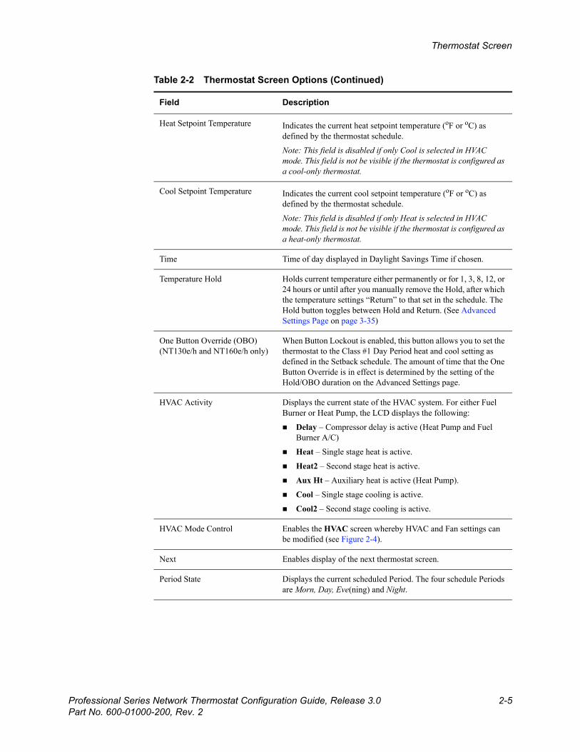
Heat Setpoint Temperature Indicates the current heat setpoint temperature (oF or oC) as defined by the thermostat schedule.
Note: This field is disabled if only Cool is selected in HVAC mode. This field is not be visible if the thermostat is configured as a cool-only thermostat.
Cool Setpoint Temperature Indicates the current cool setpoint temperature (oF or oC) as defined by the thermostat schedule.
Note: This field is disabled if only Heat is selected in HVAC mode. This field is not be visible if the thermostat is configured as a heat-only thermostat.
Time Time of day displayed in Daylight Savings Time if chosen.
Temperature Hold Holds current temperature either permanently or for 1, 3, 8, 12, or 24 hours or until after you manually remove the Hold, after which the temperature settings “Return” to that set in the schedule. The Hold button toggles between Hold and Return. (See Advanced Settings Page on page 3-35)
One Button Override (OBO)(NT130e/h and NT160e/h only)
When Button Lockout is enabled, this button allows you to set the thermostat to the Class #1 Day Period heat and cool setting as defined in the Setback schedule. The amount of time that the One Button Override is in effect is determined by the setting of the Hold/OBO duration on the Advanced Settings page.
HVAC Activity Displays the current state of the HVAC system. For either Fuel Burner or Heat Pump, the LCD displays the following:
Delay – Compressor delay is active (Heat Pump and Fuel Burner A/C)
Heat – Single stage heat is active.
Heat2 – Second stage heat is active.
Aux Ht – Auxiliary heat is active (Heat Pump).
Cool – Single stage cooling is active.
Cool2 – Second stage cooling is active.
HVAC Mode Control Enables the HVAC screen whereby HVAC and Fan settings can be modified (see Figure 2-4).
Next Enables display of the next thermostat screen.
Period State Displays the current scheduled Period. The four schedule Periods are Morn, Day, Eve(ning) and Night.
Table 2-2 Thermostat Screen Options (Continued)
Field Description
Beta Draft Confidential
2-6 Professional Series Network Thermostat Configuration Guide, Release 3.0Part No. 600-01000-200, Rev. 2
CHAPTER 2: Configuring the Thermostat Using the TDI
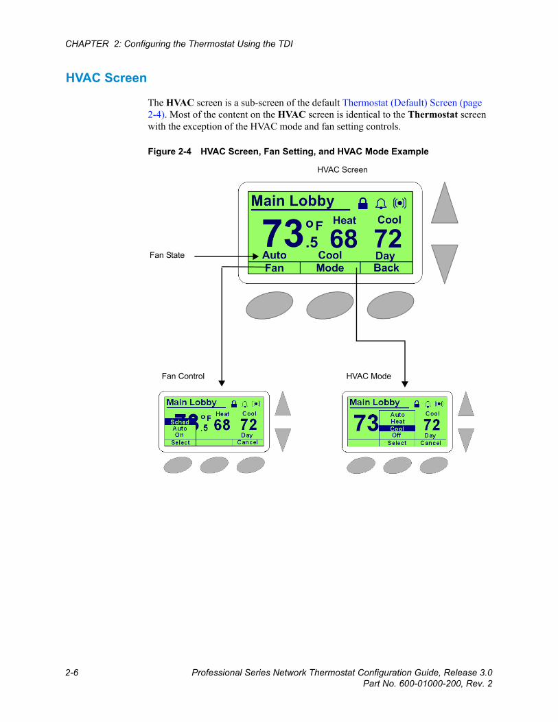
HVAC Screen
The HVAC screen is a sub-screen of the default Thermostat (Default) Screen (page 2-4). Most of the content on the HVAC screen is identical to the Thermostat screen with the exception of the HVAC mode and fan setting controls.
Figure 2-4 HVAC Screen, Fan Setting, and HVAC Mode Example
Fan Control
Fan State
HVAC Mode
HVAC Screen
Beta Draft ConfidentialThermostat Screen
Professional Series Network Thermostat Configuration Guide, Release 3.0 2-7Part No. 600-01000-200, Rev. 2
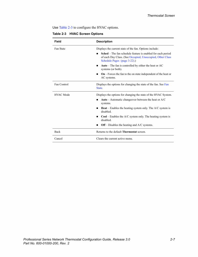
Use Table 2-3 to configure the HVAC options.
Table 2-3 HVAC Screen Options
Field Description
Fan State Displays the current state of the fan. Options include:
Sched – The fan schedule feature is enabled for each period of each Day Class. (See Occupied, Unoccupied, Other Class Schedule Pages (page 3-22).)
Auto – The fan is controlled by either the heat or AC systems (or both).
On – Forces the fan to the on state independent of the heat or AC systems.
Fan Control Displays the options for changing the state of the fan. See Fan State.
HVAC Mode Displays the options for changing the state of the HVAC System.
Auto – Automatic changeover between the heat or A/C systems.
Heat – Enables the heating system only. The A/C system is disabled.
Cool – Enables the A/C system only. The heating system is disabled.
Off – Disables the heating and A/C systems.
Back Returns to the default Thermostat screen.
Cancel Clears the current active menu.
Beta Draft Confidential
2-8 Professional Series Network Thermostat Configuration Guide, Release 3.0Part No. 600-01000-200, Rev. 2
CHAPTER 2: Configuring the Thermostat Using the TDI
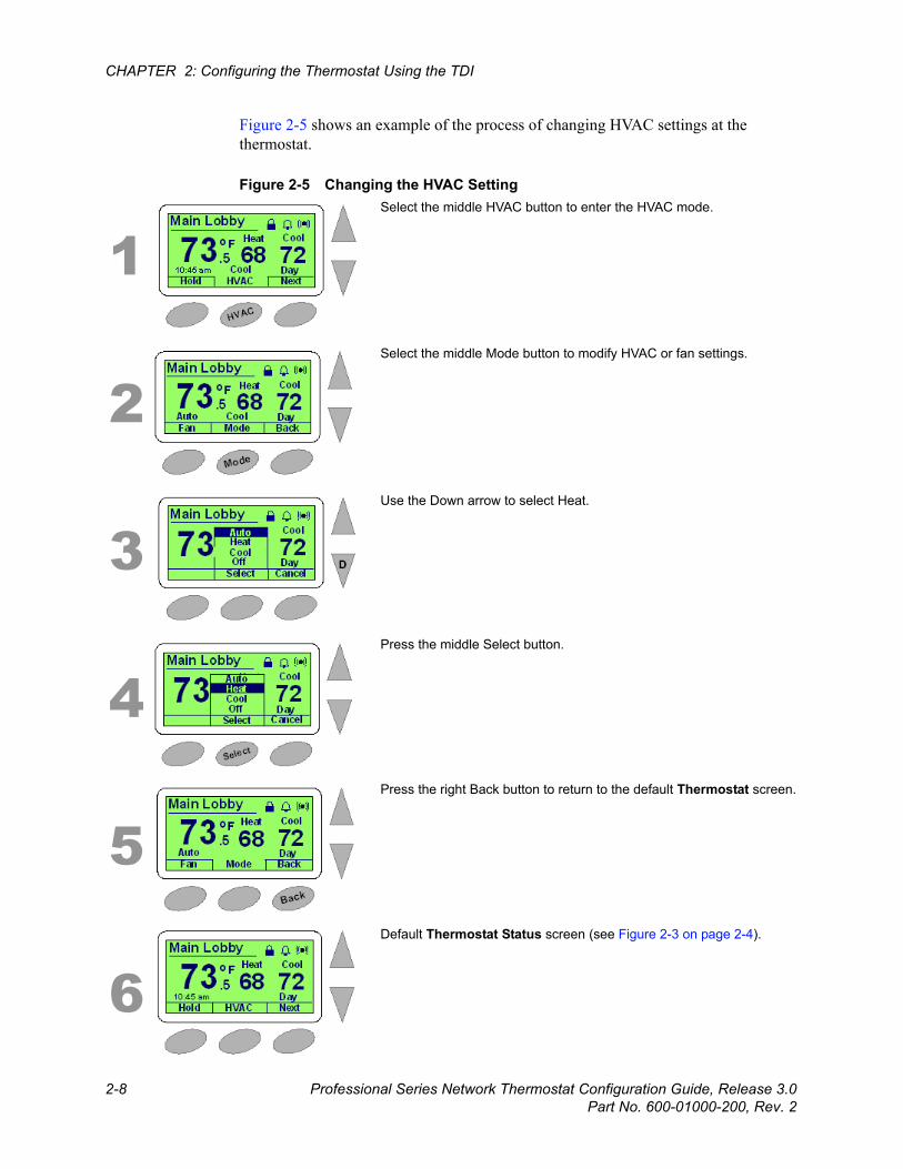
Figure 2-5 shows an example of the process of changing HVAC settings at the thermostat.
Figure 2-5 Changing the HVAC Setting
1
2
3
4
5
6
Select the middle HVAC button to enter the HVAC mode.
Select the middle Mode button to modify HVAC or fan settings.
Use the Down arrow to select Heat.
Press the middle Select button.
Press the right Back button to return to the default Thermostat screen.
Default Thermostat Status screen (see Figure 2-3 on page 2-4).
Beta Draft ConfidentialThermostat Screen
Professional Series Network Thermostat Configuration Guide, Release 3.0 2-9Part No. 600-01000-200, Rev. 2
Sensor Status Screen
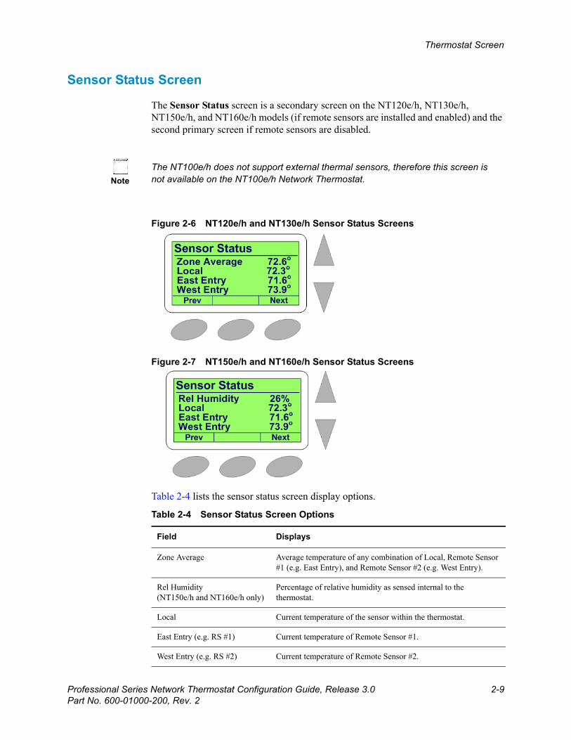
The Sensor Status screen is a secondary screen on the NT120e/h, NT130e/h, NT150e/h, and NT160e/h models (if remote sensors are installed and enabled) and the second primary screen if remote sensors are disabled.
Figure 2-6 NT120e/h and NT130e/h Sensor Status Screens
Figure 2-7 NT150e/h and NT160e/h Sensor Status Screens
Table 2-4 lists the sensor status screen display options.
NoteThe NT100e/h does not support external thermal sensors, therefore this screen is not available on the NT100e/h Network Thermostat.
Table 2-4 Sensor Status Screen Options
Field Displays
Zone Average Average temperature of any combination of Local, Remote Sensor #1 (e.g. East Entry), and Remote Sensor #2 (e.g. West Entry).
Rel Humidity(NT150e/h and NT160e/h only)
Percentage of relative humidity as sensed internal to the thermostat.
Local Current temperature of the sensor within the thermostat.
East Entry (e.g. RS #1) Current temperature of Remote Sensor #1.
West Entry (e.g. RS #2) Current temperature of Remote Sensor #2.
Beta Draft Confidential
2-10 Professional Series Network Thermostat Configuration Guide, Release 3.0Part No. 600-01000-200, Rev. 2
CHAPTER 2: Configuring the Thermostat Using the TDI
Status & Control Screen
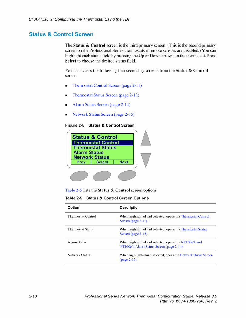
The Status & Control screen is the third primary screen. (This is the second primary screen on the Professional Series thermostats if remote sensors are disabled.) You can highlight each status field by pressing the Up or Down arrows on the thermostat. Press Select to choose the desired status field.
You can access the following four secondary screens from the Status & Control screen:
Thermostat Control Screen (page 2-11)
Thermostat Status Screen (page 2-13)
Alarm Status Screen (page 2-14)
Network Status Screen (page 2-15)
Figure 2-8 Status & Control Screen
Table 2-5 lists the Status & Control screen options.
Table 2-5 Status & Control Screen Options
Option Description
Thermostat Control When highlighted and selected, opens the Thermostat Control Screen (page 2-11).
Thermostat Status When highlighted and selected, opens the Thermostat Status Screen (page 2-13).
Alarm Status When highlighted and selected, opens the NT150e/h and NT160e/h Alarm Status Screen (page 2-14).
Network Status When highlighted and selected, opens the Network Status Screen (page 2-15).

Beta Draft ConfidentialThermostat Screen
Professional Series Network Thermostat Configuration Guide, Release 3.0 2-11Part No. 600-01000-200, Rev. 2
Thermostat Control Screen
The Thermostat Control screen is a sub-screen of the Status & Control Screen (page 2-10). You can select the HVAC system type on this screen. This screen also displays the status of the selected type along with the default settings.
To change specific parameters for each type, go to the Advanced Settings Page (page 3-35). To initiate a software reset, press the left button and see Resetting the Thermostat (page 4-1).
Figure 2-9 Thermostat Control Screen
Thermostat Control
Type Back
HVAC Type: Fuel BurnerHeat Ctrl: 2HCool Ctrl: 2C
Reset
Thermostat Control
Select Cancel
HVAC Type: Fuel BurnerHeat Ctrl: 2HCool Ctrl: 2C
Fuel BurnerHeat Pump SS
Heat Pump DS OHeat Pump DS B

Beta Draft Confidential
2-12 Professional Series Network Thermostat Configuration Guide, Release 3.0Part No. 600-01000-200, Rev. 2
CHAPTER 2: Configuring the Thermostat Using the TDI
Use Table 2-6 to configure the Thermostat Status screen options.
Table 2-6 Thermostat Status Screen Options
Field Description
Reset Press and hold the Reset button for three (3) seconds to perform a software reboot.
Type Select either Fuel Burner (default) or Heat Pump. When selecting between either Fuel Burner or Heat Pump or between Heat Pump and Fuel Burner, the HVAC Mode must be set to OFF prior to selecting the opposite setting. (See Changing the HVAC Setting (page 2-8) or Status & Control Page (page 3-9).
Fuel Burner – Fossil fuel systems which includes oil or gas-fired boilers or furnaces.
Heat Pump SS – Electric heat pump (Single Stage) HVAC system type.
Heat Pump DS O – Electric heat pump (Dual Stage O Rvs. Valve) HVAC system type.
Heat Pump DS B – Electric heat pump (Dual Stage B Rvs. Valve) HVAC system type.
See the Advanced Settings Page (page 3-35) further explanation of the following parameters.
HVAC Type Displays the selected HVAC system type; Fuel Burner or Heat Pump.
Fuel Burner:
Heat Ctrl:
Disable – No heating system is present.
2H – Dual Stage heating is enabled.
1H – Single Stage heating is enabled.
Cool Ctrl:
Disable – No cooling system is present.
2C – Dual Stage cooling is enabled.
1C – Single Stage cooling is enabled.
Heat Pump:
Heat Ctrl:
Disable – No heating system is present (i.e. air conditioning only)
2H – Dual Stage heating is enabled.
1H – Single Stage heating is enabled.
Aux Heat – Auxiliary heat is enabled to augment the heat pump.
Cool Ctrl:
Disable – No cooling system is present (i.e. heat only)
2C – Dual Stage cooling is enabled.
1C – Single Stage cooling is enabled.
Beta Draft ConfidentialThermostat Screen
Professional Series Network Thermostat Configuration Guide, Release 3.0 2-13Part No. 600-01000-200, Rev. 2
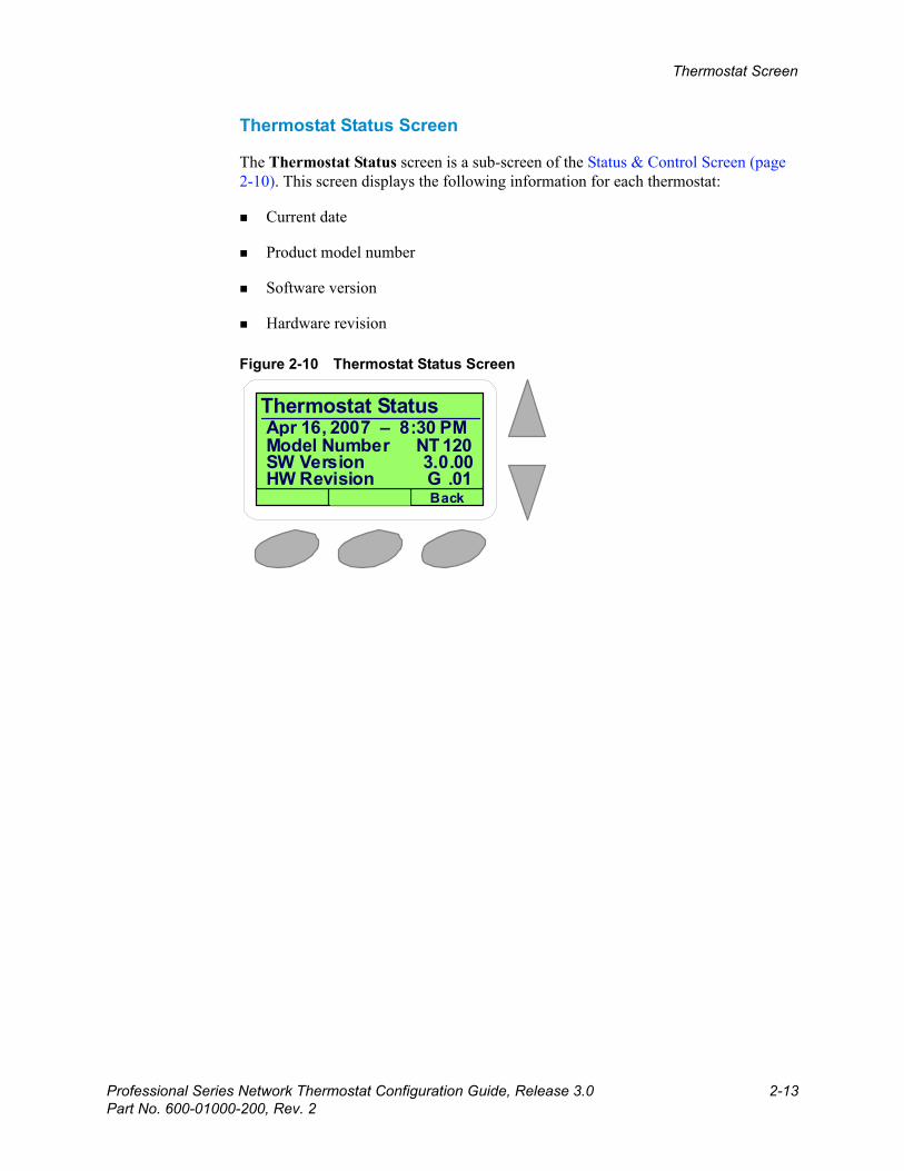
Thermostat Status Screen
The Thermostat Status screen is a sub-screen of the Status & Control Screen (page 2-10). This screen displays the following information for each thermostat:
Current date
Product model number
Software version
Hardware revision
Figure 2-10 Thermostat Status Screen
Thermostat Status
Back
CoolApr 16, 2007 – 8:30 PMModel Number NT 120SW Version 3.0.00HW Revision G .01
Beta Draft Confidential
2-14 Professional Series Network Thermostat Configuration Guide, Release 3.0Part No. 600-01000-200, Rev. 2
CHAPTER 2: Configuring the Thermostat Using the TDI
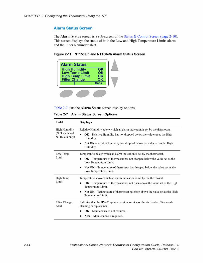
Alarm Status Screen
The Alarm Status screen is a sub-screen of the Status & Control Screen (page 2-10). This screen displays the status of both the Low and High Temperature Limits alarm and the Filter Reminder alert.
Figure 2-11 NT150e/h and NT160e/h Alarm Status Screen
Table 2-7 lists the Alarm Status screen display options.
Table 2-7 Alarm Status Screen Options
Field Displays
High Humidity(NT150e/h and NT160e/h only)
Relative Humidity above which an alarm indication is set by the thermostat.
OK – Relative Humidity has not dropped below the value set as the High Humidity.
Not OK – Relative Humidity has dropped below the value set as the High Humidity.
Low Temp Limit
Temperature below which an alarm indication is set by the thermostat.
OK – Temperature of thermostat has not dropped below the value set as the Low Temperature Limit.
Not OK – Temperature of thermostat has dropped below the value set as the Low Temperature Limit.
High Temp Limit
Temperature above which an alarm indication is set by the thermostat.
OK – Temperature of thermostat has not risen above the value set as the High Temperature Limit.
Not OK – Temperature of thermostat has risen above the value set as the High Temperature Limit.
Filter Change Alert
Indicates that the HVAC system requires service or the air handler filter needs cleaning or replacement.
OK – Maintenance is not required.
Now – Maintenance is required.
Beta Draft ConfidentialThermostat Screen
Professional Series Network Thermostat Configuration Guide, Release 3.0 2-15Part No. 600-01000-200, Rev. 2
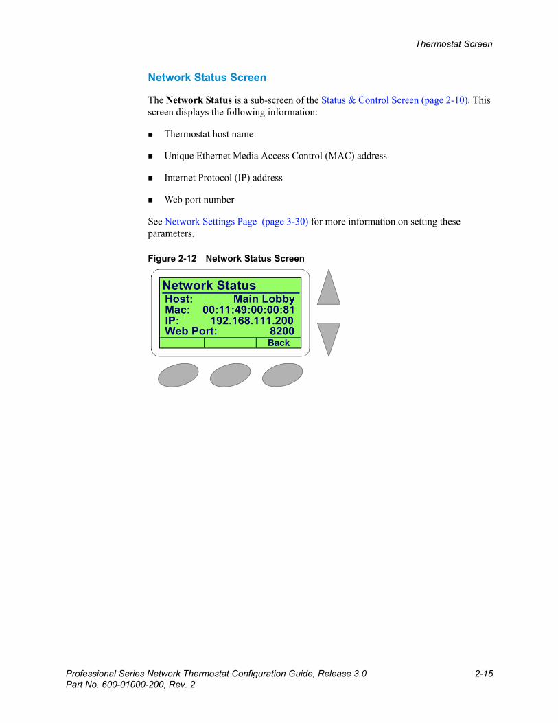
Network Status Screen
The Network Status is a sub-screen of the Status & Control Screen (page 2-10). This screen displays the following information:
Thermostat host name
Unique Ethernet Media Access Control (MAC) address
Internet Protocol (IP) address
Web port number
See Network Settings Page (page 3-30) for more information on setting these parameters.
Figure 2-12 Network Status Screen
Beta Draft Confidential
2-16 Professional Series Network Thermostat Configuration Guide, Release 3.0Part No. 600-01000-200, Rev. 2
CHAPTER 2: Configuring the Thermostat Using the TDI
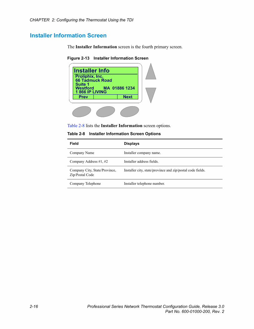
Installer Information Screen
The Installer Information screen is the fourth primary screen.
Figure 2-13 Installer Information Screen
Table 2-8 lists the Installer Information screen options.
Table 2-8 Installer Information Screen Options
Field Displays
Company Name Installer company name.
Company Address #1, #2 Installer address fields.
Company City, State/Province, Zip/Postal Code
Installer city, state/province and zip/postal code fields.
Company Telephone Installer telephone number.
Chapter
Professional Series Network Thermostat Configuration Guide, Release 3.0 3-1Part No. 600-01000-200, Rev. 2
Beta Draft Confidential
3
Configuring the Thermostat Using the TMIThis chapter describes how to connect the thermostat to your local network and configure and monitor the thermostat through the web browser using the Thermostat Management Interface (TMI).
Thermostat Management Interface (TMI) AuthenticationThe TMI for all Professional Series thermostats requires password authentication prior to accessing the HTML pages that enable you to control or manage the thermostats. There are two levels of authentication allowed to manage the Professional Series thermostats; the Administrator account has the highest level of privileges and the User account has the lowest level of account privileges. The username and password for each account is as follows:
Administrator Account
Username: admin
Password: admin (default)
User Account
Username: user
Password: admin (default)
TipYou can change each of these passwords within each account after the initial authentication. For more information, see Password Settings Page (page 3-56).
Beta Draft Confidential
3-2 Professional Series Network Thermostat Configuration Guide, Release 3.0Part No. 600-01000-200, Rev. 2
CHAPTER 3: Configuring the Thermostat Using the TMI
DHCP Assigned IP Addresses
The Professional Series thermostats ship directly from the factory enabled to perform as a Dynamic Host Configuration Protocol (DHCP) client. DHCP is an established standard used to assign IP addresses automatically after each network device is inserted into the network or when the device experiences a power cycle. DHCP allows devices on your local network to receive their Internet Protocol (IP) addresses automatically from an attached DHCP server typically located within a local router. Devices located on the same network as the router may include DHCP client software. This software works in conjunction with the router’s DHCP Server to request and receive both an IP address and Gateway Address.
If your file server or router supports DHCP, then your Proliphix thermostat automatically retrieves an IP Address, Gateway Address, and Subnet Mask from the DHCP server on your network.
Before you BeginBefore you access the TMI to control and manage your thermostat, complete the following prerequisite tasks described in this section:
Connect the thermostat to the network.
Obtain the device name, default host name, IP address, and Web Port identifier.
Establish the thermostat’s identity for remote management.
NoteProliphix strongly recommends that a DHCP server be installed and operational in your network prior to installing the thermostat.If a DHCP server is unavailable on your network, your thermostat will default to the 169.254.111.111 IP address within 60 seconds once you press the “abort” key on the Network Status screen on the TDI. Note that this address is not unique to your network if more than one thermostat is installed on a network without a DHCP server. That is, there will be multiple thermostats on the network with the same IP address (i.e. 169.254.111.111). Addressing conflicts will exist and most of the thermostats will be inaccessible.
Beta Draft ConfidentialBefore you Begin
Professional Series Network Thermostat Configuration Guide, Release 3.0 3-3Part No. 600-01000-200, Rev. 2
Connecting the Thermostat to the Local Network
This section describes how to connect your Professional Series thermostat to your local data network. This connection enables you to conveniently and efficiently configure your thermostat using a browser on your laptop or desktop personal computer. If a broadband connection is available on your local network, you can also remotely manage and configure your thermostat via the Internet.
To connect the thermostat to your local network:
1 Using a standard patch cable, complete the connection of your thermostat(s) to the local switch or router. Your thermostat(s) should automatically communicate with the local DHCP server and be assigned a unique IP address.
2 Go to the physical location of each thermostat and record the following information using the worksheet below. Use a separate piece of paper if necessary.
Information Thermostat 1 Thermostat 2 Thermostat 3
Device Name (Zone Name) of the thermostat
Located in the upper-left corner of the Thermostat (Default) Screen (page 2-4).
Default host name of the thermostat
The last six digits of the Proliphix-assigned device MAC address in the format “AB:CD:EF”. See Network Status Screen (page 2-15).
IP Address and Web Port identifier
Select the Network Status Screen (page 2-15) under the Status & Control Screen (page 2-10).
TipYou will refer to this information later in this guide when you configure your thermostat(s) for Remote Management. Keep this information as a reference in case you need to change your thermostat(s) network settings.
Beta Draft Confidential
3-4 Professional Series Network Thermostat Configuration Guide, Release 3.0Part No. 600-01000-200, Rev. 2
CHAPTER 3: Configuring the Thermostat Using the TMI
Remote Management
You can manage the Professional Series thermostat using a web browser on a local area network (LAN) or remotely though the Internet after proper authentication at the Proliphix Web Site (www.proliphix.com).
Logging In to the Thermostat
To establish the identity of the thermostat for Remote Management capability: (See the Proliphix Installer Remote Management Guide and the Proliphix Remote Management User Guide for detailed information.)
1 Log in to the TMI as the Administrator as follows:
Username: admin
Password: admin (default)
2 Access the General Settings Page (page 3-14) through the TMI.
3 Enter a Device Name and Site Name (for example, the name or location of the property).
4 Click Submit.
5 Access the Network Settings Page (page 3-30).
6 Set the IP Address Method to Static and select a unique IP address, Subnet Mask, Gateway, and HTTP port number.
7 Click Submit.
8 Access the Remote Access Page (page 3-49).
9 Click Submit.
NoteIf you use a VPN to access your thermostats remotely, the thermostats appear to reside on the “local” network. In this case, you do not need to control the thermostats through the Proliphix Remote Management Service via the Proliphix Web Site. If the Proliphix Remote Management Service is not used however, email notification due to alarm conditions is not available.
Beta Draft ConfidentialThermostat Management Interface (TMI)
Professional Series Network Thermostat Configuration Guide, Release 3.0 3-5Part No. 600-01000-200, Rev. 2
Thermostat Management Interface (TMI)The Proliphix Thermostat Management Interface (TMI) provides network management capability to control your Professional Series thermostats. This section describes the browser-based configuration using the TMI. Review the instructions in this section prior to configuring your thermostat.
HTML Interface
To access the initial HTML page of the thermostat, enter the unique IP address initially assigned via DHCP (see page 3-2) and the Web HTTP port number in your browser window. For example:
http://192.168.111.100:80Where 192.168.111.100 is a unique IP address initially assigned via DHCP and 80 is the default (Proliphix assigned) Web HTTP port number. (If you are upgrading your device from a previous version of Proliphix firmware, this port number may be something other than 80. The old port number is carried forward after the firmware upgrade.) After you enter these two fields into the browser, the system displays the first TMI page.
TipProliphix recommends that these parameters be fixed “statically” so that this address can be bookmarked in your browser. Proliphix recommends that you choose a unique static IP address assigned from outside the DHCP server pool of addresses. See the Network Settings Page (page 3-30) for more information on static IP address assignment.
Beta Draft Confidential
3-6 Professional Series Network Thermostat Configuration Guide, Release 3.0Part No. 600-01000-200, Rev. 2
CHAPTER 3: Configuring the Thermostat Using the TMI
Most of the HTML thermostat pages conform to a standard format which is maintained for both local and remote thermostat access. (See Figure on page 3-7.) A yellow banner at the top of each page contains the following information for each thermostat:
Model number
Page title
Host name of the thermostat
Each thermostat page also includes browser buttons which enable direct access to all other HTML pages on the thermostat. The TMI displays each page in a table format. Each feature table is organized by rows of functions, in a left to right direction as follows:
Field name
Function status (in light blue)
Function control (text boxes and drop-down selections)

Beta Draft ConfidentialLogging In to the Thermostat
Professional Series Network Thermostat Configuration Guide, Release 3.0 3-7Part No. 600-01000-200, Rev. 2
Logging In to the ThermostatWhen you access the thermostat for the first time, the default Status & Control (Login) page appears. Proliphix recommends that either the thermostat administrator (admin) or a user (user) log in to the thermostat from this page. The thermostat’s status is visible to either account without logging in, but you must log in to control some of the parameters on this page.
Figure 3-1 Status & Control (Login) Page
NoteIn each TMI page, you must click Submit to apply all changes made in the Control column. Click Refresh to update the status.
Click Login

Beta Draft Confidential
3-8 Professional Series Network Thermostat Configuration Guide, Release 3.0Part No. 600-01000-200, Rev. 2
CHAPTER 3: Configuring the Thermostat Using the TMI
To log in and access TMI pages:
1 Click Login.
The login window appears. (See Figure 3-2.) Proper authentication is required before you can access any other thermostat TMI pages.
Figure 3-2 Administrator (or User) Authentication Window
2 Enter the default username and password for the admin or user account as follows: and click OK.
3 Continue with the Status & Control Page.
Field Admin Account User Account
Username admin user
Passworda
a You can change passwords for each account using the Password Settings Page (page 3-56).
admin admin
NoteThe Administrator can access all installer-specific pages.
The User account is limited to viewing and controlling the following pages:Status & Control Page (page 3-9), General Settings Page (page 3-14), Setback Schedules Page (page 3-19) and Password Settings Page (page 3-56).
Beta Draft ConfidentialStatus & Control Page
Professional Series Network Thermostat Configuration Guide, Release 3.0 3-9Part No. 600-01000-200, Rev. 2
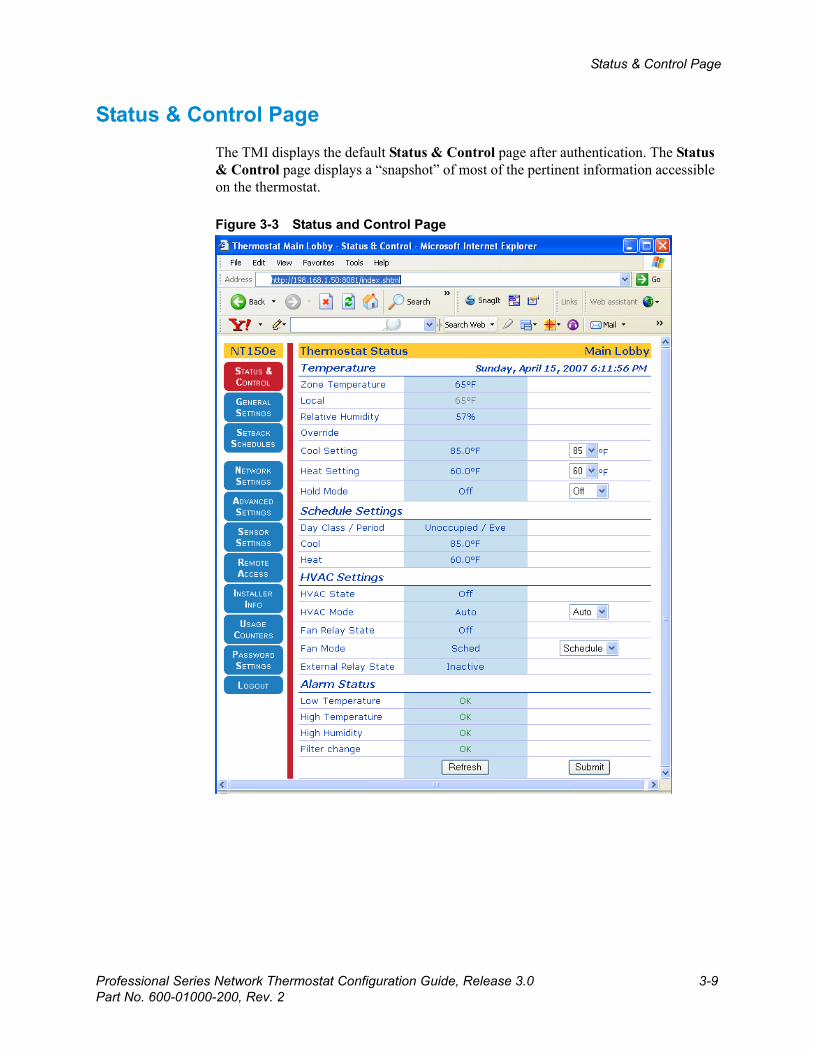
Status & Control PageThe TMI displays the default Status & Control page after authentication. The Status & Control page displays a “snapshot” of most of the pertinent information accessible on the thermostat.
Figure 3-3 Status and Control Page
Beta Draft Confidential
3-10 Professional Series Network Thermostat Configuration Guide, Release 3.0Part No. 600-01000-200, Rev. 2
CHAPTER 3: Configuring the Thermostat Using the TMI
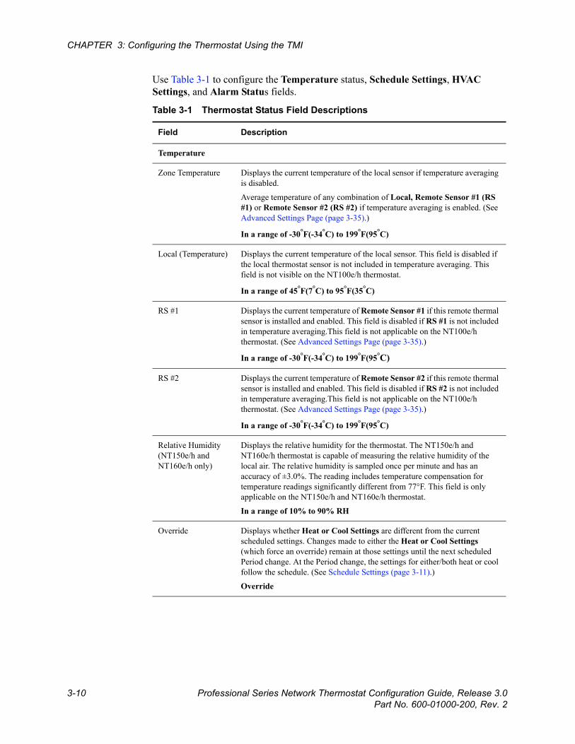
Use Table 3-1 to configure the Temperature status, Schedule Settings, HVAC Settings, and Alarm Status fields.
Table 3-1 Thermostat Status Field Descriptions
Field Description
Temperature
Zone Temperature Displays the current temperature of the local sensor if temperature averaging is disabled.
Average temperature of any combination of Local, Remote Sensor #1 (RS #1) or Remote Sensor #2 (RS #2) if temperature averaging is enabled. (See Advanced Settings Page (page 3-35).)
In a range of -30°F(-34°C) to 199°F(95°C)
Local (Temperature) Displays the current temperature of the local sensor. This field is disabled if the local thermostat sensor is not included in temperature averaging. This field is not visible on the NT100e/h thermostat.
In a range of 45°F(7°C) to 95°F(35°C)
RS #1 Displays the current temperature of Remote Sensor #1 if this remote thermal sensor is installed and enabled. This field is disabled if RS #1 is not included in temperature averaging.This field is not applicable on the NT100e/h thermostat. (See Advanced Settings Page (page 3-35).)
In a range of -30°F(-34°C) to 199°F(95°C)
RS #2 Displays the current temperature of Remote Sensor #2 if this remote thermal sensor is installed and enabled. This field is disabled if RS #2 is not included in temperature averaging.This field is not applicable on the NT100e/h thermostat. (See Advanced Settings Page (page 3-35).)
In a range of -30°F(-34°C) to 199°F(95°C)
Relative Humidity (NT150e/h and NT160e/h only)
Displays the relative humidity for the thermostat. The NT150e/h and NT160e/h thermostat is capable of measuring the relative humidity of the local air. The relative humidity is sampled once per minute and has an accuracy of ±3.0%. The reading includes temperature compensation for temperature readings significantly different from 77°F. This field is only applicable on the NT150e/h and NT160e/h thermostat.
In a range of 10% to 90% RH
Override Displays whether Heat or Cool Settings are different from the current scheduled settings. Changes made to either the Heat or Cool Settings (which force an override) remain at those settings until the next scheduled Period change. At the Period change, the settings for either/both heat or cool follow the schedule. (See Schedule Settings (page 3-11).)
Override

Beta Draft ConfidentialStatus & Control Page
Professional Series Network Thermostat Configuration Guide, Release 3.0 3-11Part No. 600-01000-200, Rev. 2
Cool Setting Displays the current temperature programmed for the cooling (A/C) system. This field is disabled if the HVAC mode is set to Heat or Off. (See HVAC Mode (page 3-12).) This field is not visible if the thermostat is configured to be a heat-only controlling device. (See Advanced Settings Page (page 3-35).)
To modify this field, use the drop-down menu to select a Cool Setting.
40°F(4.5°C) to 99°F(37°C)
Heat Setting Displays the current temperature programmed for the heating system. This field is disabled if the HVAC mode is set to Cool or Off. (See HVAC Mode (page 3-12).) This field is not visible if the thermostat is configured to be a cool-only controlling device. (See Advanced Settings Page (page 3-35).)
To modify this field, use the drop-down menu to select a Heat Setting.
40°F(4.5°C) to 99°F(37°C)
Hold Mode Displays the current state for both the Heat and Cool Setting. To “hold” the current settings indefinitely or for a prescribed period of time as set on the Advanced Settings Page (page 3-35), use the drop-down menu and choose
Hold – Hold mode is enabled.
Off (default) – Hold mode is disabled.
Schedule Settings
Day Class / Period Displays the current settings for both the scheduled Day Class and Period. (See Setback Schedules Page (page 3-19).)
Cool Displays the current Cool temperature setting as set within the current Day Class schedule. (See Setback Schedules Page (page 3-19).)
40°F(4.5°C) to 99°F(37°C)
Heat Displays the current Heat temperature setting as set within the current Day Class schedule. (See Setback Schedules Page (page 3-19).)
40°F(4.5°C) to 99°F(37°C)
HVAC Settings
HVAC State Displays the current state of the heating or cooling system. If a state change is made while viewing this page, click Refresh to update the status.
Heat – First stage heat is actively heating.
Heat2 – First stage and second stage heat are actively heating. (Fuel Burner)
Aux Ht – First stage and auxiliary heat are actively heating. (Heat Pump)
Cool – First stage cool is actively cooling.
Cool2 – First stage and second stage A/C are actively cooling.
Off – Neither the heating system or cooling system is active (i.e. on).
Table 3-1 Thermostat Status Field Descriptions (Continued)
Field Description
Beta Draft Confidential
3-12 Professional Series Network Thermostat Configuration Guide, Release 3.0Part No. 600-01000-200, Rev. 2
CHAPTER 3: Configuring the Thermostat Using the TMI
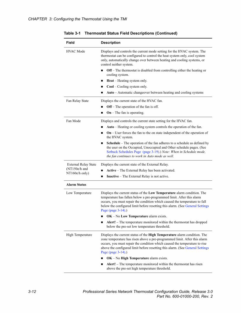
HVAC Mode Displays and controls the current mode setting for the HVAC system. The thermostat can be configured to control the heat system only, cool system only, automatically change over between heating and cooling systems, or control neither system.
Off – The thermostat is disabled from controlling either the heating or cooling system.
Heat – Heating system only.
Cool – Cooling system only.
Auto – Automatic changeover between heating and cooling systems
Fan Relay State Displays the current state of the HVAC fan.
Off – The operation of the fan is off.
On – The fan is operating.
Fan Mode Displays and controls the current state setting for the HVAC fan.
Auto – Heating or cooling system controls the operation of the fan.
On – User forces the fan to the on state independent of the operation of the HVAC system.
Schedule – The operation of the fan adheres to a schedule as defined by the user on the Occupied, Unoccupied and Other schedule pages. (See Setback Schedules Page (page 3-19).) Note: When in Schedule mode, the fan continues to work in Auto mode as well.
External Relay State(NT150e/h and NT160e/h only)
Displays the current state of the External Relay.
Active – The External Relay has been activated.
Inactive – The External Relay is not active.
Alarm Status
Low Temperature Displays the current status of the Low Temperature alarm condition. The temperature has fallen below a pre-programmed limit. After this alarm occurs, you must repair the condition which caused the temperature to fall below the configured limit before resetting this alarm. (See General Settings Page (page 3-14).)
OK – No Low Temperature alarm exists.
Alert! – The temperature monitored within the thermostat has dropped below the pre-set low temperature threshold.
High Temperature Displays the current status of the High Temperature alarm condition. The zone temperature has risen above a pre-programmed limit. After this alarm occurs, you must repair the condition which caused the temperature to rise above the configured limit before resetting this alarm. (See General Settings Page (page 3-14).)
OK – No High Temperature alarm exists.
Alert! – The temperature monitored within the thermostat has risen above the pre-set high temperature threshold.
Table 3-1 Thermostat Status Field Descriptions (Continued)
Field Description
Beta Draft ConfidentialStatus & Control Page
Professional Series Network Thermostat Configuration Guide, Release 3.0 3-13Part No. 600-01000-200, Rev. 2
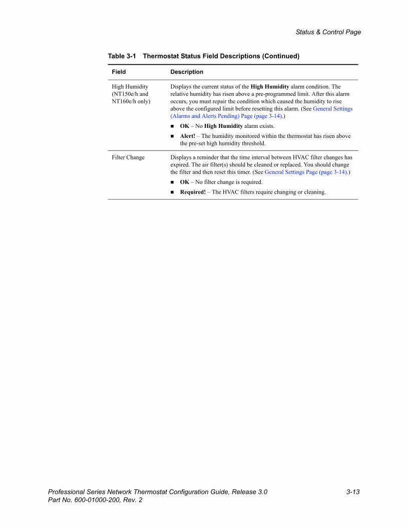
High Humidity (NT150e/h and NT160e/h only)
Displays the current status of the High Humidity alarm condition. The relative humidity has risen above a pre-programmed limit. After this alarm occurs, you must repair the condition which caused the humidity to rise above the configured limit before resetting this alarm. (See General Settings (Alarms and Alerts Pending) Page (page 3-14).)
OK – No High Humidity alarm exists.
Alert! – The humidity monitored within the thermostat has risen above the pre-set high humidity threshold.
Filter Change Displays a reminder that the time interval between HVAC filter changes has expired. The air filter(s) should be cleaned or replaced. You should change the filter and then reset this timer. (See General Settings Page (page 3-14).)
OK – No filter change is required.
Required! – The HVAC filters require changing or cleaning.
Table 3-1 Thermostat Status Field Descriptions (Continued)
Field Description
Beta Draft Confidential
3-14 Professional Series Network Thermostat Configuration Guide, Release 3.0Part No. 600-01000-200, Rev. 2
CHAPTER 3: Configuring the Thermostat Using the TMI
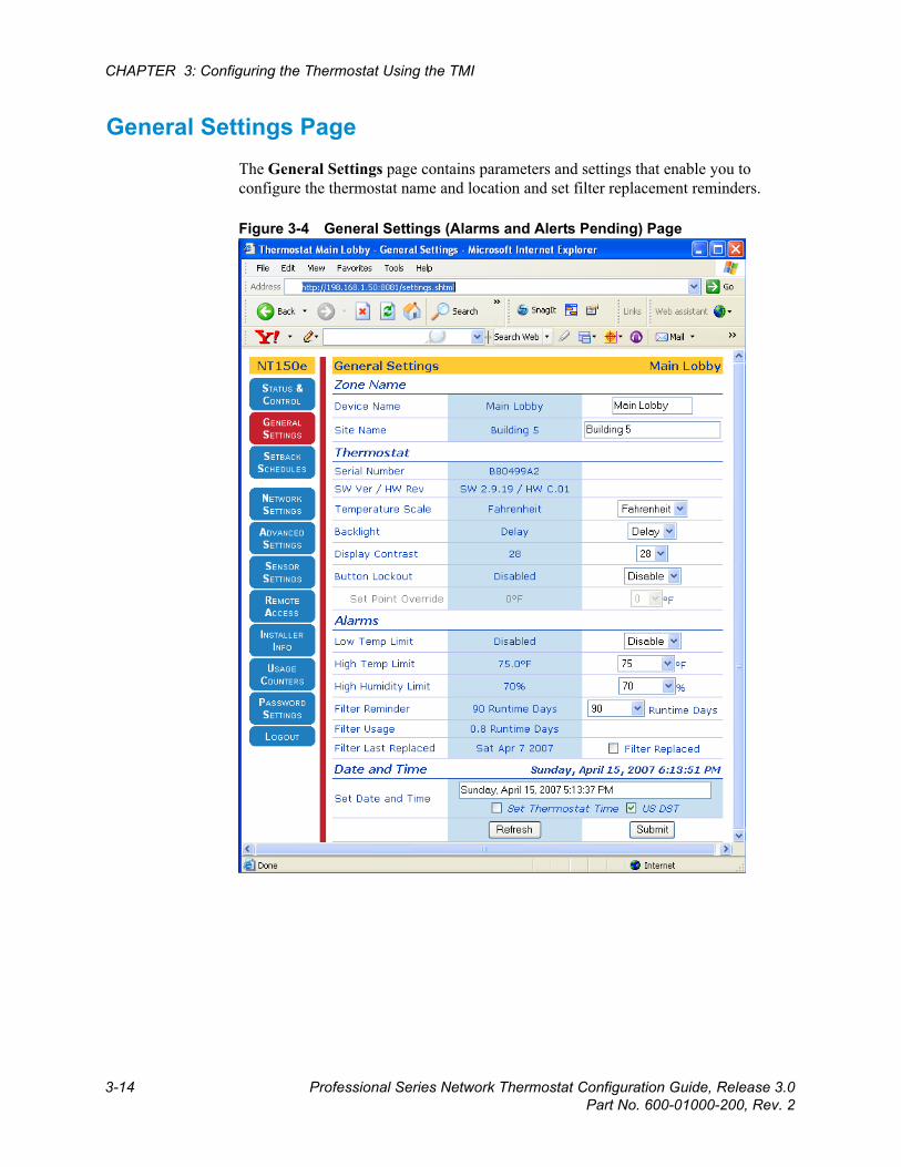
General Settings PageThe General Settings page contains parameters and settings that enable you to configure the thermostat name and location and set filter replacement reminders.
Figure 3-4 General Settings (Alarms and Alerts Pending) Page
Beta Draft ConfidentialGeneral Settings Page
Professional Series Network Thermostat Configuration Guide, Release 3.0 3-15Part No. 600-01000-200, Rev. 2
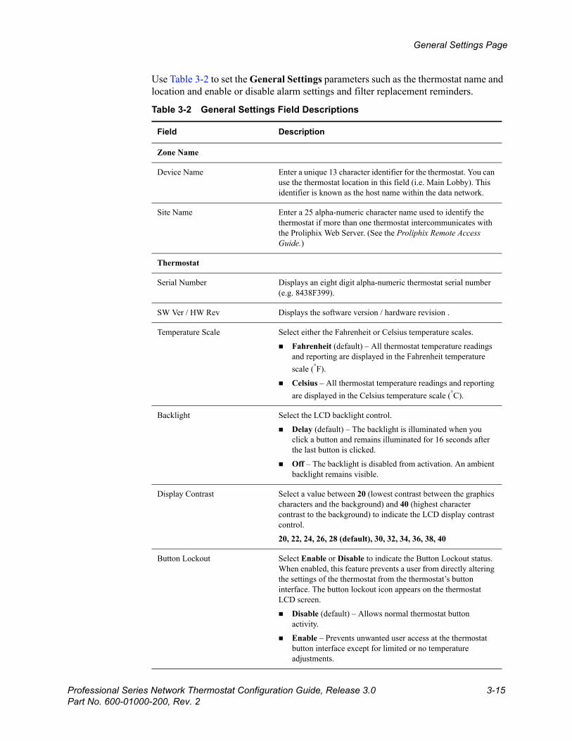
Use Table 3-2 to set the General Settings parameters such as the thermostat name and location and enable or disable alarm settings and filter replacement reminders.
Table 3-2 General Settings Field Descriptions
Field Description
Zone Name
Device Name Enter a unique 13 character identifier for the thermostat. You can use the thermostat location in this field (i.e. Main Lobby). This identifier is known as the host name within the data network.
Site Name Enter a 25 alpha-numeric character name used to identify the thermostat if more than one thermostat intercommunicates with the Proliphix Web Server. (See the Proliphix Remote Access Guide.)
Thermostat
Serial Number Displays an eight digit alpha-numeric thermostat serial number (e.g. 8438F399).
SW Ver / HW Rev Displays the software version / hardware revision .
Temperature Scale Select either the Fahrenheit or Celsius temperature scales.
Fahrenheit (default) – All thermostat temperature readings and reporting are displayed in the Fahrenheit temperature scale (°F).
Celsius – All thermostat temperature readings and reporting are displayed in the Celsius temperature scale (°C).
Backlight Select the LCD backlight control.
Delay (default) – The backlight is illuminated when you click a button and remains illuminated for 16 seconds after the last button is clicked.
Off – The backlight is disabled from activation. An ambient backlight remains visible.
Display Contrast Select a value between 20 (lowest contrast between the graphics characters and the background) and 40 (highest character contrast to the background) to indicate the LCD display contrast control.
20, 22, 24, 26, 28 (default), 30, 32, 34, 36, 38, 40
Button Lockout Select Enable or Disable to indicate the Button Lockout status. When enabled, this feature prevents a user from directly altering the settings of the thermostat from the thermostat’s button interface. The button lockout icon appears on the thermostat LCD screen.
Disable (default) – Allows normal thermostat button activity.
Enable – Prevents unwanted user access at the thermostat button interface except for limited or no temperature adjustments.

Beta Draft Confidential
3-16 Professional Series Network Thermostat Configuration Guide, Release 3.0Part No. 600-01000-200, Rev. 2
CHAPTER 3: Configuring the Thermostat Using the TMI
Set Point Override This feature, when used with Button Lockout restricts the use of the thermostat buttons to allow only limited temperature adjustments to be made above and below the preset temperature schedules. This field is disabled if Button Lockout is set to Disable.
0 (default) – No temperature adjustments are allowed. All thermostat buttons are disabled.
1 through 20 – (Fahrenheit) Allowed temperature limits above and below the current scheduled temperature settings. (e.g. If this value is set to 2, the Up and Down buttons may be used to select a temperature within the range of 2°F below/above the current scheduled temperature set point.)
.5 through 10 – (Celsius) Allowed temperature limits above and below the current scheduled temperature settings.
Alarms
Low Temp(erature) Limit Select a value or Disable to indicate the low temperature threshold detection status. The value set by this parameter is monitored by the thermostat and compared against the current Zone Temperature. If the current Zone Temperature falls below this value, an alarm condition is set and the status is displayed on the Status & Control Page (page 3-9). In addition, this alarm will be sent to the Proliphix web site to trigger an email notification if this function is Enabled.
Disable (default) – No low temperature limit is set.
-30°F(-34.5°C) to 200°F(93°C)
This is a major (red) alarm condition.
Low Temp(erature) Dismiss If a Low Temp Limit alarm is set and is noted in the Low Temp Dismiss field then the Condition Repaired box must be checked and the Zone Temperature must be above the Low Temp Limit or the Low Temp Limit must be set to Disable for the alarm condition to be cleared upon a Submit.
High Temp(erature) Limit Select a value or Disable to indicate the high temperature threshold detection status. The value set by this parameter is monitored by the thermostat and compared against the current Zone Temperature. If the current Zone Temperature rises above this value, an alarm condition is set and the status is displayed on the Status & Control Page (page 3-9). In addition, this alarm is sent to the Proliphix web site to trigger an email notification if this function is Enabled.
Disable (default) – No high temperature limit is set.
-30°F(-34.5°C) to 200°F(93°C)
This is a major (red) alarm condition.
Table 3-2 General Settings Field Descriptions (Continued)
Field Description
Beta Draft ConfidentialGeneral Settings Page
Professional Series Network Thermostat Configuration Guide, Release 3.0 3-17Part No. 600-01000-200, Rev. 2
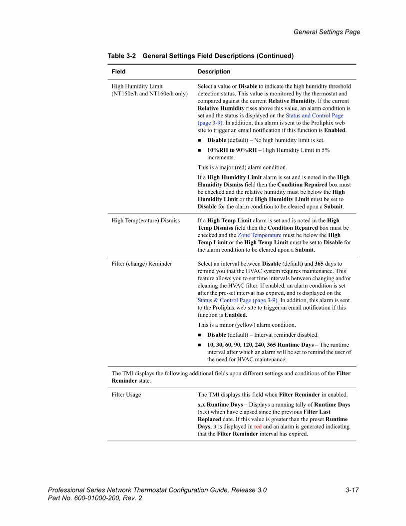
High Humidity Limit (NT150e/h and NT160e/h only)
Select a value or Disable to indicate the high humidity threshold detection status. This value is monitored by the thermostat and compared against the current Relative Humidity. If the current Relative Humidity rises above this value, an alarm condition is set and the status is displayed on the Status and Control Page (page 3-9). In addition, this alarm is sent to the Proliphix web site to trigger an email notification if this function is Enabled.
Disable (default) – No high humidity limit is set.
10%RH to 90%RH – High Humidity Limit in 5% increments.
This is a major (red) alarm condition.
If a High Humidity Limit alarm is set and is noted in the High Humidity Dismiss field then the Condition Repaired box must be checked and the relative humidity must be below the High Humidity Limit or the High Humidity Limit must be set to Disable for the alarm condition to be cleared upon a Submit.
High Temp(erature) Dismiss If a High Temp Limit alarm is set and is noted in the High Temp Dismiss field then the Condition Repaired box must be checked and the Zone Temperature must be below the High Temp Limit or the High Temp Limit must be set to Disable for the alarm condition to be cleared upon a Submit.
Filter (change) Reminder Select an interval between Disable (default) and 365 days to remind you that the HVAC system requires maintenance. This feature allows you to set time intervals between changing and/or cleaning the HVAC filter. If enabled, an alarm condition is set after the pre-set interval has expired, and is displayed on the Status & Control Page (page 3-9). In addition, this alarm is sent to the Proliphix web site to trigger an email notification if this function is Enabled.
This is a minor (yellow) alarm condition.
Disable (default) – Interval reminder disabled.
10, 30, 60, 90, 120, 240, 365 Runtime Days – The runtime interval after which an alarm will be set to remind the user of the need for HVAC maintenance.
The TMI displays the following additional fields upon different settings and conditions of the Filter Reminder state.
Filter Usage The TMI displays this field when Filter Reminder in enabled.
x.x Runtime Days – Displays a running tally of Runtime Days (x.x) which have elapsed since the previous Filter Last Replaced date. If this value is greater than the preset Runtime Days, it is displayed in red and an alarm is generated indicating that the Filter Reminder interval has expired.
Table 3-2 General Settings Field Descriptions (Continued)
Field Description
Beta Draft Confidential
3-18 Professional Series Network Thermostat Configuration Guide, Release 3.0Part No. 600-01000-200, Rev. 2
CHAPTER 3: Configuring the Thermostat Using the TMI
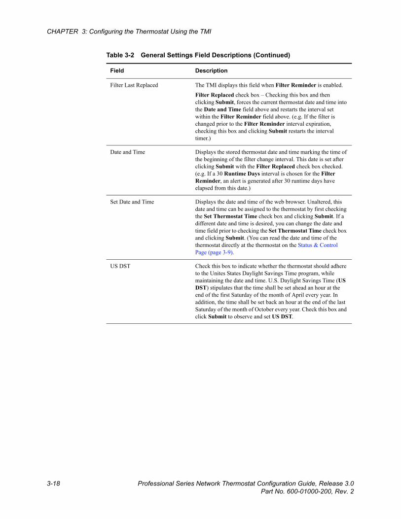
Filter Last Replaced The TMI displays this field when Filter Reminder is enabled.
Filter Replaced check box – Checking this box and then clicking Submit, forces the current thermostat date and time into the Date and Time field above and restarts the interval set within the Filter Reminder field above. (e.g. If the filter is changed prior to the Filter Reminder interval expiration, checking this box and clicking Submit restarts the interval timer.)
Date and Time Displays the stored thermostat date and time marking the time of the beginning of the filter change interval. This date is set after clicking Submit with the Filter Replaced check box checked. (e.g. If a 30 Runtime Days interval is chosen for the Filter Reminder, an alert is generated after 30 runtime days have elapsed from this date.)
Set Date and Time Displays the date and time of the web browser. Unaltered, this date and time can be assigned to the thermostat by first checking the Set Thermostat Time check box and clicking Submit. If a different date and time is desired, you can change the date and time field prior to checking the Set Thermostat Time check box and clicking Submit. (You can read the date and time of the thermostat directly at the thermostat on the Status & Control Page (page 3-9).
US DST Check this box to indicate whether the thermostat should adhere to the Unites States Daylight Savings Time program, while maintaining the date and time. U.S. Daylight Savings Time (US DST) stipulates that the time shall be set ahead an hour at the end of the first Saturday of the month of April every year. In addition, the time shall be set back an hour at the end of the last Saturday of the month of October every year. Check this box and click Submit to observe and set US DST.
Table 3-2 General Settings Field Descriptions (Continued)
Field Description
Beta Draft ConfidentialSetback Schedules Page
Professional Series Network Thermostat Configuration Guide, Release 3.0 3-19Part No. 600-01000-200, Rev. 2
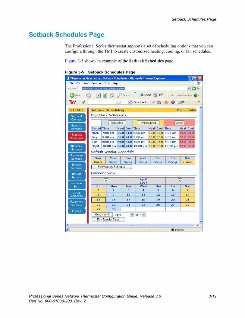
Setback Schedules Page The Professional Series thermostat supports a set of scheduling options that you can configure through the TMI to create customized heating, cooling, or fan schedules.
Figure 3-5 shows an example of the Setback Schedules page.
Figure 3-5 Setback Schedules Page
Beta Draft Confidential
3-20 Professional Series Network Thermostat Configuration Guide, Release 3.0Part No. 600-01000-200, Rev. 2
CHAPTER 3: Configuring the Thermostat Using the TMI
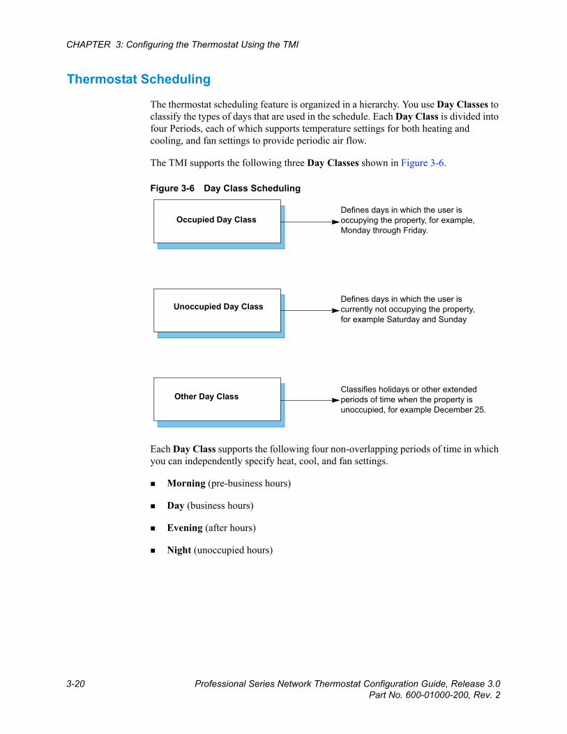
Thermostat Scheduling
The thermostat scheduling feature is organized in a hierarchy. You use Day Classes to classify the types of days that are used in the schedule. Each Day Class is divided into four Periods, each of which supports temperature settings for both heating and cooling, and fan settings to provide periodic air flow.
The TMI supports the following three Day Classes shown in Figure 3-6.
Figure 3-6 Day Class Scheduling
Each Day Class supports the following four non-overlapping periods of time in which you can independently specify heat, cool, and fan settings.
Morning (pre-business hours)
Day (business hours)
Evening (after hours)
Night (unoccupied hours)
Defines days in which the user is occupying the property, for example, Monday through Friday.
Defines days in which the user is currently not occupying the property, for example Saturday and Sunday
Classifies holidays or other extended periods of time when the property is unoccupied, for example December 25.
Unoccupied Day Class
Occupied Day Class
Other Day Class
Beta Draft ConfidentialSetback Schedules Page
Professional Series Network Thermostat Configuration Guide, Release 3.0 3-21Part No. 600-01000-200, Rev. 2
Day Class Schedules
Figure 3-5 on page 3-19 displays Occupied, Unoccupied, and Other Day Class Schedules in the Day Class Schedules table. The TMI displays the day class periods and period start times within each row of the table. The TMI also displays the heat and cool settings for each period in each day class. Although the thermostat ships from the factory with pre-set day class period temperature settings, you can change these settings by clicking on the Day Class heading (i.e. Occupied, Unoccupied, and Other).
Default Weekly Schedule
In Figure 3-5 on page 3-19, the Default Weekly Schedule table provides a template that you can use to apply the three day classes to each day of the week, for every week of the year. The TMI applies this weekly template to every week in each month that is visible in the Calendar View table at the bottom of the Setback Schedules Page (page 3-19).
To edit the Default Weekly Schedule, click Edit Weekly Schedule and continue with Default Weekly Schedule (page 3-24).
Calendar View
The Calendar View table displays the day class settings for each day of the month. You can modify any day class in the Calendar View table using any of the following three methods:
Click on the date within the calendar and continue with Schedule Special Days on page 3-25.
Click Edit Special Days and continue with Schedule Special Days on page 3-25.
NoteYou can edit the Day Class headings on the NT130e/h and NT160e/h models only by highlighting the heading and entering a new heading. Each heading may contain a maximum of 10 characters and the Default Weekly Schedule table displays up to the first 5 characters of the assigned heading.
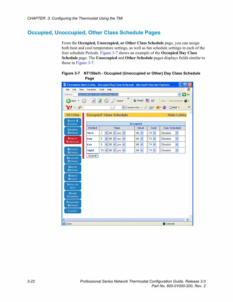
Beta Draft Confidential
3-22 Professional Series Network Thermostat Configuration Guide, Release 3.0Part No. 600-01000-200, Rev. 2
CHAPTER 3: Configuring the Thermostat Using the TMI
Occupied, Unoccupied, Other Class Schedule Pages
From the Occupied, Unoccupied, or Other Class Schedule page, you can assign both heat and cool temperature settings, as well as fan schedule settings in each of the four schedule Periods. Figure 3-7 shows an example of the Occupied Day Class Schedule page. The Unoccupied and Other Schedule pages displays fields similar to those in Figure 3-7.
Figure 3-7 NT150e/h - Occupied (Unoccupied or Other) Day Class Schedule Page
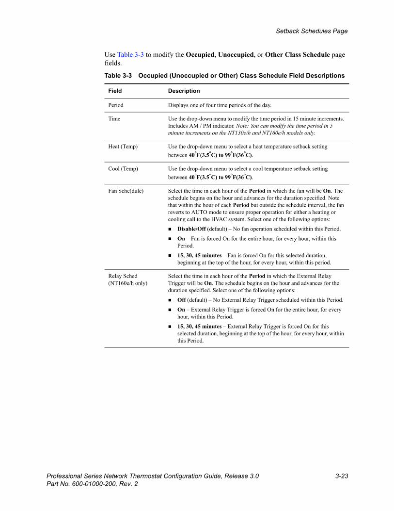
Beta Draft ConfidentialSetback Schedules Page
Professional Series Network Thermostat Configuration Guide, Release 3.0 3-23Part No. 600-01000-200, Rev. 2
Use Table 3-3 to modify the Occupied, Unoccupied, or Other Class Schedule page fields.
Table 3-3 Occupied (Unoccupied or Other) Class Schedule Field Descriptions
Field Description
Period Displays one of four time periods of the day.
Time Use the drop-down menu to modify the time period in 15 minute increments. Includes AM / PM indicator. Note: You can modify the time period in 5 minute increments on the NT130e/h and NT160e/h models only.
Heat (Temp) Use the drop-down menu to select a heat temperature setback setting between 40°F(3.5°C) to 99°F(36°C).
Cool (Temp) Use the drop-down menu to select a cool temperature setback setting between 40°F(3.5°C) to 99°F(36°C).
Fan Sche(dule) Select the time in each hour of the Period in which the fan will be On. The schedule begins on the hour and advances for the duration specified. Note that within the hour of each Period but outside the schedule interval, the fan reverts to AUTO mode to ensure proper operation for either a heating or cooling call to the HVAC system. Select one of the following options:
Disable/Off (default) – No fan operation scheduled within this Period.
On – Fan is forced On for the entire hour, for every hour, within this Period.
15, 30, 45 minutes – Fan is forced On for this selected duration, beginning at the top of the hour, for every hour, within this period.
Relay Sched(NT160e/h only)
Select the time in each hour of the Period in which the External Relay Trigger will be On. The schedule begins on the hour and advances for the duration specified. Select one of the following options:
Off (default) – No External Relay Trigger scheduled within this Period.
On – External Relay Trigger is forced On for the entire hour, for every hour, within this Period.
15, 30, 45 minutes – External Relay Trigger is forced On for this selected duration, beginning at the top of the hour, for every hour, within this Period.
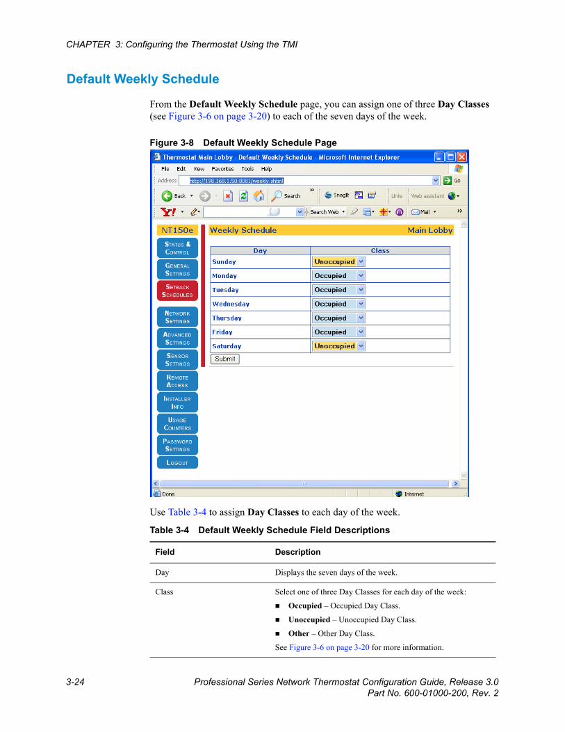
Beta Draft Confidential
3-24 Professional Series Network Thermostat Configuration Guide, Release 3.0Part No. 600-01000-200, Rev. 2
CHAPTER 3: Configuring the Thermostat Using the TMI
Default Weekly Schedule
From the Default Weekly Schedule page, you can assign one of three Day Classes (see Figure 3-6 on page 3-20) to each of the seven days of the week.
Figure 3-8 Default Weekly Schedule Page
Use Table 3-4 to assign Day Classes to each day of the week.
Table 3-4 Default Weekly Schedule Field Descriptions
Field Description
Day Displays the seven days of the week.
Class Select one of three Day Classes for each day of the week:
Occupied – Occupied Day Class.
Unoccupied – Unoccupied Day Class.
Other – Other Day Class.
See Figure 3-6 on page 3-20 for more information.
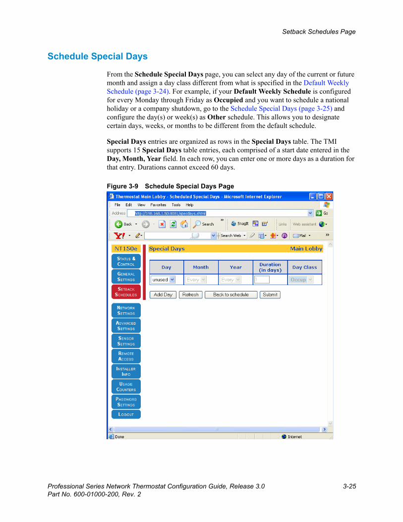
Beta Draft ConfidentialSetback Schedules Page
Professional Series Network Thermostat Configuration Guide, Release 3.0 3-25Part No. 600-01000-200, Rev. 2
Schedule Special Days
From the Schedule Special Days page, you can select any day of the current or future month and assign a day class different from what is specified in the Default Weekly Schedule (page 3-24). For example, if your Default Weekly Schedule is configured for every Monday through Friday as Occupied and you want to schedule a national holiday or a company shutdown, go to the Schedule Special Days (page 3-25) and configure the day(s) or week(s) as Other schedule. This allows you to designate certain days, weeks, or months to be different from the default schedule.
Special Days entries are organized as rows in the Special Days table. The TMI supports 15 Special Days table entries, each comprised of a start date entered in the Day, Month, Year field. In each row, you can enter one or more days as a duration for that entry. Durations cannot exceed 60 days.
Figure 3-9 Schedule Special Days Page
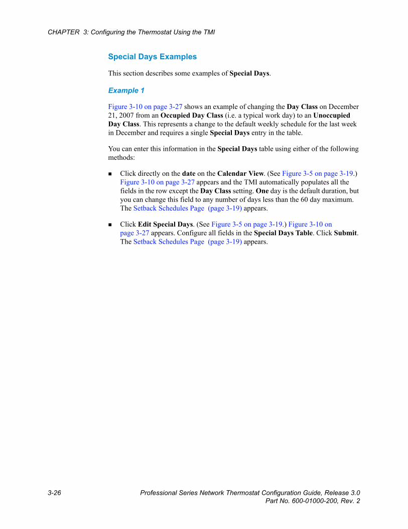
Beta Draft Confidential
3-26 Professional Series Network Thermostat Configuration Guide, Release 3.0Part No. 600-01000-200, Rev. 2
CHAPTER 3: Configuring the Thermostat Using the TMI
Special Days Examples
This section describes some examples of Special Days.
Example 1
Figure 3-10 on page 3-27 shows an example of changing the Day Class on December 21, 2007 from an Occupied Day Class (i.e. a typical work day) to an Unoccupied Day Class. This represents a change to the default weekly schedule for the last week in December and requires a single Special Days entry in the table.
You can enter this information in the Special Days table using either of the following methods:
Click directly on the date on the Calendar View. (See Figure 3-5 on page 3-19.) Figure 3-10 on page 3-27 appears and the TMI automatically populates all the fields in the row except the Day Class setting. One day is the default duration, but you can change this field to any number of days less than the 60 day maximum. The Setback Schedules Page (page 3-19) appears.
Click Edit Special Days. (See Figure 3-5 on page 3-19.) Figure 3-10 on page 3-27 appears. Configure all fields in the Special Days Table. Click Submit. The Setback Schedules Page (page 3-19) appears.
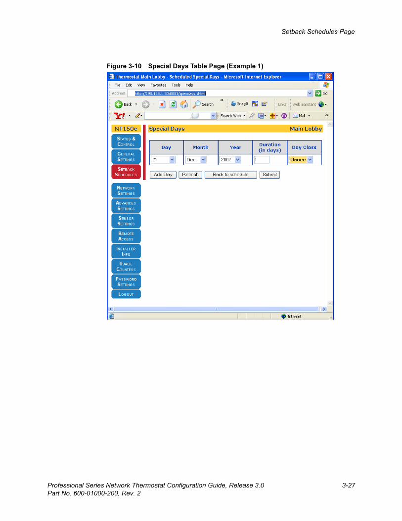
Beta Draft ConfidentialSetback Schedules Page
Professional Series Network Thermostat Configuration Guide, Release 3.0 3-27Part No. 600-01000-200, Rev. 2
Figure 3-10 Special Days Table Page (Example 1)
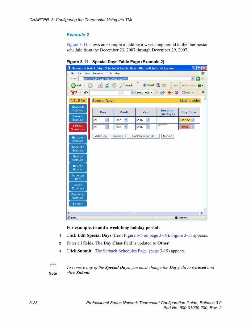
Beta Draft Confidential
3-28 Professional Series Network Thermostat Configuration Guide, Release 3.0Part No. 600-01000-200, Rev. 2
CHAPTER 3: Configuring the Thermostat Using the TMI
Example 2
Figure 3-11 shows an example of adding a week-long period to the thermostat schedule from the December 23, 2007 through December 29, 2007.
Figure 3-11 Special Days Table Page (Example 2)
For example, to add a week-long holiday period:
1 Click Edit Special Days (from Figure 3-5 on page 3-19). Figure 3-11 appears.
2 Enter all fields. The Day Class field is updated to Other.
3 Click Submit. The Setback Schedules Page (page 3-19) appears.
NoteTo remove any of the Special Days, you must change the Day field to Unused and click Submit.

Beta Draft ConfidentialSetback Schedules Page
Professional Series Network Thermostat Configuration Guide, Release 3.0 3-29Part No. 600-01000-200, Rev. 2
The Setback Schedules Page now displays the two Special Days entries in the Calendar View.
Figure 3-12 Setback Schedules Page

Beta Draft Confidential
3-30 Professional Series Network Thermostat Configuration Guide, Release 3.0Part No. 600-01000-200, Rev. 2
CHAPTER 3: Configuring the Thermostat Using the TMI
Network Settings Page From the Network Settings Page, you can configure the appropriate network parameters specific to your local network such as configuring the Syslog server address to receive messages and alerts.
Figure 3-13 Network Settings Page

Beta Draft ConfidentialNetwork Settings Page
Professional Series Network Thermostat Configuration Guide, Release 3.0 3-31Part No. 600-01000-200, Rev. 2
Use Table 3-5 to configure the Network Settings fields.
Table 3-5 Network Settings Field Descriptions
Field Description
Addressing
MAC Address Displays a factory assigned value installed in the thermostat which uniquely identifies the thermostat on the local network for transmitting and receiving network information.
The system displays the MAC address in the format of 00:11:49:AB:CD:EF, where AB:CD:EF is a unique value for each thermostat.
IP Address Method Select the method by which the thermostat receives the unique Internet Protocol address for the local network. IP addressing can be either automatically assigned via a local DHCP server or manually (Static) assigned by the user. (See DHCP Assigned IP Addresses (page 3-2).)
DHCP (default) – IP addressing method is DHCP assigned.
Static – IP address is manually assigned by the user.
After the initial configuration of the thermostat, you should assign IP address to Static to ensure a permanent IP address assignment for remote access or for simplified local access.
IP Address Displays the unique Internet Protocol address either assigned statically or by DHCP. (See IP Address Method.) (You must click Submit after changing this parameter to invoke a software reset to set the new value.)
A.B.C.D – Four field standard dot notation for IP address designation.
Subnet Mask Enter the IP subnet on which the thermostat IP address is assigned. The subnet can include 256, 65536 or 16772216 IP addresses. (You must click Submit after changing this parameter to invoke a software reset to set the new value.) Subnet Mask options include:
X.Y.Z.C – Class C address subnet. There can be 256 IP addresses in this subnet.
X.Y.B.B – Class B address subnet. There can be 65,536 IP addresses in this subnet.
X.A.A.A – Class A address subnet. There can be 16,772,216 IP addresses in this subnet.
Gateway (Address) Enter the IP address of the router which acts as a gateway for the thermostats to communicate to other devices in another subnet. The thermostat uses this address when it needs to communicate with the Proliphix Web Server for remote access. (You must click Submit after changing this parameter to invoke a software reset to set the new value.)
A.B.C.D – Four field standard dot notation for IP address designation.
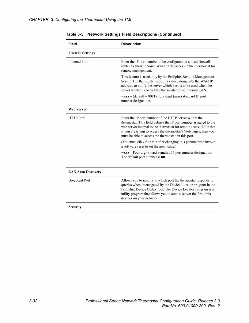
Beta Draft Confidential
3-32 Professional Series Network Thermostat Configuration Guide, Release 3.0Part No. 600-01000-200, Rev. 2
CHAPTER 3: Configuring the Thermostat Using the TMI
Firewall Settings
Inbound Port Enter the IP port number to be configured on a local firewall router to allow inbound WAN traffic access to the thermostat for remote management.
This feature is used only by the Proliphix Remote Management Server. The thermostat uses this value, along with the WAN IP address, to notify the server which port is to be used when the server wants to contact the thermostat on an internal LAN.
wxyz – (default = 8081) Four digit (max) standard IP port number designation.
Web Server
HTTP Port Enter the IP port number of the HTTP server within the thermostat. This field defines the IP port number assigned to the web server internal to the thermostat for remote access. Note that if you are trying to access the thermostat’s Web pages, then you must be able to access the thermostat on this port.
(You must click Submit after changing this parameter to invoke a software reset to set the new value.)
wxyz – Four digit (max) standard IP port number designation. The default port number is 80.
LAN Auto-Discovery
Broadcast Port Allows you to specify to which port the thermostat responds to queries when interrogated by the Device Locator program in the Proliphix Device Utility tool. The Device Locator Program is a utility program that allows you to auto-discover the Proliphix devices on your network.
Security
Table 3-5 Network Settings Field Descriptions (Continued)
Field Description

Beta Draft ConfidentialNetwork Settings Page
Professional Series Network Thermostat Configuration Guide, Release 3.0 3-33Part No. 600-01000-200, Rev. 2
Access Filter Select the check box to enable Access Filters. The Access Filter restricts access to the thermostat from network devices whose IP addresses are outside the range specified in the accompanying fields. Network administrators can provision varying levels of security based on combinations of the administrator/user passwords as well as these address filter levels. If both of these option levels are disabled (unchecked), the thermostat is exposed to access from all network devices located anywhere in the IP address space and is only protected with user/admin password authentication.
Local Subnet – (default is unchecked) The thermostat can be accessed within a class C subnet. (e.g. 192.168.111.x where “x” is 0 to 254)
User Defined – (default is unchecked) The thermostat can be accessed by network devices which reside in the address space as specified by both the Network Address and Network Mask fields. This option is typically used in corporate environments with large LANs which include many routed subnets.
Network Address If the User Defined Access Filter is selected, this field displays the unique Internet Protocol address required in conjunction with the Network Mask to allow network accesses.
A.B.C.D – Four field standard dot notation for IP address designation.
Network Mask If the User Defined Access Filter is selected, this field displays the network mask required in conjunction with the Network Address to allow network accesses. This field defines the IP subnet from which network accesses is allowed. The subnet can include 256, 65536 or 16772216 IP addresses.
X.Y.Z.C – Class C address subnet. There can be 255 IP addresses in this subnet.
X.Y.B.B – Class B address subnet. There can be 65,536 IP addresses in this subnet.
X.A.A.A – Class A address subnet. There can be 16,772,216 IP addresses in this subnet.
Syslog Setup
Address Enter the Syslog server IP address. The IP address can be either a single address, multicast, or broadcast address.
A.B.C.D – Four field standard dot notation for IP address designation.
Alarms that are delivered to the Proliphix Remote Management Server are also delivered to the Syslog server. The alarm status is delivered to the Proliphix Remote Management Server independent of the Syslog messages. Note that you can disable Syslog messages by setting either the destination IP address or port address to zero (0.0.0.0 or 0).
Table 3-5 Network Settings Field Descriptions (Continued)
Field Description
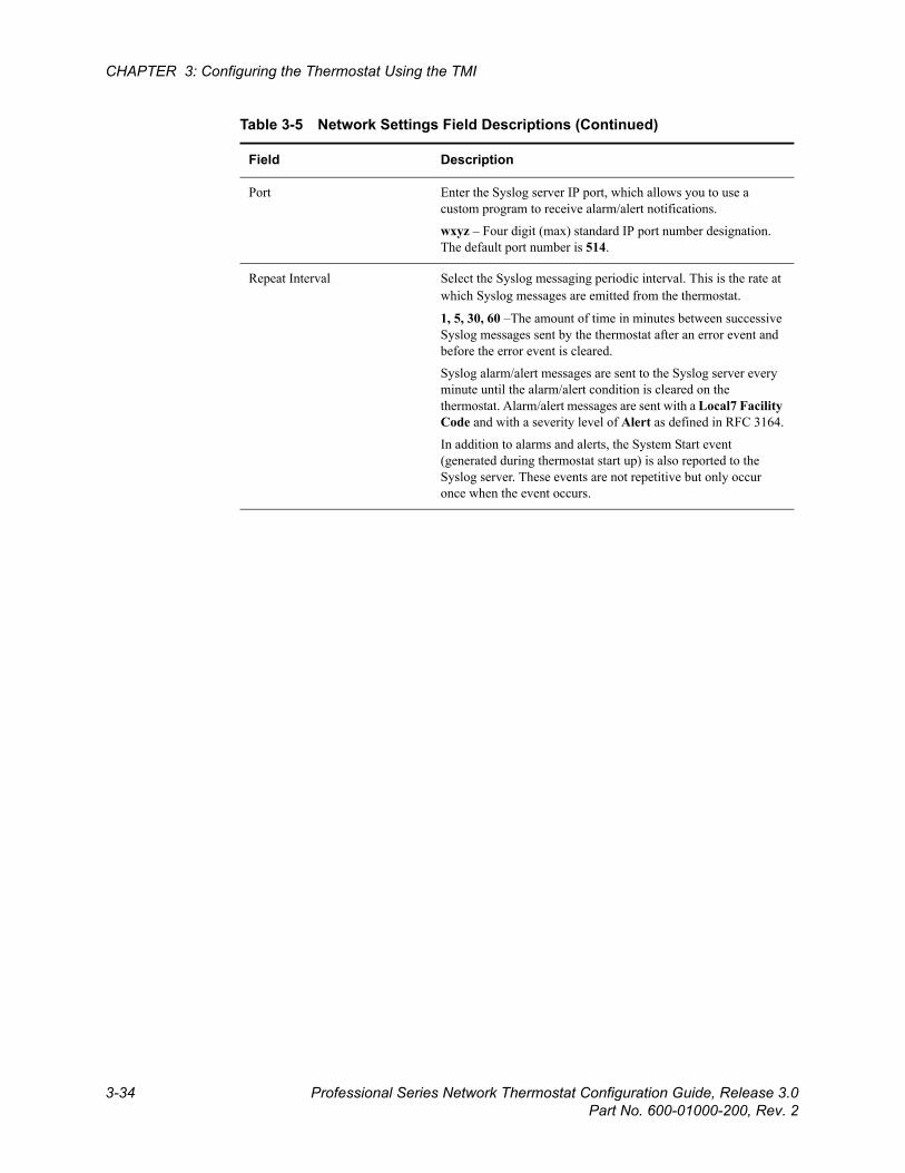
Beta Draft Confidential
3-34 Professional Series Network Thermostat Configuration Guide, Release 3.0Part No. 600-01000-200, Rev. 2
CHAPTER 3: Configuring the Thermostat Using the TMI
Port Enter the Syslog server IP port, which allows you to use a custom program to receive alarm/alert notifications.
wxyz – Four digit (max) standard IP port number designation. The default port number is 514.
Repeat Interval Select the Syslog messaging periodic interval. This is the rate at which Syslog messages are emitted from the thermostat.
1, 5, 30, 60 –The amount of time in minutes between successive Syslog messages sent by the thermostat after an error event and before the error event is cleared.
Syslog alarm/alert messages are sent to the Syslog server every minute until the alarm/alert condition is cleared on the thermostat. Alarm/alert messages are sent with a Local7 Facility Code and with a severity level of Alert as defined in RFC 3164.
In addition to alarms and alerts, the System Start event (generated during thermostat start up) is also reported to the Syslog server. These events are not repetitive but only occur once when the event occurs.
Table 3-5 Network Settings Field Descriptions (Continued)
Field Description
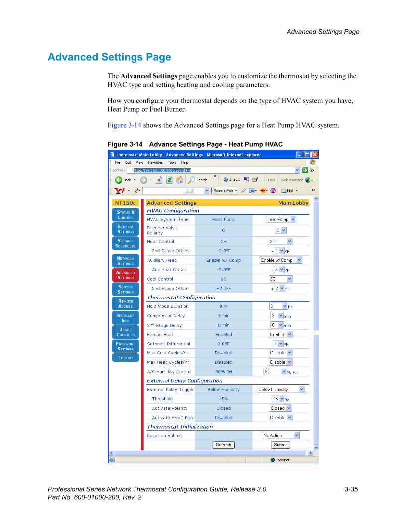
Beta Draft ConfidentialAdvanced Settings Page
Professional Series Network Thermostat Configuration Guide, Release 3.0 3-35Part No. 600-01000-200, Rev. 2
Advanced Settings PageThe Advanced Settings page enables you to customize the thermostat by selecting the HVAC type and setting heating and cooling parameters.
How you configure your thermostat depends on the type of HVAC system you have, Heat Pump or Fuel Burner.
Figure 3-14 shows the Advanced Settings page for a Heat Pump HVAC system.
Figure 3-14 Advance Settings Page - Heat Pump HVAC
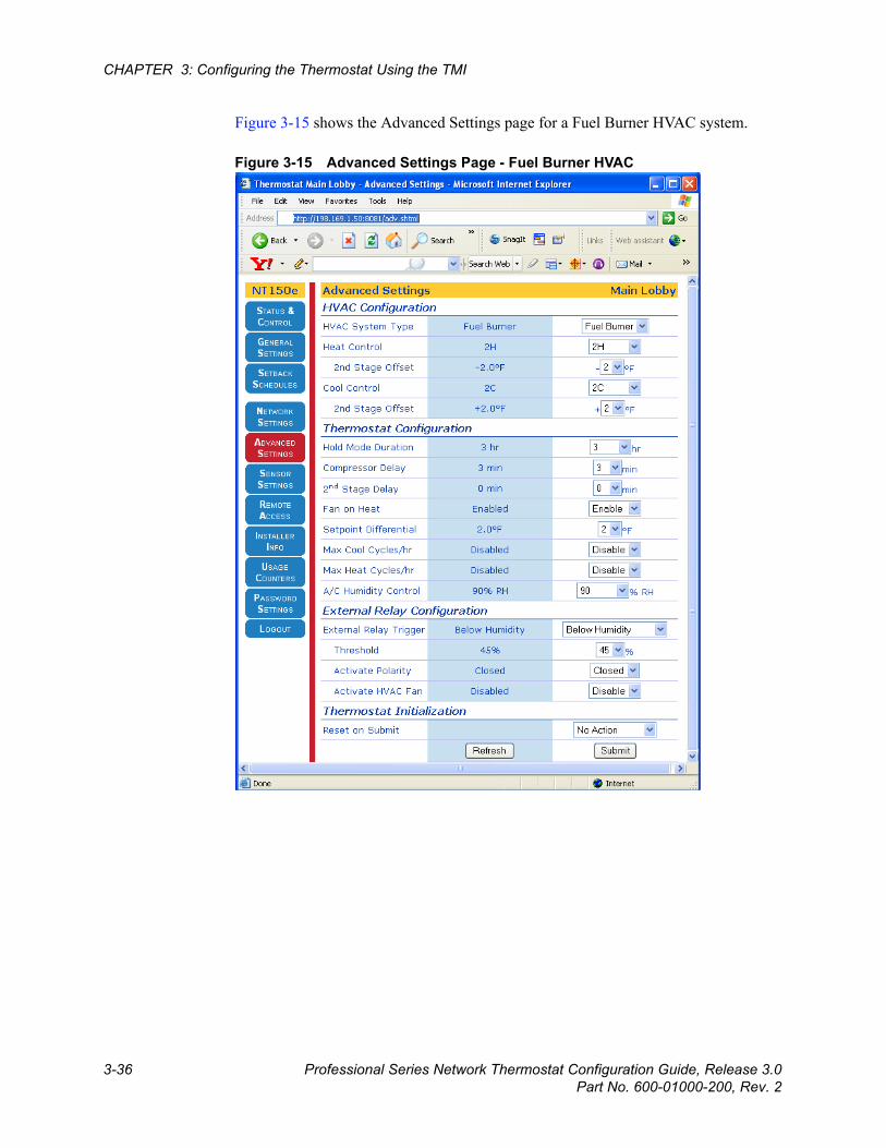
Beta Draft Confidential
3-36 Professional Series Network Thermostat Configuration Guide, Release 3.0Part No. 600-01000-200, Rev. 2
CHAPTER 3: Configuring the Thermostat Using the TMI
Figure 3-15 shows the Advanced Settings page for a Fuel Burner HVAC system.
Figure 3-15 Advanced Settings Page - Fuel Burner HVAC
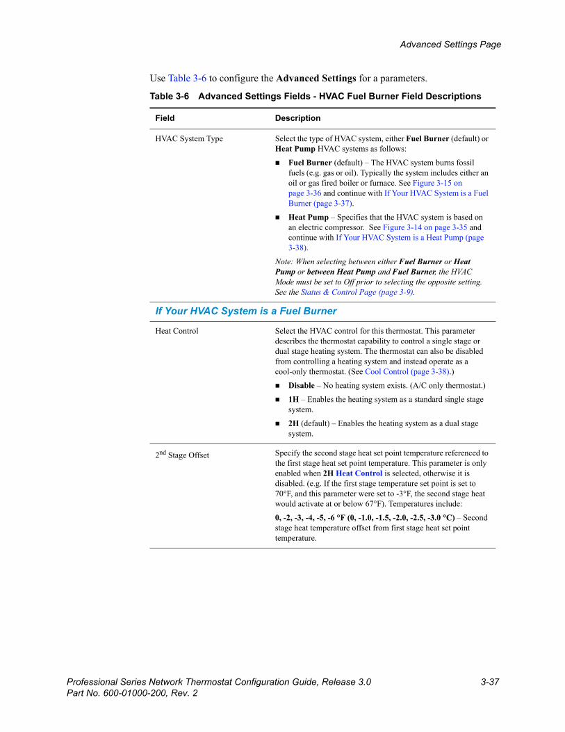
Beta Draft ConfidentialAdvanced Settings Page
Professional Series Network Thermostat Configuration Guide, Release 3.0 3-37Part No. 600-01000-200, Rev. 2
Use Table 3-6 to configure the Advanced Settings for a parameters.
Table 3-6 Advanced Settings Fields - HVAC Fuel Burner Field Descriptions
Field Description
HVAC System Type Select the type of HVAC system, either Fuel Burner (default) or Heat Pump HVAC systems as follows:
Fuel Burner (default) – The HVAC system burns fossil fuels (e.g. gas or oil). Typically the system includes either an oil or gas fired boiler or furnace. See Figure 3-15 on page 3-36 and continue with If Your HVAC System is a Fuel Burner (page 3-37).
Heat Pump – Specifies that the HVAC system is based on an electric compressor. See Figure 3-14 on page 3-35 and continue with If Your HVAC System is a Heat Pump (page 3-38).
Note: When selecting between either Fuel Burner or Heat Pump or between Heat Pump and Fuel Burner, the HVAC Mode must be set to Off prior to selecting the opposite setting. See the Status & Control Page (page 3-9).
If Your HVAC System is a Fuel Burner
Heat Control Select the HVAC control for this thermostat. This parameter describes the thermostat capability to control a single stage or dual stage heating system. The thermostat can also be disabled from controlling a heating system and instead operate as a cool-only thermostat. (See Cool Control (page 3-38).)
Disable – No heating system exists. (A/C only thermostat.)
1H – Enables the heating system as a standard single stage system.
2H (default) – Enables the heating system as a dual stage system.
2nd Stage Offset Specify the second stage heat set point temperature referenced to the first stage heat set point temperature. This parameter is only enabled when 2H Heat Control is selected, otherwise it is disabled. (e.g. If the first stage temperature set point is set to 70°F, and this parameter were set to -3°F, the second stage heat would activate at or below 67°F). Temperatures include:
0, -2, -3, -4, -5, -6 °F (0, -1.0, -1.5, -2.0, -2.5, -3.0 °C) – Second stage heat temperature offset from first stage heat set point temperature.
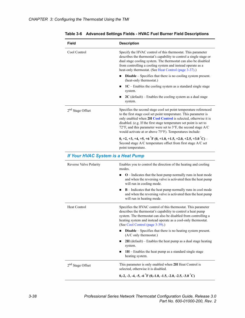
Beta Draft Confidential
3-38 Professional Series Network Thermostat Configuration Guide, Release 3.0Part No. 600-01000-200, Rev. 2
CHAPTER 3: Configuring the Thermostat Using the TMI
Cool Control Specify the HVAC control of this thermostat. This parameter describes the thermostat’s capability to control a single stage or dual stage cooling system. The thermostat can also be disabled from controlling a cooling system and instead operate as a heat-only thermostat. (See Heat Control (page 3-37).)
Disable – Specifies that there is no cooling system present. (heat-only thermostat.)
1C – Enables the cooling system as a standard single stage system.
2C (default) – Enables the cooling system as a dual stage system.
2nd Stage Offset Specifies the second stage cool set point temperature referenced to the first stage cool set point temperature. This parameter is only enabled when 2H Cool Control is selected, otherwise it is disabled. (e.g. If the first stage temperature set point is set to 72°F, and this parameter were set to 3°F, the second stage A/C would activate at or above 75°F). Temperatures include:
0, +2, +3, +4, +5, +6 °F (0, +1.0, +1.5, +2.0, +2.5, +3.0 °C) – Second stage A/C temperature offset from first stage A/C set point temperature.
If Your HVAC System is a Heat Pump
Reverse Valve Polarity Enables you to control the direction of the heating and cooling modes.
O – Indicates that the heat pump normally runs in heat mode and when the reversing valve is activated then the heat pump will run in cooling mode.
B – Indicates that the heat pump normally runs in cool mode and when the reversing valve is activated then the heat pump will run in heating mode.
Heat Control Specifies the HVAC control of this thermostat. This parameter describes the thermostat’s capability to control a heat pump system. The thermostat can also be disabled from controlling a heating system and instead operate as a cool-only thermostat. (See Cool Control (page 3-39).)
Disable – Specifies that there is no heating system present. (A/C only thermostat.)
2H (default) – Enables the heat pump as a dual stage heating system.
1H – Enables the heat pump as a standard single stage heating system.
2nd Stage Offset This parameter is only enabled when 2H Heat Control is selected, otherwise it is disabled.
0,-2, -3, -4, -5, -6 °F (0,-1.0, -1.5, -2.0, -2.5, -3.0 °C)
Table 3-6 Advanced Settings Fields - HVAC Fuel Burner Field Descriptions
Field Description
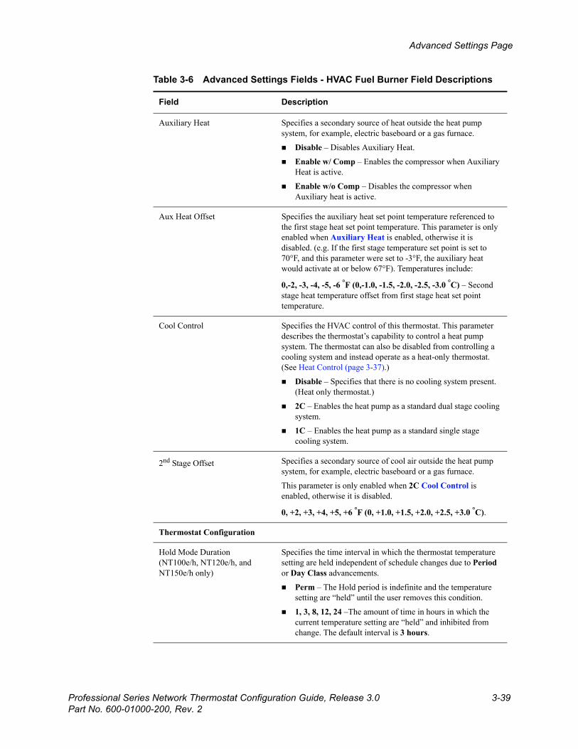
Beta Draft ConfidentialAdvanced Settings Page
Professional Series Network Thermostat Configuration Guide, Release 3.0 3-39Part No. 600-01000-200, Rev. 2
Auxiliary Heat Specifies a secondary source of heat outside the heat pump system, for example, electric baseboard or a gas furnace.
Disable – Disables Auxiliary Heat.
Enable w/ Comp – Enables the compressor when Auxiliary Heat is active.
Enable w/o Comp – Disables the compressor when Auxiliary heat is active.
Aux Heat Offset Specifies the auxiliary heat set point temperature referenced to the first stage heat set point temperature. This parameter is only enabled when Auxiliary Heat is enabled, otherwise it is disabled. (e.g. If the first stage temperature set point is set to 70°F, and this parameter were set to -3°F, the auxiliary heat would activate at or below 67°F). Temperatures include:
0,-2, -3, -4, -5, -6 °F (0,-1.0, -1.5, -2.0, -2.5, -3.0 °C) – Second stage heat temperature offset from first stage heat set point temperature.
Cool Control Specifies the HVAC control of this thermostat. This parameter describes the thermostat’s capability to control a heat pump system. The thermostat can also be disabled from controlling a cooling system and instead operate as a heat-only thermostat. (See Heat Control (page 3-37).)
Disable – Specifies that there is no cooling system present. (Heat only thermostat.)
2C – Enables the heat pump as a standard dual stage cooling system.
1C – Enables the heat pump as a standard single stage cooling system.
2nd Stage Offset Specifies a secondary source of cool air outside the heat pump system, for example, electric baseboard or a gas furnace.
This parameter is only enabled when 2C Cool Control is enabled, otherwise it is disabled.
0, +2, +3, +4, +5, +6 °F (0, +1.0, +1.5, +2.0, +2.5, +3.0 °C).
Thermostat Configuration
Hold Mode Duration (NT100e/h, NT120e/h, and NT150e/h only)
Specifies the time interval in which the thermostat temperature setting are held independent of schedule changes due to Period or Day Class advancements.
Perm – The Hold period is indefinite and the temperature setting are “held” until the user removes this condition.
1, 3, 8, 12, 24 –The amount of time in hours in which the current temperature setting are “held” and inhibited from change. The default interval is 3 hours.
Table 3-6 Advanced Settings Fields - HVAC Fuel Burner Field Descriptions
Field Description
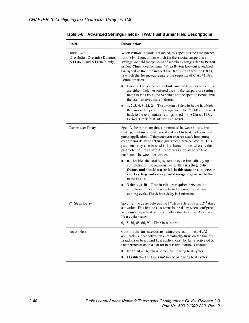
Beta Draft Confidential
3-40 Professional Series Network Thermostat Configuration Guide, Release 3.0Part No. 600-01000-200, Rev. 2
CHAPTER 3: Configuring the Thermostat Using the TMI
Hold/OBO(One Button Override) Duration(NT130e/h and NT160e/h only)
When Button Lockout is disabled, this specifies the time interval for the Hold function in which the thermostat temperature settings are held independent of schedule changes due to Period or Day Class advancements. When Button Lockout is enabled, this specifies the time interval for One Button Override (OBO) in which the thermostat temperature setpoints of Class #1 Day Period are used.
Perm – The period is indefinite and the temperature setting are either “held” or referred back to the temperature settings noted in the Day Class Schedule for the specific Period until the user removes this condition.
1, 2, 3, 4, 8, 12, 24 –The amount of time in hours in which the current temperature settings are either “held” or referred back to the temperature settings noted in the Class #1 Day Period. The default interval is 3 hours.
Compressor Delay Specify the minimum time (in minutes) between successive heating, cooling or heat to cool and cool to heat cycles in heat pump applications. This parameter ensures a safe heat pump compressor delay or off time guaranteed between cycles. This parameter may also be used in fuel burner mode, whereby this parameter ensures a safe A/C compressor delay or off time guaranteed between A/C cycles.
0 – Enables the cooling system to cycle immediately upon completion of the previous cycle. This is a diagnostic feature and should not be left in this state or compressor short cycling and subsequent damage may occur to the compressor.
3 through 10 – Time in minutes required between the completion of a cooling cycle and the next subsequent cooling cycle. The default delay is 3 minutes.
2nd Stage Delay Specifies the delay between the 1st stage activation and 2nd stage activation. This feature also controls the delay when configured as a single stage heat pump and when the start of an Auxiliary Heat cycle occurs.
0, 15, 30, 45, 60, 90 - Time in minutes
Fan on Heat Controls the fan state during heating cycles. In most HVAC applications, heat activation automatically turns on the fan, but in radiant or baseboard heat applications, the fan is activated by the thermostat upon a call for heat if this feature is enabled.
Enabled – The fan is forced ‘on’ during heat cycles.
Disabled – The fan is not forced on during heat cycles.
Table 3-6 Advanced Settings Fields - HVAC Fuel Burner Field Descriptions
Field Description
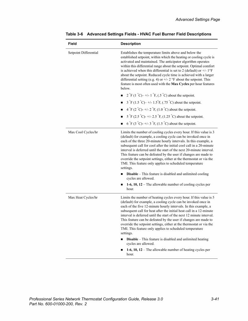
Beta Draft ConfidentialAdvanced Settings Page
Professional Series Network Thermostat Configuration Guide, Release 3.0 3-41Part No. 600-01000-200, Rev. 2
Setpoint Differential Establishes the temperature limits above and below the established setpoint, within which the heating or cooling cycle is activated and maintained. The anticipator algorithm operates within this differential range about the setpoint. Optimal comfort is achieved when this differential is set to 2 (default) or +/- 1°F about the setpoint. Reduced cycle time is achieved with a larger differential setting (e.g. 4) or +/- 2 °F about the setpoint. This feature is most often used with the Max Cycles per hour features below.
2 °F (1 °C)– +/- 1 °F, (.5 °C) about the setpoint.
3 °F (1.5 °C)– +/- 1.5°F, (.75 °C) about the setpoint.
4 °F (2 °C)- +/- 2 °F, (1.0 °C) about the setpoint.
5 °F (2.5 °C)- +/- 2.5 °F, (1.25 °C) about the setpoint.
6 °F (3 °C)- +/- 3 °F, (1.5 °C) about the setpoint.
Max Cool Cycles/hr Limits the number of cooling cycles every hour. If this value is 3 (default) for example, a cooling cycle can be invoked once in each of the three 20-minute hourly intervals. In this example, a subsequent call for cool after the initial cool call in a 20-minute interval is deferred until the start of the next 20-minute interval. This feature can be defeated by the user if changes are made to override the setpoint settings, either at the thermostat or via the TMI. This feature only applies to scheduled temperature settings.
Disable – This feature is disabled and unlimited cooling cycles are allowed.
1-6, 10, 12 – The allowable number of cooling cycles per hour.
Max Heat Cycles/hr Limits the number of heating cycles every hour. If this value is 5 (default) for example, a cooling cycle can be invoked once in each of the five 12-minute hourly intervals. In this example, a subsequent call for heat after the initial heat call in a 12-minute interval is deferred until the start of the next 12 minute interval. This feature can be defeated by the user if changes are made to override the setpoint settings, either at the thermostat or via the TMI. This feature only applies to scheduled temperature settings.
Disable – This feature is disabled and unlimited heating cycles are allowed.
1-6, 10, 12 – The allowable number of heating cycles per hour.
Table 3-6 Advanced Settings Fields - HVAC Fuel Burner Field Descriptions
Field Description
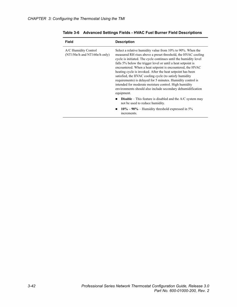
Beta Draft Confidential
3-42 Professional Series Network Thermostat Configuration Guide, Release 3.0Part No. 600-01000-200, Rev. 2
CHAPTER 3: Configuring the Thermostat Using the TMI
A/C Humidity Control (NT150e/h and NT160e/h only)
Select a relative humidity value from 10% to 90%. When the measured RH rises above a preset threshold, the HVAC cooling cycle is initiated. The cycle continues until the humidity level falls 5% below the trigger level or until a heat setpoint is encountered. When a heat setpoint is encountered, the HVAC heating cycle is invoked. After the heat setpoint has been satisfied, the HVAC cooling cycle (to satisfy humidity requirements) is delayed for 5 minutes. Humidity control is intended for moderate moisture control. High humidity environments should also include secondary dehumidification equipment.
Disable – This feature is disabled and the A/C system may not be used to reduce humidity.
10% – 90% – Humidity threshold expressed in 5% increments.
Table 3-6 Advanced Settings Fields - HVAC Fuel Burner Field Descriptions
Field Description
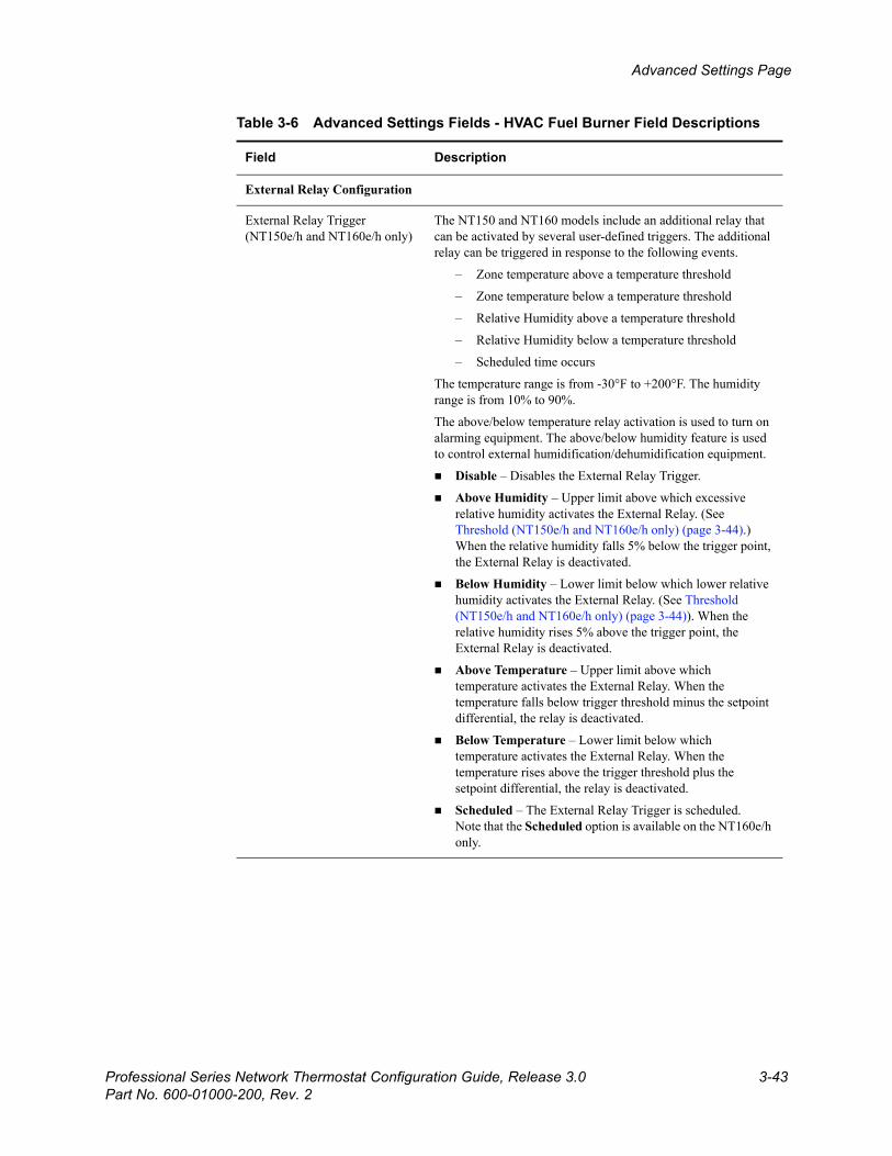
Beta Draft ConfidentialAdvanced Settings Page
Professional Series Network Thermostat Configuration Guide, Release 3.0 3-43Part No. 600-01000-200, Rev. 2
External Relay Configuration
External Relay Trigger (NT150e/h and NT160e/h only)
The NT150 and NT160 models include an additional relay that can be activated by several user-defined triggers. The additional relay can be triggered in response to the following events.
– Zone temperature above a temperature threshold
– Zone temperature below a temperature threshold
– Relative Humidity above a temperature threshold
– Relative Humidity below a temperature threshold
– Scheduled time occurs
The temperature range is from -30°F to +200°F. The humidity range is from 10% to 90%.
The above/below temperature relay activation is used to turn on alarming equipment. The above/below humidity feature is used to control external humidification/dehumidification equipment.
Disable – Disables the External Relay Trigger.
Above Humidity – Upper limit above which excessive relative humidity activates the External Relay. (See Threshold (NT150e/h and NT160e/h only) (page 3-44).) When the relative humidity falls 5% below the trigger point, the External Relay is deactivated.
Below Humidity – Lower limit below which lower relative humidity activates the External Relay. (See Threshold (NT150e/h and NT160e/h only) (page 3-44)). When the relative humidity rises 5% above the trigger point, the External Relay is deactivated.
Above Temperature – Upper limit above which temperature activates the External Relay. When the temperature falls below trigger threshold minus the setpoint differential, the relay is deactivated.
Below Temperature – Lower limit below which temperature activates the External Relay. When the temperature rises above the trigger threshold plus the setpoint differential, the relay is deactivated.
Scheduled – The External Relay Trigger is scheduled.Note that the Scheduled option is available on the NT160e/h only.
Table 3-6 Advanced Settings Fields - HVAC Fuel Burner Field Descriptions
Field Description
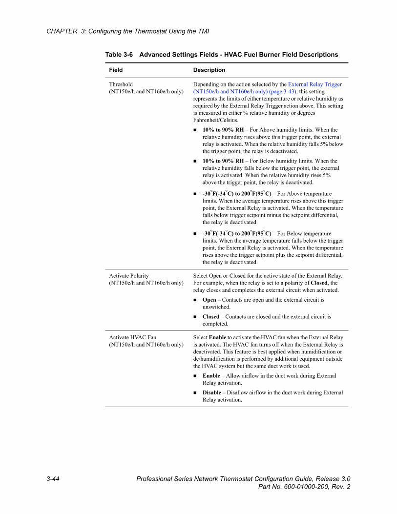
Beta Draft Confidential
3-44 Professional Series Network Thermostat Configuration Guide, Release 3.0Part No. 600-01000-200, Rev. 2
CHAPTER 3: Configuring the Thermostat Using the TMI
Threshold(NT150e/h and NT160e/h only)
Depending on the action selected by the External Relay Trigger (NT150e/h and NT160e/h only) (page 3-43), this setting represents the limits of either temperature or relative humidity as required by the External Relay Trigger action above. This setting is measured in either % relative humidity or degrees Fahrenheit/Celsius.
10% to 90% RH – For Above humidity limits. When the relative humidity rises above this trigger point, the external relay is activated. When the relative humidity falls 5% below the trigger point, the relay is deactivated.
10% to 90% RH – For Below humidity limits. When the relative humidity falls below the trigger point, the external relay is activated. When the relative humidity rises 5% above the trigger point, the relay is deactivated.
-30°F(-34°C) to 200°F(95°C) – For Above temperature limits. When the average temperature rises above this trigger point, the External Relay is activated. When the temperature falls below trigger setpoint minus the setpoint differential, the relay is deactivated.
-30°F(-34°C) to 200°F(95°C) – For Below temperature limits. When the average temperature falls below the trigger point, the External Relay is activated. When the temperature rises above the trigger setpoint plus the setpoint differential, the relay is deactivated.
Activate Polarity(NT150e/h and NT160e/h only)
Select Open or Closed for the active state of the External Relay. For example, when the relay is set to a polarity of Closed, the relay closes and completes the external circuit when activated.
Open – Contacts are open and the external circuit is unswitched.
Closed – Contacts are closed and the external circuit is completed.
Activate HVAC Fan(NT150e/h and NT160e/h only)
Select Enable to activate the HVAC fan when the External Relay is activated. The HVAC fan turns off when the External Relay is deactivated. This feature is best applied when humidification or de/humidification is performed by additional equipment outside the HVAC system but the same duct work is used.
Enable – Allow airflow in the duct work during External Relay activation.
Disable – Disallow airflow in the duct work during External Relay activation.
Table 3-6 Advanced Settings Fields - HVAC Fuel Burner Field Descriptions
Field Description

Beta Draft ConfidentialAdvanced Settings Page
Professional Series Network Thermostat Configuration Guide, Release 3.0 3-45Part No. 600-01000-200, Rev. 2
Reset on Submit Consult a Proliphix support representative prior to changing this setting. Performs a software reset on the thermostat. All current settings are maintained after the execution of this reset. This reset is performed to return the thermostat to a known state after abnormal behavior.
No Action (default) – A software reset is NOT performed after clicking Submit.
Software Reset – Invokes a software reset after clicking Submit.
Table 3-6 Advanced Settings Fields - HVAC Fuel Burner Field Descriptions
Field Description
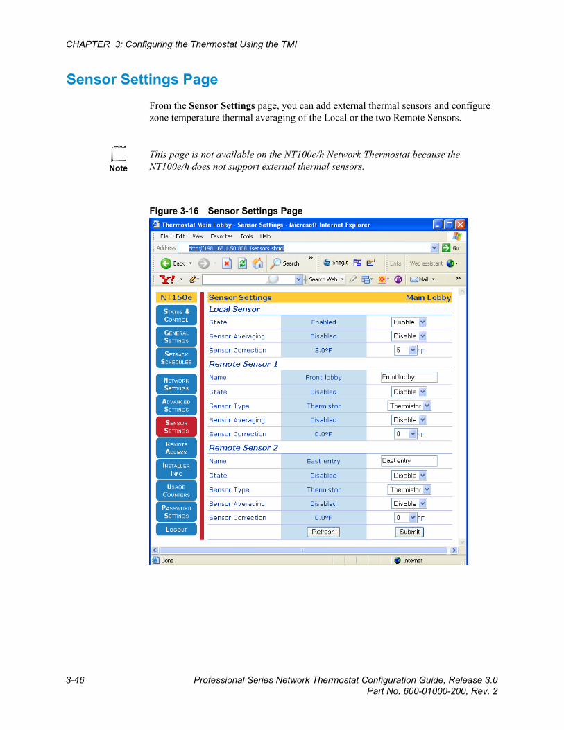
Beta Draft Confidential
3-46 Professional Series Network Thermostat Configuration Guide, Release 3.0Part No. 600-01000-200, Rev. 2
CHAPTER 3: Configuring the Thermostat Using the TMI
Sensor Settings PageFrom the Sensor Settings page, you can add external thermal sensors and configure zone temperature thermal averaging of the Local or the two Remote Sensors.
Figure 3-16 Sensor Settings Page
NoteThis page is not available on the NT100e/h Network Thermostat because the NT100e/h does not support external thermal sensors.
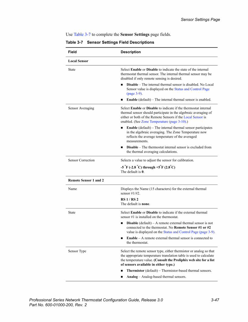
Beta Draft ConfidentialSensor Settings Page
Professional Series Network Thermostat Configuration Guide, Release 3.0 3-47Part No. 600-01000-200, Rev. 2
Use Table 3-7 to complete the Sensor Settings page fields.
Table 3-7 Sensor Settings Field Descriptions
Field Description
Local Sensor
State Select Enable or Disable to indicate the state of the internal thermostat thermal sensor. The internal thermal sensor may be disabled if only remote sensing is desired.
Disable – The internal thermal sensor is disabled. No Local Sensor value is displayed on the Status and Control Page (page 3-9).
Enable (default) – The internal thermal sensor is enabled.
Sensor Averaging Select Enable or Disable to indicate if the thermostat internal thermal sensor should participate in the algebraic averaging of either or both of the Remote Sensors if the Local Sensor is enabled. (See Zone Temperature (page 3-10).)
Enable (default) – The internal thermal sensor participates in the algebraic averaging. The Zone Temperature now reflects the average temperature of the averaged measurements.
Disable – The thermostat internal sensor is excluded from the thermal averaging calculations.
Sensor Correction Selects a value to adjust the sensor for calibration.
-5 °F (-2.8 °C) through +5°F (2.8°C)The default is 0.
Remote Sensor 1 and 2
Name Displays the Name (15 characters) for the external thermal sensor #1/#2.
RS 1 / RS 2The default is none.
State Select Enable or Disable to indicate if the external thermal sensor #1 is installed on the thermostat.
Disable (default) – A remote external thermal sensor is not connected to the thermostat. No Remote Sensor #1 or #2 value is displayed on the Status and Control Page (page 3-9).
Enable – A remote external thermal sensor is connected to the thermostat.
Sensor Type Select the remote sensor type, either thermistor or analog so that the appropriate temperature translation table is used to calculate the temperature value. (Consult the Proliphix web site for a list of sensors available in either type.)
Thermistor (default) – Thermistor-based thermal sensors.
Analog – Analog-based thermal sensors.
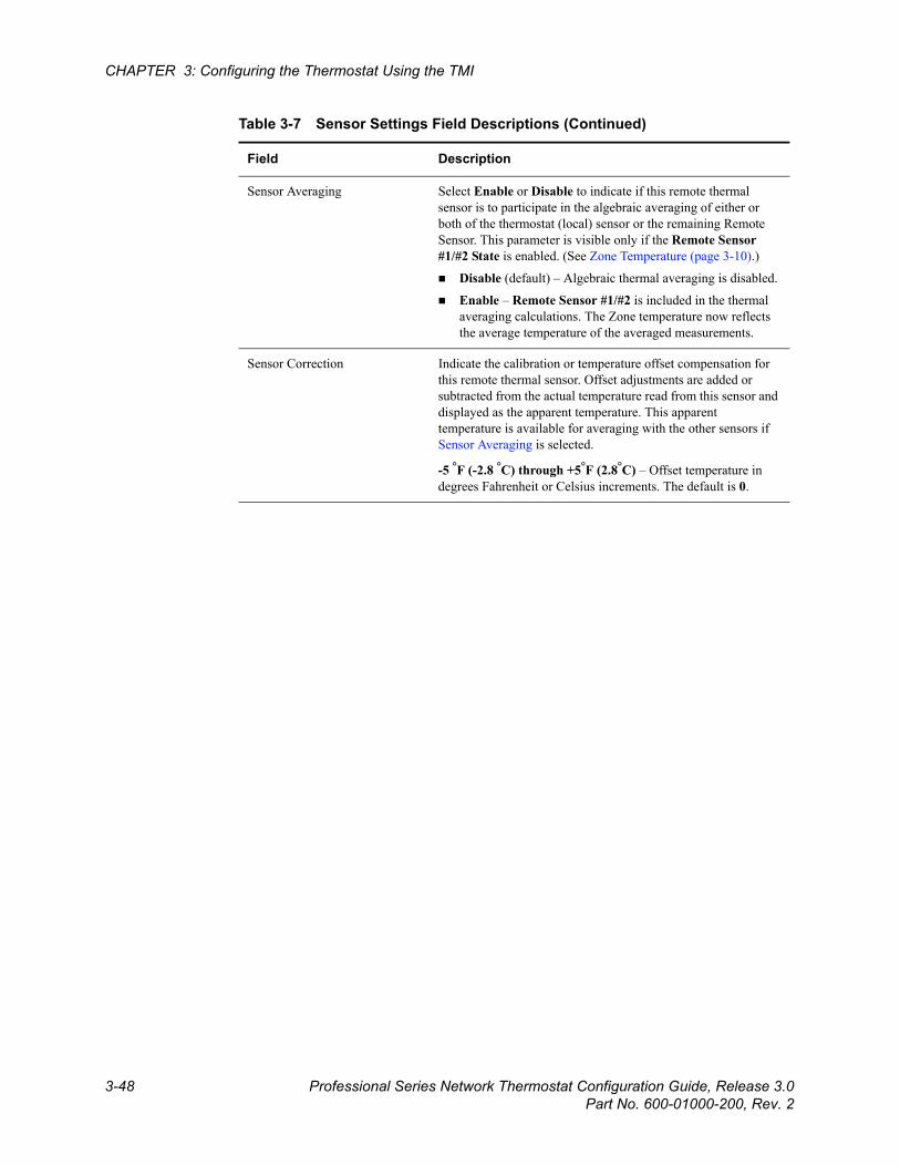
Beta Draft Confidential
3-48 Professional Series Network Thermostat Configuration Guide, Release 3.0Part No. 600-01000-200, Rev. 2
CHAPTER 3: Configuring the Thermostat Using the TMI
Sensor Averaging Select Enable or Disable to indicate if this remote thermal sensor is to participate in the algebraic averaging of either or both of the thermostat (local) sensor or the remaining Remote Sensor. This parameter is visible only if the Remote Sensor #1/#2 State is enabled. (See Zone Temperature (page 3-10).)
Disable (default) – Algebraic thermal averaging is disabled.
Enable – Remote Sensor #1/#2 is included in the thermal averaging calculations. The Zone temperature now reflects the average temperature of the averaged measurements.
Sensor Correction Indicate the calibration or temperature offset compensation for this remote thermal sensor. Offset adjustments are added or subtracted from the actual temperature read from this sensor and displayed as the apparent temperature. This apparent temperature is available for averaging with the other sensors if Sensor Averaging is selected.
-5 °F (-2.8 °C) through +5°F (2.8°C) – Offset temperature in degrees Fahrenheit or Celsius increments. The default is 0.
Table 3-7 Sensor Settings Field Descriptions (Continued)
Field Description
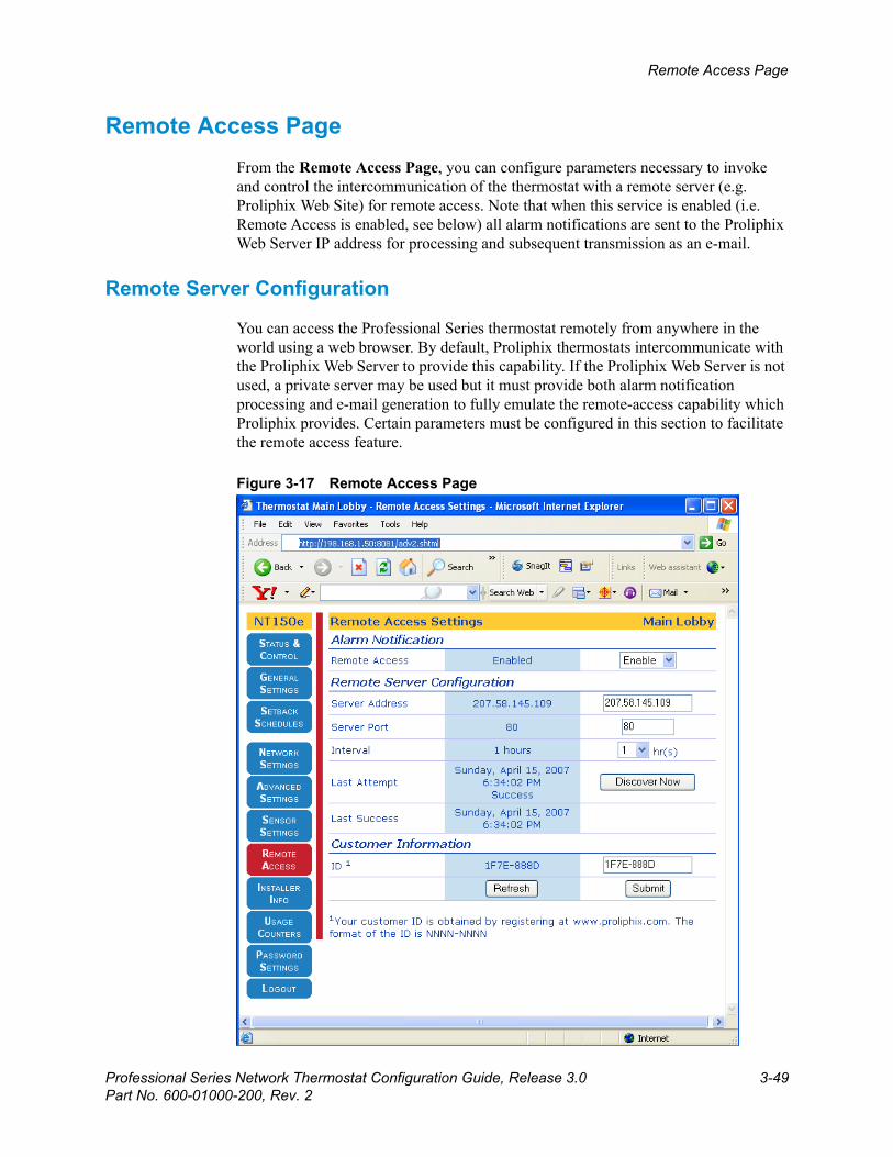
Beta Draft ConfidentialRemote Access Page
Professional Series Network Thermostat Configuration Guide, Release 3.0 3-49Part No. 600-01000-200, Rev. 2
Remote Access Page From the Remote Access Page, you can configure parameters necessary to invoke and control the intercommunication of the thermostat with a remote server (e.g. Proliphix Web Site) for remote access. Note that when this service is enabled (i.e. Remote Access is enabled, see below) all alarm notifications are sent to the Proliphix Web Server IP address for processing and subsequent transmission as an e-mail.
Remote Server Configuration
You can access the Professional Series thermostat remotely from anywhere in the world using a web browser. By default, Proliphix thermostats intercommunicate with the Proliphix Web Server to provide this capability. If the Proliphix Web Server is not used, a private server may be used but it must provide both alarm notification processing and e-mail generation to fully emulate the remote-access capability which Proliphix provides. Certain parameters must be configured in this section to facilitate the remote access feature.
Figure 3-17 Remote Access Page
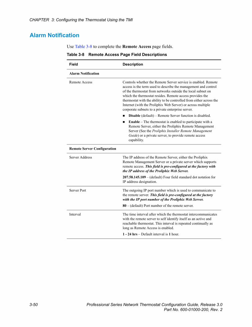
Beta Draft Confidential
3-50 Professional Series Network Thermostat Configuration Guide, Release 3.0Part No. 600-01000-200, Rev. 2
CHAPTER 3: Configuring the Thermostat Using the TMI
Alarm Notification
Use Table 3-8 to complete the Remote Access page fields.
Table 3-8 Remote Access Page Field Descriptions
Field Description
Alarm Notification
Remote Access Controls whether the Remote Server service is enabled. Remote access is the term used to describe the management and control of the thermostat from networks outside the local subnet on which the thermostat resides. Remote access provides the thermostat with the ability to be controlled from either across the Internet (with the Proliphix Web Server) or across multiple corporate subnets to a private enterprise server.
Disable (default) – Remote Server function is disabled.
Enable – The thermostat is enabled to participate with a Remote Server, either the Proliphix Remote Management Server (See the Proliphix Installer Remote Management Guide) or a private server, to provide remote access capability.
Remote Server Configuration
Server Address The IP address of the Remote Server, either the Proliphix Remote Management Server or a private server which supports remote access. This field is pre-configured at the factory with the IP address of the Proliphix Web Server.
207.58.145.109 – (default) Four field standard dot notation for IP address designation.
Server Port The outgoing IP port number which is used to communicate to the remote server. This field is pre-configured at the factory with the IP port number of the Proliphix Web Server.
80 – (default) Port number of the remote server.
Interval The time interval after which the thermostat intercommunicates with the remote server to self identify itself as an active and reachable thermostat. This interval is repeated continually as long as Remote Access is enabled.
1 - 24 hrs – Default interval is 1 hour.
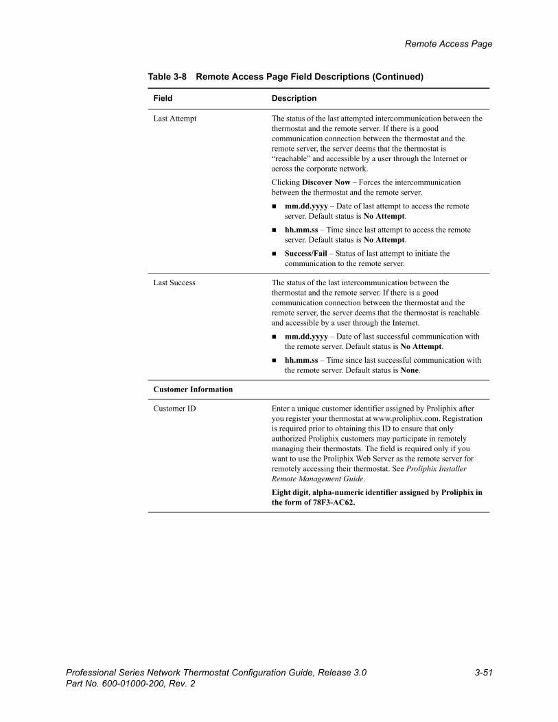
Beta Draft ConfidentialRemote Access Page
Professional Series Network Thermostat Configuration Guide, Release 3.0 3-51Part No. 600-01000-200, Rev. 2
Last Attempt The status of the last attempted intercommunication between the thermostat and the remote server. If there is a good communication connection between the thermostat and the remote server, the server deems that the thermostat is “reachable” and accessible by a user through the Internet or across the corporate network.
Clicking Discover Now – Forces the intercommunication between the thermostat and the remote server.
mm.dd.yyyy – Date of last attempt to access the remote server. Default status is No Attempt.
hh.mm.ss – Time since last attempt to access the remote server. Default status is No Attempt.
Success/Fail – Status of last attempt to initiate the communication to the remote server.
Last Success The status of the last intercommunication between the thermostat and the remote server. If there is a good communication connection between the thermostat and the remote server, the server deems that the thermostat is reachable and accessible by a user through the Internet.
mm.dd.yyyy – Date of last successful communication with the remote server. Default status is No Attempt.
hh.mm.ss – Time since last successful communication with the remote server. Default status is None.
Customer Information
Customer ID Enter a unique customer identifier assigned by Proliphix after you register your thermostat at www.proliphix.com. Registration is required prior to obtaining this ID to ensure that only authorized Proliphix customers may participate in remotely managing their thermostats. The field is required only if you want to use the Proliphix Web Server as the remote server for remotely accessing their thermostat. See Proliphix Installer Remote Management Guide.
Eight digit, alpha-numeric identifier assigned by Proliphix in the form of 78F3-AC62.
Table 3-8 Remote Access Page Field Descriptions (Continued)
Field Description
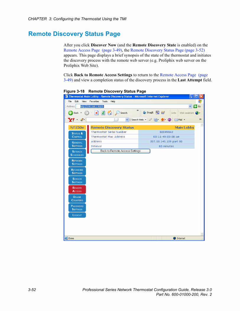
Beta Draft Confidential
3-52 Professional Series Network Thermostat Configuration Guide, Release 3.0Part No. 600-01000-200, Rev. 2
CHAPTER 3: Configuring the Thermostat Using the TMI
Remote Discovery Status PageAfter you click Discover Now (and the Remote Discovery State is enabled) on the Remote Access Page (page 3-49), the Remote Discovery Status Page (page 3-52) appears. This page displays a brief synopsis of the state of the thermostat and initiates the discovery process with the remote web server (e.g. Proliphix web server on the Proliphix Web Site).
Click Back to Remote Access Settings to return to the Remote Access Page (page 3-49) and view a completion status of the discovery process in the Last Attempt field.
Figure 3-18 Remote Discovery Status Page
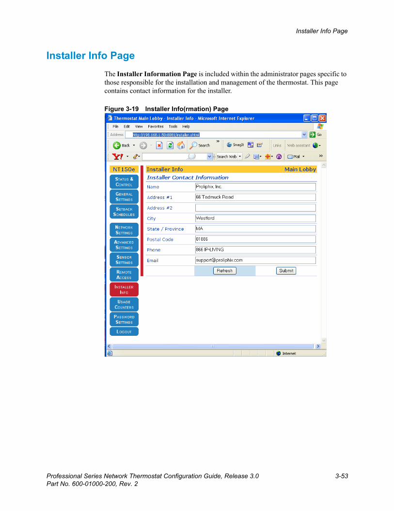
Beta Draft ConfidentialInstaller Info Page
Professional Series Network Thermostat Configuration Guide, Release 3.0 3-53Part No. 600-01000-200, Rev. 2
Installer Info Page The Installer Information Page is included within the administrator pages specific to those responsible for the installation and management of the thermostat. This page contains contact information for the installer.
Figure 3-19 Installer Info(rmation) Page
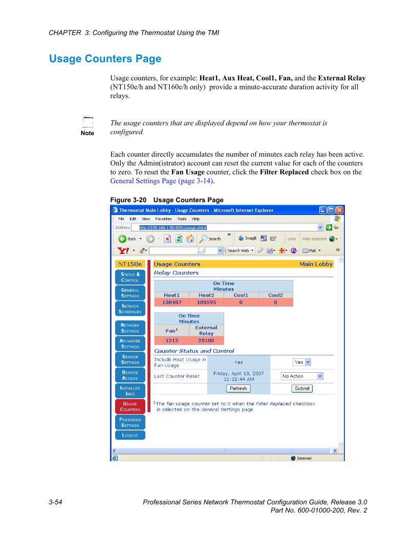
Beta Draft Confidential
3-54 Professional Series Network Thermostat Configuration Guide, Release 3.0Part No. 600-01000-200, Rev. 2
CHAPTER 3: Configuring the Thermostat Using the TMI
Usage Counters PageUsage counters, for example: Heat1, Aux Heat, Cool1, Fan, and the External Relay (NT150e/h and NT160e/h only) provide a minute-accurate duration activity for all relays.
Each counter directly accumulates the number of minutes each relay has been active. Only the Admin(istrator) account can reset the current value for each of the counters to zero. To reset the Fan Usage counter, click the Filter Replaced check box on the General Settings Page (page 3-14).
Figure 3-20 Usage Counters Page
NoteThe usage counters that are displayed depend on how your thermostat is configured.
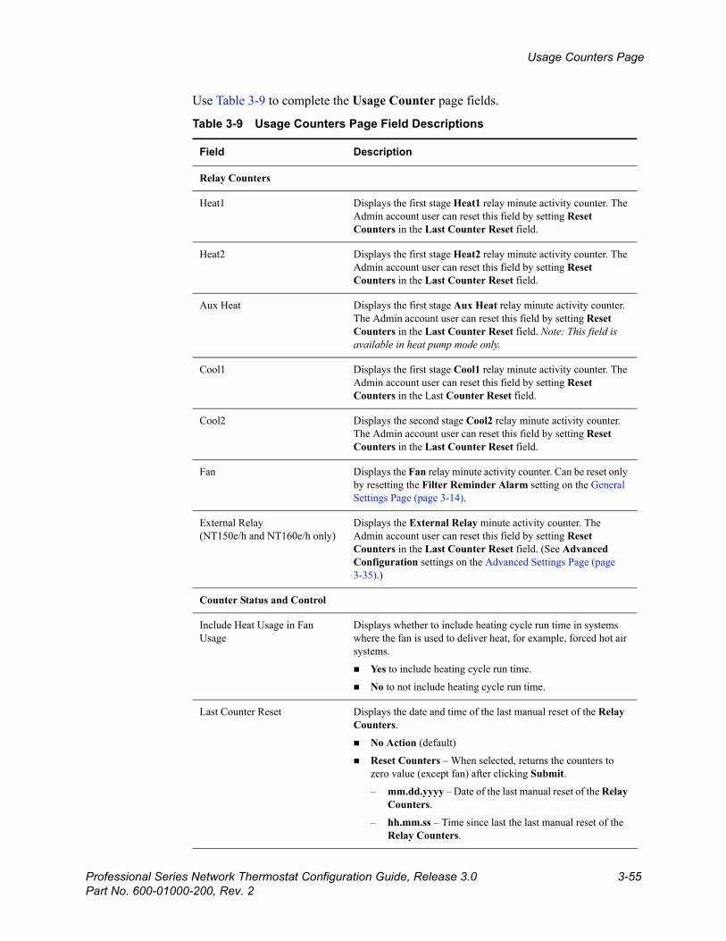
Beta Draft ConfidentialUsage Counters Page
Professional Series Network Thermostat Configuration Guide, Release 3.0 3-55Part No. 600-01000-200, Rev. 2
Use Table 3-9 to complete the Usage Counter page fields.
Table 3-9 Usage Counters Page Field Descriptions
Field Description
Relay Counters
Heat1 Displays the first stage Heat1 relay minute activity counter. The Admin account user can reset this field by setting Reset Counters in the Last Counter Reset field.
Heat2 Displays the first stage Heat2 relay minute activity counter. The Admin account user can reset this field by setting Reset Counters in the Last Counter Reset field.
Aux Heat Displays the first stage Aux Heat relay minute activity counter. The Admin account user can reset this field by setting Reset Counters in the Last Counter Reset field. Note: This field is available in heat pump mode only.
Cool1 Displays the first stage Cool1 relay minute activity counter. The Admin account user can reset this field by setting Reset Counters in the Last Counter Reset field.
Cool2 Displays the second stage Cool2 relay minute activity counter. The Admin account user can reset this field by setting Reset Counters in the Last Counter Reset field.
Fan Displays the Fan relay minute activity counter. Can be reset only by resetting the Filter Reminder Alarm setting on the General Settings Page (page 3-14).
External Relay(NT150e/h and NT160e/h only)
Displays the External Relay minute activity counter. The Admin account user can reset this field by setting Reset Counters in the Last Counter Reset field. (See Advanced Configuration settings on the Advanced Settings Page (page 3-35).)
Counter Status and Control
Include Heat Usage in Fan Usage
Displays whether to include heating cycle run time in systems where the fan is used to deliver heat, for example, forced hot air systems.
Yes to include heating cycle run time.
No to not include heating cycle run time.
Last Counter Reset Displays the date and time of the last manual reset of the Relay Counters.
No Action (default)
Reset Counters – When selected, returns the counters to zero value (except fan) after clicking Submit.
– mm.dd.yyyy – Date of the last manual reset of the Relay Counters.
– hh.mm.ss – Time since last the last manual reset of the Relay Counters.

Beta Draft Confidential
3-56 Professional Series Network Thermostat Configuration Guide, Release 3.0Part No. 600-01000-200, Rev. 2
CHAPTER 3: Configuring the Thermostat Using the TMI
Password Settings PageYou can access additional installer-specific pages after successfully logging in as an administrator. As a user, you may change your password. As an administrator, you may also change the administrator and/or user passwords.
Figure 3-21 Admin Password Settings Page

Beta Draft ConfidentialPassword Settings Page
Professional Series Network Thermostat Configuration Guide, Release 3.0 3-57Part No. 600-01000-200, Rev. 2
Use Table 3-10 to complete the Password Settings page fields.
The Administrator can access all installer-specific pages. The User account is limited to viewing and controlling the following pages:
Status & Control Page (page 3-9)
General Settings Page (page 3-14)
Setback Schedules Page (page 3-19)
Table 3-10 Admin Password Settings Field Descriptions
Field Description
Admin Password
New Password Enter an alpha-numeric password for the Administrator (admin) account. The password is case sensitive and limited to 15 alpha-numeric characters. The default password is admin.
Confirm Password Re-enter your password (from the New Password field).
User Password
New Password Enter an alpha-numeric password for the User account. The password is case sensitive and limited to 15 alpha-numeric characters. The default password is admin.
Confirm Password Re-enter your password (from the New Password field).

Beta Draft Confidential
3-58 Professional Series Network Thermostat Configuration Guide, Release 3.0Part No. 600-01000-200, Rev. 2
CHAPTER 3: Configuring the Thermostat Using the TMI
The User account can also change the user password as shown in Figure 3-22.
Figure 3-22 User Password Settings Page
Use Table 3-11 to complete the Admin Settings (User Password) page fields.
Table 3-11 Admin Settings (User Password) Field Descriptions
Field Description
User Password
New Password Enter an alpha-numeric password for the User account. The password is case sensitive and limited to 15 alpha-numeric characters. The default password is admin.
Confirm Password Re-enter your password (from the New Password field).

Chapter
Professional Series Network Thermostat Configuration Guide, Release 3.0 4-1Part No. 600-01000-200, Rev. 2
Beta Draft Confidential
4
TroubleshootingThis chapter describes how to reset the Proliphix thermostat.
Resetting the ThermostatAlthough it is highly unlikely that the thermostats are unable to perform correctly against unsolicited and unwanted network activity, occasionally a reset may be necessary to bring the thermostat back into proper operation.
Software Reset
A software reset reboots the network processor and retains the programming and thermostat setback schedules.
To perform a software reset at the thermostat:
1 From the Status & Control Screen (page 2-10), select Thermostat Control Screen (page 2-11).
2 Press and hold Reset for longer than 3 seconds (see Figure 2-9 on page 2-11).
Caution
Do not perform a software reset or factory reset on the thermostat until instructed to do so by a qualified Proliphix customer support representative. See Technical Support on page xv.
Beta Draft Confidential
4-2 Professional Series Network Thermostat Configuration Guide, Release 3.0Part No. 600-01000-200, Rev. 2
CHAPTER 4: Troubleshooting
Factory Reset
A factory reset clears the thermostat’s internal memory and returns the thermostat to the factory-default state.
To perform a factory reset at the thermostat:
1 Remove the thermostat cover from the base which is attached to the wall. (See the Proliphix Thermostat Installation Guide.)
2 Attach the top of the cover to the top of the base as a hinge.
3 Press and hold the middle button of thermostat while closing the cover into the base. Do not release the button until the LCD characters appear.
Caution
Performing a factory reset clears the setback scheduling and other programmed parameters. These settings can not be recovered after a reset. In addition, the IP addressing mode reverts back to DHCP, the current IP address is lost, and the thermostat becomes unreachable (until the thermostat retrieves a new address from the local DHCP server).
Beta Draft Confidential
Professional Series Network Thermostat Configuration Guide, Release 3.0 Index-1Part No. 600-01000-200, Rev. 2
Index
A
Advanced settings page 3-35Alarm
indication 2-4notification 3-50status 3-12
Alarm notification 3-50Alarm status screen
described 2-14
B
Button lockout 2-4
C
Calendar view 3-21Configuring the thermostat 1-2
using the TDI 2-1using the TMI 3-1
Cool setpoint temperature 2-5
D
Day class 3-20Default host name 3-3Default weekly schedule 3-21, 3-24Device name (zone name) 3-3DHCP. See Dynamic Host Configuration Protocol 3-2Down arrow 2-2Dynamic Host Configuration Protocol 3-2
E
External thermal sensorssettings 3-47
F
Factory reset 4-2Filter
set change reminder 3-17Firewall settings 3-32Fuel burner
settings for 3-37
G
Gateway address 3-31General settings page 3-14
H
Heat pumpsettings for 3-38
Heat setpoint temperature 2-5HTML interface 3-5HVAC screen
described 2-6HVAC state 3-11
Index-2 Professional Series Network Thermostat Configuration Guide, Release 3.0Part No. 600-01000-200, Rev. 2
Index
I
Installer info page 3-53Installer information screen
described 2-16IP Address 3-3
L
LCD screen on thermostat 2-1Left button 2-2Logging in to the thermostat (remotely) 1-3, 3-4Login page 3-7
M
MAC address 3-31middle button 2-2
N
Network connectivity 2-4Network mask 3-33Network status screen
described 2-15
O
Occupied day classdescribed 3-20settings 3-22
Other day classdescribed 3-20settings 3-22
P
Passwordchanging 3-58setting 3-57
Period state 2-5Primary screen 2-3
R
Real time clock 1-3Relative humidity 3-10, 3-12Remote access page 3-49Remote discovery status page 3-52Remote management 3-4Remote sensor
current temperature 3-10Right button 2-2
S
Secondary screen 2-3Security 3-32Sensor settings page 3-46Sensor status screen
described 2-9Setback schedules page 3-29Software reset 4-1Special days 3-25Status & control page 3-7, 3-9Status & control screen
described 2-10Subnet mask 3-31
T
TDI. See Thermostat Device Interface 1-2Temperature hold 2-5Thermostat
accessing the initial HTML page 3-5buttons and screen options 2-1configuring using TDI 2-1configuring using TMI 3-1connecting to local network 3-3default screen described 2-4logging in 1-3, 3-4managing remotely 3-4primary screen 2-3resetting 4-1scheduling 3-20secondary screen 2-3
Thermostat control screendescribed 2-11
Thermostat Device Interface 1-2, 2-1Thermostat Management Interface 1-2, 3-5Thermostat status screen
described 2-13Time 2-5TMI. See Thermostat Management Interface 1-2Troubleshooting 4-1
Beta Draft ConfidentialIndex
Professional Series Network Thermostat Configuration Guide, Release 3.0 Index-3Part No. 600-01000-200, Rev. 2
U
Unoccupied day classdescribed 3-20settings 3-22
Up arrow 2-2Usage counters 3-54
V
VPN 3-4
W
Web port identifier 3-3

Index-4 Professional Series Network Thermostat Configuration Guide, Release 3.0Part No. 600-01000-200, Rev. 2
Index