Embed Size (px)
Citation preview
BestCap® Ultra-low ESRHigh Power Pulse Supercapacitors
070820-A

IMPORTANT INFORMATION/DISCLAIMER
All product specifications, statements, information and data (collectively, the “Information”) in this datasheet or made available on the website are subject to change. The customer is responsible for checking and verifying the extent to which the Information contained in this publication is applicable to an order at the time the order is placed. All Information given herein is believed to be accurate and reliable, but it is presented without guarantee, warranty, or responsibility of any kind, expressed or implied.
Statements of suitability for certain applications are based on AVX’s knowledge of typical operating conditions for such applications, but are not intended to constitute and AVX specifically disclaims any warranty concerning suitability for a specific customer application or use.
ANY USE OF PRODUCT OUTSIDE OF SPECIFICATIONS OR ANY STORAGE OR INSTALLATION INCONSISTENT WITH PRODUCT GUIDANCE VOIDS ANY WARRANTY.
The Information is intended for use only by customers who have the requisite experience and capability to determine the correct products for their application. Any technical advice inferred from this Information or otherwise provided by AVX with reference to the use of AVX’s products is given without regard, and AVX assumes no obligation or liability for the advice given or results obtained.
Although AVX designs and manufactures its products to the most stringent quality and safety standards, given the current state of the art, isolated component failures may still occur. Accordingly, customer applications which require a high degree of reliability or safety should employ suitable designs or other safeguards (such as installation of protective circuitry or redundancies) in order to ensure that the failure of an electrical component does not result in a risk of personal injury or property damage.
Unless specifically agreed to in writing, AVX has not tested or certified its products, services or deliverables for use in high risk applications including medical life support, medical device, direct physical patient contact, water treatment, nuclear facilities, weapon systems, mass and air transportation control, flammable environments, or any other potentially life critical uses. Customer understands and agrees that AVX makes no assurances that the products, services or deliverables are suitable for any high-risk uses. Under no circumstances does AVX warrant or guarantee suitability for any customer design or manufacturing process.
Although all product–related warnings, cautions and notes must be observed, the customer should not assume that all safety measures are indicted or that other measures may not be required.
121119
– bestcap® ultra-low esr high power pulse supercapacitors –
The Important Information/Disclaimer is incorporated in the catalog where these specifications came from or available online at www.avx.com/disclaimer/ by reference and should be reviewed in full before placing any order.
INTRODUCTION TO BESTCAP® .........................................................................................................................................................................................1
BESTCAP® GENERAL INFORMATION ...............................................................................................................................................................................2
SECTION 1Electrical Ratings (A-B Series) ...............................................................................................................................................................................................4
Electrical Ratings (BZ01/02/05/09) .......................................................................................................................................................................................5
SECTION 2Mechanical Specifications (A-Lead) ......................................................................................................................................................................................8
Mechanical Specifications (W-Lead) .....................................................................................................................................................................................9
Mechanical Specifications (H-Lead) ....................................................................................................................................................................................10
Mechanical Specifications (L-Lead).....................................................................................................................................................................................11
Mechanical Specifications (N-Lead) ....................................................................................................................................................................................12
Mechanical Specifications (S-Lead) ....................................................................................................................................................................................13
Packaging Specifications/Quantities (BZ01/02/05/09) .......................................................................................................................................................14
Cleaning/Handling/Storage Conditions/Part Marking/Termination Finish ..........................................................................................................................15
Product Safety Materials Handling/Materials and Weight/Typical Weight Data .................................................................................................................16
SECTION 3Electrical Characteristics – Schematic, Typical Characteristics .........................................................................................................................................18
Mounting Procedure on a PCB for BestCap® .......................................................................................................................................................................19
Qualification Test Summary .................................................................................................................................................................................................20
SECTION 4Application Notes/BestCap® Construction/Voltage Drop ....................................................................................................................................................22
Enhancing the Power Capability of Primary Batteries .........................................................................................................................................................24
BestCap® for GSM/GPRS PCMCIA Modems ........................................................................................................................................................................25
SECTION 5Extended Temperature Range ..............................................................................................................................................................................................27
BestCap® Ultra-low ESR High Power Pulse SupercapacitorsTable of Contents
– bestcap® ultra-low esr high power pulse supercapacitors –
The Important Information/Disclaimer is incorporated in the catalog where these specifications came from or available online at www.avx.com/disclaimer/ by reference and should be reviewed in full before placing any order.
1
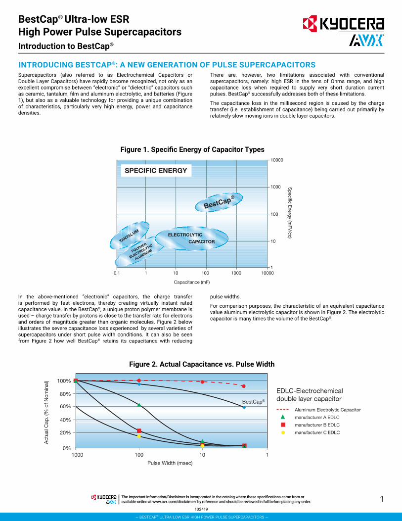
INTRODUCING BESTCAP®: A NEW GENERATION OF PULSE SUPERCAPACITORSSupercapacitors (also referred to as Electrochemical Capacitors or Double Layer Capacitors) have rapidly become recognized, not only as an excellent compromise between “electronic” or “dielectric” capacitors such as ceramic, tantalum, film and aluminum electrolytic, and batteries (Figure 1), but also as a valuable technology for providing a unique combination of characteristics, particularly very high energy, power and capacitance densities.
There are, however, two limitations associated with conventional supercapacitors, namely: high ESR in the tens of Ohms range, and high capacitance loss when required to supply very short duration current pulses. BestCap® successfully addresses both of these limitations.
The capacitance loss in the millisecond region is caused by the charge transfer (i.e. establishment of capacitance) being carried out primarily by relatively slow moving ions in double layer capacitors.
In the above-mentioned “electronic” capacitors, the charge transfer is performed by fast electrons, thereby creating virtually instant rated capacitance value. In the BestCap®, a unique proton polymer membrane is used – charge transfer by protons is close to the transfer rate for electrons and orders of magnitude greater than organic molecules. Figure 2 below illustrates the severe capacitance loss experienced by several varieties of supercapacitors under short pulse width conditions. It can also be seen from Figure 2 how well BestCap® retains its capacitance with reducing
pulse widths.
For comparison purposes, the characteristic of an equivalent capacitance value aluminum electrolytic capacitor is shown in Figure 2. The electrolytic capacitor is many times the volume of the BestCap®.
Figure 1. Specific Energy of Capacitor Types
ELECTROLYTIC
CAPACITOR
POLYMER
ELECTROLYTIC
ALUMINUM
TANTALUM
100
10
11000100101 000011.0
1000
10000
SPECIFIC ENERGY
Capacitance (mF)
Sp
eci�c Energy (m
FV/cc)
®
0%
20%
40%
60%
80%
100%
1000 100
Act
ual C
ap. (
% o
f Nom
inal
)
Pulse Width (msec)
101
EDLC-Electrochemicaldouble layer capacitor
Aluminum Electrolytic Capacitor
manufacturer A EDLC
manufacturer B EDLC
manufacturer C EDLC
®
Figure 2. Actual Capacitance vs. Pulse Width
BestCap® Ultra-low ESR High Power Pulse SupercapacitorsIntroduction to BestCap®
102419
– bestcap® ultra-low esr high power pulse supercapacitors –
The Important Information/Disclaimer is incorporated in the catalog where these specifications came from or available online at www.avx.com/disclaimer/ by reference and should be reviewed in full before placing any order.
2
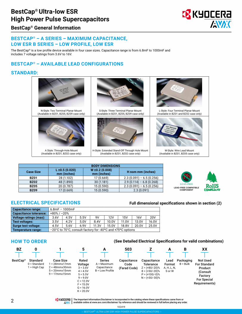
BESTCAP® – A SERIES – MAXIMUM CAPACITANCE, LOW ESR B SERIES – LOW PROFILE, LOW ESRThe BestCap® is a low profile device available in four case sizes. Capacitance range is from 6.8mF to 1000mF and includes 7 voltage ratings from 3.6V to 16V.
BESTCAP® – AVAILABLE LEAD CONFIGURATIONS
STANDARD:
N-Style: Two Terminal Planar Mount (Available in BZ01, BZ05, BZ09 case only)
S-Style: Three Terminal Planar Mount (Available in BZ01, BZ05, BZ09 case only)
L-Style: Four Terminal Planar Mount (Available in BZ01 and BZ02 case only)
A Style: Through-Hole Mount (Available in BZ01, BZ02 case only)
H-Style: Extended Stand-Off Through Hole Mount (Available in BZ01, BZ02 case only)
W-Style: Wire Lead Mount (Available in BZ01, BZ05 case only)
BODY DIMENSIONS
Case Size L ±0.5 (0.020) mm (inches)
W ±0.2 (0.008) mm (inches) H nom mm (inches)
BZ01 28 (1.102) 17 (0.669) 2.3 (0.091) – 6.5 (0.256)BZ02 48 (1.890) 30 (1.181) 2.9 (0.114) – 6.8 (0.268)BZ05 20 (0.787) 15 (0.590) 2.3 (0.091) – 6.5 (0.256)BZ09 17 (0.669) 15 (0.590) 2.3 (0.091)
LEAD-FREE COMPATIBLECOMPONENT
ELECTRICAL SPECIFICATIONS Full dimensional specifications shown in section (2)
(See Detailed Electrical Specifications for valid combinations)
Capacitance range: 6.8mF – 1000mFCapacitance tolerance: +80% / –20%Voltage ratings (max): 3.6V 4.5V 5.5V 9V 12V 15V 16V 20VTest voltages: 3.5V 4.2V 5.0V 8.4V 10.0V 11.0V 13.0V 16.0VSurge test voltage: 4.5V 5.6V 6.9V 11.3V 15.0V 18.8V 20.0V 25.0VTemperature range: –20°C to 70°C, consult factory for -40ºC and +75ºC options
HOW TO ORDERBZ 0 1 5 A 503 Z A B XX
BestCap® Standard0 = Standard1 = High Cap
Rated Voltage3 = 3.6V4 = 4.5V5 = 5.5V 9 = 9.0V
C = 12.0V F = 15.0V G = 16.0V K = 20.0V
Case Size1 = 28mmx17mm2 = 48mmx30mm5 = 20mmx15mm9 = 17mmx15mm
SeriesA = Maximum Capacitance
B = Low Profile
Capacitance Tolerance
Z = (+80/-20)% 8 = (+50/-20)% P = (+100/-0)% N = (+30/-30)%
Lead Format
A, H, L, N, S or W
PackagingB = Bulk
Not Used For Standard
Product (Consult Factory
For Special Requirements)
Capacitance Code
(Farad Code)
BestCap® Ultra-low ESR High Power Pulse SupercapacitorsBestCap® General Information
102419
– bestcap® ultra-low esr high power pulse supercapacitors –
The Important Information/Disclaimer is incorporated in the catalog where these specifications came from or available online at www.avx.com/disclaimer/ by reference and should be reviewed in full before placing any order.
3
SECTION 1Electrical Ratings
– bestcap® ultra-low esr high power pulse supercapacitors –
The Important Information/Disclaimer is incorporated in the catalog where these specifications came from or available online at www.avx.com/disclaimer/ by reference and should be reviewed in full before placing any order.
4
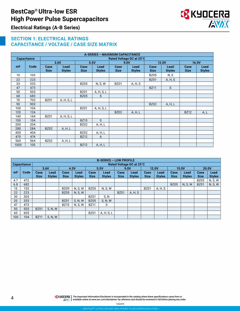
SECTION 1: ELECTRICAL RATINGSCAPACITANCE / VOLTAGE / CASE SIZE MATRIX
A-SERIES – MAXIMUM CAPACITANCECapacitance Rated Voltage DC at 25°C
mF Code3.6V 5.5V 9.0V 12.0V 16.0V
Case Size
Lead Styles
Case Size
Lead Styles
Case Size
Lead Styles
Case Size
Lead Styles
Case Size
Lead Styles
10 103 BZ05 N, S22 223 BZ01 A, H, S33 333 BZ05 N, S, W BZ01 A, H, S47 473 BZ11 S50 503 BZ01 A, H, S, L68 683 BZ05 S70 703 BZ01 A, H, S, L90 903 BZ02 A, H, L
100 104 BZ01 A, H, S, L120 124 BZ02 A, H, L BZ12 A, L140 144 BZ01 A, H, S, L150 154 BZ15 S200 204 BZ02 A, H, L280 284 BZ02 A, H, L400 404 BZ02 A, H, L470 474 BZ12 A560 564 BZ02 A, H, L
1000 105 BZ12 A, H, L
BestCap® Ultra-low ESR High Power Pulse SupercapacitorsElectrical Ratings (A-B Series)
102419
B-SERIES – LOW PROFILECapacitance Rated Voltage DC at 25°C
mF Code3.6V 4.5V 5.5V 9.0V 12.0V 15.0V 20.0V
Case Size
Lead Styles
Case Size
Lead Styles
Case Size
Lead Styles
Case Size
Lead Styles
Case Size
Lead Styles
Case Size
Lead Styles
Case Size
Lead Styles
4.7 472 BZ05 N, S, W6.8 682 BZ05 N, S, W BZ01 N, S, W15 153 BZ09 N, S, W BZ05 N, S, W BZ01 A, H, S22 223 BZ05 N, S, W BZ01 A, H, S30 303 BZ01 S, N33 333 BZ01 S, N, W BZ05 S, N, W47 473 BZ15 N, S, W BZ11 S50 503 BZ01 S, N, W60 603 BZ01 A, H, S, L
100 104 BZ11 S, N, W
– bestcap® ultra-low esr high power pulse supercapacitors –
The Important Information/Disclaimer is incorporated in the catalog where these specifications came from or available online at www.avx.com/disclaimer/ by reference and should be reviewed in full before placing any order.
5
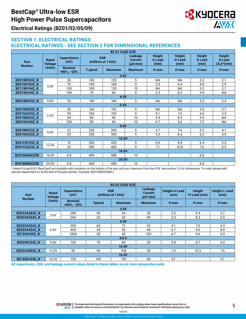
SECTION 1: ELECTRICAL RATINGSELECTRICAL RATINGS - SEE SECTION 2 FOR DIMENSIONAL REFERENCES
BZ 01 CASE SIZE
Part Number
Rated Voltage (Volts)
Capacitance (mF)
ESR (mOhms at 1 kHz)
Leakage Current
(µA max)
Height A-Lead (mm)
Height H-Lead (mm)
Height S-Lead (mm)
Height S-Lead
(AJ)*(mm)Nominal
+80%, –20% T ypical Maximum Maximum H max H max H max H max
3.6VBZ013B503Z_B
3.6V
50 100 120 5 NA NA 3.2 2.1BZ013A703Z_B 70 140 168 5 3.5 6.4 4.0 2.9BZ113B104Z_B 100 100 120 10 NA NA 3.2 2.1BZ013A144Z_B 140 70 84 5 5.3 8.2 5.8 NA
4.5VBZ014B333Z_B 4.5V 33 150 180 5 NA NA 3.5 2.4
5.5VBZ015B303Z_B
5.5V
30 160 192 5 NA NA 3.8 2.7BZ015A503Z_B 50 160 192 5 4.1 7.0 4.6 3.5BZ015B603Z_B 60 80 96 10 5.4 8.3 5.9 NABZ015A104Z_B 100 80 96 10 6.7 9.6 7.2 NA
9.0VBZ019B223Z_B 9.0V 22 250 300 5 4.7 7.6 5.2 4.1BZ019A333Z_B 33 250 300 5 5.5 8.4 6.0 4.9
12.0VBZ01CB153Z_B 12.0V 15 350 420 5 5.9 8.8 6.4 5.3BZ01CA223Z_B 22 350 420 5 7.1 10.0 7.6 6.5
16.0VBZ01GB682ZSB 16.0V 6.8 400 480 10 6.8
20.0VBZ01KB682ZSB 20.0V 6.8 400 480 10 6.8
* Select S-Lead BZ01 BestCap® are available with insulation on the bottom of the part and zero clearance from the PCB. See section 2.6 for dimensions. To order, please add special requirement AJ to the end of the part number. Example: BZ013B503ZSBAJ
BZ 02 CASE SIZE
Part Number
Rated Voltage (Volts)
Capacitance (mF)
ESR (mOhms at 1 kHz)
Leakage Current
(µA max)
Height A-Lead (mm)
Height H-Lead (mm)
Height L-Lead (mm)
Nominal +80%, –20% Typical Maximum Maximum H max H max H max
3.6VBZ023A284Z_B 3.6V 280 45 54 20 3.5 6.4 3.7BZ023A564Z_B 560 25 30 40 5.3 8.2 5.5
5.5VBZ025A204Z_B
5.5V200 60 72 20 4.1 7.0 4.3
BZ025A404Z_B 400 35 42 40 6.7 9.6 6.9BZ125A105Z_B 1000 35 42 120 6.7 9.6 6.9
9.0 VBZ029A124Z_B 9.0V 120 70 84 20 5.8 8.7 6.0
12.0VBZ02CA903Z_B 12.0V 90 90 108 20 7.4 10.3 7.6
16.0VBZ12GA124Z_B 16.0V 120 160 192 60 9.1 9.1
All capacitance, ESR, and leakage current values listed in these tables are at room temperature only.
BestCap® Ultra-low ESR High Power Pulse SupercapacitorsElectrical Ratings (BZ01/02/05/09)
102419
– bestcap® ultra-low esr high power pulse supercapacitors –
The Important Information/Disclaimer is incorporated in the catalog where these specifications came from or available online at www.avx.com/disclaimer/ by reference and should be reviewed in full before placing any order.

6
BZ 05 CASE SIZE
Part Number
Rated Voltage (Volts)
Capacitance (mF)
ESR (mOhms at 1 kHz)
Leakage Current
(µA max)
Height N-Lead (mm)
Height S-Lead (mm)
Nominal +80%, –20% Typical Maximum Maximum H max H max
4.5VBZ054B223Z_B 4.5V 22 170 204 5 2.3 2.3BZ154B473Z_B 47 170 204 10 2.3 2.3
5.5VBZ055B153Z_B
5.5V
15 250 300 5 2.7 2.7BZ055A333Z_B 33 250 300 5 3.5 3.5BZ055B333Z_B 33 125 150 10 NA 4.8BZ155A104Z_B 100 125 150 20 NA 6.1
12.0VBZ05CA103Z_B 12.0V 10 500 600 55 6.5 6.5
15.0VBZ05FB682Z_B 15.0V 6.8 500 600 10 5.8 5.8
20.0VBZ05KB472ZSB 20.0V 4.7 700 840 10 6.7
BestCap® Ultra-low ESR High Power Pulse SupercapacitorsElectrical Ratings (BZ01/02/05/09)
102419
BZ 09 CASE SIZE
Part Number
Rated Voltage (Volts)
Capacitance (mF)
ESR (mOhms at 1 kHz)
Leakage Current
(µA max)
Height N-Lead (mm)
Height S-Lead (mm)
Nominal +80%, –20% Typical Maximum Maximum H max H max
4.5VBZ094B153Z_BAI 4.5V 15 250 300 5 2.4* 2.3*
* The 4.5V BZ09 BestCap® are available only in a special low profile version.All capacitance, ESR, and leakage current values listed in these tables are at room temperature only.
– bestcap® ultra-low esr high power pulse supercapacitors –
The Important Information/Disclaimer is incorporated in the catalog where these specifications came from or available online at www.avx.com/disclaimer/ by reference and should be reviewed in full before placing any order.

7
SECTION 2Mechanical Specifications
– bestcap® ultra-low esr high power pulse supercapacitors –
The Important Information/Disclaimer is incorporated in the catalog where these specifications came from or available online at www.avx.com/disclaimer/ by reference and should be reviewed in full before placing any order.
8
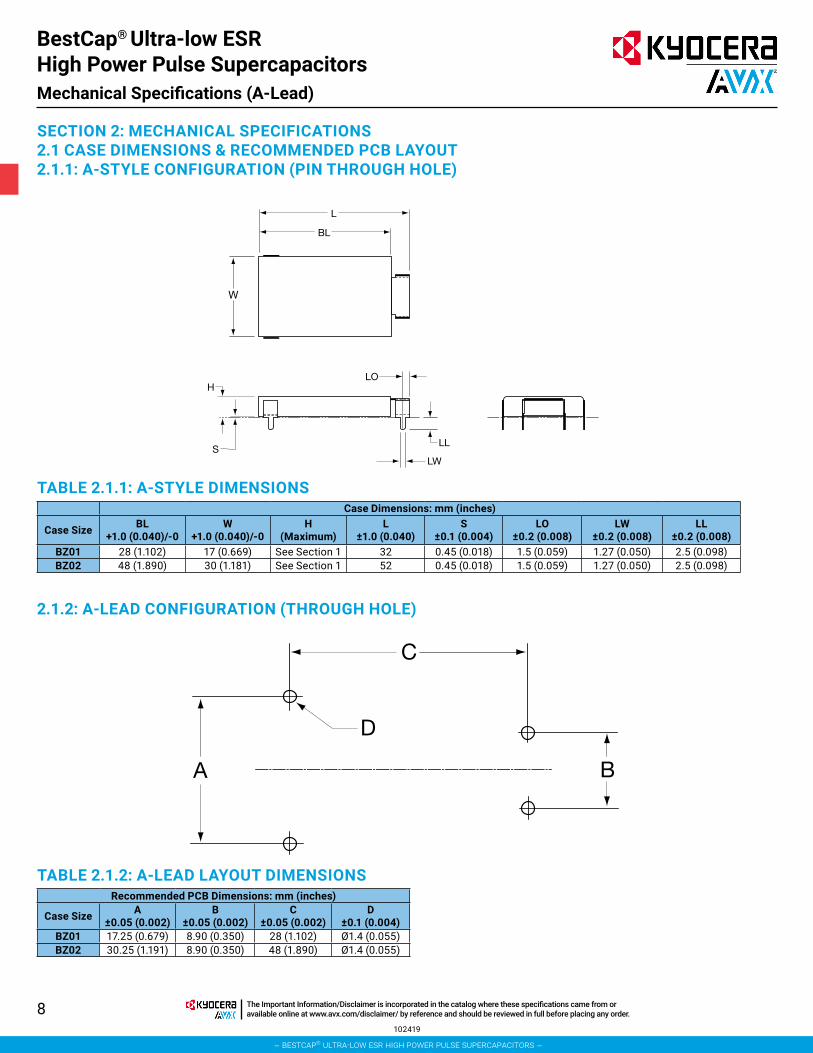
SECTION 2: MECHANICAL SPECIFICATIONS2.1 CASE DIMENSIONS & RECOMMENDED PCB LAYOUT2.1.1: A-STYLE CONFIGURATION (PIN THROUGH HOLE)
L
BL
S
W
H
LW
LL
LO
C
B
D
A
2.1.2: A-LEAD CONFIGURATION (THROUGH HOLE)
TABLE 2.1.1: A-STYLE DIMENSIONSCase Dimensions: mm (inches)
Case Size BL +1.0 (0.040)/-0
W +1.0 (0.040)/-0
H (Maximum)
L ±1.0 (0.040)
S ±0.1 (0.004)
LO ±0.2 (0.008)
LW ±0.2 (0.008)
LL ±0.2 (0.008)
BZ01 28 (1.102) 17 (0.669) See Section 1 32 0.45 (0.018) 1.5 (0.059) 1.27 (0.050) 2.5 (0.098)BZ02 48 (1.890) 30 (1.181) See Section 1 52 0.45 (0.018) 1.5 (0.059) 1.27 (0.050) 2.5 (0.098)
TABLE 2.1.2: A-LEAD LAYOUT DIMENSIONSRecommended PCB Dimensions: mm (inches)
Case Size A ±0.05 (0.002)
B ±0.05 (0.002)
C ±0.05 (0.002)
D ±0.1 (0.004)
BZ01 17.25 (0.679) 8.90 (0.350) 28 (1.102) Ø1.4 (0.055)BZ02 30.25 (1.191) 8.90 (0.350) 48 (1.890) Ø1.4 (0.055)
BestCap® Ultra-low ESR High Power Pulse SupercapacitorsMechanical Specifications (A-Lead)
102419
– bestcap® ultra-low esr high power pulse supercapacitors –
The Important Information/Disclaimer is incorporated in the catalog where these specifications came from or available online at www.avx.com/disclaimer/ by reference and should be reviewed in full before placing any order.
9
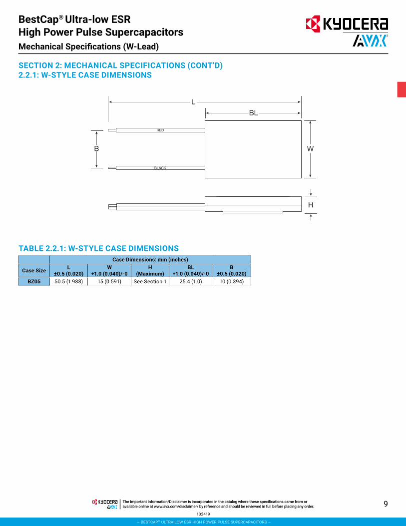
SECTION 2: MECHANICAL SPECIFICATIONS (CONT’D)2.2.1: W-STYLE CASE DIMENSIONS
TABLE 2.2.1: W-STYLE CASE DIMENSIONSCase Dimensions: mm (inches)
Case Size L ±0.5 (0.020)
W +1.0 (0.040)/-0
H (Maximum)
BL +1.0 (0.040)/-0
B ±0.5 (0.020)
BZ05 50.5 (1.988) 15 (0.591) See Section 1 25.4 (1.0) 10 (0.394)
W
H
B
BL
L
RED
BLACK
BestCap® Ultra-low ESR High Power Pulse SupercapacitorsMechanical Specifications (W-Lead)
102419
– bestcap® ultra-low esr high power pulse supercapacitors –
The Important Information/Disclaimer is incorporated in the catalog where these specifications came from or available online at www.avx.com/disclaimer/ by reference and should be reviewed in full before placing any order.
10
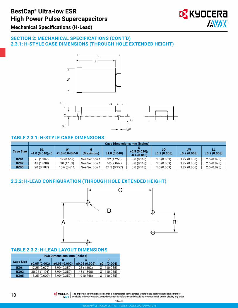
SECTION 2: MECHANICAL SPECIFICATIONS (CONT’D)2.3.1: H-STYLE CASE DIMENSIONS (THROUGH HOLE EXTENDED HEIGHT)
2.3.2: H-LEAD CONFIGURATION (THROUGH HOLE EXTENDED HEIGHT)
TABLE 2.3.1: H-STYLE CASE DIMENSIONSCase Dimensions: mm (inches)
Case Size BL +1.0 (0.040)/-0
W +1.0 (0.040)/-0
H (Maximum)
L ±1.0 (0.040)
S +0.5 (0.020)/ -0.4 (0.016)
LO ±0.2 (0.008)
LW ±0.2 (0.008)
LL ±0.2 (0.008)
BZ01 28 (1.102) 17 (0.669) See Section 1 32 (1.260) 3.0 (0.118) 1.5 (0.059) 1.27 (0.050) 2.5 (0.098)BZ02 48 (1.890) 30 (1.181) See Section 1 52 (2.047) 3.0 (0.118) 1.5 (0.059) 1.27 (0.050) 2.5 (0.098)BZ05 20 (0.787) 15.6 (0.614) See Section 1 24.3 (0.957) 3.0 (0.118) 1.5 (0.059) 1.27 (0.050) 2.5 (0.098)
TABLE 2.3.2: H-LEAD LAYOUT DIMENSIONSPCB Dimensions: mm (inches)
Case Size A ±0.05 (0.002)
B ±0.05 (0.002)
C ±0.05 (0.002)
D ±0.1 (0.004)
BZ01 17.25 (0.679) 8.90 (0.350) 28 (1.102) Ø1.4 (0.055)BZ02 30.25 (1.191) 8.90 (0.350) 48 (1.890) Ø1.4 (0.055)BZ05 15.25 (0.600) 8.90 (0.350) 19 (0.748) Ø1.4 (0.055)
L
BL
S
W
H
LW
LL
LO
C
B
D
A
BestCap® Ultra-low ESR High Power Pulse SupercapacitorsMechanical Specifications (H-Lead)
102419
– bestcap® ultra-low esr high power pulse supercapacitors –
The Important Information/Disclaimer is incorporated in the catalog where these specifications came from or available online at www.avx.com/disclaimer/ by reference and should be reviewed in full before placing any order.

11
SECTION 2: MECHANICAL SPECIFICATIONS (CONT’D)2.4.1: L-LEAD CONFIGURATION (PLANAR MOUNT)
2.4.2: L-LEAD CONFIGURATION (PLANAR MOUNT)
TABLE 2.4.1: L-STYLE CASE DIMENSIONSCase Dimensions: mm (inches)
Case Size BL +1.0 (0.040)/-0
W +1.0 (0.040)/-0
H (Maximum)
L ±1.0 (0.040)
S ±0.2 (0.008)
LO ±0.2 (0.008)
LW ±0.2 (0.008)
LL ±0.5 (0.020)
BZ01 28 (1.102) 17 (0.6691) See Section 1 33 0.55 (0.022) 1.5 (0.059) 1.27 (0.050) 2.4 (0.098)BZ02 48 (1.890) 30 (1.181) See Section 1 52 0.55 (0.022) 1.5 (0.059) 1.27 (0.050) 2.4 (0.098)
TABLE 2.4.2: L-STYLE LEAD LAYOUTPCB Dimensions: mm (inches)
Case Size A ±0.1 (0.004)
B ±0.1 (0.004)
C ±0.1 (0.004)
PL ±0.2 (0.008)
PW ±0.2 (0.008)
BZ01 19.2 (0.776) 10.8 (0.425) 28 (1.102) 3.0 (0.118) 3.7 (0.146)BZ02 32.2 (1.268) 10.8 (0.425) 48 (1.890) 3.2 (0.126) 3.7 (0.146)
L
BL
S
W
H
LO
LL LW
C
BA
PWPL
BestCap® Ultra-low ESR High Power Pulse SupercapacitorsMechanical Specifications (L-Lead)
102419
– bestcap® ultra-low esr high power pulse supercapacitors –
The Important Information/Disclaimer is incorporated in the catalog where these specifications came from or available online at www.avx.com/disclaimer/ by reference and should be reviewed in full before placing any order.
12
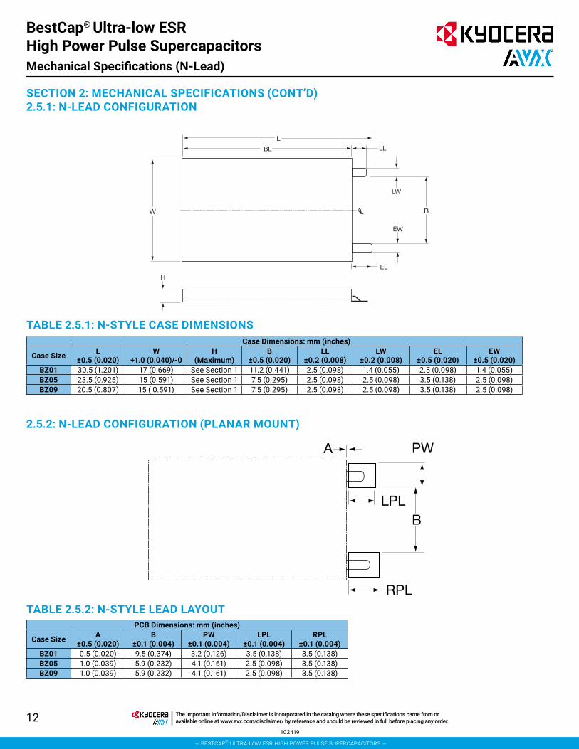
SECTION 2: MECHANICAL SPECIFICATIONS (CONT’D)2.5.1: N-LEAD CONFIGURATION
TABLE 2.5.1: N-STYLE CASE DIMENSIONS
TABLE 2.5.2: N-STYLE LEAD LAYOUT
2.5.2: N-LEAD CONFIGURATION (PLANAR MOUNT)
Case Dimensions: mm (inches)
Case Size L ±0.5 (0.020)
W +1.0 (0.040)/-0
H (Maximum)
B ±0.5 (0.020)
LL ±0.2 (0.008)
LW ±0.2 (0.008)
EL ±0.5 (0.020)
EW ±0.5 (0.020)
BZ01 30.5 (1.201) 17 (0.669) See Section 1 11.2 (0.441) 2.5 (0.098) 1.4 (0.055) 2.5 (0.098) 1.4 (0.055)BZ05 23.5 (0.925) 15 (0.591) See Section 1 7.5 (0.295) 2.5 (0.098) 2.5 (0.098) 3.5 (0.138) 2.5 (0.098)BZ09 20.5 (0.807) 15 ( 0.591) See Section 1 7.5 (0.295) 2.5 (0.098) 2.5 (0.098) 3.5 (0.138) 2.5 (0.098)
PCB Dimensions: mm (inches)
Case Size A ±0.5 (0.020)
B ±0.1 (0.004)
PW ±0.1 (0.004)
LPL ±0.1 (0.004)
RPL ±0.1 (0.004)
BZ01 0.5 (0.020) 9.5 (0.374) 3.2 (0.126) 3.5 (0.138) 3.5 (0.138)BZ05 1.0 (0.039) 5.9 (0.232) 4.1 (0.161) 2.5 (0.098) 3.5 (0.138)BZ09 1.0 (0.039) 5.9 (0.232) 4.1 (0.161) 2.5 (0.098) 3.5 (0.138)
L
LL
LC
LW
BL
W
EW
EL
B
H
A PW
BLPL
RPL
BestCap® Ultra-low ESR High Power Pulse SupercapacitorsMechanical Specifications (N-Lead)
102419
– bestcap® ultra-low esr high power pulse supercapacitors –
The Important Information/Disclaimer is incorporated in the catalog where these specifications came from or available online at www.avx.com/disclaimer/ by reference and should be reviewed in full before placing any order.
13
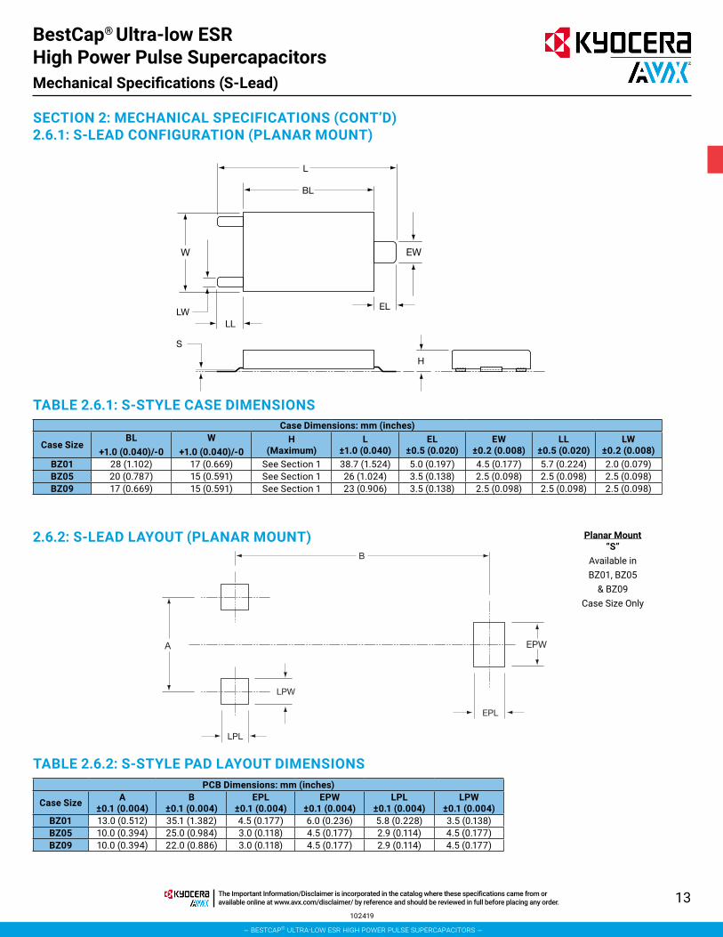
SECTION 2: MECHANICAL SPECIFICATIONS (CONT’D)2.6.1: S-LEAD CONFIGURATION (PLANAR MOUNT)
TABLE 2.6.1: S-STYLE CASE DIMENSIONS
TABLE 2.6.2: S-STYLE PAD LAYOUT DIMENSIONS
2.6.2: S-LEAD LAYOUT (PLANAR MOUNT)
Case Dimensions: mm (inches)
Case SizeBL
+1.0 (0.040)/-0W
+1.0 (0.040)/-0H
(Maximum)L
±1.0 (0.040)EL
±0.5 (0.020)EW
±0.2 (0.008)LL
±0.5 (0.020)LW
±0.2 (0.008)BZ01 28 (1.102) 17 (0.669) See Section 1 38.7 (1.524) 5.0 (0.197) 4.5 (0.177) 5.7 (0.224) 2.0 (0.079)BZ05 20 (0.787) 15 (0.591) See Section 1 26 (1.024) 3.5 (0.138) 2.5 (0.098) 2.5 (0.098) 2.5 (0.098)BZ09 17 (0.669) 15 (0.591) See Section 1 23 (0.906) 3.5 (0.138) 2.5 (0.098) 2.5 (0.098) 2.5 (0.098)
PCB Dimensions: mm (inches)
Case Size A ±0.1 (0.004)
B ±0.1 (0.004)
EPL ±0.1 (0.004)
EPW ±0.1 (0.004)
LPL ±0.1 (0.004)
LPW ±0.1 (0.004)
BZ01 13.0 (0.512) 35.1 (1.382) 4.5 (0.177) 6.0 (0.236) 5.8 (0.228) 3.5 (0.138)BZ05 10.0 (0.394) 25.0 (0.984) 3.0 (0.118) 4.5 (0.177) 2.9 (0.114) 4.5 (0.177)BZ09 10.0 (0.394) 22.0 (0.886) 3.0 (0.118) 4.5 (0.177) 2.9 (0.114) 4.5 (0.177)
L
BL
W EW
S
EL
LL
H
LW
B
LPL
LPW
A EPW
EPL
Planar Mount “S”
Available in BZ01, BZ05
& BZ09 Case Size Only
BestCap® Ultra-low ESR High Power Pulse SupercapacitorsMechanical Specifications (S-Lead)
102419
– bestcap® ultra-low esr high power pulse supercapacitors –
The Important Information/Disclaimer is incorporated in the catalog where these specifications came from or available online at www.avx.com/disclaimer/ by reference and should be reviewed in full before placing any order.
14
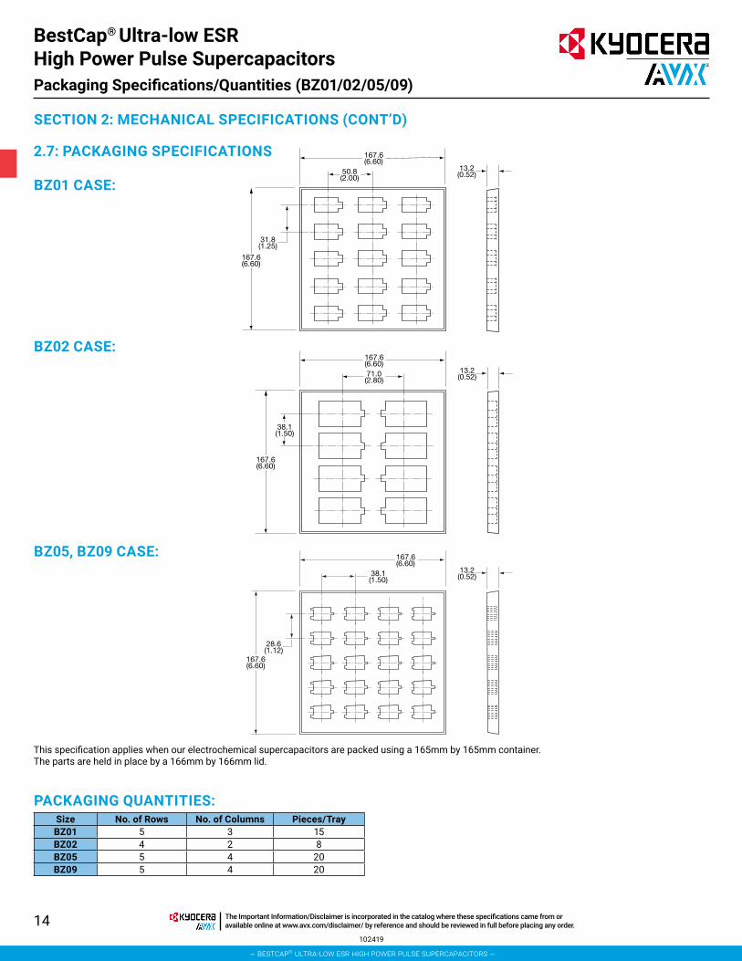
SECTION 2: MECHANICAL SPECIFICATIONS (CONT’D)
2.7: PACKAGING SPECIFICATIONS
BZ01 CASE:
BZ02 CASE:
BZ05, BZ09 CASE:
This specification applies when our electrochemical supercapacitors are packed using a 165mm by 165mm container. The parts are held in place by a 166mm by 166mm lid.
PACKAGING QUANTITIES:Size No. of Rows No. of Columns Pieces/TrayBZ01 5 3 15BZ02 4 2 8BZ05 5 4 20BZ09 5 4 20
167.6(6.60)
13.2(0.52)50.8
(2.00)
31.8(1.25)
167.6(6.60)
167.6(6.60)
13.2(0.52)71.0
(2.80)
38.1(1.50)
167.6(6.60)
167.6(6.60)
13.2(0.52)38.1
(1.50)
28.6(1.12)
167.6(6.60)
BestCap® Ultra-low ESR High Power Pulse SupercapacitorsPackaging Specifications/Quantities (BZ01/02/05/09)
102419
– bestcap® ultra-low esr high power pulse supercapacitors –
The Important Information/Disclaimer is incorporated in the catalog where these specifications came from or available online at www.avx.com/disclaimer/ by reference and should be reviewed in full before placing any order.
15
SECTION 2: MECHANICAL SPECIFICATIONS
2.8 CLEANINGThe BestCap® supercapacitor is cleaned prior to shipment. Should cleaning be required prior to insertion into the application, it is recommended to use a small amount of propanol taking care not to remove the label. The cell should not be immersed due to possible deterioration of the epoxy encapsulation. Care must also be taken not to bend the leads.
2.9 HANDLINGCare should be taken not to allow grease or oil into the part as it may lead to soldering problems. Handling should be minimized to reduce possible bending of the electrodes leads.
2.10 STORAGE CONDITIONSAVX BestCap® supercapacitor is unaffected by the following storage conditions:
Temperature: 15°C ~ 35°C
Humidity: 45% RH ~ 75% RH
This temperature and humidity range is specified for consideration of terminal solderability. BestCap® are able to withstand shelf life at 70ºC for 1000 hours.
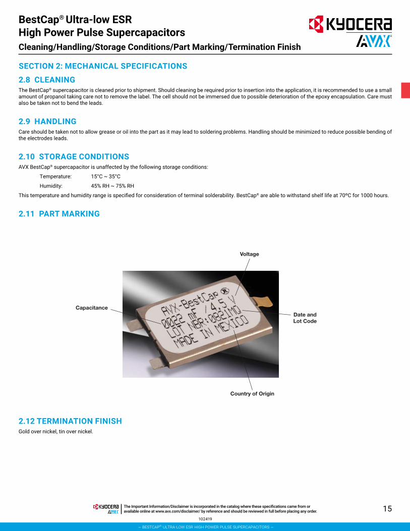
2.11 PART MARKING
Capacitance
Country of Origin
Voltage
Date andLot Code
2.12 TERMINATION FINISHGold over nickel, tin over nickel.
BestCap® Ultra-low ESR High Power Pulse SupercapacitorsCleaning/Handling/Storage Conditions/Part Marking/Termination Finish
102419
– bestcap® ultra-low esr high power pulse supercapacitors –
The Important Information/Disclaimer is incorporated in the catalog where these specifications came from or available online at www.avx.com/disclaimer/ by reference and should be reviewed in full before placing any order.
16
2.13 PRODUCT SAFETY MATERIALS HANDLINGPrecautions• Do not disassemble the capacitor.• Do not incinerate the capacitor and do not use incineration
for disposal.• The capacitor contains polymeric electrolyte and carbon electrodes.
However, since the polymer is composed of acid based chemical ingredients, if punctured or dismantled and the skin is contacted with the capacitor internal components, it is recommended to wash the skin with excess of running water.
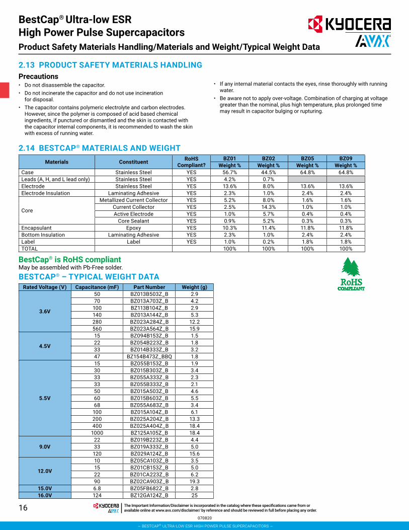
2.14 BESTCAP® MATERIALS AND WEIGHTMaterials Constituent RoHS
Compliant?BZ01 BZ02 BZ05 BZ09
Weight % Weight % Weight % Weight %Case Stainless Steel YES 56.7% 44.5% 64.8% 64.8%Leads (A, H, and L lead only) Stainless Steel YES 4.2% 0.7%Electrode Stainless Steel YES 13.6% 8.0% 13.6% 13.6%Electrode Insulation Laminating Adhesive YES 2.3% 1.0% 2.4% 2.4%
Core
Metallized Current Collector YES 5.2% 8.0% 1.6% 1.6%Current Collector YES 2.5% 14.3% 1.0% 1.0%Active Electrode YES 1.0% 5.7% 0.4% 0.4%
Core Sealant YES 0.9% 5.2% 0.3% 0.3%Encapsulant Epoxy YES 10.3% 11.4% 11.8% 11.8%Bottom Insulation Laminating Adhesive YES 2.3% 1.0% 2.4% 2.4%Label Label YES 1.0% 0.2% 1.8% 1.8%TOTAL 100% 100% 100% 100%
BestCap® is RoHS compliant May be assembled with Pb-Free solder.BESTCAP® – TYPICAL WEIGHT DATA
Rated Voltage (V) Capacitance (mF) Part Number Weight (g)
3.6V
50 BZ013B503Z_B 2.970 BZ013A703Z_B 4.2
100 BZ113B104Z_B 2.9140 BZ013A144Z_B 5.3280 BZ023A284Z_B 12.2560 BZ023A564Z_B 15.9
4.5V
15 BZ094B153Z_B 1.522 BZ054B223Z_B 1.833 BZ014B333Z_B 3.247 BZ154B473Z_BBQ 1.8
5.5V
15 BZ055B153Z_B 1.930 BZ015B303Z_B 3.433 BZ055A333Z_B 2.333 BZ055B333Z_B 2.150 BZ015A503Z_B 4.660 BZ015B603Z_B 5.568 BZ055A683Z_B 3.4
100 BZ015A104Z_B 6.1200 BZ025A204Z_B 13.3400 BZ025A404Z_B 18.4
1000 BZ125A105Z_B 18.4
9.0V22 BZ019B223Z_B 4.433 BZ019A333Z_B 5.0
120 BZ029A124Z_B 15.6
12.0V
10 BZ05CA103Z_B 3.515 BZ01CB153Z_B 5.022 BZ01CA223Z_B 6.290 BZ02CA903Z_B 19.3
15.0V 6.8 BZ05FB682Z_B 2.816.0V 124 BZ12GA124Z_B 25
• If any internal material contacts the eyes, rinse thoroughly with running water.
• Be aware not to apply over-voltage. Combination of charging at voltage greater than the nominal, plus high temperature, plus prolonged time may result in capacitor bulging or rupturing.
BestCap® Ultra-low ESR High Power Pulse SupercapacitorsProduct Safety Materials Handling/Materials and Weight/Typical Weight Data
070820
– bestcap® ultra-low esr high power pulse supercapacitors –
The Important Information/Disclaimer is incorporated in the catalog where these specifications came from or available online at www.avx.com/disclaimer/ by reference and should be reviewed in full before placing any order.
17
SECTION 3Electrical Characteristics
– bestcap® ultra-low esr high power pulse supercapacitors –
The Important Information/Disclaimer is incorporated in the catalog where these specifications came from or available online at www.avx.com/disclaimer/ by reference and should be reviewed in full before placing any order.
18
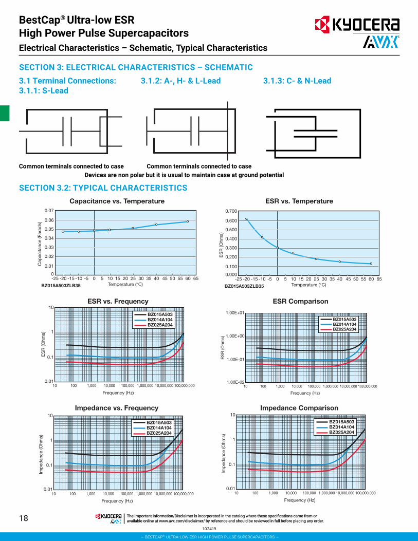
SECTION 3: ELECTRICAL CHARACTERISTICS – SCHEMATIC
SECTION 3.2: TYPICAL CHARACTERISTICS
3.1 Terminal Connections:3.1.1: S-Lead
3.1.2: A-, H- & L-Lead 3.1.3: C- & N-Lead
Common terminals connected to case Common terminals connected to caseDevices are non polar but it is usual to maintain case at ground potential
0.07
0.06
0.05
0.04
0.03
0.02
0.01
0-25 -20 -15 -10 -5 0 5 10 15 20
Temperature (°C)BZ015A503ZLB35
Cap
acita
nce
(Far
ads)
25 30 35 40 45 50 55 60 65
0.700
0.600
0.500
0.400
0.300
0.200
0.100
0.000-25 -20 -15 -10 -5 0 5 10 15 20
Temperature (°C)BZ015A503ZLB35
ES
R (O
hms)
25 30 35 40 45 50 55 60 65
erutarepmeT .sv RSEerutarepmeT .sv ecnaticapaC
10
1
0.1ES
R (O
hms)
0.0110 100 1,000 10,000 100,000 1,000,000 10,000,000
Frequency (Hz)
100,000,000
BZ015A503BZ014A104BZ025A204
ESR vs. Frequency
1.00E+01
1.00E+00
1.00E-01
1.00E-02
ES
R (O
hms)
10 100 1,000 10,000 100,000 1,000,000 10,000,000
Frequency (Hz)
100,000,000
BZ015A503BZ014A104BZ025A204
ESR Comparison
10
1
0.1
0.01
Imp
edan
ce (O
hms)
10 100 1,000 10,000 100,000 1,000,000 10,000,000
Frequency (Hz)
100,000,000
BZ015A503BZ014A104BZ025A204
Impedance vs. Frequency10
1
0.1
0.01
Imp
edan
ce (O
hms)
10 100 1,000 10,000 100,000 1,000,000 10,000,000
Frequency (Hz)
100,000,000
BZ015A503BZ014A104BZ025A204
Impedance Comparison
BestCap® Ultra-low ESR High Power Pulse SupercapacitorsElectrical Characteristics – Schematic, Typical Characteristics
102419
– bestcap® ultra-low esr high power pulse supercapacitors –
The Important Information/Disclaimer is incorporated in the catalog where these specifications came from or available online at www.avx.com/disclaimer/ by reference and should be reviewed in full before placing any order.
19
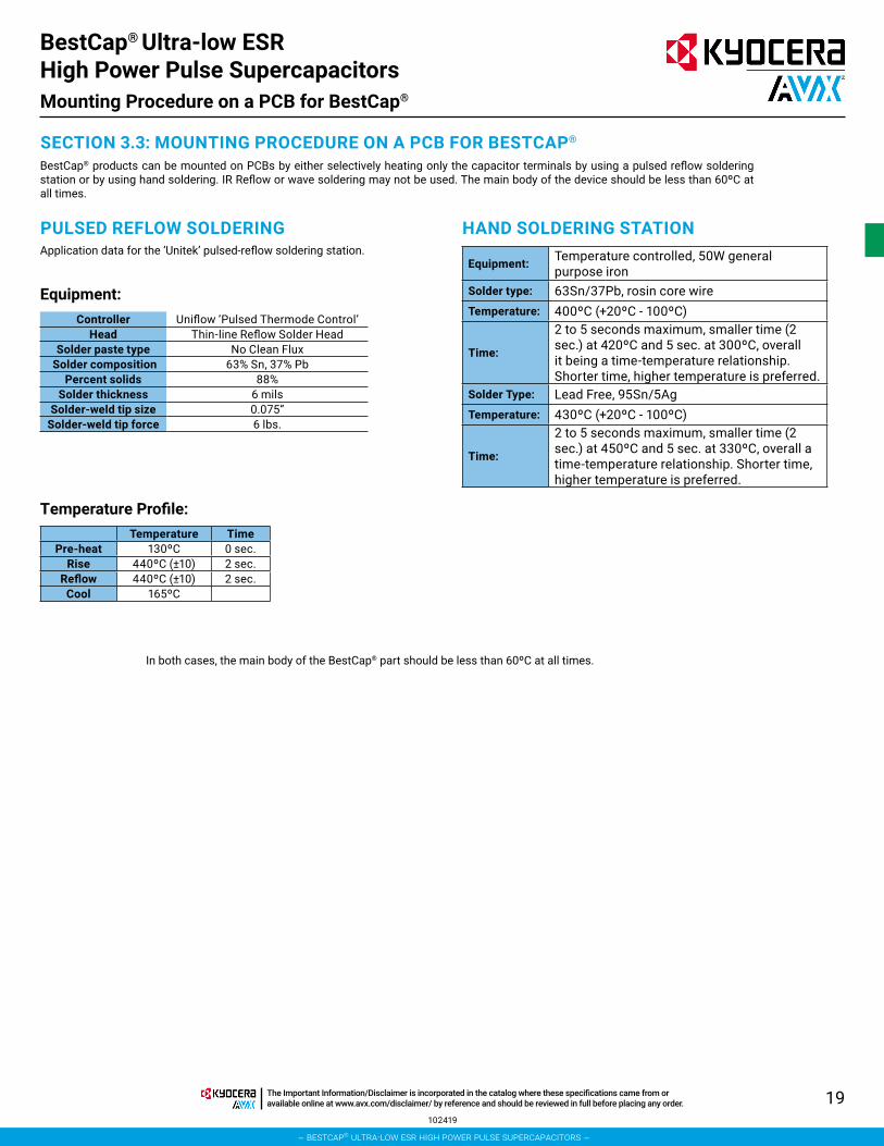
SECTION 3.3: MOUNTING PROCEDURE ON A PCB FOR BESTCAP®
BestCap® products can be mounted on PCBs by either selectively heating only the capacitor terminals by using a pulsed reflow soldering station or by using hand soldering. IR Reflow or wave soldering may not be used. The main body of the device should be less than 60ºC at all times.
PULSED REFLOW SOLDERINGApplication data for the ‘Unitek’ pulsed-reflow soldering station.
Controller Uniflow ‘Pulsed Thermode Control’Head Thin-line Reflow Solder Head
Solder paste type No Clean Flux Solder composition 63% Sn, 37% Pb
Percent solids 88%Solder thickness 6 mils
Solder-weld tip size 0.075”Solder-weld tip force 6 lbs.
Temperature TimePre-heat 130ºC 0 sec.
Rise 440ºC (±10) 2 sec.Reflow 440ºC (±10) 2 sec.
Cool 165ºC
In both cases, the main body of the BestCap® part should be less than 60ºC at all times.
HAND SOLDERING STATION
Temperature Profile:
Equipment:
Equipment: Temperature controlled, 50W general purpose iron
Solder type: 63Sn/37Pb, rosin core wireTemperature: 400ºC (+20ºC - 100ºC)
Time:
2 to 5 seconds maximum, smaller time (2 sec.) at 420ºC and 5 sec. at 300ºC, overall it being a time-temperature relationship. Shorter time, higher temperature is preferred.
Solder Type: Lead Free, 95Sn/5AgTemperature: 430ºC (+20ºC - 100ºC)
Time:
2 to 5 seconds maximum, smaller time (2 sec.) at 450ºC and 5 sec. at 330ºC, overall a time-temperature relationship. Shorter time, higher temperature is preferred.
BestCap® Ultra-low ESR High Power Pulse SupercapacitorsMounting Procedure on a PCB for BestCap®
102419
– bestcap® ultra-low esr high power pulse supercapacitors –
The Important Information/Disclaimer is incorporated in the catalog where these specifications came from or available online at www.avx.com/disclaimer/ by reference and should be reviewed in full before placing any order.
20
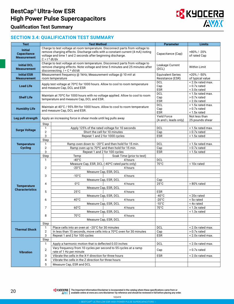
SECTION 3.4: QUALIFICATION TEST SUMMARYTest Test Method Parameter Limits
Initial Capacitance
Measurement
Charge to test voltage at room temperature. Disconnect parts from voltage to remove charging effects. Discharge cells with a constant current (4 mA) noting voltage and time 1 and 2 seconds after beginning discharge. C = I * dt/dv
Capacitance (Cap) +80% / -20%of rated Cap
Initial DCL Measurement
Charge to test voltage at room temperature. Disconnect parts from voltage to remove charging effects. Note voltage and time 5 minutes and 25 minutes after disconnecting. I = C * dV/dt
Leakage Current (DCL) Within Limit
Initial ESR Measurement
Measurement frequency @ 1kHz; Measurement voltage @ 10 mV at room temperature
Equivalent Series Resistance (ESR)
+20% / -50%of typical value
Load Life Apply test voltage at 70ºC for 1000 hours. Allow to cool to room temperature and measure Cap, DCL and ESR
DCLCap ESR
< 2.0x rated max.> 0.7x rated< 3.0x rated
Shelf Life Maintain at 70ºC for 1000 hours with no voltage applied. Allow to cool to room temperature and measure Cap, DCL and ESR.
DCLCap ESR
< 1.5x rated max.> 0.7x rated< 2.0x rated
Humidity Life Maintain at 40°C / 95% RH for 1000 hours. Allow to cool to room temperature and measure Cap, DCL and ESR.
DCLCap ESR
< 1.5x rated max.> 0.7x rated< 1.5x rated
Leg pull strength Apply an increasing force in shear mode until leg pulls away Yield Force(A and L leads only)
Not less than25 pounds shear
Surge Voltage
Step1 Apply 125% of the rated voltage for 10 seconds DCL < 1.5x rated max.2 Short the cell for 10 minutes Cap > 0.7x rated3 Repeat 1 and 2 for 1000 cycles ESR < 1.5x rated
Temperature Cycling
Step1 Ramp oven down to –20°C and then hold for 15 min. DCL < 1.5x rated max.2 Ramp oven up to 70ºC and then hold for 15 min. Cap > 0.7x rated3 Repeat 1 and 2 for 100 cycles ESR < 1.5x rated
Temperature Characteristics
Step Temp Soak Time (prior to test)1 -40°C 4 hours DCL
Measure Cap, ESR, DCL (-40ºC rated parts only) 70°C < 10x rated2 -20°C 4 hours
Measure Cap, ESR, DCL3 -10°C 4 hours
Measure Cap, ESR, DCL Cap4 0°C 4 hours 25°C > 80% rated
Measure Cap, ESR, DCL5 25°C 4 hours ESR
Measure Cap, ESR, DCL -40°C < 20x rated6 40°C 4 hours -20°C < 5x rated
Measure Cap, ESR, DCL -10°C < 4x rated7 60°C 4 hours 70°C < 1.3x rated
Measure Cap, ESR, DCL < 1.3x rated8 70°C 4 hours
Measure Cap, ESR, DCL
Thermal Shock
Step1 Place cells into an oven at –20°C for 30 minutes DCL < 2.0x rated max.2 In less than 15 seconds, move cells into a 70ºC oven for 30 minutes Cap > 0.7x rated3 Repeat 1 and 2 for 100 cycles ESR < 2.0x rated max.
Vibration
Step1 Apply a harmonic motion that is deflected 0.03 inches DCL < 2.0x rated max.
2 Vary frequency from 10 cycles per second to 55 cycles at a ramp rate of 1 Hz per minute Cap > 0.7x rated
3 Vibrate the cells in the X-Y direction for three hours ESR < 2.0x rated max.4 Vibrate the cells in the Z direction for three hours5 Measure Cap, ESR and DCL
BestCap® Ultra-low ESR High Power Pulse SupercapacitorsQualification Test Summary
102419
– bestcap® ultra-low esr high power pulse supercapacitors –
The Important Information/Disclaimer is incorporated in the catalog where these specifications came from or available online at www.avx.com/disclaimer/ by reference and should be reviewed in full before placing any order.

21
SECTION 4Application Notes
– bestcap® ultra-low esr high power pulse supercapacitors –
The Important Information/Disclaimer is incorporated in the catalog where these specifications came from or available online at www.avx.com/disclaimer/ by reference and should be reviewed in full before placing any order.
22
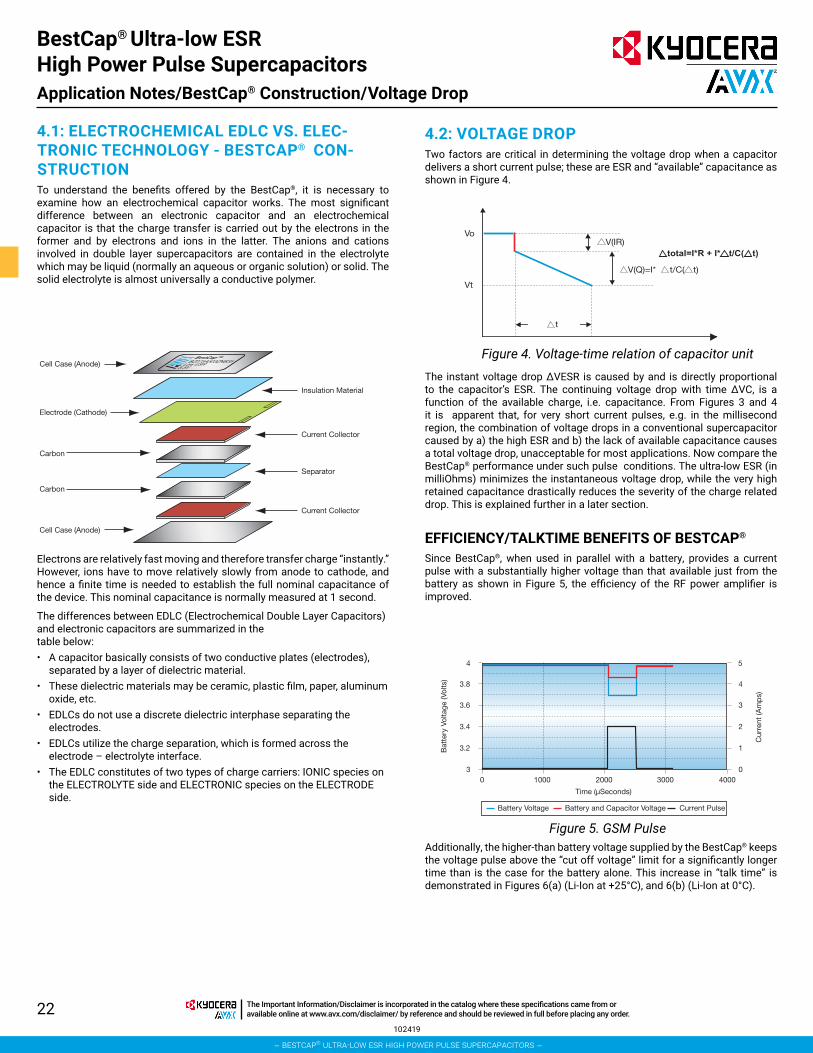
4.1: ELECTROCHEMICAL EDLC VS. ELEC-TRONIC TECHNOLOGY - BESTCAP® CON-STRUCTIONTo understand the benefits offered by the BestCap®, it is necessary to examine how an electrochemical capacitor works. The most significant difference between an electronic capacitor and an electrochemical capacitor is that the charge transfer is carried out by the electrons in the former and by electrons and ions in the latter. The anions and cations involved in double layer supercapacitors are contained in the electrolyte which may be liquid (normally an aqueous or organic solution) or solid. The solid electrolyte is almost universally a conductive polymer.
Cell Case (Anode)
Cell Case (Anode)
Electrode (Cathode)
Carbon
Carbon
Insulation Material
Current Collector
Current Collector
Separator
Vo
Vt
t
V(IR)
V(Q)=I* t/C( t)
total=I*R + I* t/C( t)
3.6
3.4
3.2
30 1000 2000 3000 4000
3.8
4
3
2
1
0
4
5
Bat
tery
Vol
tage
(Vol
ts)
Cur
rent
(Am
ps)
Time (µSeconds)
Battery Voltage Battery and Capacitor Voltage Current Pulse
Electrons are relatively fast moving and therefore transfer charge “instantly.” However, ions have to move relatively slowly from anode to cathode, and hence a finite time is needed to establish the full nominal capacitance of the device. This nominal capacitance is normally measured at 1 second.
The differences between EDLC (Electrochemical Double Layer Capacitors) and electronic capacitors are summarized in the table below:• A capacitor basically consists of two conductive plates (electrodes),
separated by a layer of dielectric material.• These dielectric materials may be ceramic, plastic film, paper, aluminum
oxide, etc.• EDLCs do not use a discrete dielectric interphase separating the
electrodes.• EDLCs utilize the charge separation, which is formed across the
electrode – electrolyte interface.• The EDLC constitutes of two types of charge carriers: IONIC species on
the ELECTROLYTE side and ELECTRONIC species on the ELECTRODE side.
4.2: VOLTAGE DROPTwo factors are critical in determining the voltage drop when a capacitor delivers a short current pulse; these are ESR and “available” capacitance as shown in Figure 4.
Figure 4. Voltage-time relation of capacitor unit
Figure 5. GSM Pulse
The instant voltage drop ∆VESR is caused by and is directly proportional to the capacitor’s ESR. The continuing voltage drop with time ∆VC, is a function of the available charge, i.e. capacitance. From Figures 3 and 4 it is apparent that, for very short current pulses, e.g. in the millisecond region, the combination of voltage drops in a conventional supercapacitor caused by a) the high ESR and b) the lack of available capacitance causes a total voltage drop, unacceptable for most applications. Now compare the BestCap® performance under such pulse conditions. The ultra-low ESR (in milliOhms) minimizes the instantaneous voltage drop, while the very high retained capacitance drastically reduces the severity of the charge related drop. This is explained further in a later section. EFFICIENCY/TALKTIME BENEFITS OF BESTCAP®
Since BestCap®, when used in parallel with a battery, provides a current pulse with a substantially higher voltage than that available just from the battery as shown in Figure 5, the efficiency of the RF power amplifier is improved.
Additionally, the higher-than battery voltage supplied by the BestCap® keeps the voltage pulse above the “cut off voltage” limit for a significantly longer time than is the case for the battery alone. This increase in “talk time” is demonstrated in Figures 6(a) (Li-Ion at +25°C), and 6(b) (Li-Ion at 0°C).
BestCap® Ultra-low ESR High Power Pulse SupercapacitorsApplication Notes/BestCap® Construction/Voltage Drop
102419
– bestcap® ultra-low esr high power pulse supercapacitors –
The Important Information/Disclaimer is incorporated in the catalog where these specifications came from or available online at www.avx.com/disclaimer/ by reference and should be reviewed in full before placing any order.

23
PULSE CAPACITOR APPLICATIONSAs mentioned earlier, the voltage drop in a circuit is critical as the circuit will not operate below a certain cut-off voltage. There are two sources of voltage drop (∆V) which occur, the first ∆VESR is because of the equivalent series resistance (ESR) and the second, called the capacitive drop, is ∆VC. From Ohm’s law,
voltage = current x resistance or V = IR
Let us say that the instantaneous starting voltage is Vo, or voltage for the circuit from where the voltage drops. If the capacitor has an ESR of 100 milliOhms and the current is 1 amp,
∆VESR = 1 amp x (0.100) ohms = 0.1 volts or 100 milli-volts. On demand, during the discharge mode, the voltage V = Vo
- ∆VESR = (Vo - 0.1) volts
The second voltage drop is because of the capacitance. This is shown in the equation as a linear function because of simplicity. Simply put,
Q (charge) = C (capacitance) x V (voltage)
The derivative, dQ/dt = I (current, in amps) = C x dV/dt
Hence, ∆VC (dV, the voltage drop because of capacitance) = I x dt/C. This formula states that the larger the capacitance value the lower the voltage drop. Compared to a Ta capacitor, this ∆VC is reduced by a factor of about 10 to 100. So, BestCap® has an advantage where higher capacitance is needed. If the current pulse itself is 1 amp, the current pulse width is 1 second and the capacitance is 10 millifarads, the ∆VC = 1A x 1Sec/0.01F, or a 100 volts; such an application is out of the range of BestCap®. However, if the pulse width becomes narrower, say 10 milliseconds, and the capacitance is 100 millifarads, the ∆VC = 1 x (10/1000)/(100/1000) = 0.1 volt or 100 millivolts. This shows the advantage of the large capacitance and hence the term “pulse” capacitor. The specific power – specific energy graphs are used in the battery industry to compare competitive products. As the dt becomes smaller i.e.100 milliseconds, 10 milliseconds and then 1 millisecond, our estimates show that the specific power for the BestCap® is the highest as compared to our competitors because of our choice of internal materials chemistry.
Conclusion: we now clearly show that BestCap® has an advantage over competitors for short current pulse whose widths are smaller than a few hundred milliseconds.
Figure 6a. Li-ION Battery at +25°C
Figure 6b. Li-ION Battery at +0°C
2
2.5
3
3.5
4
0 100 200 300 400
Cutoff Voltage Limits
Vol
tage
(Vol
ts)
Cutoff Voltage
3.4 Volts
3.5 Volts
3.6 Volts
Time (Minutes)
% Increase
28%
73%
300%
Battery AloneBattery with Pulse Capacitor
GSM Pulse @ 2 Amps
2
2.5
3
3.5
4
0 100 200 300 400
LI-ION Battery
Vol
tage
(Vol
ts)
500
Cutoff Voltage
3.4 Volts
3.5 Volts
3.6 Volts
Time (Minutes)
% Increase
28%
100%
300%
Battery AloneBattery with Pulse Capacitor
GSM Pulse @ 2 Amps 0°C
BestCap® Ultra-low ESR High Power Pulse Supercapacitors
070820
– bestcap® ultra-low esr high power pulse supercapacitors –
The Important Information/Disclaimer is incorporated in the catalog where these specifications came from or available online at www.avx.com/disclaimer/ by reference and should be reviewed in full before placing any order.
24
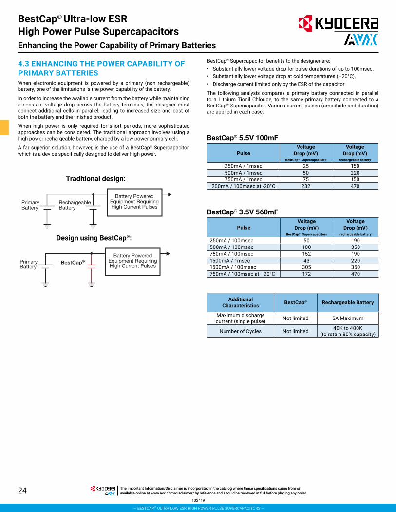
4.3 ENHANCING THE POWER CAPABILITY OF PRIMARY BATTERIESWhen electronic equipment is powered by a primary (non rechargeable) battery, one of the limitations is the power capability of the battery.
In order to increase the available current from the battery while maintaining a constant voltage drop across the battery terminals, the designer must connect additional cells in parallel, leading to increased size and cost of both the battery and the finished product.
When high power is only required for short periods, more sophisticated approaches can be considered. The traditional approach involves using a high power rechargeable battery, charged by a low power primary cell.
A far superior solution, however, is the use of a BestCap® Supercapacitor, which is a device specifically designed to deliver high power.
Traditional design:
Design using BestCap®:
PrimaryBattery
RechargeableBattery
Battery PoweredEquipment RequiringHigh Current Pulses
PrimaryBattery
BestCapBattery Powered
Equipment RequiringHigh Current Pulses
®
BestCap® Supercapacitor benefits to the designer are:• Substantially lower voltage drop for pulse durations of up to 100msec.• Substantially lower voltage drop at cold temperatures (–20°C).• Discharge current limited only by the ESR of the capacitor
The following analysis compares a primary battery connected in parallel to a Lithium Tionil Chloride, to the same primary battery connected to a BestCap® Supercapacitor. Various current pulses (amplitude and duration) are applied in each case.
BestCap® 5.5V 100mF
BestCap® 3.5V 560mF
PulseVoltage
Drop (mV)BestCap® Supercapacitors
Voltage Drop (mV)
rechargeable battery
250mA / 1msec 25 150500mA / 1msec 50 220750mA / 1msec 75 150
200mA / 100msec at -20°C 232 470
PulseVoltage
Drop (mV)BestCap® Supercapacitors
Voltage Drop (mV)
rechargeable battery
250mA / 100msec 50 190500mA / 100msec 100 350750mA / 100msec 152 1901500mA / 1msec 43 2201500mA / 100msec 305 350750mA / 100msec at –20°C 172 470
Additional Characteristics BestCap® Rechargeable Battery
Maximum discharge current (single pulse) Not limited 5A Maximum
Number of Cycles Not limited 40K to 400K (to retain 80% capacity)
BestCap® Ultra-low ESR High Power Pulse SupercapacitorsEnhancing the Power Capability of Primary Batteries
102419
– bestcap® ultra-low esr high power pulse supercapacitors –
The Important Information/Disclaimer is incorporated in the catalog where these specifications came from or available online at www.avx.com/disclaimer/ by reference and should be reviewed in full before placing any order.
25
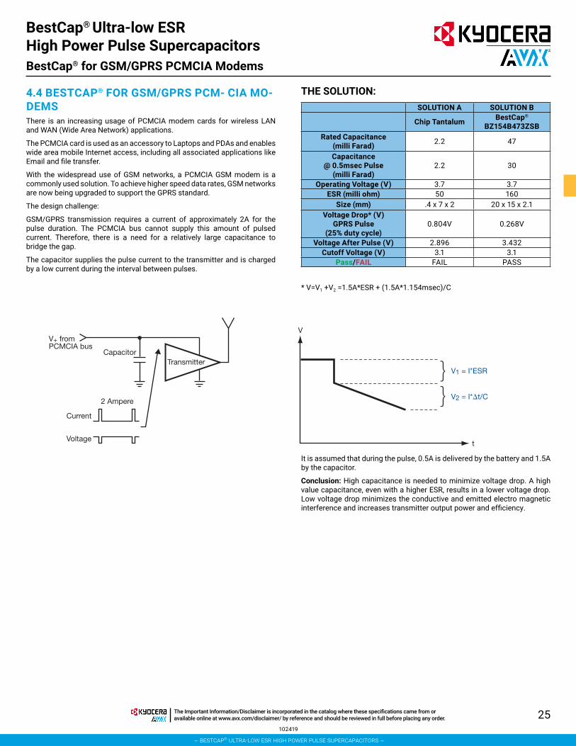
4.4 BESTCAP® FOR GSM/GPRS PCM- CIA MO-DEMSThere is an increasing usage of PCMCIA modem cards for wireless LAN and WAN (Wide Area Network) applications.
The PCMCIA card is used as an accessory to Laptops and PDAs and enables wide area mobile Internet access, including all associated applications like Email and file transfer.
With the widespread use of GSM networks, a PCMCIA GSM modem is a commonly used solution. To achieve higher speed data rates, GSM networks are now being upgraded to support the GPRS standard.
The design challenge:
GSM/GPRS transmission requires a current of approximately 2A for the pulse duration. The PCMCIA bus cannot supply this amount of pulsed current. Therefore, there is a need for a relatively large capacitance to bridge the gap.
The capacitor supplies the pulse current to the transmitter and is charged by a low current during the interval between pulses.
Capacitor
2 Ampere
Current
Voltage
V+ fromPCMCIA bus
Transmitter
V
t
V1 = I*ESR
V2 = I* t/C
} }
THE SOLUTION:SOLUTION A SOLUTION B
Chip Tantalum BestCap® BZ154B473ZSB
Rated Capacitance (milli Farad) 2.2 47
Capacitance @ 0.5msec Pulse
(milli Farad)2.2 30
Operating Voltage (V) 3.7 3.7ESR (milli ohm) 50 160
Size (mm) .4 x 7 x 2 20 x 15 x 2.1Voltage Drop* (V)
GPRS Pulse (25% duty cycle)
0.804V 0.268V
Voltage After Pulse (V) 2.896 3.432Cutoff Voltage (V) 3.1 3.1
Pass/FAIL FAIL PASS
* V=V1 +V2 =1.5A*ESR + (1.5A*1.154msec)/C
It is assumed that during the pulse, 0.5A is delivered by the battery and 1.5A by the capacitor.
Conclusion: High capacitance is needed to minimize voltage drop. A high value capacitance, even with a higher ESR, results in a lower voltage drop. Low voltage drop minimizes the conductive and emitted electro magnetic interference and increases transmitter output power and efficiency.
BestCap® Ultra-low ESR High Power Pulse SupercapacitorsBestCap® for GSM/GPRS PCMCIA Modems
102419
– bestcap® ultra-low esr high power pulse supercapacitors –
The Important Information/Disclaimer is incorporated in the catalog where these specifications came from or available online at www.avx.com/disclaimer/ by reference and should be reviewed in full before placing any order.
26
SECTION 5Extended Temperature Range
– bestcap® ultra-low esr high power pulse supercapacitors –
The Important Information/Disclaimer is incorporated in the catalog where these specifications came from or available online at www.avx.com/disclaimer/ by reference and should be reviewed in full before placing any order.

27
SECTION 5: EXTENDED TEMPERATURE RANGEAVX continues to expand the BestCap® product offerings for additional applications. For applications demanding other temperature ratings, AVX offers special construction techniques for high and low temperature performance upon request.
AVX offers temperature range extensions as follows: • -40ºC to 70ºC, -20ºC to 75ºC and -40ºC to 75ºC.
AVX has extensive experience in manufacturing these alternate temperature rating parts. Contact AVX for your special temperature requirements.
BestCap® Ultra-low ESR High Power Pulse SupercapacitorsExtended Temperature Range
102419
– bestcap® ultra-low esr high power pulse supercapacitors –
The Important Information/Disclaimer is incorporated in the catalog where these specifications came from or available online at www.avx.com/disclaimer/ by reference and should be reviewed in full before placing any order.
28
PASSIVESCapacitorsMultilayer Ceramic
Film
Glass
Niobium Oxide* - OxiCap®
Pulse Supercapacitors
Tantalum
Circuit ProtectionThermistors
Fuses - Thin Film
Transient Voltage Suppressors
Varistors - Zinc Oxide
Directional CouplersThin-Film
FiltersCeramic
EMI
Noise
SAW
Low Pass - Thin Film
InductorsThin-Film
Integrated Passive ComponentsPMC - Thin-Film Networks
Capacitor Arrays
Feedthru Arrays
Low Inductance Decoupling Arrays
Piezo Acoustic GeneratorsCeramic
ResistorsArrays
Miniature Axials
Timing DevicesClock Oscillators
MHz Quartz Crystal
Resonators
VCO
TCXO
CONNECTORSAutomotive Standard, Custom
Board to Board SMD (0.4, 0.5, 1.0mm), BGA, Thru-Hole
Card Edge
DIN41612 Standard, Inverse, High Temperature
FFC/FPC 0.3, 0.5, 1.0mm
Hand Held, Cellular Battery, I/O, SIMcard, RF shield clips
2mm Hard Metric Standard, Reduced Cross-Talk
IDC Wire to Board Headers, Plugs, Assemblies
Memory PCMCIA, Compact Flash, Secure Digital, MMC, Smartcard, SODIMM
Military H Government, DIN41612
PolytectTM Soft Molding
Rack and Panel VariconTM
NOTICE: Specifications are subject to change without notice. Contact your nearest AVX Sales Office for the latest specifications. All statements, information and data given herein are believed to be accurate and reliable, but are presented without guarantee, warranty, or responsibility of any kind, expressed or implied. Statements or suggestions concerning possible use of our products are made without representation or warranty that any such use is free of patent infringement and are not recom-mendations to infringe any patent. The user should not assume that all safety measures are indicated or that other measures may not be required. Specifications are typical and may not apply to all applications.
© AVX Corporation
“Niobium Oxide Capacitors are manufactured and sold under patent license from Cabot Corporation, Boyertown, Pennsylvania U.S.A.”
BestCap® Ultra-low ESR High Power Pulse SupercapacitorsProduct Listing
– bestcap® ultra-low esr high power pulse supercapacitors –
The Important Information/Disclaimer is incorporated in the catalog where these specifications came from or available online at www.avx.com/disclaimer/ by reference and should be reviewed in full before placing any order.

North AmericaTel: +1 864-967-2150
Central AmericaTel: +55 11-46881960
AsiaTel: +65 6286-7555
JapanTel: +81 740-321250
EuropeTel: +44 1276-697000
visit us at www.kyocera-avx.com
FOLLOW US: