Embed Size (px)
Citation preview
1 © 2016 ANSYS, Inc. July 19, 2017
Best Practices for Contact Modeling using ANSYS
This presentation contains ANSYS, Inc. proprietary information.
It is not to be distributed to others.
Yongyi Zhu, PhD
Research and Development Fellow
July, 2017
2 © 2016 ANSYS, Inc. July 19, 2017
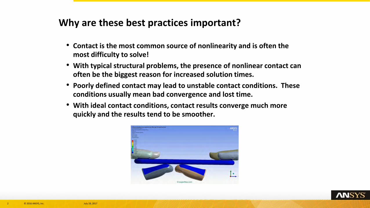
Why are these best practices important?
• Contact is the most common source of nonlinearity and is often the most difficulty to solve!
• With typical structural problems, the presence of nonlinear contact can often be the biggest reason for increased solution times.
• Poorly defined contact may lead to unstable contact conditions. These conditions usually mean bad convergence and lost time.
• With ideal contact conditions, contact results converge much more quickly and the results tend to be smoother.
3 © 2016 ANSYS, Inc. July 19, 2017
• Section 1: Contact Model Setup and Verification:
– Contact Generation and Management Tips
• Section 2: Getting Ready for the Solver:
– Mesh Quality & Mesh Sizing
– Setting the Contact Formulation
– Understanding the Effect of Contact Stiffness
– Advantages of MPC Contact
– Specifying Pinball Radius
– Initial Interface Adjustment
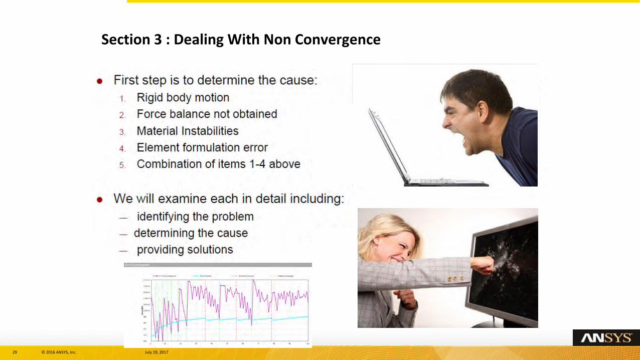
• Section 3: Dealing With Non Convergence
– Diagnostic Tools
– Contact Results Tool
– Overcoming Rigid Body Motions
– Procedure for Overcoming Convergence Difficulties
What this presentation will cover
4 © 2016 ANSYS, Inc. July 19, 2017
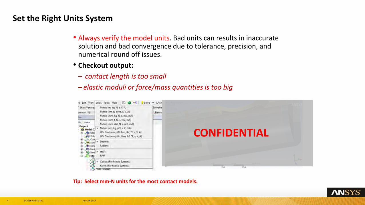
• Always verify the model units. Bad units can results in inaccurate solution and bad convergence due to tolerance, precision, and numerical round off issues.
• Checkout output:
– contact length is too small
– elastic moduli or force/mass quantities is too big
Tip: Select mm-N units for the most contact models.
Set the Right Units System
CONFIDENTIAL
5 © 2016 ANSYS, Inc. July 19, 2017
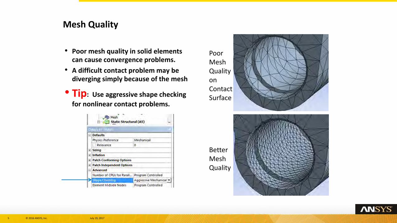
• Poor mesh quality in solid elements can cause convergence problems.
• A difficult contact problem may be diverging simply because of the mesh
• Tip: Use aggressive shape checking
for nonlinear contact problems.
Mesh Quality
Poor Mesh Quality on Contact Surface
Better Mesh Quality
6 © 2016 ANSYS, Inc. July 19, 2017
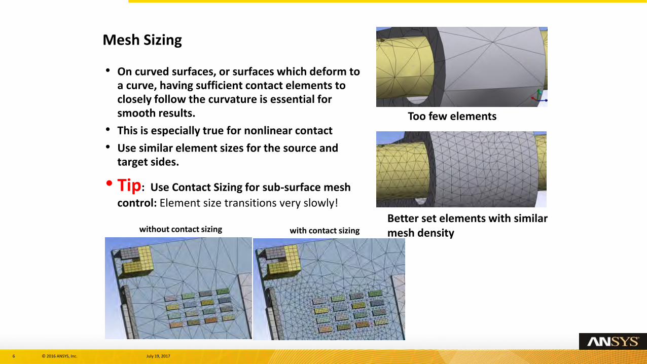
• On curved surfaces, or surfaces which deform to a curve, having sufficient contact elements to closely follow the curvature is essential for smooth results.
• This is especially true for nonlinear contact
• Use similar element sizes for the source and target sides.
• Tip: Use Contact Sizing for sub-surface mesh
control: Element size transitions very slowly!
Mesh Sizing
Too few elements
Better set elements with similar mesh densitywithout contact sizing with contact sizing
7 © 2016 ANSYS, Inc. July 19, 2017
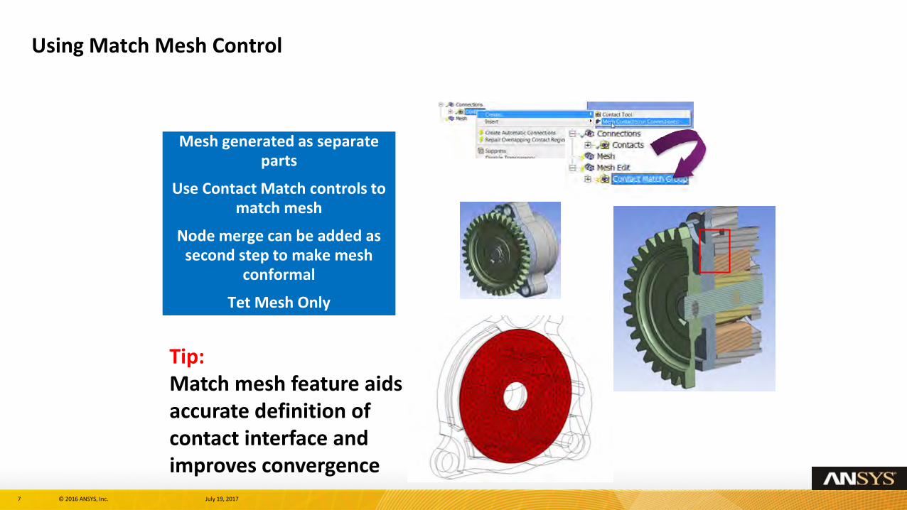
Using Match Mesh Control
Mesh generated as separate parts
Use Contact Match controls to match mesh
Node merge can be added as second step to make mesh
conformal
Tet Mesh Only
Tip: Match mesh feature aids accurate definition of contact interface and improves convergence
8 © 2016 ANSYS, Inc. July 19, 2017
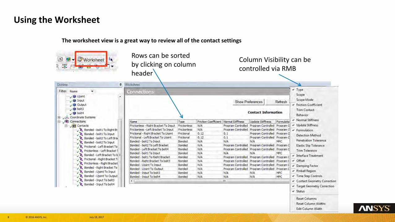
Using the Worksheet
The worksheet view is a great way to review all of the contact settings
Column Visibility can be controlled via RMB
Rows can be sorted by clicking on column header
9 © 2016 ANSYS, Inc. July 19, 2017
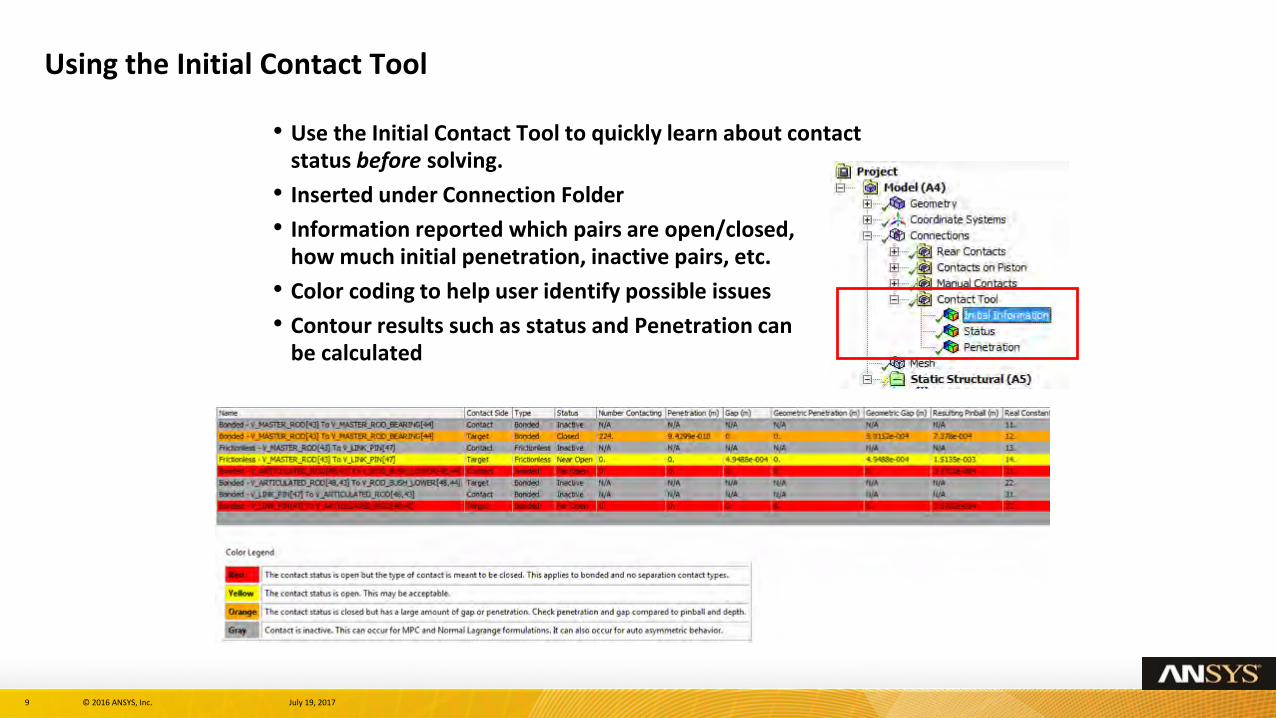
Using the Initial Contact Tool
• Use the Initial Contact Tool to quickly learn about contact status before solving.
• Inserted under Connection Folder
• Information reported which pairs are open/closed, how much initial penetration, inactive pairs, etc.
• Color coding to help user identify possible issues
• Contour results such as status and Penetration can be calculated
10 © 2016 ANSYS, Inc. July 19, 2017
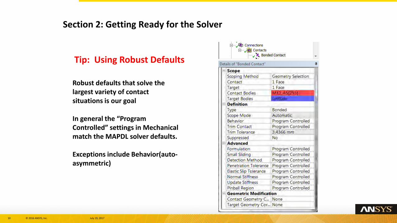
Section 2: Getting Ready for the Solver
Robust defaults that solve the largest variety of contact situations is our goal
In general the “Program Controlled” settings in Mechanical match the MAPDL solver defaults.
Exceptions include Behavior(auto-asymmetric)
Tip: Using Robust Defaults
11 © 2016 ANSYS, Inc. July 19, 2017
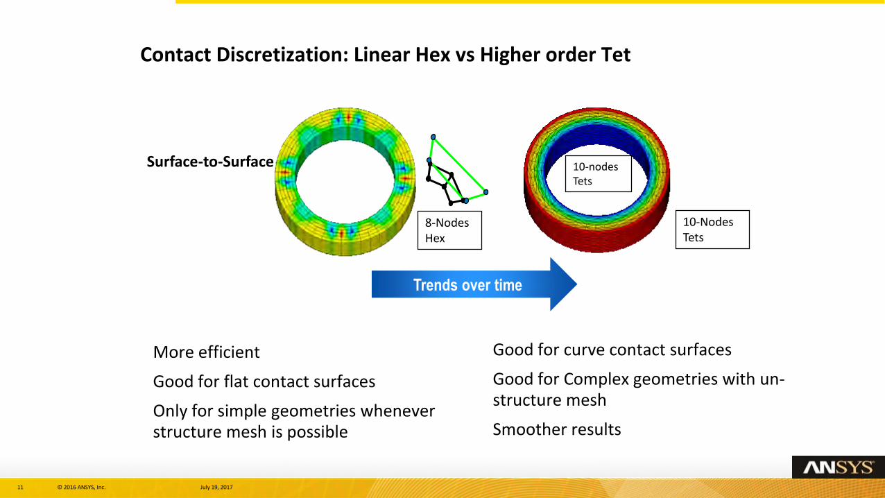
Contact Discretization: Linear Hex vs Higher order Tet
Trends over time
8-Nodes Hex
10-Nodes Tets
Surface-to-Surface 10-nodes Tets
More efficient
Good for flat contact surfaces
Only for simple geometries whenever structure mesh is possible
Good for curve contact surfaces
Good for Complex geometries with un-structure mesh
Smoother results
12 © 2016 ANSYS, Inc. July 19, 2017
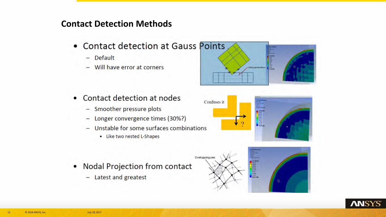
Contact Detection Methods
13 © 2016 ANSYS, Inc. July 19, 2017
• Surface integration point method allow for additional points to detect penetration between surfaces - Default method for Penalty and Augmented Lagrange method.
– However it is poor when contact occurs at corners or edges.
• Nodal based detection methods are default for MPC and Normal Lagrange method.
– For contacts at corners (such as interference fit problems, threaded connector models), best results are obtained when either Nodal – Normal to Target (or) Normal for Contact.
• Nodal – Projected Normal From Contact
– For true surface-surface contacts, it provides good results with minimal contact pressure spikes at nodes
– Convergence behavior is also better if mesh is adequately discretized at contact surfaces.
– For best performance, use similar mesh size for both contact and target surfaces.
Contact Detection Methods: Notes
14 © 2016 ANSYS, Inc. July 19, 2017
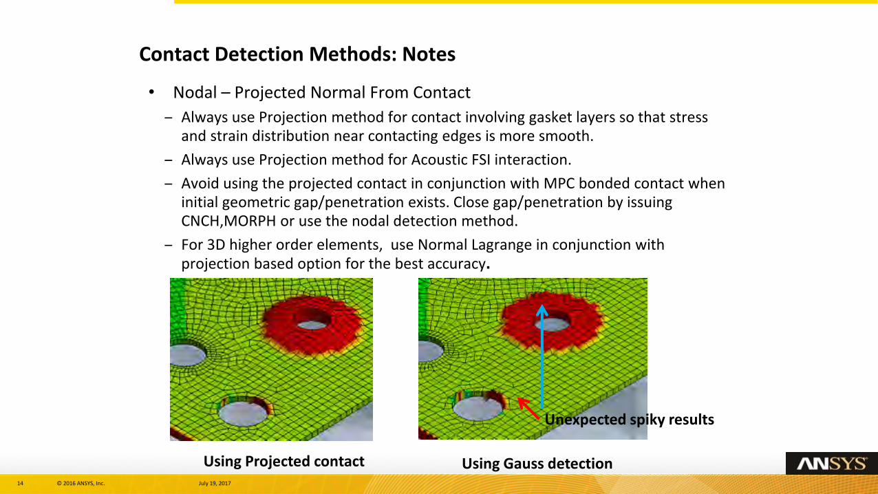
• Nodal – Projected Normal From Contact
– Always use Projection method for contact involving gasket layers so that stress and strain distribution near contacting edges is more smooth.
– Always use Projection method for Acoustic FSI interaction.
– Avoid using the projected contact in conjunction with MPC bonded contact when initial geometric gap/penetration exists. Close gap/penetration by issuing CNCH,MORPH or use the nodal detection method.
– For 3D higher order elements, use Normal Lagrange in conjunction with projection based option for the best accuracy.
Contact Detection Methods: Notes
Unexpected spiky results
Using Gauss detectionUsing Projected contact
15 © 2016 ANSYS, Inc. July 19, 2017
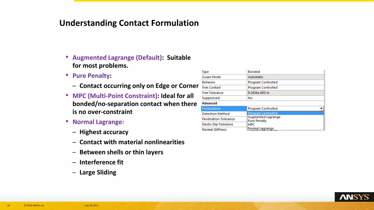
• Augmented Lagrange (Default): Suitable for most problems.
• Pure Penalty:
– Contact occurring only on Edge or Corner
• MPC (Multi-Point Constraint): Ideal for all bonded/no-separation contact when there is no over-constraint
• Normal Lagrange:
– Highest accuracy
– Contact with material nonlinearities
– Between shells or thin layers
– Interference fit
– Large Sliding
Understanding Contact Formulation
16 © 2016 ANSYS, Inc. July 19, 2017
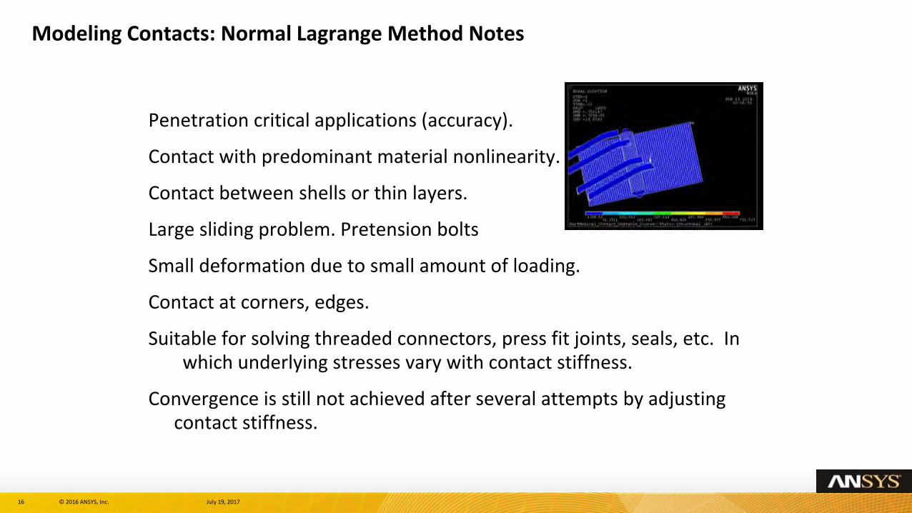
Penetration critical applications (accuracy).
Contact with predominant material nonlinearity.
Contact between shells or thin layers.
Large sliding problem. Pretension bolts
Small deformation due to small amount of loading.
Contact at corners, edges.
Suitable for solving threaded connectors, press fit joints, seals, etc. In which underlying stresses vary with contact stiffness.
Convergence is still not achieved after several attempts by adjusting contact stiffness.
Modeling Contacts: Normal Lagrange Method Notes
17 © 2016 ANSYS, Inc. July 19, 2017
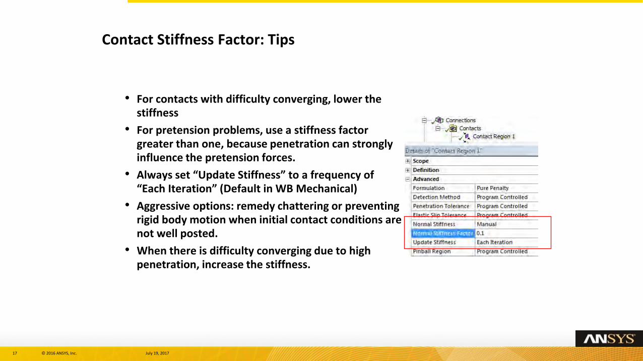
• For contacts with difficulty converging, lower the stiffness
• For pretension problems, use a stiffness factor greater than one, because penetration can strongly influence the pretension forces.
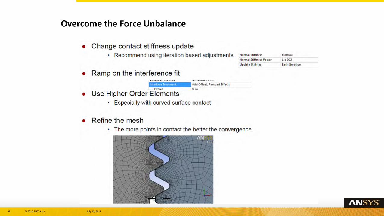
• Always set “Update Stiffness” to a frequency of “Each Iteration” (Default in WB Mechanical)
• Aggressive options: remedy chattering or preventing rigid body motion when initial contact conditions are not well posted.
• When there is difficulty converging due to high penetration, increase the stiffness.
Contact Stiffness Factor: Tips
18 © 2016 ANSYS, Inc. July 19, 2017
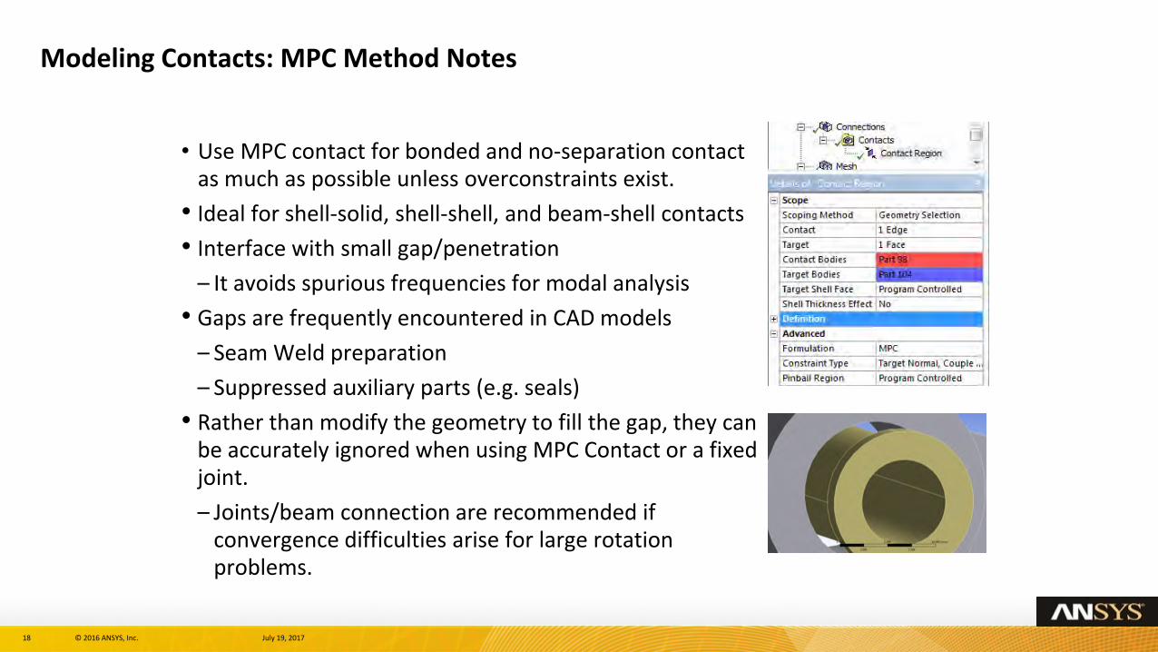
Modeling Contacts: MPC Method Notes
• Use MPC contact for bonded and no-separation contact as much as possible unless overconstraints exist.
• Ideal for shell-solid, shell-shell, and beam-shell contacts
• Interface with small gap/penetration
– It avoids spurious frequencies for modal analysis
• Gaps are frequently encountered in CAD models
– Seam Weld preparation
– Suppressed auxiliary parts (e.g. seals)
• Rather than modify the geometry to fill the gap, they can be accurately ignored when using MPC Contact or a fixed joint.
– Joints/beam connection are recommended if convergence difficulties arise for large rotation problems.
19 © 2016 ANSYS, Inc. July 19, 2017
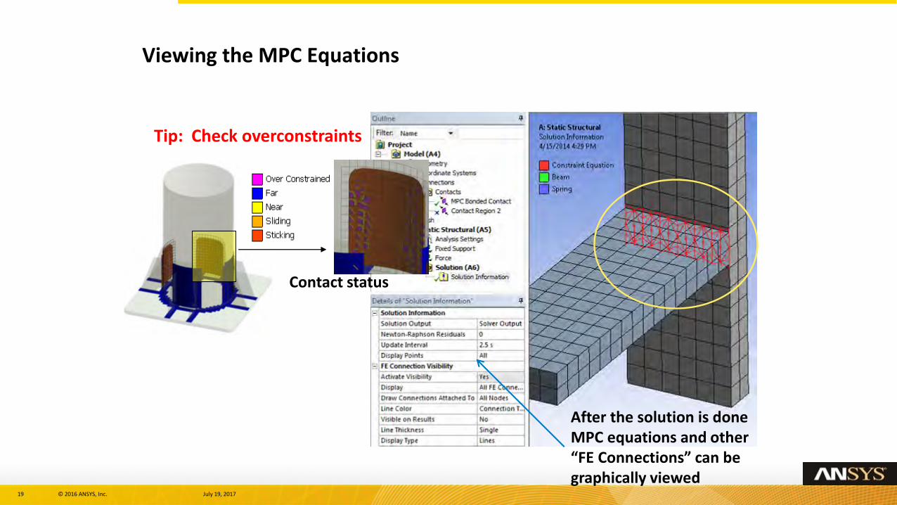
Viewing the MPC Equations
After the solution is done MPC equations and other “FE Connections” can be graphically viewed
Tip: Check overconstraints
Contact status
20 © 2016 ANSYS, Inc. July 19, 2017
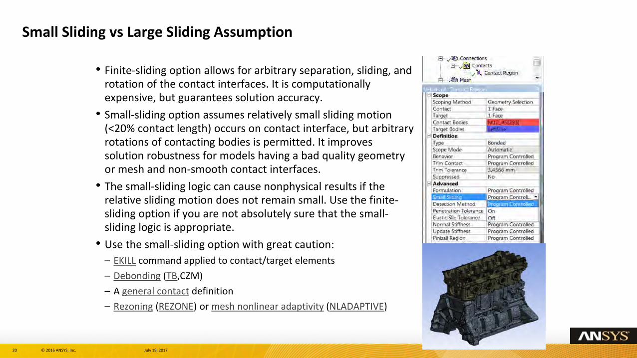
Small Sliding vs Large Sliding Assumption
• Finite-sliding option allows for arbitrary separation, sliding, and rotation of the contact interfaces. It is computationally expensive, but guarantees solution accuracy.
• Small-sliding option assumes relatively small sliding motion (<20% contact length) occurs on contact interface, but arbitrary rotations of contacting bodies is permitted. It improves solution robustness for models having a bad quality geometry or mesh and non-smooth contact interfaces.
• The small-sliding logic can cause nonphysical results if the relative sliding motion does not remain small. Use the finite-sliding option if you are not absolutely sure that the small-sliding logic is appropriate.
• Use the small-sliding option with great caution:
– EKILL command applied to contact/target elements
– Debonding (TB,CZM)
– A general contact definition
– Rezoning (REZONE) or mesh nonlinear adaptivity (NLADAPTIVE)
21 © 2016 ANSYS, Inc. July 19, 2017
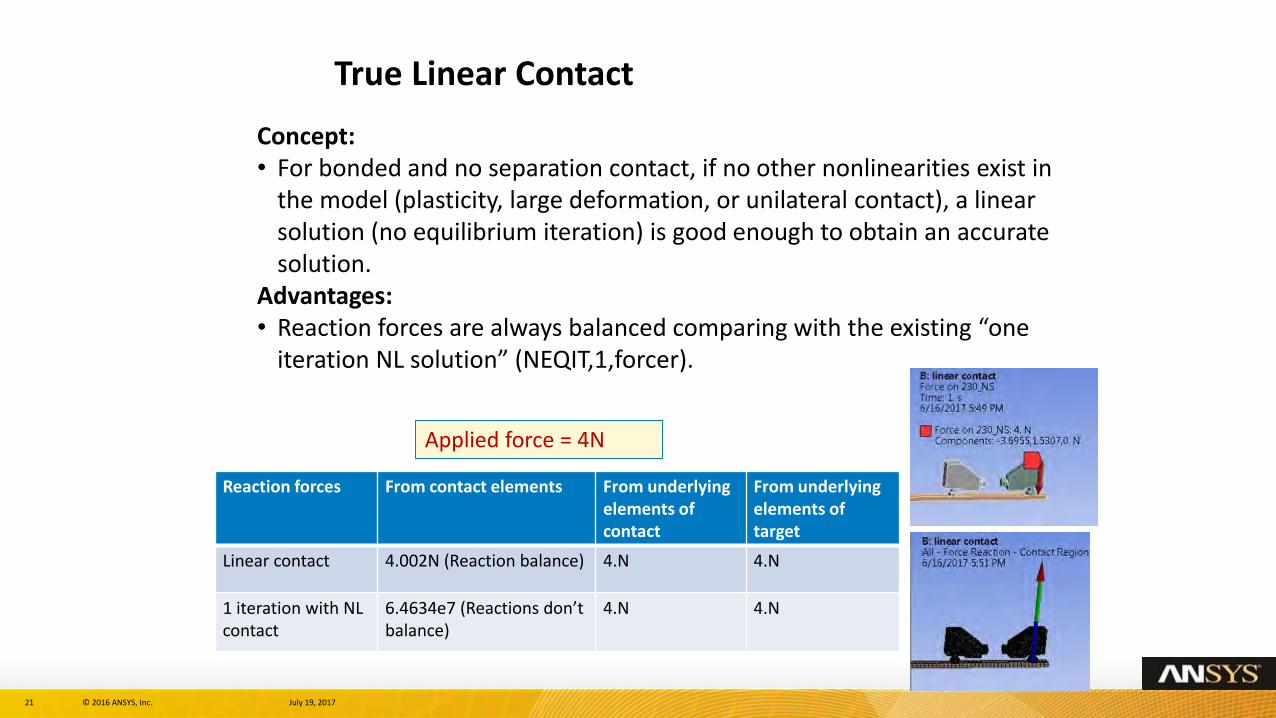
True Linear Contact
Concept: • For bonded and no separation contact, if no other nonlinearities exist in
the model (plasticity, large deformation, or unilateral contact), a linear solution (no equilibrium iteration) is good enough to obtain an accurate solution.
Advantages: • Reaction forces are always balanced comparing with the existing “one
iteration NL solution” (NEQIT,1,forcer).
Reaction forces From contact elements From underlying elements of contact
From underlying elements of target
Linear contact 4.002N (Reaction balance) 4.N 4.N
1 iteration with NL contact
6.4634e7 (Reactions don’t balance)
4.N 4.N
Applied force = 4N
22 © 2016 ANSYS, Inc. July 19, 2017
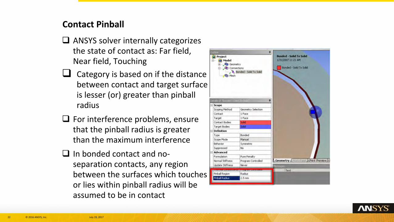
ANSYS solver internally categorizes the state of contact as: Far field, Near field, Touching
Category is based on if the distance between contact and target surface is lesser (or) greater than pinball radius
For interference problems, ensure that the pinball radius is greater than the maximum interference
In bonded contact and no-separation contacts, any region between the surfaces which touches or lies within pinball radius will be assumed to be in contact
Contact Pinball
23 © 2016 ANSYS, Inc. July 19, 2017
Contact Pinball - Notes
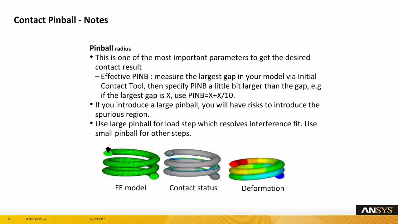
Pinball radius
• This is one of the most important parameters to get the desired contact result– Effective PINB : measure the largest gap in your model via Initial
Contact Tool, then specify PINB a little bit larger than the gap, e.gif the largest gap is X, use PINB=X+X/10.
• If you introduce a large pinball, you will have risks to introduce the spurious region.
• Use large pinball for load step which resolves interference fit. Use small pinball for other steps.
FE model Contact status Deformation
24 © 2016 ANSYS, Inc. July 19, 2017
Contact Pinball - Notes
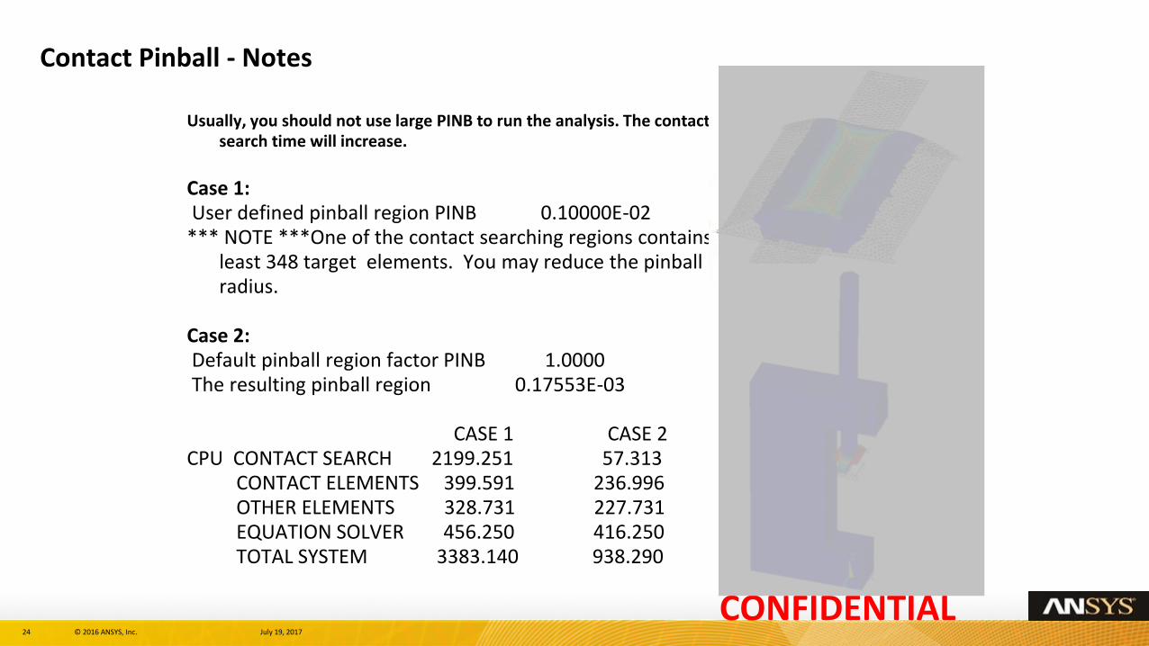
Usually, you should not use large PINB to run the analysis. The contact search time will increase.
Case 1: User defined pinball region PINB 0.10000E-02
*** NOTE ***One of the contact searching regions contains least 348 target elements. You may reduce the pinball radius.
Case 2: Default pinball region factor PINB 1.0000 The resulting pinball region 0.17553E-03
CASE 1 CASE 2CPU CONTACT SEARCH 2199.251 57.313
CONTACT ELEMENTS 399.591 236.996 OTHER ELEMENTS 328.731 227.731EQUATION SOLVER 456.250 416.250TOTAL SYSTEM 3383.140 938.290
CONFIDENTIAL
25 © 2016 ANSYS, Inc. July 19, 2017
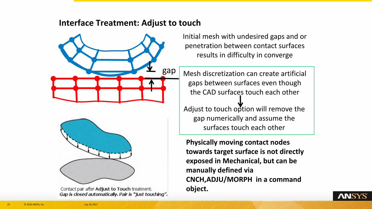
Interface Treatment: Adjust to touch
Initial mesh with undesired gaps and or penetration between contact surfaces
results in difficulty in converge
Mesh discretization can create artificial gaps between surfaces even though the CAD surfaces touch each other
Adjust to touch option will remove the gap numerically and assume the
surfaces touch each other
gap
Physically moving contact nodes towards target surface is not directly exposed in Mechanical, but can be manually defined via CNCH,ADJU/MORPH in a command object.
26 © 2016 ANSYS, Inc. July 19, 2017
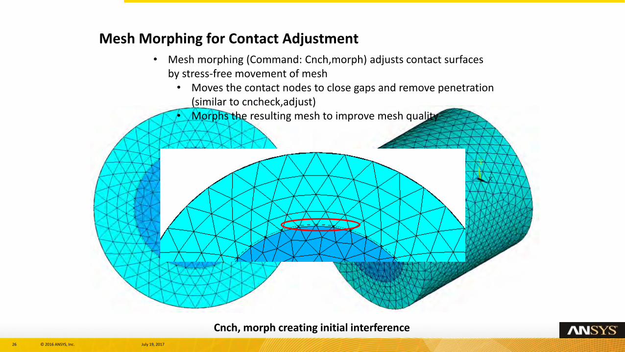
Cnch, morph creating initial interference
Mesh Morphing for Contact Adjustment
• Mesh morphing (Command: Cnch,morph) adjusts contact surfaces by stress-free movement of mesh• Moves the contact nodes to close gaps and remove penetration
(similar to cncheck,adjust)• Morphs the resulting mesh to improve mesh quality
27 © 2016 ANSYS, Inc. July 19, 2017
Modeling Interference Fit – Three Options
Contact surface offset (CNOF) as a function of time via tabular input• Use tabular input to specify a table in which the magnitude of CNOF is ramped down from the
possible maximum values of interference to zero over time.
• For Arbitrary interface with varying contact normal
Automatic interference fit method• The program automatically ramps the initial penetration down to zero over time along the true
contact normal direction.
• For near flat interface
User-defined contact surface normal• The automatically ramps the initial penetration down to zero over time along the user-defined shift
direction.
• For curve interface
Tip:
In some interference fit applications, the reactions calculated via contact element option may
differ from those calculated via underlying elements. In such scenarios, the underlying element
approach is more accurate. Try tightening the force tolerance (CNVTOL,F command)
to improve the contact element reaction calculations.
28 © 2016 ANSYS, Inc. July 19, 2017
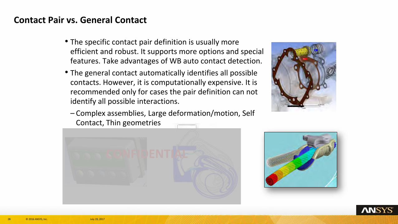
Contact Pair vs. General Contact
• The specific contact pair definition is usually more efficient and robust. It supports more options and special features. Take advantages of WB auto contact detection.
• The general contact automatically identifies all possible contacts. However, it is computationally expensive. It is recommended only for cases the pair definition can not identify all possible interactions.
– Complex assemblies, Large deformation/motion, Self Contact, Thin geometries
CONFIDENTIAL
29 © 2016 ANSYS, Inc. July 19, 2017
Section 3 : Dealing With Non Convergence
30 © 2016 ANSYS, Inc. July 19, 2017
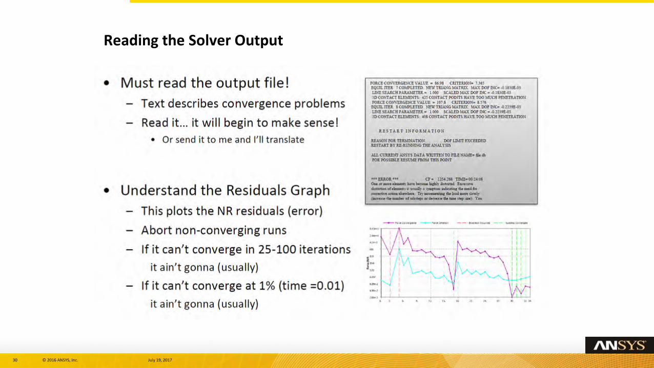
Reading the Solver Output
31 © 2016 ANSYS, Inc. July 19, 2017
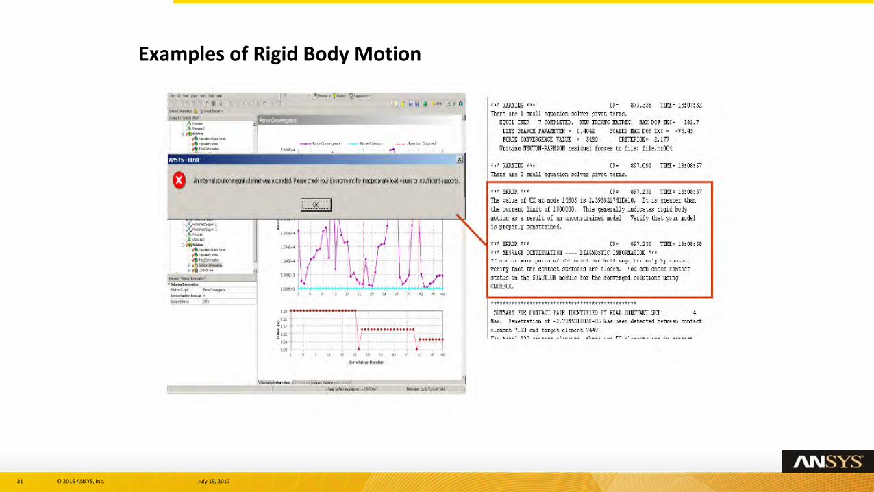
Examples of Rigid Body Motion
32 © 2016 ANSYS, Inc. July 19, 2017
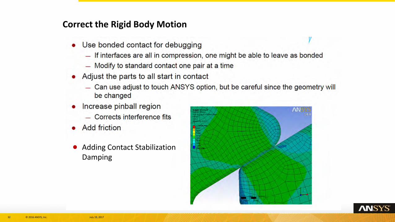
Correct the Rigid Body Motion
Adding Contact Stabilization Damping
33 © 2016 ANSYS, Inc. July 19, 2017
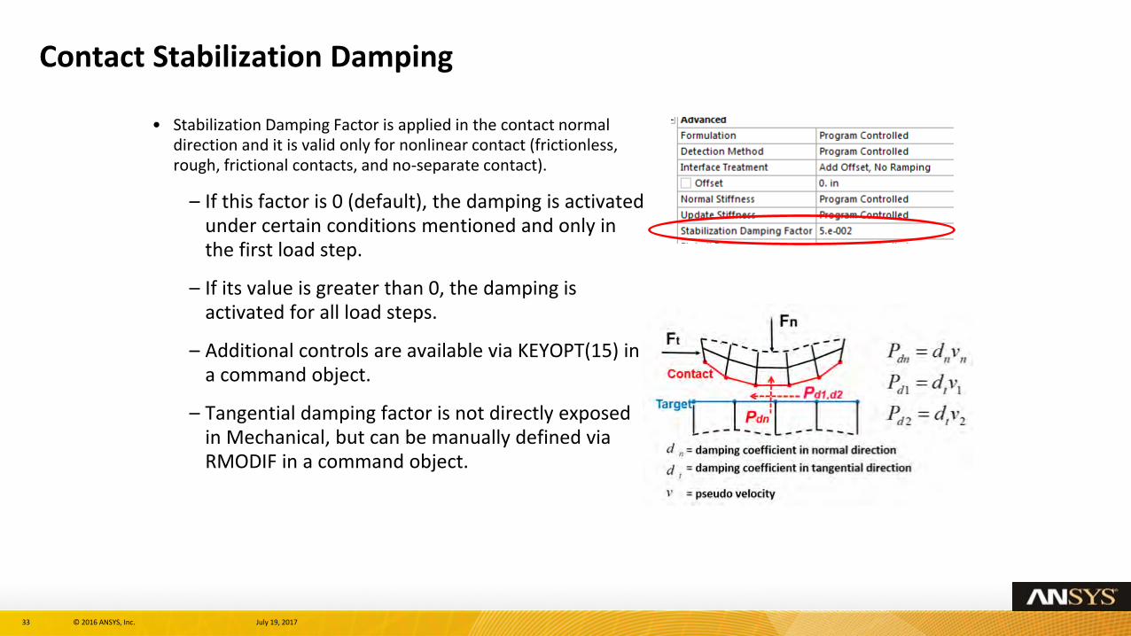
Contact Stabilization Damping
• Stabilization Damping Factor is applied in the contact normal direction and it is valid only for nonlinear contact (frictionless, rough, frictional contacts, and no-separate contact).
– If this factor is 0 (default), the damping is activated under certain conditions mentioned and only in the first load step.
– If its value is greater than 0, the damping is activated for all load steps.
– Additional controls are available via KEYOPT(15) in a command object.
– Tangential damping factor is not directly exposed in Mechanical, but can be manually defined via RMODIF in a command object.
34 © 2016 ANSYS, Inc. July 19, 2017
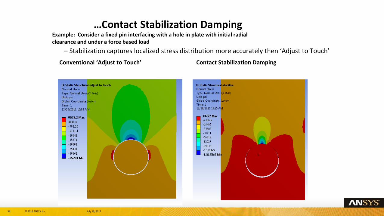
…Contact Stabilization Damping Example: Consider a fixed pin interfacing with a hole in plate with initial radialclearance and under a force based load
– Stabilization captures localized stress distribution more accurately then ‘Adjust to Touch’
Conventional ‘Adjust to Touch’ Contact Stabilization Damping
35 © 2016 ANSYS, Inc. July 19, 2017
Debug strategies: Overconstraints
Overconstrained model
•Overconstraints are indicated by the presence of zero pivot warnings. It often results in very large residual force (orders of magnitude larger than a typically applied force) followed by very easy convergence.
• First check potential overconstraints via Contact Tool
Tips for manually removing overconstraints
•Remove overlapped pairs
•Merge pairs
• Flip contact and target surfaces
•Add multiple layers
36 © 2016 ANSYS, Inc. July 19, 201736
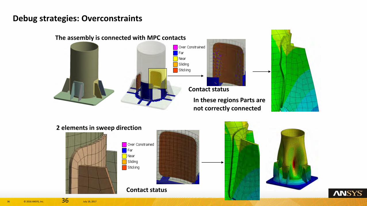
The assembly is connected with MPC contacts
In these regions Parts are not correctly connected
Contact status
2 elements in sweep direction
Contact status
Debug strategies: Overconstraints
37 © 2016 ANSYS, Inc. July 19, 2017
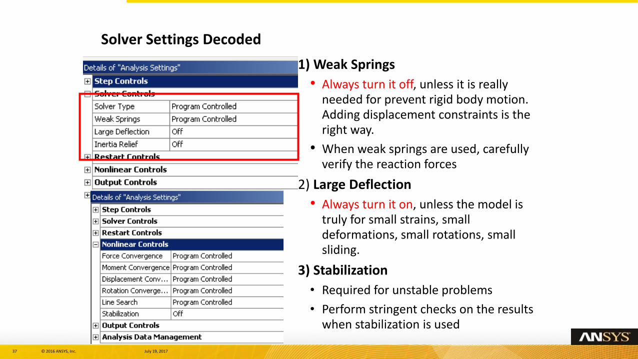
Solver Settings Decoded
1) Weak Springs
• Always turn it off, unless it is really needed for prevent rigid body motion. Adding displacement constraints is the right way.
• When weak springs are used, carefully verify the reaction forces
2) Large Deflection
• Always turn it on, unless the model is truly for small strains, small deformations, small rotations, small sliding.
3) Stabilization
• Required for unstable problems
• Perform stringent checks on the results when stabilization is used
F
38 © 2016 ANSYS, Inc. July 19, 2017
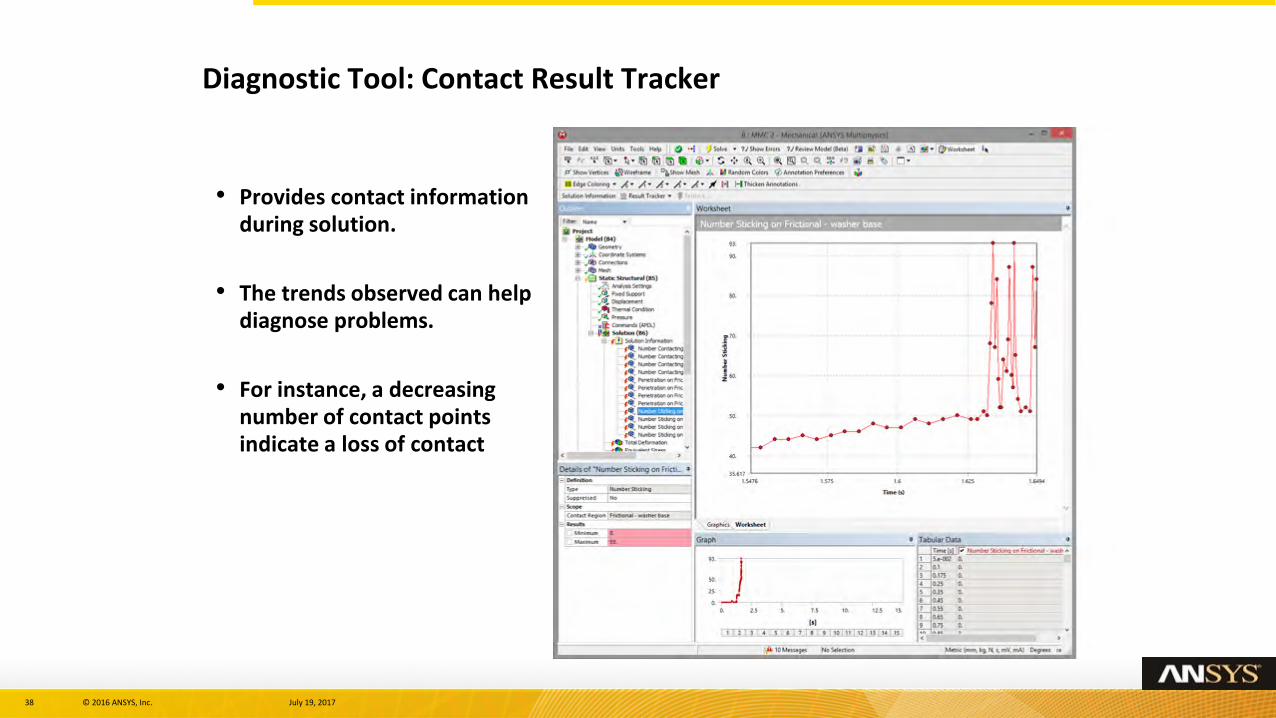
• Provides contact information during solution.
• The trends observed can help diagnose problems.
• For instance, a decreasing number of contact points indicate a loss of contact
Diagnostic Tool: Contact Result Tracker
39 © 2016 ANSYS, Inc. July 19, 2017
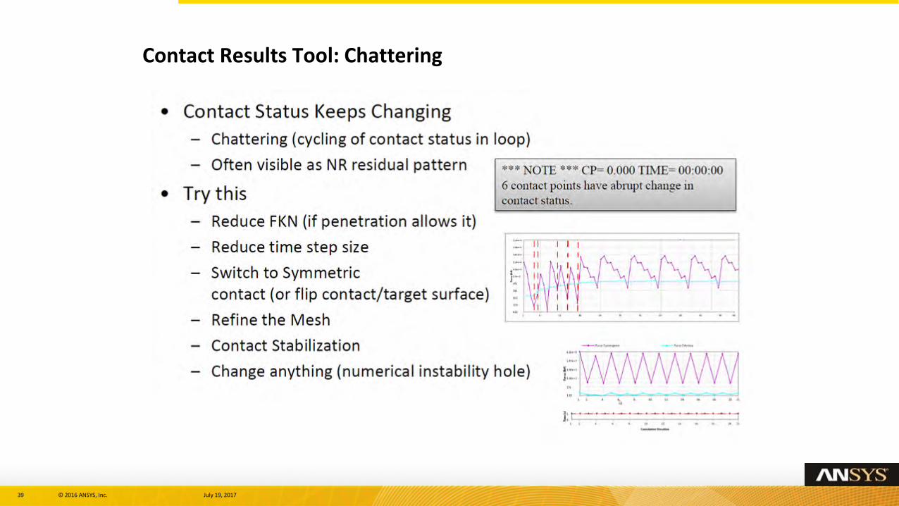
Contact Results Tool: Chattering
40 © 2016 ANSYS, Inc. July 19, 2017
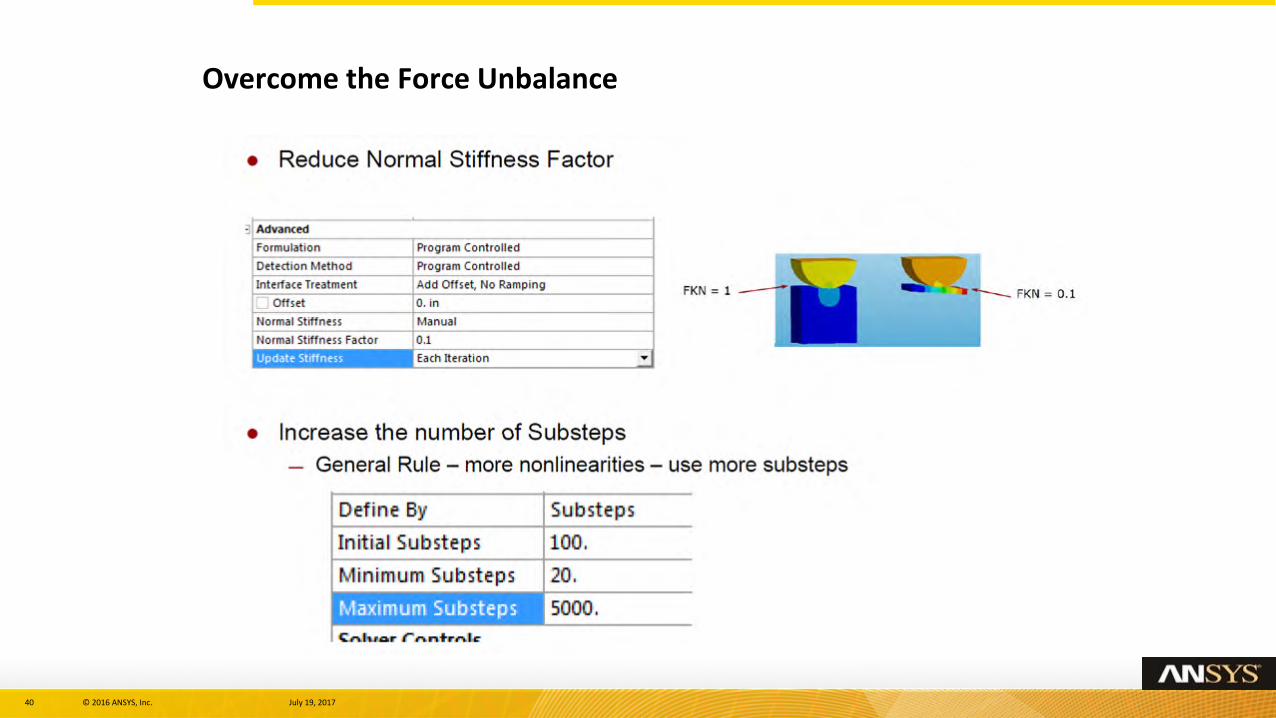
Overcome the Force Unbalance
41 © 2016 ANSYS, Inc. July 19, 2017
Overcome the Force Unbalance
42 © 2016 ANSYS, Inc. July 19, 2017
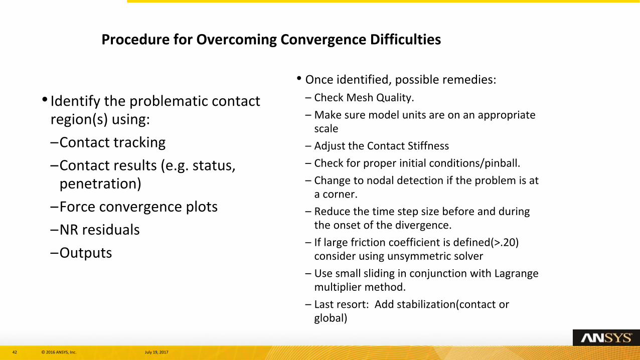
• Identify the problematic contact region(s) using:
–Contact tracking
–Contact results (e.g. status, penetration)
–Force convergence plots
–NR residuals
–Outputs
• Once identified, possible remedies:
– Check Mesh Quality.
– Make sure model units are on an appropriate scale
– Adjust the Contact Stiffness
– Check for proper initial conditions/pinball.
– Change to nodal detection if the problem is at a corner.
– Reduce the time step size before and during the onset of the divergence.
– If large friction coefficient is defined(>.20) consider using unsymmetric solver
– Use small sliding in conjunction with Lagrange multiplier method.
– Last resort: Add stabilization(contact or global)
Procedure for Overcoming Convergence Difficulties
43 © 2016 ANSYS, Inc. July 19, 2017
Debug strategies: Check non contact-related issues
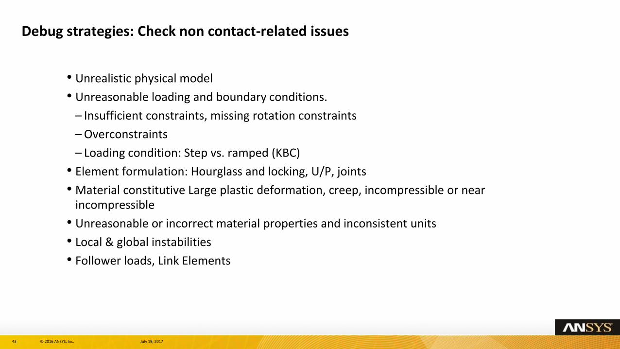
• Unrealistic physical model
• Unreasonable loading and boundary conditions.
– Insufficient constraints, missing rotation constraints
– Overconstraints
– Loading condition: Step vs. ramped (KBC)
• Element formulation: Hourglass and locking, U/P, joints
• Material constitutive Large plastic deformation, creep, incompressible or near incompressible
• Unreasonable or incorrect material properties and inconsistent units
• Local & global instabilities
• Follower loads, Link Elements
44 © 2016 ANSYS, Inc. July 19, 2017
Debug strategies: Other Attempts
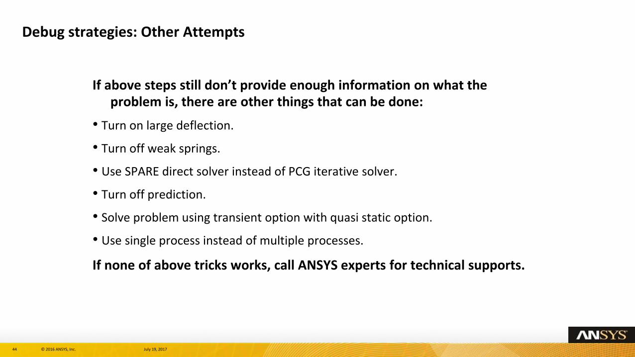
If above steps still don’t provide enough information on what the problem is, there are other things that can be done:
• Turn on large deflection.
• Turn off weak springs.
• Use SPARE direct solver instead of PCG iterative solver.
• Turn off prediction.
• Solve problem using transient option with quasi static option.
• Use single process instead of multiple processes.
If none of above tricks works, call ANSYS experts for technical supports.