Embed Size (px)
Citation preview

Best Practice in Industrial Data Communications

WHO ARE WE? IDC Technologies is internationally acknowledged as the premier provider of practical, technical training for engineers and technicians. We specialize in the fields of electrical systems, industrial data communications, telecommunications, automation and control, mechanical engineering, chemical and civil engineering, and are continually adding to our portfolio of over 60 different workshops. Our instructors are highly respected in their fields of expertise and in the last ten years have trained over 200,000 engineers, scientists and technicians. With offices conveniently located worldwide, IDC Technologies has an enthusiastic team of professional engineers, technicians and support staff who are committed to providing the highest level of training and consultancy. TECHNICAL WORKSHOPS TRAINING THAT WORKS We deliver engineering and technology training that will maximize your business goals. In today’s competitive environment, you require training that will help you and your organization to achieve its goals and produce a large return on investment. With our ‘training that works’ objective you and your organization will:
• Get job-related skills that you need to achieve your business goals • Improve the operation and design of your equipment and plant • Improve your troubleshooting abilities • Sharpen your competitive edge • Boost morale and retain valuable staff • Save time and money
EXPERT INSTRUCTORS We search the world for good quality instructors who have three outstanding attributes:
1. Expert knowledge and experience – of the course topic 2. Superb training abilities – to ensure the know-how is transferred effectively and quickly to you in
a practical, hands-on way 3. Listening skills – they listen carefully to the needs of the participants and want to ensure that you
benefit from the experience. Each and every instructor is evaluated by the delegates and we assess the presentation after every class to ensure that the instructor stays on track in presenting outstanding courses. HANDS-ON APPROACH TO TRAINING All IDC Technologies workshops include practical, hands-on sessions where the delegates are given the opportunity to apply in practice the theory they have learnt. REFERENCE MATERIALS A fully illustrated workshop book with hundreds of pages of tables, charts, figures and handy hints, plus considerable reference material is provided FREE of charge to each delegate. ACCREDITATION AND CONTINUING EDUCATION Satisfactory completion of all IDC workshops satisfies the requirements of the International Association for Continuing Education and Training for the award of 1.4 Continuing Education Units. IDC workshops also satisfy criteria for Continuing Professional Development according to the requirements of the Institution of Electrical Engineers and Institution of Measurement and Control in the UK, Institution of Engineers in Australia, Institution of Engineers New Zealand, and others.
THIS BOOK WAS DEVELOPED BY IDC TECHNOLOGIES

CERTIFICATE OF ATTENDANCE Each delegate receives a Certificate of Attendance documenting their experience. 100% MONEY BACK GUARANTEE IDC Technologies’ engineers have put considerable time and experience into ensuring that you gain maximum value from each workshop. If by lunchtime on the first day you decide that the workshop is not appropriate for your requirements, please let us know so that we can arrange a 100% refund of your fee. ONSITE WORKSHOPS All IDC Technologies Training Workshops are available on an on-site basis, presented at the venue of your choice, saving delegates travel time and expenses, thus providing your company with even greater savings. OFFICE LOCATIONS
AUSTRALIA • CANADA • INDIA • IRELAND • MALAYSIA • NEW ZEALAND • POLAND • SINGAPORE • SOUTH AFRICA • UNITED KINGDOM • UNITED STATES
On-Site Training
All IDC Technologies Training Workshops are available on an on-site basis, presented at the venue of your choice, saving delegates travel time and expenses, thus providing your company with even
greater savings. For more information or a FREE detailed proposal contact Kevin Baker by e-mailing:
[email protected] www.idc-online.com
Visit our website for FREE Pocket Guides IDC Technologies produce a set of 6 Pocket Guides used by
thousands of engineers and technicians worldwide. Vol. 1 – ELECTRONICS Vol. 4 – INSTRUMENTATION Vol. 2 – ELECTRICAL Vol. 5 – FORMULAE & CONVERSIONS Vol. 3 – COMMUNICATIONS Vol. 6 – INDUSTRIAL AUTOMATION
To download a FREE copy of these internationally best selling pocket guides go to:
www.idc-online.com/downloads/
SAVE MORE THAN 50% OFF the per person
cost
CUSTOMISE the training to YOUR WORKPLACE!
Have the training delivered WHEN
AND WHERE you need it!

IDC TECHNOLOGIES
Worldwide Offices
AUSTRALIA Telephone: 1300 138 522 • Facsimile: 1300 138 533
West Coast Office
1031 Wellington Street, West Perth, WA 6005 PO Box 1093, West Perth, WA 6872
East Coast Office
PO Box 1750, North Sydney, NSW 2059
CANADA Toll Free Telephone: 1800 324 4244 • Toll Free Facsimile: 1800 434 4045
Suite 402, 814 Richards Street, Vancouver, NC V6B 3A7
INDIA Telephone : +91 444 208 9353
35 4th Street, Kumaran Colony, Vadapalani, Chennai 600026
IRELAND Telephone : +353 1 473 3190 • Facsimile: +353 1 473 3191
PO Box 8069, Shankill Co Dublin
MALAYSIA Telephone: +60 3 5192 3800 • Facsimile: +60 3 5192 3801
26 Jalan Kota Raja E27/E, Hicom Town Center Seksyen 27, 40400 Shah Alam, Selangor
NEW ZEALAND
Telephone: +64 9 263 4759 • Facsimile: +64 9 262 2304 Parkview Towers, 28 Davies Avenue, Manukau City
PO Box 76-142, Manukau City
POLAND Telephone: +48 12 6304 746 • Facsimile: +48 12 6304 750
ul. Krakowska 50, 30-083 Balice, Krakow
SINGAPORE Telephone: +65 6224 6298 • Facsimile: + 65 6224 7922
100 Eu Tong Sen Street, #04-11 Pearl’s Centre, Singapore 059812
SOUTH AFRICA Telephone: +27 87 751 4294 or +27 79 629 5706 • Facsimile: +27 11 312 2150
68 Pretorius Street, President Park, Midrand PO Box 389, Halfway House 1685
UNITED KINGDOM
Telephone: +44 20 8335 4014 • Facsimile: +44 20 8335 4120 Suite 18, Fitzroy House, Lynwood Drive, Worcester Park, Surrey KT4 7AT
UNITED STATES
Toll Free Telephone: 1800 324 4244 • Toll Free Facsimile: 1800 434 4045 7101 Highway 71 West #200, Austin TX 78735
Website: www.idc-online.com
Email: [email protected]

Presents
Best Practice in Industrial Data Communications
Revision 6
Website: www.idc-online.com E-mail: [email protected]

IDC Technologies Pty Ltd PO Box 1093, West Perth, Western Australia 6872 Offices in Australia, New Zealand, Singapore, United Kingdom, Ireland, Malaysia, Poland, United States of America, Canada, South Africa and India Copyright © IDC Technologies 2005. All rights reserved. First published 2005 All rights to this publication, associated software and workshop are reserved. No part of this publication may be reproduced, stored in a retrieval system or transmitted in any form or by any means electronic, mechanical, photocopying, recording or otherwise without the prior written permission of the publisher. All enquiries should be made to the publisher at the address above. Disclaimer Whilst all reasonable care has been taken to ensure that the descriptions, opinions, programs, listings, software and diagrams are accurate and workable, IDC Technologies do not accept any legal responsibility or liability to any person, organization or other entity for any direct loss, consequential loss or damage, however caused, that may be suffered as a result of the use of this publication or the associated workshop and software.
In case of any uncertainty, we recommend that you contact IDC Technologies for clarification or assistance.
Trademarks All logos and trademarks belong to, and are copyrighted to, their companies respectively. Acknowledgements IDC Technologies expresses its sincere thanks to all those engineers and technicians on our training workshops who freely made available their expertise in preparing this manual.
Contents 1 General Topics 1 1.1 Overview 1 1.2 OSI reference model 2 1.3 Systems engineering approach 8 1.4 State transition structure 10 1.5 Detailed design 11 1.6 Media 11 1.7 Physical connections 12 1.8 Protocols 13 1.9 Noise 15 1.10 Cable spacing 21 1.11 Ingress protection 25
2 Copper Cable 27 2.1 Cable characteristics 27 2.2 Cable selection 31 2.3 Coaxial cables 32 2.4 Twisted pair cable 35 2.5 Distribution/installation standards 40 2.6 Connector standards 42 2.7 Earthing/grounding 44 2.8 Termination 46 2.9 Transient protection 48
3 Fiber Optics 51 3.1 Introduction 51 3.2 Fiber–optic cable components 52 3.3 Fiber optic cable parameters 54 3.4 Types of optical fiber 55 3.5 Basic cable types 56 3.6 Connecting fibers 58 3.7 Splicing trays/organizers and termination cabinets 61 3.8 Troubleshooting 64
3.9 Fiber installation rules 65 3.10 Cleaning optical connectors 66 3.11 Locating broken fibers 67
4a RS-232 Overview 73 4a.1 RS-232 Interface standard (CCITT V.24 Interface standard) 73 4a.2 Half-duplex operation of the RS-232 interface 81 4a.3 Summary of RS-232 revisions 83 4a.4 Limitations 84
4b RS-232 Troubleshooting 85 4b.1 Introduction 85 4b.2 Typical approach 85 4b.3 Test equipment 87 4b.4 Typical RS-232 problems 89 4b.5 Summary of troubleshooting 94
5a RS-485 Overview 95 5a.1 The RS-485 interface standard 95
5b RS-485 Troubleshooting 101 5b.1 Introduction 101 5b.2 RS-485 vs. RS-422 102 5b.3 RS-485 installation 102 5b.4 Noise problems 104 5b.5 Test equipment 107 5b.6 Summary 110
6a Current loop and RS-485 Converters Overview 113 6a.1 The 20 mA current loop 113 6a.2 Serial interface converters 114
6b Current loop and EIA–485 Converters Troubleshooting 117
6b.1 Troubleshooting converters 117
7a TCP/IP Overview 119 7a.1 Introduction 119 7a.2 Internet layer protocols (packet transport) 121 7a.3 Host-to-host layer: end to end reliability 132
7b TCP/IP Troubleshooting 135 7b.1 Introduction 135 7b.2 Common problems 135 7b.3 Tools of the trade 135 7b.4 Typical network layer problems 136 7b.5 Transport layer problems 138
8a Modbus Overview 141 8a.1 General overview 141 8a.2 Modbus protocol structure 143 8a.3 Function codes 144
8b Modbus Troubleshooting 155 8b.1 Detailed troubleshooting 155 8b.2 Conclusion 155 8b.3 Detailed Troubleshooting 156
9 Fundamentals of DNP3 163 9.1 Fundamental concepts 163 9.2 Understanding the DNP3 message structure 167 9.3 Physical layer 169 9.4 Data link layer 172 9.5 Transport layer (pseudo-transport) 185 9.6 Application layer message handling 187 9.7 Application layer message functions 199
10 Fundamentals of IEC 60870-5 213 10.1 The IEC 60870-5 standard 213 10.2 Protocol architecture 217 10.3 Physical layer 220 10.4 Datalink layer 222 10.5 Application layer 236 10.6 Information elements 248
11a Industrial Ethernet Overview 251 11a.1 Introduction 251 11a.2 10 Mbps Ethernet 252 11a.3 100 Mbps Ethernet 265 11a.4 Gigabit Ethernet 268 11a.5 Industrial Ethernet 271
11b Industrial Ethernet Troubleshooting 277 11b.1 Introduction 277 11b.2 Common problems and faults 277 11b.3 Tools of the trade 278 11b.4 Problems and solutions 280 11b.5 Troubleshooting switched networks 291 11b.6 Troubleshooting fast Ethernet 292 11b.7 Troubleshooting Gigabit Ethernet 292
12a AS-interface (AS-i) Overview 293 12a.1 Introduction 293 12a.2 Layer 1 – The physical layer 294 12a.3 Layer 2 – the data link layer 296 12a.4 Operating characteristics 298
12b AS-i Troubleshooting 299 12b.1 Introduction 299 12b.2 Tools of the trade 299
13a DeviceNet Overview 301 13a.1 Introduction 301 13a.2 Physical layer 302 13a.3 Connectors 303 13a.4 Cable budgets 306 13a.5 Device taps 306 13a.6 Cable description 310 13a.7 Network power 312 13a.8 System grounding 315 13a.9 Signaling 316 13a.10 Data link layer 317 13a.11 The application layer 319
13b DeviceNet Troubleshooting 321 13b.1 Introduction 321 13b.2 Tools of the trade 321 13b.3 Fault finding procedures 324
14a Profibus PA/DP/FMS Overview 329 14a.1 Introduction 329 14a.2 ProfiBus protocol stack 329 14a.3 The ProfiBus communication model 338 14a.4 Relationship between application process and communication 338 14a.5 Communication objects 339 14a.6 Performance 340 14a.7 System operation 341
14b Profibus Troubleshooting 345 14b.1 Introduction 345 14b.2 Troubleshooting tools 345 14b.3 Tips 348
15a Profibus PA/DP/FMS Overview 351 15a.1 Introduction to Foundation Fieldbus 351 15a.2 The physical layer and wiring rules 352
15a.3 The data link layer 355 15a.4 The application layer 355 15a.5 The user layer 356 15a.6 Error detection and diagnostics 356 15a.7 High Speed Ethernet (HSE) 358 15a.8 Good wiring and installation practice 358
15b Foundation Fieldbus Troubleshooting 361 15b.1 Introduction 361 15b.2 Power problems 362 15b.3 Communication problems 363 15b.4 Foundation Fieldbus test equipment 365
16a Modbus Plus Protocol Overview 367 16a.1 General overview 367
16b Modbus Plus Troubleshooting 371 16b.1 Common problems and faults 371 16b.2 Description of tools used 372 16b.3 Detailed troubleshooting 372
17a Data Highway Plus/DH485 Overview 377 17a.1 Allen Bradley Data Highway (Plus) protocol 377
17b Data Highway Plus/DH485 Troubleshooting 387 17b.1 Introduction 387 17b.2 Data Highway Plus wiring troubleshooting 387 17b.3 Data Highway Plus network diagnostics 388
18a HART Overview 391 18a.1 Introduction to HART and smart instrumentation 391 18a.2 HART protocol 392 18a.3 Physical layer 393 18a.4 Data link layer 395
18a.5 Application layer 396
18b HART Troubleshooting 399 18b.1 Troubleshooting HART systems 399
19 Wireless Technologies 401 19.1 Satellite systems 401 19.2 Wireless LANs (WLANs) 408 19.3 Radio and wireless communications 414
20 System Design Methodology 433 20.1 Introduction 433 20.2 Point to point links 435 20.3 Networked systems 438
21 Installation, Commissioning, Troubleshooting 443 21.1 Introduction 443 21.2 Methodology 443 21.3 Common problems 444

1
General Topics
1.1 Overview This manual can be divided into several distinct sections:
1.1.1 Introduction Chapter 1: This introductory chapter deals with general topics such as the OSI model, systems engineering concepts, physical (layer 1) connections, protocols, and noise and ingress protection.
1.1.2 Media Chapters 2 and 3 deal with media – specifically conductive media viz. copper (coax, UTP, STP) and fiber.
1.1.3 Physical layer standards Chapters 4–6 (inclusive), cover RS-232, RS-485, and 4-20 mA. Note: Throughout this manual we will refer to RS-232, RS-422 and RS-485. One is often criticized for using these terms of reference, since in reality they are obsolete. However, if we briefly examine the history of the organization that defined these standards, it is not difficult to see why they are still in use today, and will probably continue as such.
The Electronics Industry Association (EIA) of America defined the common serial interface RS-232. ‘RS’ stands for ‘recommended standard’, and the number (suffix -232) refers to the interface specification of the physical device. The EIA has since established many standards and amassed a library of white papers on various implementations of them. So to keep track of them all it made sense to change the prefix to EIA. (It is interesting to note that most of the white papers are NOT free).
The Telecommunications Industry Association (TIA) was formed in 1988, by merging the telecommunications arm of the EIA and the United States Telecommunications
2 Best Practice in Industrial Data Communications
Suppliers Association. The prefix changed again to EIA/TIA-232, (along with all the other serial implementations of course). So now we have TIA-232, TIA-485 etc.
It should also be noted that the TIA is a member of the Electronics Industries Alliance (EIA). This alliance is made up of several trade organizations (including the CEA, ECA, GEIA...) that represent the interests of manufacturers of electronics-related products. Now when someone refers to ‘EIA’ they are talking about the Alliance, not the Association!
If we still use the terms EIA-232, EIA-422 etc, then they are just as equally obsolete as the ‘RS’ equivalents. However, when they are referred to as TIA standards some people might give you a quizzical look and ask you to explain yourself... So to cut a long story short, one says ‘RS-xxx’ -- and the penny drops. ‘RS’ has become more or less a de facto approach, as a search on the Internet will testify.
Copies of the relevant standards are available from Global Engineering documents, the official suppliers of EIA documents. A brief perusal of their website (http://global.ihs.com) will reveal the name changes over time, since names were not changed retroactively. The latest ‘232’ revision refers to TIA-232, but earlier revisions and other related documents still refer to TIA/EIA-232, EIA-232 and RS-232.
1.1.4 Industrial protocols Chapters 7–10 (inclusive), chapters deal with a few well-known industrial protocols such as TCP/IP, Modbus, DNP3 and IEC 60870.
1.1.5 Industrial networks Chapters 11–18 (inclusive), deal with some popular industrial networks (both old and new) such as Industrial Ethernet, AS-i, DeviceNet, Profibus, Foundation Fieldbus, Modbus Plus, Data Highway Plus and HART. Although the topic of troubleshooting only follows towards the end of the workshop, each chapter has been divided into an A and a B section, where the A section deals with the operation of the system and the B section deals with troubleshooting the same system. This has been done for ease of reference.
1.1.6 Other technologies Chapter 19 deals with several wireless technologies, including VSAT, IEEE 802.11 and wireless point-to-point.
1.1.7 Selection methodology Chapter 20 covers the appropriate steps to be taken in choosing the components for an industrial data communications system.
1.1.8 Installation, commissioning, troubleshooting Chapter 21 covers recommended practice in installing, commissioning and troubleshooting industrial data communications systems.
1.2 OSI reference model Faced with the proliferation of closed network systems, the International Organization for Standardization (ISO) defined a ‘Reference Model for Communication between Open Systems’ in 1978. This has become known as the Open Systems Interconnection Reference model, or simply as the OSI model (ISO7498). The OSI model is essentially a
General Topics 3
data communications management structure, which breaks data communications down into a manageable hierarchy of seven layers.
Each layer has a defined purpose and interfaces with the layers above it and below it. By laying down standards for each layer, some flexibility is allowed so that the system designers can develop protocols for each layer independent of each other. By conforming to the OSI standards, a system is able to communicate with any other compliant system, anywhere in the world.
At the outset it should be realized that the OSI reference model is not a protocol or set of rules for how a protocol should be written but rather an overall framework in which to define protocols. The OSI model framework specifically and clearly defines the functions or services that have to be provided at each of the seven layers (or levels).
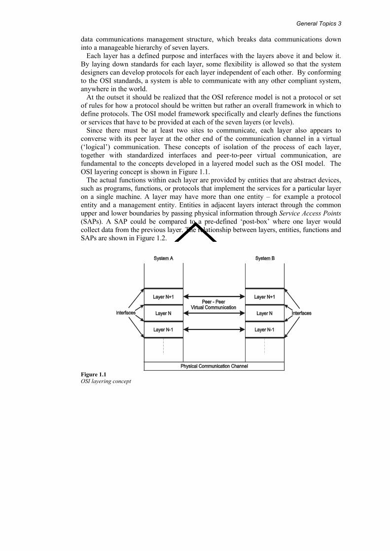
Since there must be at least two sites to communicate, each layer also appears to converse with its peer layer at the other end of the communication channel in a virtual (‘logical’) communication. These concepts of isolation of the process of each layer, together with standardized interfaces and peer-to-peer virtual communication, are fundamental to the concepts developed in a layered model such as the OSI model. The OSI layering concept is shown in Figure 1.1.
The actual functions within each layer are provided by entities that are abstract devices, such as programs, functions, or protocols that implement the services for a particular layer on a single machine. A layer may have more than one entity – for example a protocol entity and a management entity. Entities in adjacent layers interact through the common upper and lower boundaries by passing physical information through Service Access Points (SAPs). A SAP could be compared to a pre-defined ‘post-box’ where one layer would collect data from the previous layer. The relationship between layers, entities, functions and SAPs are shown in Figure 1.2.
Figure 1.1 OSI layering concept
4 Best Practice in Industrial Data Communications
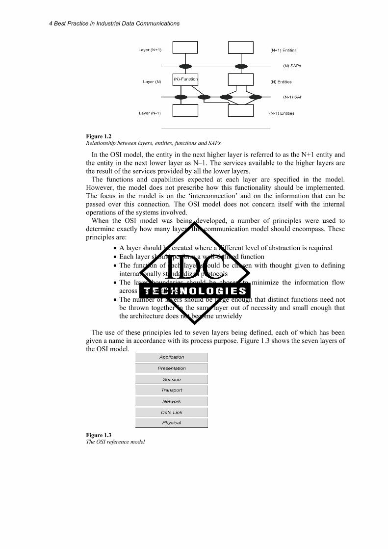
Figure 1.2 Relationship between layers, entities, functions and SAPs
In the OSI model, the entity in the next higher layer is referred to as the N+1 entity and the entity in the next lower layer as N–1. The services available to the higher layers are the result of the services provided by all the lower layers.
The functions and capabilities expected at each layer are specified in the model. However, the model does not prescribe how this functionality should be implemented. The focus in the model is on the ‘interconnection’ and on the information that can be passed over this connection. The OSI model does not concern itself with the internal operations of the systems involved.
When the OSI model was being developed, a number of principles were used to determine exactly how many layers this communication model should encompass. These principles are:
• A layer should be created where a different level of abstraction is required • Each layer should perform a well-defined function • The function of each layer should be chosen with thought given to defining
internationally standardized protocols • The layer boundaries should be chosen to minimize the information flow
across the boundaries • The number of layers should be large enough that distinct functions need not
be thrown together in the same layer out of necessity and small enough that the architecture does not become unwieldy
The use of these principles led to seven layers being defined, each of which has been
given a name in accordance with its process purpose. Figure 1.3 shows the seven layers of the OSI model.
Figure 1.3 The OSI reference model
General Topics 5
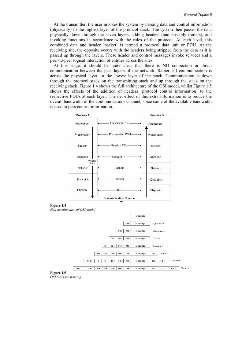
At the transmitter, the user invokes the system by passing data and control information (physically) to the highest layer of the protocol stack. The system then passes the data physically down through the seven layers, adding headers (and possibly trailers), and invoking functions in accordance with the rules of the protocol. At each level, this combined data and header ‘packet’ is termed a protocol data unit or PDU. At the receiving site, the opposite occurs with the headers being stripped from the data as it is passed up through the layers. These header and control messages invoke services and a peer-to-peer logical interaction of entities across the sites.
At this stage, it should be quite clear that there is NO connection or direct communication between the peer layers of the network. Rather, all communication is across the physical layer, or the lowest layer of the stack. Communication is down through the protocol stack on the transmitting stack and up through the stack on the receiving stack. Figure 1.4 shows the full architecture of the OSI model, whilst Figure 1.5 shows the effects of the addition of headers (protocol control information) to the respective PDUs at each layer. The net effect of this extra information is to reduce the overall bandwidth of the communications channel, since some of the available bandwidth is used to pass control information.
Figure 1.4 Full architecture of OSI model
Figure 1.5 OSI message passing
6 Best Practice in Industrial Data Communications
1.2.1 OSI layer services Briefly, the services provided at each layer of the stack are:
• Application (layer 7) – the provision of network services to the user’s application programs (clients, servers etc.). Note: the user’s actual application programs do NOT reside here
• Presentation (layer 6) – maps the data representations into an external data format that will enable correct interpretation of the information on receipt. The mapping can also possibly include encryption and/or compression of data
• Session (layer 5) – control of the communications between the users. This includes the grouping together of messages and the coordination of data transfer between grouped layers. It also effects checkpoints for (transparent) recovery of aborted sessions
• Transport (layer 4) – the management of the communications between the two end systems
• Network (layer 3) – responsible for the control of the communications network. Functions include routing of data, network addressing, fragmentation of large packets, congestion and flow control
• Data Link (layer 2) – responsible for sending a frame of data from one system to another. Attempts to ensure that errors in the received bit stream are not passed up into the rest of the protocol stack. Error correction and detection techniques are used here
• Physical (layer 1) – Defines the electrical and mechanical connections at the physical level, or the communication channel itself. Functional responsibilities include modulation, multiplexing and signal generation. Note that the Physical layer defines, but does NOT include the medium. This is located below the physical layer and is sometimes referred to as layer 0
A more specific discussion of each layer is now presented.
Application layer
The application layer is the topmost layer in the OSI model. This layer is responsible for giving applications access to the network. Examples of application-layer tasks include file transfer, electronic mail services, and network management. Application-layer services are more varied than the services in lower layers, because the entire range of application and task possibilities is available here. To accomplish its tasks, the application layer passes program requests and data to the presentation layer, which is responsible for encoding the application layer’s data in the appropriate form.
Presentation layer
The presentation layer is responsible for presenting information in a manner suitable for the applications or users dealing with the information. Functions, such as data conversion from EBCDIC to ASCII (or vice versa), use of special graphics or character sets, data compression or expansion, and data encryption or decryption are carried out at this layer. The presentation layer provides services for the application layer above it, and uses the session layer below it. In practice, the presentation layer rarely appears in pure form, and is the least well defined of the OSI layers. Application- or session-layer programs will often encompass some or all of the presentation layer functions.
General Topics 7
Session layer
The session layer is responsible for synchronizing and sequencing the dialogue and packets in a network connection. This layer is also responsible for making sure that the connection is maintained until the transmission is complete, and ensuring that appropriate security measures are taken during a ‘session’ (that is, a connection). The session layer is used by the presentation layer above it, and uses the transport layer below it.
Transport layer
In the OSI model the transport layer is responsible for providing data transfer at an agreed-upon level of quality, such as at specified transmission speeds and error rates. To ensure delivery, outgoing packets are assigned numbers in sequence. The numbers are included in the packets that are transmitted by lower layers. The transport layer at the receiving end checks the packet numbers to make sure all have been delivered and to put the packet contents into the proper sequence for the recipient. The transport layer provides services for the session layer above it, and uses the network layer below it to find a route between source and destination. In many ways the transport layer is crucial because it sits between the upper layers (which are strongly application-dependent) and the lower ones (which are network-based).
The layers below the transport layer are collectively known as the subnet layers. Depending on how well (or not) they perform their function, the transport layer has to interfere less (or more) in order to maintain a reliable connection.
Network layer
The network layer is the third lowest layer, or the uppermost subnet layer. It is responsible for the following tasks:
• Determining addresses or translating from hardware to network addresses. These addresses may be on a local network or they may refer to networks located elsewhere on an internetwork. One of the functions of the network layer is, in fact, to provide capabilities needed to communicate on an internetwork
• Finding a route between a source and a destination node or between two intermediate devices
• Establishing and maintaining a logical connection between these two nodes, to establish either a connectionless or a connection-oriented communication. The data is processed and transmitted using the data-link layer below the network layer. Responsibility for guaranteeing proper delivery of the packets lies with the transport layer, which uses network-layer services
• Fragmentation of large packets of data into frames which are small enough to be transmitted by the underlying data link layer. The corresponding network layer at the receiving node undertakes re-assembly of the packet
Data link layer
The data link layer is responsible for creating, transmitting, and receiving data packets. It provides services for the various protocols at the network layer, and uses the physical layer to transmit or receive material. The data link layer creates packets appropriate for the network architecture being used. Requests and data from the network layer are part of the data in these packets (or frames, as they are often called at this layer). These packets are passed down to the physical layer and from there the data is transmitted to the
8 Best Practice in Industrial Data Communications
physical layer on the destination machine. Network architectures (such as Ethernet, ARCnet, token ring, and FDDI) encompass the data-link and physical layers, which is why these architectures support services at the data-link level. These architectures also represent the most common protocols used at the data-link level.
The IEEE802.x networking working groups have refined the data-link layer into two sub-layers: the logical-link control (LLC) sub-layer at the top and the media-access control (MAC) sub-layer at the bottom. The LLC sub-layer must provide an interface for the network layer protocols, and control the logical communication with its peer at the receiving side. The MAC sublayer must provide access to a particular physical encoding and transport scheme.
Physical layer
The physical layer is the lowest layer in the OSI reference model. This layer gets data packets from the data link layer above it, and converts the contents of these packets into a series of electrical signals that represent 0 and 1 values in a digital transmission. These signals are sent across a transmission medium to the physical layer at the receiving end. At the destination, the physical layer converts the electrical signals into a series of bit values. These values are grouped into packets and passed up to the data-link layer.
The mechanical and electrical properties of the transmission medium are defined at this level. These include the following:
• The type of cable and connectors used. A cable may be coaxial, twisted-pair, or fiber optic. The types of connectors depend on the type of cable.
• The pin assignments for the cable and connectors. Pin assignments depend on the type of cable and also on the network architecture being used.
• The format for the electrical signals. The encoding scheme used to signal 0 and 1 values in a digital transmission or particular values in an analog transmission depend on the network architecture being used. Most networks use digital signalling, and most use some form of Manchester encoding for the signal.
1.3 Systems engineering approach
1.3.1 System specifications Systems engineering, especially in a military context, is a fully-fledged subject and proper treatment thereof will warrant a two-day workshop on its own. However, the basic principles of systems engineering can be applied very advantageously throughout the life cycle of any project, and hence we will briefly look at the concepts. The project, in the context of this workshop, would involve the planning, installation, commissioning and ongoing maintenance of some sort of industrial data communications system.
The question is: what is a system, where does it start and where does it end? The answer is a bit ambiguous – it depends where the designer draws the boundaries. For example; the engine of a motor vehicle, excluding gearbox, radiator, battery and engine mounts, but including fuel injection system, could be seen as a system in its own right. On the other hand, the car in its entirety could be seen as a system, and the engine one of its subsystems. Other subsystems could include the gearbox, drive train, electrical system, etc. In similar fashion a SCADA system integrator could view the entire product as the ‘system’ with, for example, the RTUs as subsystems, whereas for a hardware developer the RTU could be viewed as a ‘system’ in its own right.
General Topics 9
The point of departure should be the physical, mechanical and electrical environment in which the system operates. For a car engine this could include the dimensions of the engine compartment, minimum and maximum ambient temperatures and levels of humidity. An engine operating in Alaska in mid-winter faces different problems than its counterpart operating in Saudi Arabia.
In similar fashion an RTU developer or someone contemplating an RTU installation should consider:
• Minimum and maximum temperatures • Vibration • Humidity • Mounting constraints • IP rating requirements • Power supply requirements (voltage levels, tolerances, current consumption,
power backup and redundancy, etc) These should all be included in the specifications. Let is return to the engine. There are
five attributes necessary to fully describe it, but we will initially look at the first three attributes namely inputs, outputs and functions.
Inputs
What goes ‘into’ the system? Inputs would include fuel from the fuel pump, air input from the air filter, cold-water input from the radiator and electrical power from the battery. For each input, the mechanical, electrical and other details, as required, must be stated. For example, for the electrical inputs of the engine, the mechanical details of the +12 V and ground terminals must be given, as well as the voltage and current limits.
For an RTU the inputs could include: • Digital inputs (e.g. contact closures) • Analog inputs (e.g. 4-20 mA) • Communication input (RS-232) • Power (e.g. 12 Vdc at 100 mA)
Specifications should include all relevant electrical and mechanical considerations
including connector types, pin allocations, minimum and maximum currents, minimum and maximum voltage levels, maximum operating speeds, and any transient protection.
Stated in general; in the mathematical equation y = f (x), where x would be the input.
Outputs
What comes ‘out of’ the system? Engine outputs would include torque output to the gearbox, hot water to the radiator and exhaust gases to the exhaust system. For each output, the exact detail (including flange dimensions, bolt sizes, etc) has to be stated. The reason for this is simple. Each output of the engine has to mate exactly with the corresponding input of the associated auxiliary subsystem. Unless the two mating entities are absolutely complementary, dimensionally and otherwise, there will be a problem.
For an RTU the outputs could include: • Relay outputs • Open collector transistor outputs
Specifications should include maximum voltages and currents as well as maximum operating speeds, relay contact lifetime and transient protection. Stated in general; in the mathematical equation y = f (x), y (the output) occurs as a result of x, the input.
10 Best Practice in Industrial Data Communications
Functions
What does the system (viewed as a ‘black box’) do? The functions are built into the system black box. They convert the input(s) to the output(s) according to some built-in transfer function(s). The system can be seen as having a singular function with several sub-functions, or as simply having several separate functions. The overall function of the engine would be to convert fuel plus air into energy. Its main sub-function would be to convert the fuel plus air into torque to drive the car, another sub-function could be to provide electrical energy to the battery. In the mathematical equation above, this refers to the f ( ) part, in other words it takes ‘x’ and does something to it in order to produce ‘y’.
The three items mentioned so far describes the behavior of the system in terms of ‘what’ it has to do, but not ‘how’. It has, in other words, not described a specific implementation, but just a functional specification. Once this has been documented, reviewed (several times!) and ratified, the solution can be designed.
The full (detailed) specification has to include the ‘how’. For this, two additional descriptions are necessary. They are the structure of elements and couplings, and the state transition diagram.
Structure of elements and couplings
It is also referred to as the EC diagram. This refers to all the ‘building blocks’ of the system and their interrelationship, but does not elucidate the way they operate. In a car engine this would show the engine block, pistons, connecting rods, crankshaft, etc, and the way they are attached to each other.
For an RTU this would include a full electronic circuit diagram as well as a component placement diagram.
1.4 State transition structure This is also referred to as the ST diagram. This is the ‘timing diagram’ of the system. It explains, preferably in diagram form (e.g. flowchart), how all the building blocks interact. For the engine, it would show the combustion cycle of the engine, plus the firing sequence of the spark plugs etc.
For an RTU this would be an explanation of the system operation by means of a flow chart. Flowcharts could be drawn for the initial setup, normal system operation (from an operator point of view) and program flow (from a software programmer's point of view) etc.
1.4.1 System life cycle Our discussion this far has focused on the specification of the system, but not on the implementation thereof. Here is a possible approach. Each phase mentioned here should be terminated with a proper design review. The further a system implementation progresses, the more costly it becomes to rectify mistakes.
1.4.2 Conceptual phase In this phase, the functional specification is developed. Once it has been agreed upon, one or more possible solutions can be put together and evaluated on paper.
General Topics 11
1.4.3 Validation phase If there are any untested assumptions in the design concept, now is the time to validate it. This could involve setting up a small pilot system or a test network, in order to confirm that the design objectives can be achieved.
1.5 Detailed design Once the validation has been completed, it is time to do the full, detailed design of the system.
1.5.1 Implementation This phase involves the procurement of the equipment, the installation, and subsequent commissioning of the system.
1.5.2 Maintenance/ troubleshooting Once the system is operational, these actions will be performed for the duration of its service life. At the end of its useful life the system will be replaced, overhauled or scrapped. In fact often overlooked is the monetary cost of maintaining a system over its useful life, including the cost of parts, maintenance and service infrastructure that could exceed the initial purchase cost be a factor of 5 or more.
1.6 Media For any communication to take place between two entities there must be some form of medium between them. The OSI model does not include the actual medium (although it may specify it). The medium is sometimes referred to as ‘layer 0’ (being below layer 1) although, in fact, there is no such thing. In the context of Data Communications we can distinguish between two basic groupings namely conductive media and radiated media.
In the case of conductive media there is a physical cable between the two devices. This cable could be either a copper cable or an optic fiber cable.
In copper cable, the signal is conducted as electrical impulses. This type of cable can be in the form of:
• Coaxial cable, for example RG-58 • Twisted pair cable (single or multi-pair), for example EIA/TIA-568 Cat 5, or • Untwisted (parallel) cable, for example, the flat cables for DeviceNet or AS-i
Twisted pair cable can be unshielded or shielded with foil, woven braid or a combination thereof.
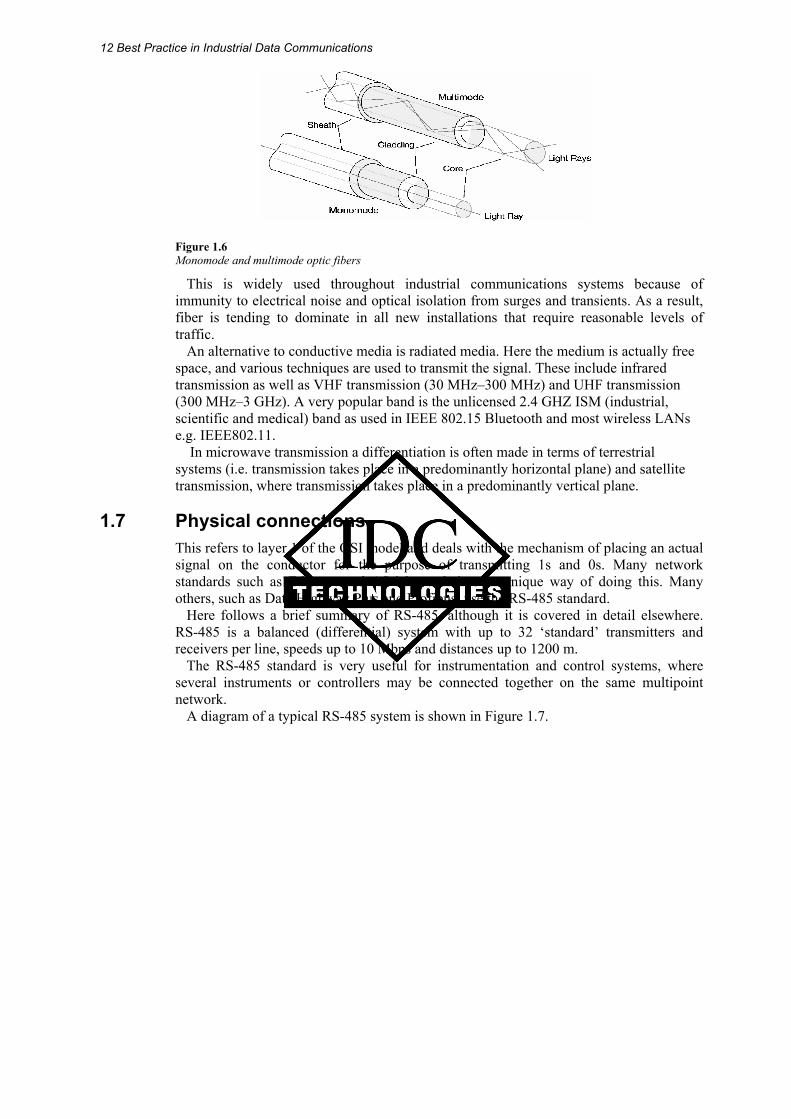
In the case of optic fiber, the signal is conducted as impulses of light. There are two main approaches possible with fiber optic cables, namely:
• Single mode (monomode) cabling, and • Multimode cabling
12 Best Practice in Industrial Data Communications
Figure 1.6 Monomode and multimode optic fibers
This is widely used throughout industrial communications systems because of immunity to electrical noise and optical isolation from surges and transients. As a result, fiber is tending to dominate in all new installations that require reasonable levels of traffic.
An alternative to conductive media is radiated media. Here the medium is actually free space, and various techniques are used to transmit the signal. These include infrared transmission as well as VHF transmission (30 MHz–300 MHz) and UHF transmission (300 MHz–3 GHz). A very popular band is the unlicensed 2.4 GHZ ISM (industrial, scientific and medical) band as used in IEEE 802.15 Bluetooth and most wireless LANs e.g. IEEE802.11. In microwave transmission a differentiation is often made in terms of terrestrial systems (i.e. transmission takes place in a predominantly horizontal plane) and satellite transmission, where transmission takes place in a predominantly vertical plane.
1.7 Physical connections This refers to layer 1 of the OSI model and deals with the mechanism of placing an actual signal on the conductor for the purpose of transmitting 1s and 0s. Many network standards such as Ethernet and AS-i have their own unique way of doing this. Many others, such as Data Highway Plus and Profibus, use the RS-485 standard.
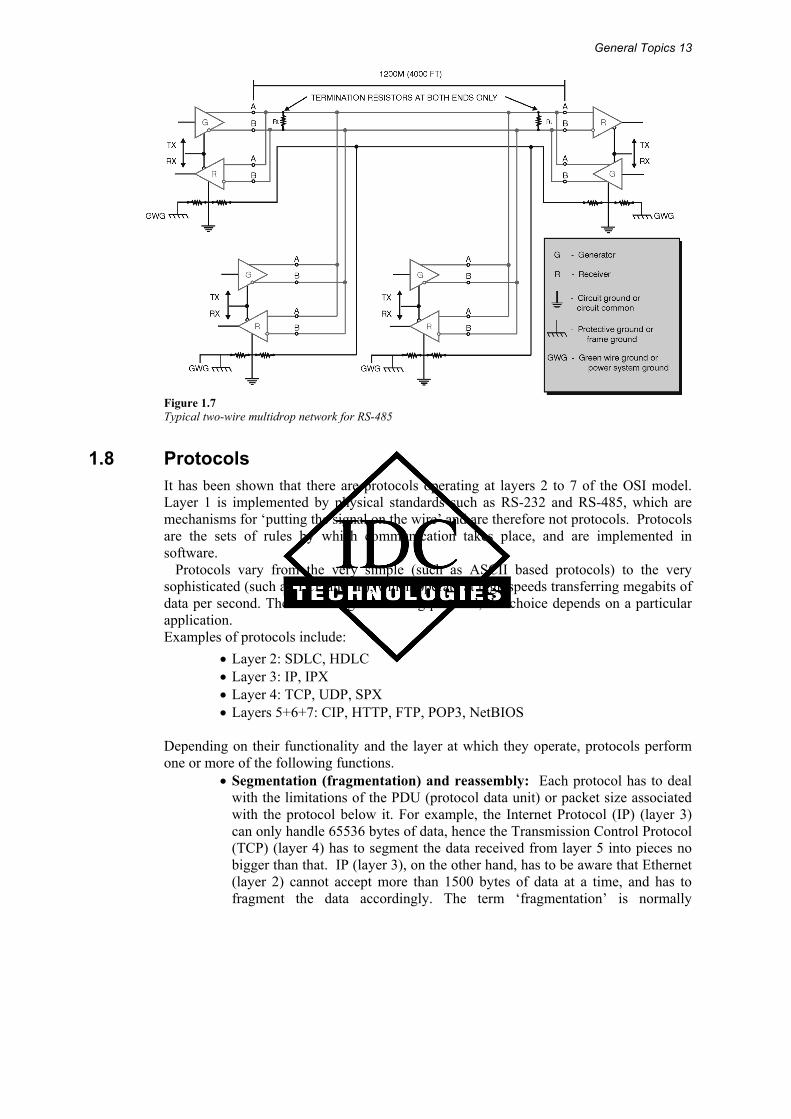
Here follows a brief summary of RS-485, although it is covered in detail elsewhere. RS-485 is a balanced (differential) system with up to 32 ‘standard’ transmitters and receivers per line, speeds up to 10 Mbps and distances up to 1200 m.
The RS-485 standard is very useful for instrumentation and control systems, where several instruments or controllers may be connected together on the same multipoint network.
A diagram of a typical RS-485 system is shown in Figure 1.7.
General Topics 13
Figure 1.7 Typical two-wire multidrop network for RS-485
1.8 Protocols It has been shown that there are protocols operating at layers 2 to 7 of the OSI model. Layer 1 is implemented by physical standards such as RS-232 and RS-485, which are mechanisms for ‘putting the signal on the wire’ and are therefore not protocols. Protocols are the sets of rules by which communication takes place, and are implemented in software.
Protocols vary from the very simple (such as ASCII based protocols) to the very sophisticated (such as TCP and IP), which operate at high speeds transferring megabits of data per second. There is no right or wrong protocol, the choice depends on a particular application.
Examples of protocols include: • Layer 2: SDLC, HDLC • Layer 3: IP, IPX • Layer 4: TCP, UDP, SPX • Layers 5+6+7: CIP, HTTP, FTP, POP3, NetBIOS
Depending on their functionality and the layer at which they operate, protocols perform one or more of the following functions.
• Segmentation (fragmentation) and reassembly: Each protocol has to deal with the limitations of the PDU (protocol data unit) or packet size associated with the protocol below it. For example, the Internet Protocol (IP) (layer 3) can only handle 65536 bytes of data, hence the Transmission Control Protocol (TCP) (layer 4) has to segment the data received from layer 5 into pieces no bigger than that. IP (layer 3), on the other hand, has to be aware that Ethernet (layer 2) cannot accept more than 1500 bytes of data at a time, and has to fragment the data accordingly. The term ‘fragmentation’ is normally
14 Best Practice in Industrial Data Communications
associated with layer 3 whereas the term ‘segmentation’ is normally associated with layer 4. The end result of both is the same but the mechanisms differ. Obviously the data stream fragmented by a protocol on the transmitting side has to be re-assembled by its corresponding peer on the receiving side, so each protocol involved in the process of fragmentation has to add appropriate parameters in the form of sequence numbers, offsets and flags to facilitate this.
• Encapsulation: Each protocol has to handle the information received from the layer above it ‘without prejudice’; i.e. it carries forwards it without regard for its content. For example, the information passed on to IP (layer 3) could contain a TCP header (layer 4) plus an FTP header (layers 5,6,7) plus data from an FTP client (e.g. Cute FTP). IP simply regards this as a package of information to be forwarded, adds its own header with the necessary control information, and passes it down to the next layer (e.g. Ethernet)
• Connection control: Some layer 4 protocols such as TCP create logical connections with their peers on the other side. For example, when browsing the Internet, TCP on the client (user) side has to establish a connection with TCP on the server side before a web site can be accessed. Obviously there are mechanisms for terminating the connection as well
• Ordered delivery: Large messages have to be cut into smaller fragments, but on a packet switching network the different fragments can theoretically travel via different paths to their destination. This results in fragments arriving at their destination out of sequence, which creates problems in rebuilding the original message. This issue is normally addressed at layer 3 and sometimes at layer 4 (anywhere that fragmentation and segmentation takes pace) and different protocols use different mechanisms, including sequence numbers and fragment offsets
• Flow control: The protocol on the receiving side must be able to liaise with its counterpart on the sending side in order not to be overrun by data. In simple protocols this is accomplished by a lock-step mechanism (i.e. each packet sent needs to be acknowledged before the next one can be sent) or XON/XOFF mechanisms where the receiver sends an XOFF message to the sender to pause transmission, then sends an XON message to resume transmission. More sophisticated protocols us ‘sliding windows’. Here, the sliding window is a number that represents the amount of unacknowledged data that can still be sent. The receiver does not have to acknowledge every message, but can from time to time issue blanket acknowledgements for all data received up to a point. As the sender sends data, the window shrinks and as the receiver acknowledges, the window expands accordingly. When the window becomes zero, the transmitter stops until some acknowledgment is received and the window opens up again
• Error control: The sender needs some mechanism by which it can ascertain if the data received is the same as the data sent. This is accomplished by performing some form of checksum on the data to be transmitted, and including the checksum in the header or in a trailer after the data. Types of checksum include vertical and longitudinal parity, block check count (BCC) and cyclic redundancy checking (CRC)
General Topics 15
• Addressing: Protocols at various levels need to identify the physical or logical recipient on the other side. This is done by various means. Layer 4 protocols such as TCP and UDP use port numbers. Layer 3 protocols use a protocol address (such as the IP address for the Internet Protocol) and layer 2 protocols use a hardware (or ‘media’) address such as a station number or MAC address
• Routing: In an internetwork, i.e. a larger network consisting of two or more smaller networks interconnected by routers, the routers have to communicate with each other in order to know the best path to a given destination on the network. This is achieved by routing protocols (RIP, OSPF etc) residing on the routers
• Multiplexing: Some higher-protocols such as TCP can create several ‘logical’ channels on one physical channel. The opposite can be done some lower-level protocols such as PPP where one logical stream of data can be sent over several physical (e.g. dial-up) connections. This mechanism is called multiplexing
1.9 Noise
1.9.1 Sources of electrical noise Typical sources of noise are devices that produce quick changes (or spikes) in voltage or current, such as:
• Large electrical motors being switched on • Fluorescent lighting tubes • Lightning strikes • High voltage surging due to electrical faults • Welding equipment
From a general point of view, there must be three contributing factors for the existence of an electrical noise problem. They are:
• A source of electrical noise • A mechanism coupling the source to the affected circuit • A circuit conveying the sensitive communication signals
1.9.2 Electrical coupling of noise There are four forms of coupling of electrical noise into the sensitive data communications circuits. They are:
• Impedance coupling (sometimes referred to as conductance coupling) • Electrostatic coupling • Magnetic or inductive coupling • Radio frequency radiation (a combination of electrostatic and magnetic)
Each of these noise forms will be discussed in some detail in the following sections.
16 Best Practice in Industrial Data Communications
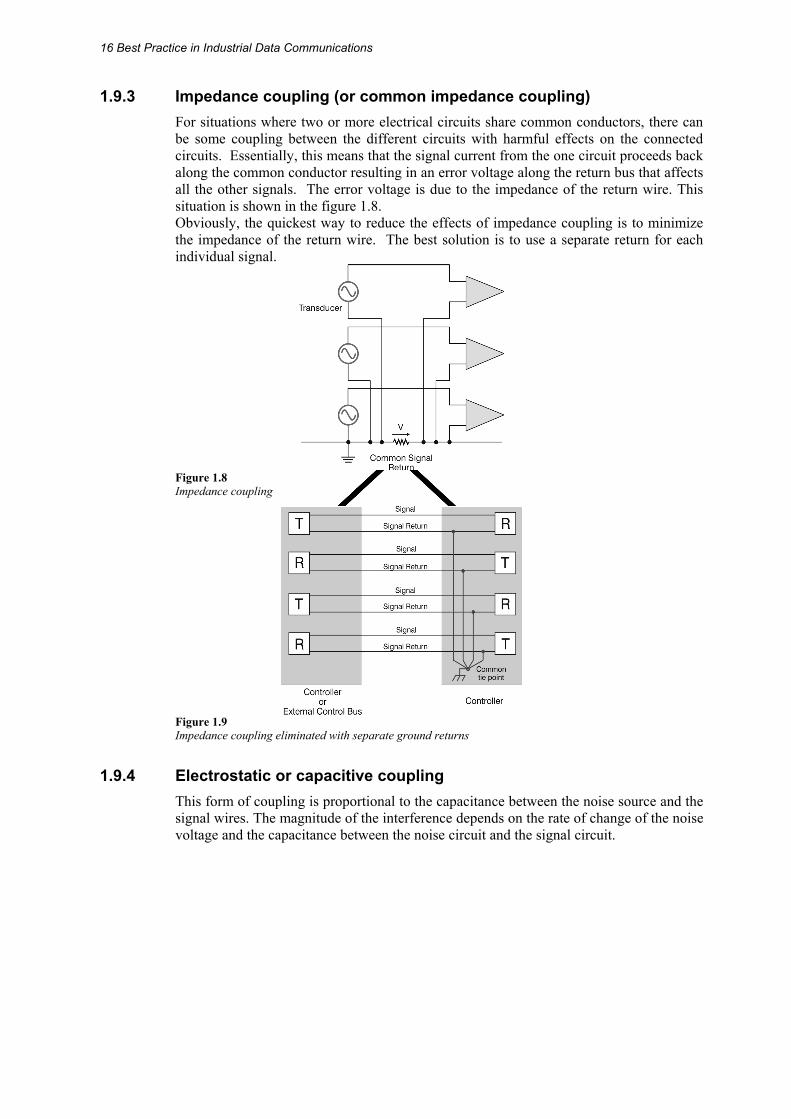
1.9.3 Impedance coupling (or common impedance coupling) For situations where two or more electrical circuits share common conductors, there can be some coupling between the different circuits with harmful effects on the connected circuits. Essentially, this means that the signal current from the one circuit proceeds back along the common conductor resulting in an error voltage along the return bus that affects all the other signals. The error voltage is due to the impedance of the return wire. This situation is shown in the figure 1.8. Obviously, the quickest way to reduce the effects of impedance coupling is to minimize the impedance of the return wire. The best solution is to use a separate return for each individual signal.
Figure 1.8 Impedance coupling
Figure 1.9 Impedance coupling eliminated with separate ground returns
1.9.4 Electrostatic or capacitive coupling This form of coupling is proportional to the capacitance between the noise source and the signal wires. The magnitude of the interference depends on the rate of change of the noise voltage and the capacitance between the noise circuit and the signal circuit.
General Topics 17
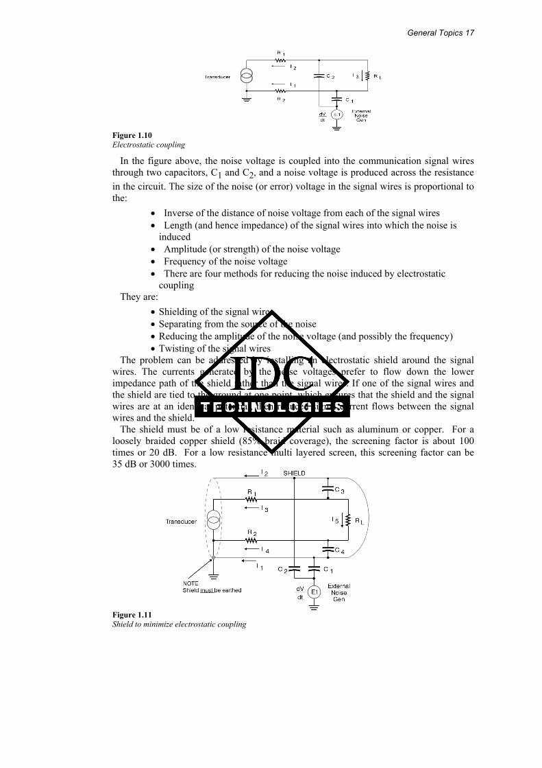
Figure 1.10 Electrostatic coupling
In the figure above, the noise voltage is coupled into the communication signal wires through two capacitors, C1 and C2, and a noise voltage is produced across the resistance in the circuit. The size of the noise (or error) voltage in the signal wires is proportional to the:
• Inverse of the distance of noise voltage from each of the signal wires • Length (and hence impedance) of the signal wires into which the noise is
induced • Amplitude (or strength) of the noise voltage • Frequency of the noise voltage • There are four methods for reducing the noise induced by electrostatic
coupling They are:
• Shielding of the signal wires • Separating from the source of the noise • Reducing the amplitude of the noise voltage (and possibly the frequency) • Twisting of the signal wires
The problem can be addressed by installing an electrostatic shield around the signal wires. The currents generated by the noise voltages prefer to flow down the lower impedance path of the shield rather than the signal wires. If one of the signal wires and the shield are tied to the ground at one point, which ensures that the shield and the signal wires are at an identical potential, then reduced signal current flows between the signal wires and the shield.
The shield must be of a low resistance material such as aluminum or copper. For a loosely braided copper shield (85% braid coverage), the screening factor is about 100 times or 20 dB. For a low resistance multi layered screen, this screening factor can be 35 dB or 3000 times.
Figure 1.11 Shield to minimize electrostatic coupling

18 Best Practice in Industrial Data Communications
Twisting of the signal wires provides a slight improvement in reducing the induced noise voltage by ensuring that C1 and C2 are closer together in value; thus ensuring that any noise voltages induced in the signal wires tend to cancel each other out.
Provision of a shield by a cable manufacturer ensures that the capacitance between the shield and each wire is equal in value, thus eliminating any noise voltages by cancellation.
1.9.5 Magnetic or inductive coupling This depends on the rate of change of the noise current and the mutual inductance between the noise system and the signal wires. Expressed slightly differently, the degree of noise induced by magnetic coupling will depend on the:
• Magnitude of the noise current • Frequency of the noise current • Area enclosed by the signal wires (through which the noise current magnetic
flux cuts) • Inverse of the distance from the disturbing noise source to the
signal wires
The effect of magnetic coupling is shown in Figure 1.12.
Figure 1.12 Magnetic coupling
The easiest way of reducing the noise voltage caused by magnetic coupling is to twist the signal conductors. This results in lower noise due to the smaller area for each loop. This means less magnetic flux to cut through the loop and consequently, a lower induced noise voltage. In addition, the noise voltage that is induced in each loop tends to cancel out the noise voltages from the next sequential loop. It is assumed that the noise voltage is induced in equal magnitudes in each signal wire due to the twisting of the wires giving a similar separation distance from the noise voltage.
The second approach is to use a magnetic shield around the signal wires. The magnetic flux generated from the noise currents induces small eddy currents in the magnetic shield. These eddy currents then create an opposing magnetic flux φ1 to the original flux φ2. This means a lesser flux (φ2 − φ1) reaches our circuit.
General Topics 19
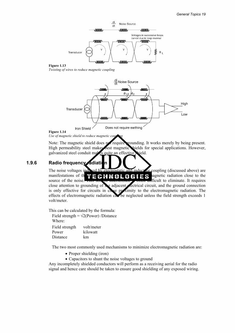
Figure 1.13 Twisting of wires to reduce magnetic coupling
Figure 1.14 Use of magnetic shield to reduce magnetic coupling
Note: The magnetic shield does not require grounding. It works merely by being present. High permeability steel makes best magnetic shields for special applications. However, galvanized steel conduit makes quite an effective shield.
1.9.6 Radio frequency radiation The noise voltages induced by electrostatic and inductive coupling (discussed above) are manifestations of the near field effect, which is electromagnetic radiation close to the source of the noise. This sort of interference is often difficult to eliminate. It requires close attention to grounding of the adjacent electrical circuit, and the ground connection is only effective for circuits in close proximity to the electromagnetic radiation. The effects of electromagnetic radiation can be neglected unless the field strength exceeds 1 volt/meter. This can be calculated by the formula:
Field strength = √2(Power) /Distance Where: Field strength volt/meter Power kilowatt Distance km
The two most commonly used mechanisms to minimize electromagnetic radiation are:
• Proper shielding (iron) • Capacitors to shunt the noise voltages to ground
Any incompletely shielded conductors will perform as a receiving aerial for the radio signal and hence care should be taken to ensure good shielding of any exposed wiring.
20 Best Practice in Industrial Data Communications
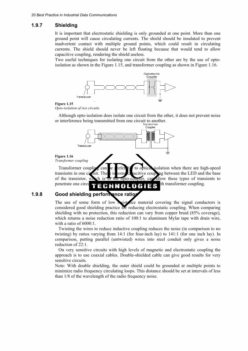
1.9.7 Shielding It is important that electrostatic shielding is only grounded at one point. More than one ground point will cause circulating currents. The shield should be insulated to prevent inadvertent contact with multiple ground points, which could result in circulating currents. The shield should never be left floating because that would tend to allow capacitive coupling, rendering the shield useless. Two useful techniques for isolating one circuit from the other are by the use of opto- isolation as shown in the Figure 1.15, and transformer coupling as shown in Figure 1.16.
Figure 1.15 Opto-isolation of two circuits
Although opto-isolation does isolate one circuit from the other, it does not prevent noise or interference being transmitted from one circuit to another.
Figure 1.16 Transformer coupling
Transformer coupling can be preferable to optical isolation when there are high-speed transients in one circuit. There is some capacitive coupling between the LED and the base of the transistor, which is in the opto-coupler, can allow these types of transients to penetrate one circuit from another. This is not the case with transformer coupling.
1.9.8 Good shielding performance ratios The use of some form of low resistance material covering the signal conductors is considered good shielding practice for reducing electrostatic coupling. When comparing shielding with no protection, this reduction can vary from copper braid (85% coverage), which returns a noise reduction ratio of 100:1 to aluminum Mylar tape with drain wire, with a ratio of 6000:1.
Twisting the wires to reduce inductive coupling reduces the noise (in comparison to no twisting) by ratios varying from 14:1 (for four-inch lay) to 141:1 (for one inch lay). In comparison, putting parallel (untwisted) wires into steel conduit only gives a noise reduction of 22:1.
On very sensitive circuits with high levels of magnetic and electrostatic coupling the approach is to use coaxial cables. Double-shielded cable can give good results for very sensitive circuits. Note: With double shielding, the outer shield could be grounded at multiple points to minimize radio frequency circulating loops. This distance should be set at intervals of less than 1/8 of the wavelength of the radio frequency noise.

General Topics 21
1.9.9 Cable ducting or raceways These are useful in providing a level of attenuation of electric and magnetic fields. These figures are done at 60 Hz for magnetic fields and 100 kHz for electric fields.
Typical screening factors are: • 5 cm (2 inch) aluminum conduit with 0.154 inch thickness: magnetic fields (at
60 Hz) 1.5:1, electric fields (at 100 kHz) 8000:1 • Galvanized steel conduit 5 cm (2 inch), wall thickness 0.154 inch width:
magnetic fields (at 60 Hz) 40:1, electric fields (at 100 kHz) 2000:1
1.10 Cable spacing In situations where there are a large number of cables varying in voltage and current levels, the IEEE518–1982 standard has developed a useful set of tables indicating separation distances for various classes of cables. There are four classification levels of susceptibility for cables. Susceptibility, in this context, is understood to be an indication of how well the signal circuit can differentiate between the undesirable noise and required signal. It follows a data communication physical standard such as RS-232E that would have a high susceptibility and a 1000 volt, 200 amp ac cable that has a low susceptibility.
The four susceptibility levels defined by the IEEE 518 standard are briefly: • Level 1: High
This is defined as analog signals less than 50 volt and digital signals less than 15 volt. This would include digital logic buses and telephone circuits. Data communication cables fall into this category
• Level 2: Medium This category includes analog signals greater than 50 volt and switching circuits
• Level 3: Low This includes switching signals greater than 50 volt and analog signals greater than 50 volt. Currents less than 20 amp are also included in this category
• Level 4: Power This includes voltages in the range 0–1000 volt and currents in the range 20–800 amps. This applies to both ac and dc circuits
IEEE 518 also provides for three different situations when calculating the separation distance required between the various levels of susceptibilities.
In considering the specific case where one cable is a high susceptibility cable and the other cable has a varying susceptibility, the required separation distance would vary as follows:
• Both cables contained in a separate tray 1. Level 1 to Level 2–30 mm 2. Level 1 to Level 3–160 mm 3. Level 1 to Level 4–670 mm
• One cable contained in a tray and the other in conduit 4. Level 1 to Level 2–30 mm 5. Level 1 to Level 3–110 mm 6. Level 1 to Level 4–460 mm
22 Best Practice in Industrial Data Communications
• Both cables contained in separate conduit 7. Level 1 to Level 2–30 mm 8. Level 1 to Level 3–80 mm 9. Level 1 to Level 4–310 mm
Figures are approximate as the original standard is quoted in inches. A few words need to be said about the construction of the trays and conduits. The trays are to be manufactured from metal and firmly grounded with complete continuity throughout the length of the tray. The trays should also be fully covered preventing the possibility of any area being without shielding.
1.10.1 Grounding requirements This is a contentious issue and a detailed discussion laying out all the theory and practice is possibly the only way to minimize the areas of disagreement. The picture is further complicated by different national codes, which whilst not actively disagreeing with the basic precepts of other countries, tend to lay down different practical techniques in the implementation of a good grounding system.
A typical design should be based around three separate ground systems. They are: • The equipment (or instrument) ground • The chassis (or safety) ground • The earth ground
The aims of these systems are:
• To minimize the electrical noise in the system • To reduce the effects of fault or ground loop currents on the instrumentation
system • To minimize the hazardous voltages on equipment due to electrical faults
Ground is defined as a common reference point for all signals in equipment situated at
zero potential. Below 10 MHz, a single point grounding system is the optimum solution. Two key concepts to be considered when setting up an effective grounding system are:
• To minimize the effects of impedance coupling between different circuits (i.e. when three different currents, for example, flow through a common impedance)
• To ensure that ground loops are not created (for example, by mistakenly tying the screen of a cable at two points to ground)
There are three types of grounding system possible as shown in Figure 1.17. The series single point is perhaps the more common; while the parallel single point is the preferred approach with a separate ground system for different groups of signals.

General Topics 23
Figure 1.17 Various grounding configurations
1.10.2 Suppression techniques It is often appropriate to approach the problem of electrical noise proactively by limiting the noise at the source. This requires knowledge of the electrical apparatus that is causing the noise and then attempting to reduce the noise caused here. The two main approaches are shown here.
Figure 1.18 Suppression networks (snubbers)
In Figure 1.18, the inductance will generate a back emf across the contacts when the voltage source applied to it is switched off. This RC network then takes this back emf and thus reduces damage to the contacts.
The voltage can be limited by various combinations of devices, depending on whether the circuit is ac or dc.
24 Best Practice in Industrial Data Communications
Circuit designers should be aware that the response time of the coil could be reduced significantly. For example, the dropout time of a coil can be increased by a factor of ten. Hence this should be approached with caution, where quick response is required from regular switched circuits (apart from the obvious negative impact on safety due to slowness of operation).
Silicon controlled rectifiers (SCRs) and triacs generate considerable electrical noise due to the switching of large currents. A possible solution is to place a correctly sized inductor in series with the switching device.
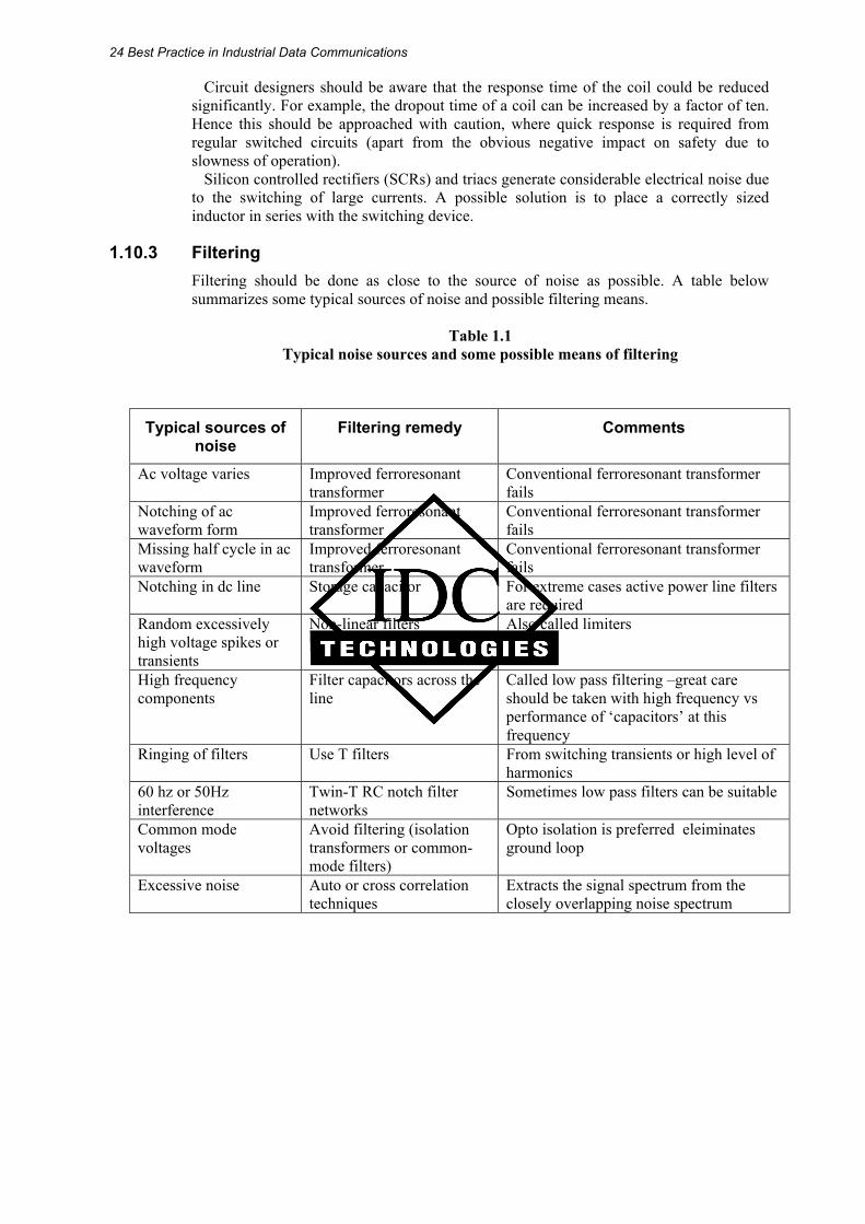
1.10.3 Filtering Filtering should be done as close to the source of noise as possible. A table below summarizes some typical sources of noise and possible filtering means.
Table 1.1
Typical noise sources and some possible means of filtering
Typical sources of noise
Filtering remedy Comments
Ac voltage varies Improved ferroresonant transformer
Conventional ferroresonant transformer fails
Notching of ac waveform form
Improved ferroresonant transformer
Conventional ferroresonant transformer fails
Missing half cycle in ac waveform
Improved ferroresonant transformer
Conventional ferroresonant transformer fails
Notching in dc line Storage capacitor For extreme cases active power line filters are required
Random excessively high voltage spikes or transients
Non-linear filters Also called limiters
High frequency components
Filter capacitors across the line
Called low pass filtering –great care should be taken with high frequency vs performance of ‘capacitors’ at this frequency
Ringing of filters Use T filters From switching transients or high level of harmonics
60 hz or 50Hz interference
Twin-T RC notch filter networks
Sometimes low pass filters can be suitable
Common mode voltages
Avoid filtering (isolation transformers or common-mode filters)
Opto isolation is preferred eleiminates ground loop
Excessive noise Auto or cross correlation techniques
Extracts the signal spectrum from the closely overlapping noise spectrum

General Topics 25
1.11 Ingress protection The ingress protection (IP) rating system is recognized in most countries and is described by several standards, including IEC 60529. It describes the degree of protection offered by an enclosure. This enclosure can be of any description, including a cable, cable assembly, connector body, the casing of a network hub or a large cabinet used to enclose electronic equipment.
Enclosures are rated in the format ‘IP xy’ or ‘IP xyz.’ • The first digit of the IP designation (x) describes the degree of protection
against access to hazardous parts and ingress of solid objects • The second digit (y) designates the degree of protection against water. Refer
to the appropriate sections of IEC 60529 for complete information regarding applications, features, and design tests
• The third digit (z) describes the degree of protection against mechanical impacts and is often omitted. It does, for example, apply to metal enclosures but not to cables or cable assemblies
Here follows a list of meanings attributed to the digits of the IP rating.
1st Protection against foreign objects
2nd Protection against moisture
3rd Protection against mechanical impacts
0 Not protected 0 Not protected 0 Not protected 1 Protected against objects greater
than 50 mm diameter (e.g. hand contact)
1 Protected against dripping water (falling vertically, e.g. condensation)
1 Impact 0.225 joule
2 Protected against objects greater than 12 mm (e.g. fingers)
2 Protected against dripping water when tilted 15° to either side
2 Impact 0.375 joule
3 Protected against objects greater than 2.5 mm (e.g. tolls, wires)
3 Protected against rain up to 60 degrees from vertical
3 Impact 0.60 joule
4 Protected against objects greater than 1.0 mm (e.g. small tools, small wires)
4 Protected against splashing water, any direction
4 N/a
5 Dust protected – limited ingress permitted (no harmful deposits)
5 Protected against water jets (with nozzles)
5 Impact 2.00 joule
6 Dust tight – totally protected against dust (no deposits at all)
6 Protected against heavy seas 6 N/a
7 N/a 7 Protection against effects of immersion
7 Impact 6.00 joule
8 N/a 8 Protection against submersion 8 N/a 9 N/a 9 N/a 9 Impact 20.00 joule
For example, a marking of IP 68 would indicate a dust tight (first digit = 6) piece of equipment that is protected against submersion in water (second digit = 8).

26 Best Practice in Industrial Data Communications