Embed Size (px)
Citation preview
BESIII Electronics and On-Line
BESIII Workshop in Beijing IHEPZhao Jing-wei Sheng Hua-yi He Kang-ling
October 13, 2001
Brief Measurement Tasks Technical Strategy Sub-systems Configurations and Software On-Line System
Brief
BESIII’s sub-detectors are: Vertex Chamber Main Drift Chamber TOF plus CCT Counter Electromagnetic Calorimeter MUON Identifier
Electronics will consist of five sub-systems correspondingly.Total channel amount is about 50K~77K.
Measurement Tasks To measure the time information carried by
detector signal. To measure the charge values carried by
detector output signals or signal amplitude. To deliver the information of fired point
position (x,y) in detector cells. To provide the hit information or sum of
analog signals for making trigger decision. To implement data taking and data
formatting and preprocessing and sub-event packing.
To transfer the packed data to On-line computer system via fast switch network.
Technical Strategy
Short bunch crossing (8 ns) Long trigger latency (2.4us) pipeline must be used.
High luminosity (1×1033cm-2s-1).High event rate.
Parallel processing on-board isneeded to make dead time as small as possible.
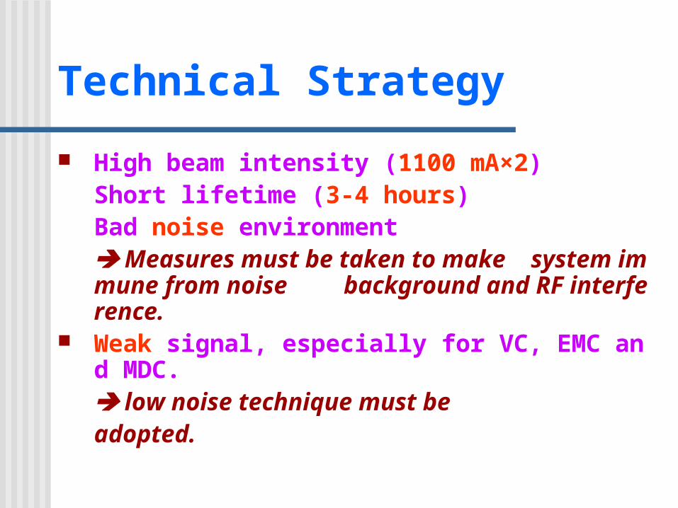
Technical Strategy
High beam intensity (1100 mA×2)Short lifetime (3-4 hours)Bad noise environment Measures must be taken to make system immune from noise background and RF interference.
Weak signal, especially for VC, EMC and MDC. low noise technique must be
adopted.

Sub-system MDC Tasks
Tasks & technical requirements The charge deposition on sense wire (dE/d
x) Charge range : 8~1500 fcResolution : σQ ≈ 4 fc
The drift time of ionized electrons towards sense wires. (to determine the spatial trajectory of particles and the momentum of particles.) Time range : 0~500ns Resolution :σt ≈ 0.5ns
Hit information to trigger
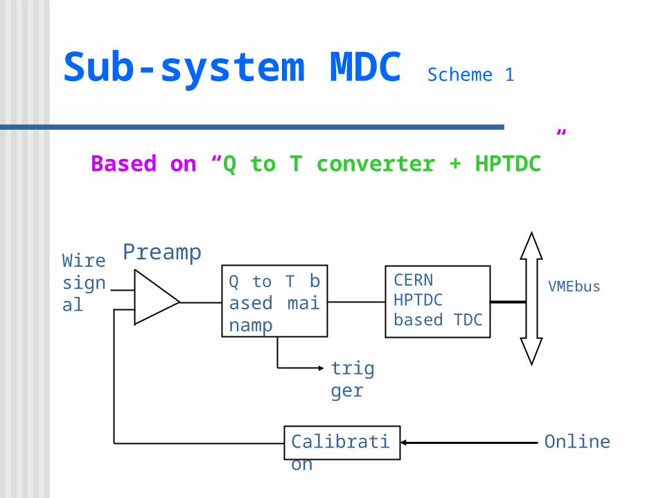
Sub-system MDC Scheme 1
Based on “Q to T converter + HPTDC”
Wiresignal
trigger
Online
VMEbusQ to T based mainamp
Calibration
CERN HPTDC based TDC
Preamp

Sub-system MDC Scheme 1
Preamp.A transimpedance typeLow noiseLow power dissipation
Main amp.Based on Q to T converter – MQT300A
TDC moduleAdopt CERN HPTDC as a key component.
Advantage for above scheme:Simple system: Use only TDC to measure
both the time and charge.
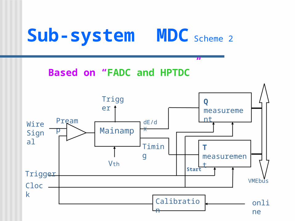
Sub-system MDC Scheme 2
Based on “FADC and HPTDC”
VMEbusClock
online
Preamp
Trigger
Start
WireSignal
Qmeasurement
T measurement
Calibration
Mainamp
Trigger
Timing
dE/dX
Vth

Sub-system MDC Scheme 2
Charge measurement is based on FADC waveform sampling & Numerical integral.10bit and 40MHz FADC is required.9U VME board and 32 ch./board
Time measurement is based on CERN HPTDC chip9U VME board and 96 or 128 ch./board
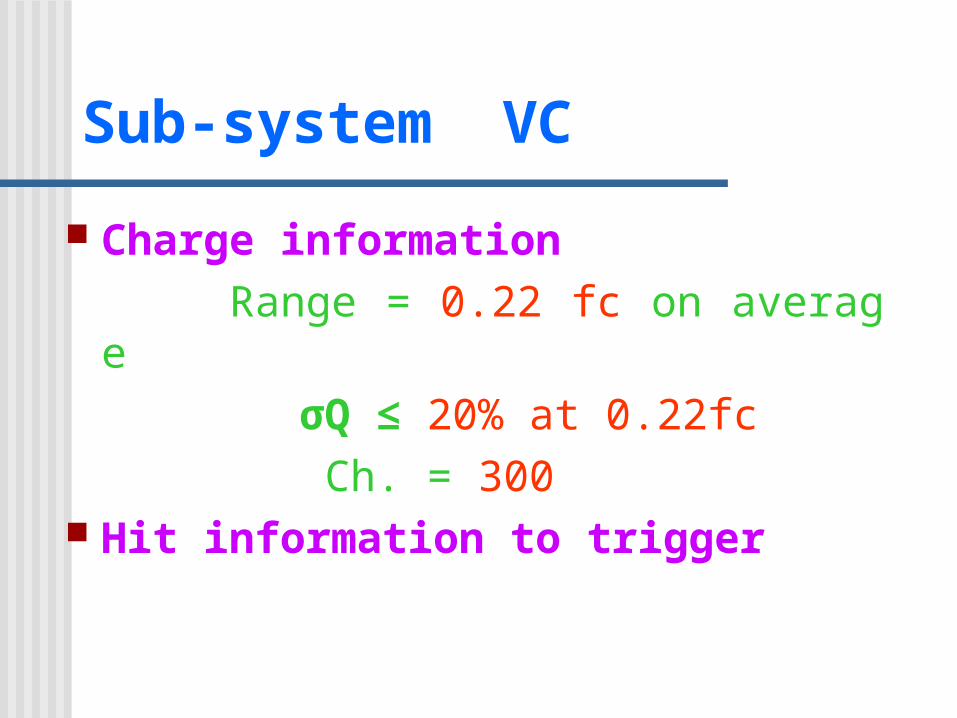
Sub-system VC
Charge information Range = 0.22 fc on average
σQ ≤ 20% at 0.22fc Ch. = 300
Hit information to trigger
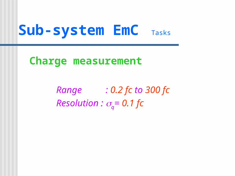
Sub-system EmC Tasks
Charge measurement
Range : 0.2 fc to 300 fcResolution : q= 0.1 fc
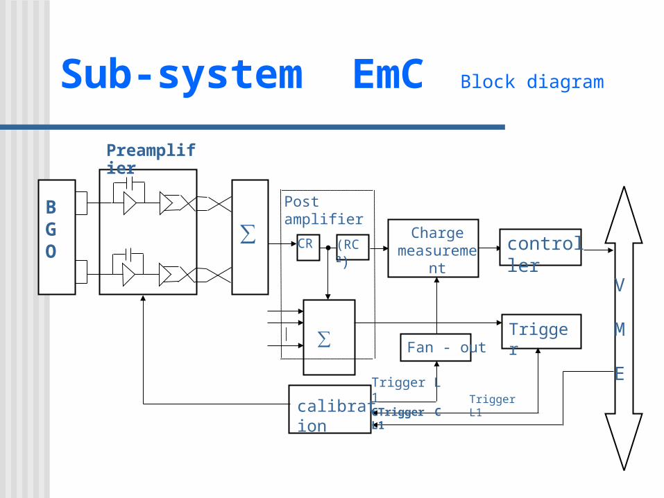
Sub-system EmC Block diagram
Trigger
Post amplifier
V
M
ETrigger L1CTrigger CL1 Trigger L1
CR (RC 2)
∑
calibration
Fan - out
Chargemeasurement controller
Σ
BGO
∑
Preamplifier
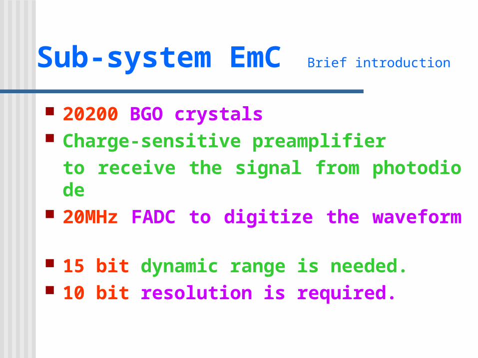
Sub-system EmC Brief introduction
20200 BGO crystals Charge-sensitive preamplifier
to receive the signal from photodiode 20MHz FADC to digitize the waveform 15 bit dynamic range is needed. 10 bit resolution is required.
Sub-system EmC Scheme
Preamplifiers are mounted on the BGO crystals. Two signals from each crystal are added together,
and then feeds to post-amplifier for further amplifying and shaping.
FADC samples the signal with 20MHz. The data are pushed to the digital pipeline. The length of the pipeline equals the trigger L1 latency.
Digitized data within 1.5s interval are read out by a peak finding circuit on arrival of trigger L1. The peak value is stored in a buffer for readout by VME.
Auto Range Encode Circuits are employed to expand the FADC dynamic range from 10 bits to 15 bits.
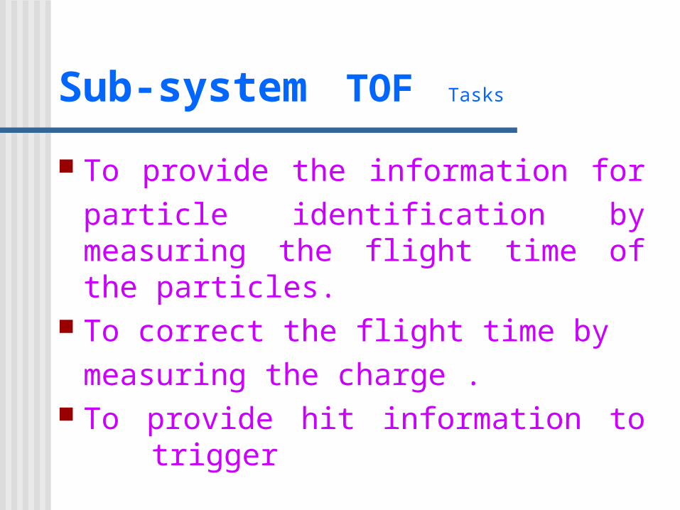
Sub-system TOF Tasks
To provide the information for particle identification by measuring the flight time of the particles.
To correct the flight time by measuring the charge .
To provide hit information to trigger
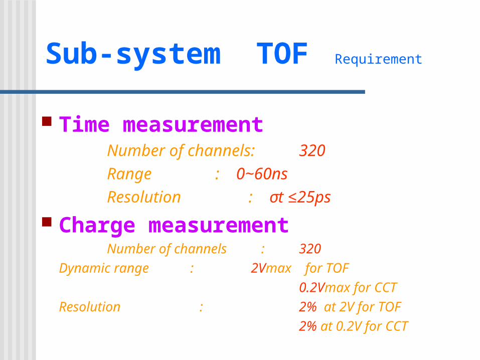
Sub-system TOF Requirement
Time measurement Number of channels: 320 Range : 0~60ns Resolution : σt ≤25ps
Charge measurement Number of channels : 320 Dynamic range : 2Vmax for TOF 0.2Vmax for CCT Resolution : 2% at 2V for TOF 2% at 0.2V for CCT
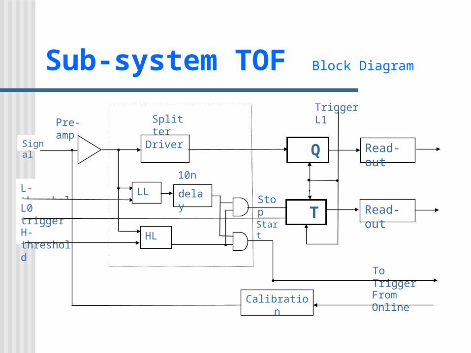
Sub-system TOF Block Diagram
Start
10nsL-threshold
H-threshold
L0 trigger
From Online
To Trigger
Pre-amp Splitter
Stop
Signal Driver
HL
Calibration
LL delay
Trigger L1
Q Read-out
Read-out T
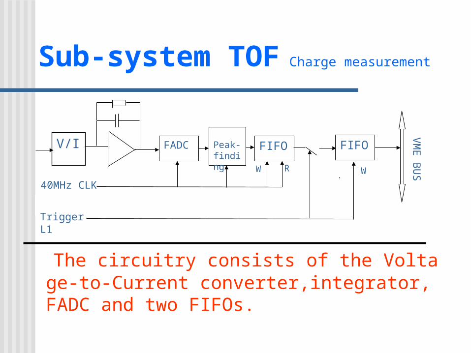
Sub-system TOF Charge measurement
The circuitry consists of the Voltage-to-Current converter,integrator, FADC and two FIFOs.
VM
E
BU
S
W R W
40MHz CLK
V/I FADC Peak-finding
FIFO FIFO
Trigger L1
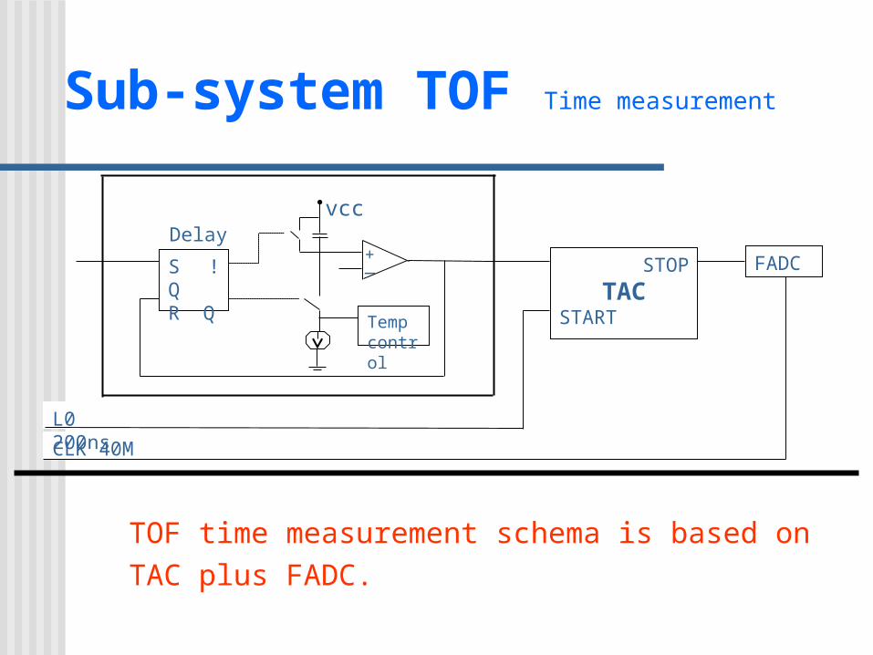
Sub-system TOF Time measurement
TOF time measurement schema is based on TAC plus FADC.
CLK 40M
L0 200ns
Delayvcc
_+
S !QR Q
Tempcontrol
STOP
TACSTART
FADC
Sub-system Muon Tasks
Tasks & technical requirements
To deliver the information of fired point position(x,y) in detector cells.
The hit information to trigger
Sub-system Muon Configuration
Configuration Modules of VME 7 Chains in a module 24 Data of a chain 256 Total data of readout system
10K~30K

Sub-system Muon Diagram of chain
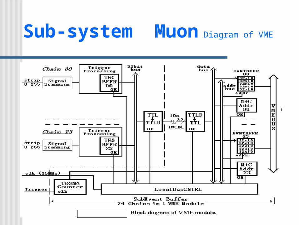
Sub-system Muon Diagram of VME
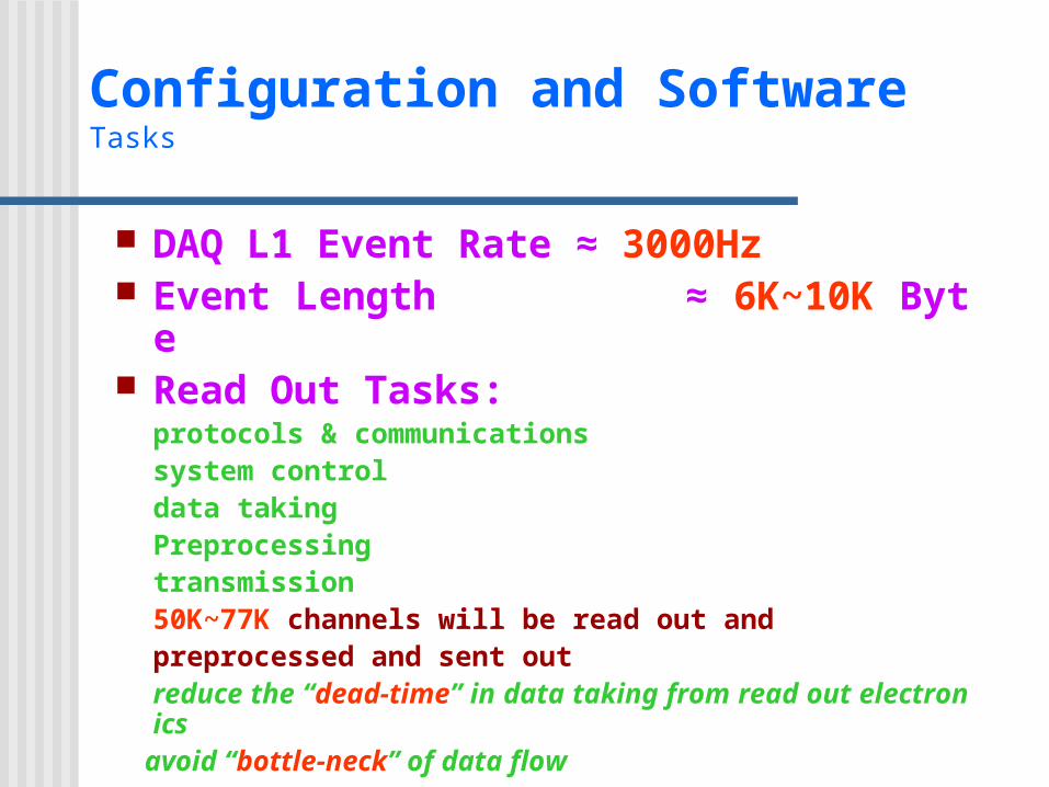
Configuration and Software Tasks
DAQ L1 Event Rate ≈ 3000Hz Event Length ≈ 6K~10K Byte Read Out Tasks:
protocols & communicationssystem controldata taking Preprocessingtransmission
50K~77K channels will be read out and preprocessed and sent outreduce the “dead-time” in data taking from read out electronics
avoid “bottle-neck” of data flow
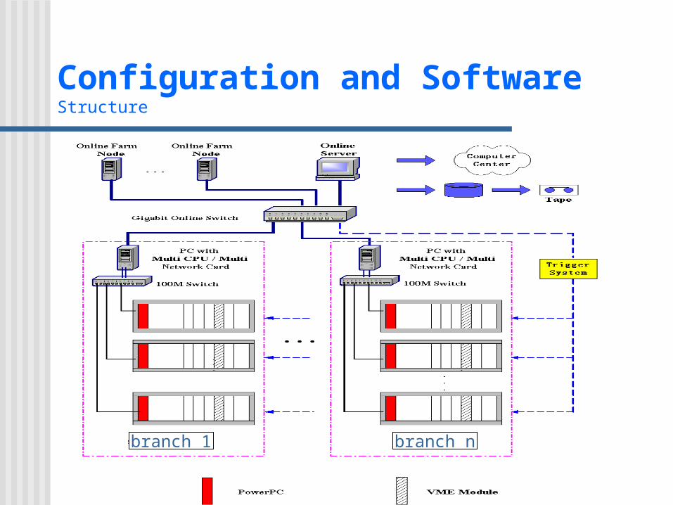
Configuration and Software Structure
branch 1 branch n
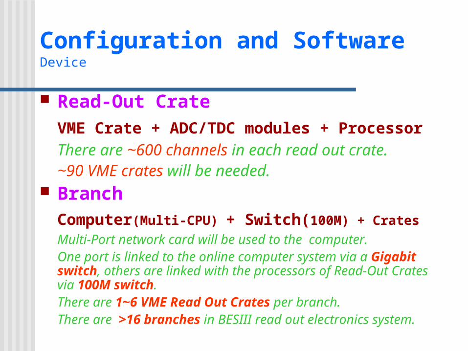
Configuration and Software Device
Read-Out CrateVME Crate + ADC/TDC modules + ProcessorThere are ~600 channels in each read out crate. ~90 VME crates will be needed.
BranchComputer(Multi-CPU) + Switch(100M) + Crates
Multi-Port network card will be used to the computer.One port is linked to the online computer system via a Gigabit switch, others are linked with the processors of Read-Out Crates via 100M switch. There are 1~6 VME Read Out Crates per branch.There are >16 branches in BESIII read out electronics system.
Configuration and Software Design Consideration
Adopt Commercial ProductPowerPC 、 100M Switch 、 Computer and others
Consider to adopt new technique and future device
Performance/cost ratio The software developing environment
VxWorks and x86 BSP 、 PowerPC750 BSP
On-Line System Tasks
Event rate ~2000Hz after L2 filter ~16MBytes/sec to persistent store Event Builder System
Transport information from readout crate to Online(L2) farm
L2 trigger SystemSoftware trigger. Selects events for storage
Online System Run environment monitoring and controlling Experiment monitoring and controlling Human interface
On-Line System Tasks
Data Storagemass storage and transmission via fast network
Slow control system HV control and monitoring Environmental monitoring Dead time & Luminosity monitoring
Tests
On-Line System Requirements
High performance computer Graphics User Interface to experiment Functional requirement
Configuration and constants of system Execute command to FEE and Farm nodes Error message reports for FEE and Farm nodes Calibration Support Diagnostic Tools Data Monitoring Support
Database and network support

Thanks!