Embed Size (px)
Citation preview
Page 1
BES317027-L
A Better Structural Workflow: Integrated Design, Analysis, and Detailing Aaron Vorwerk, AIA, NCARB, EIT, LEED AP BD+C Autodesk, Inc. Ian Coats Autodesk, Inc.
Description
Revit software, Robot Structural Analysis software, and Advance Steel software. You may already have access to these products (via the Architecture, Engineering & Construction Collection), but we’re guessing you’re not using them. And if so, we’re betting that you don’t know what you’re missing! In this hands-on session, we’ll explore the simple, robust, round-trip workflows between Revit 2020, Robot Structural Analysis Professional 2020, and Advance Steel 2020. We’ll start with a basic structural model of a building in Revit, and we’ll develop an understanding of the analytical model that Revit builds concurrently with the creation of structural geometry. Next, we’ll push that model into Robot Structural Analysis software to perform analysis and develop a code group-based design. We’ll then push any changes from Robot Structural Analysis back to Revit. Finally, we’ll explore the detailing capabilities that reside in Revit and Advance Steel, and we’ll end with the production of fully annotated, automated shop drawings from Advance Steel.
Learning Objectives
• Discover the relationship between physical and analytical models in BIM software (Revit).
• Investigate the purpose and capabilities of finite element analysis (FEA) software (Robot Structural Analysis Professional).
• Learn how to exchange models between software tools to facilitate an integrated design, analysis, and detailing workflow.
• Learn how to generate detailed fabrication models directly from design intent models to realize greater efficiencies.

Page 2
Speaker(s)
Aaron Vorwerk is a registered architect, civil/structural engineer-in-training (EIT), LEED AP BD+C, and AEC industry technologist. He advises customers across North America on AEC project lifecycle strategy and workflows. He frequently speaks and writes on AEC-related topics. Aaron has earned graduate degrees in architecture and engineering (M.Arch, MSCE, BSCE); has acquired 25 years’ worth of widespread experience in the AEC industry; and has led BIM transition efforts in two design firms. Ian Coats has enjoyed a construction-oriented career spanning over 20 years with experience of civil / structural projects, including steel detailing and fabrication with a strong emphasis on BIM practices and related technologies. An accomplished speaker, thought leader and mentor, Ian is currently working to drive construction industry efficiencies through the adoption of manufacturing style processes.

Page 3
Structural Tools and Workflows
There are literally hundreds of product offerings in the Autodesk portfolio, dozens of which have application in the AEC space. With that in mind, let’s start by sorting out the most appropriate tools for typical structural engineering workflows.
The Autodesk Structural Toolbox
A general representation of Autodesk tools that might be used in structural workflows (i.e. building and plant/industrial workflows, specifically) is shown in Fig. 1.
Figure 1: Autodesk tools by phase for structural engineering and fabrication
To be clear, the mix of tools employed on every project will vary. In other words, not all tools will be used on every project; conversely, Autodesk and many third parties offer products not listed here capable of providing additional design, analysis, and delivery capabilities if needed.
But for typical engineering projects, an Autodesk-centric workflow will begin with one of two products: Revit (broadly used for buildings and civil structures) or Advance Steel (commonly used for plant/industrial steel structures). It is worth noting that these two products offer bidirectional synchronization, so they are not mutually exclusive.

Page 4
A third tool that might be paired with Revit or Advance Steel on the front end of the work process is Dynamo, an open source visual programming language developed by Autodesk and used to enable powerful computational design and the automation of routine tasks (without requiring programming knowledge) in Autodesk and third-party tools. Dynamo runs on top of both Revit and Advance Steel, with packages for steel connections, analytical modeling, and more; read more at http://dynamobim.org/.
As a project moves from early design into analysis, Robot Structural Analysis Professional enters the picture. Robot Structural Analysis Professional (aka RSA or Robot) is a powerful general-purpose finite element analysis (FEA) platform with full bidirectional interoperability with Revit; we’ll dive into that discussion in much more detail later. It is also possible to exchange information directly between Advance Steel and RSA.
Moving further into the structural workflow, coordination tools begin to play a larger role. These may include the BIM 360 platform (see http://www.autodesk.com/products/bim-360/overview) and very likely Navisworks (http://www.autodesk.com/products/navisworks/overview).
Steel Design and Detailing Workflow
Figure 2: Bridge modeled in Revit and analyzed in RSA
While model coordination typically becomes a focus early in the process, detailing (e.g. steel connections, concrete reinforcement) is also happening at earlier stages. Revit has evolved into a very broad and capable platform, enabling users to design with these details in mind. For example, Revit offers the capability to place steel connections very quickly and check for conformance with AISC or EC3 codes. Full-fledged steel detailing operations resulting in semi-

Page 5
automated, fully annotated shop drawings may be performed by sending Revit models into (and/or synchronizing them with) Advance Steel. See Fig. 3.
Figure 3: Steel design and detailing workflow
Concrete Design and Detailing Workflow

Page 6
Figure 4: Reinforcement modeling in Revit; image courtesy http://vasshaug.net/
When it comes to concrete, Revit supports design-to-detailing workflows. Revit models complex concrete and reinforcement shapes, using a broad set of standard modeling tools, advanced tools such as adaptive component families and free form rebar creation, and computational design via Dynamo. See Fig. 5 for a diagram of this workflow.
Figure 5: Concrete design and detailing workflow
Tools for automated rule-based segmentation, reinforcement, shop drawings and CAM file generation of precast elements in Revit are available in the Structural Precast Extension for Revit. See details at this link. For automation of cast-in-place concrete detailing and fabrication workflows, third party add-ins such SOFiSTiK Reinforcement Detailing and Graitec BIM Designer are also available.
As projects continue to move downstream in the process, information captured during structural design, analysis, and detailing phases can be utilized and supplemented during fabrication and installation using BIM 360 Build. This information, together with commissioning data, can be transferred to BIM 360 Ops at project completion to support owner warranty, operations and maintenance activities from the date of delivery.
The goal of this session, of course, is to walk through the design, analysis, and detailing process. In the sections to come, we will be exploring the interoperability between Revit, Robot Structural Analysis Professional, and Advance Steel.

Page 7
Connecting Design to Analysis
In this section, we’ll explore structural analysis workflows between Autodesk Revit and Autodesk Robot Structural Analysis Professional, beginning with the analytical model in Revit.
The Analytical Model in Revit
Many Revit users do not realize (or simply ignore) the fact that Revit is always ‘taking its best guess’ at creating an analytical model corresponding to a user-authored physical model. Revit builds and maintains this analytical model continuously as a user creates and edits model geometry. See Fig. 6.
Figure 6: Physical and analytical models in Revit; model courtesy the Beck Group
This behavior is important to understand if we are to experience smooth integration when performing structural analysis of Revit models.
Physical Model
The physical model carries information about geometry (heights, lengths, positions, etc.) and materiality (which is important for analysis, as Revit materials contain information on strength and physical characteristics in addition to graphical data).

Page 8
Analytical Model
An analytical model is a simplified 3D representation of the structural physical model. The analytical model consists of those structural components, geometry, material properties, and loads, that together form an engineering system. The analytical model supplies information about member connectivity/fixity and structural purpose (e.g. lateral force resisting member). It can also include member connection forces if the engineer has chosen to supply them.
Revit allows the user to independently adjust the analytical model if the automatically generated version is inaccurate (e.g. at unique structural conditions such as cantilevers). Additionally, Revit enables the user to manually or automatically check to ensure that all members are supported and/or the analytical model remains consistent with the physical model. Settings defining supported elements and model consistency are user-customizable via the Structural Settings dialog (Fig. 7).
Figure 7: Revit Structural Settings dialog
For much more information on the Analytical Model, please refer to the Revit 2020 online help.

Page 9
Robot Structural Analysis Professional
Autodesk® Robot™ Structural Analysis Professional (RSA) finite element analysis software helps engineers more quickly perform simulation, analysis, and code-based design for any type of structure. Fig. 8 highlights some of the key features of this product.
Figure 8: Key features of Robot Structural Analysis Professional
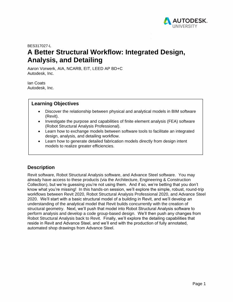
Robot Structural Analysis Professional is a broad platform, supporting many industry, project, and customer types. See Fig. 9 for examples of structures studied in RSA. This section will introduce the use cases and capabilities of the product.
Page 10
Figure 9: Customer examples using Autodesk Robot Structural Analysis Professional
Typical Customers
RSA is used by customers across multiple industries, such as:
▪ Structural engineers
▪ Multidisciplinary engineering teams
▪ Building product manufacturers and fabricators
▪ Large industrial machinery providers
▪ Oil and gas companies and mining firms
Design Versatility
RSA analyzes concrete, steel, and timber designs.
Modeling Flexibility
RSA handles many different types of structures, including:
▪ 2D and 3D frames and trusses
▪ Plates
▪ Shells
▪ Grillages
▪ Plane stress structures
▪ Plane deformation structures
▪ Axisymmetric structures
▪ Volumetric structures
▪ Composite beams

Page 11
Advanced Analytical Capabilities
RSA offers significant computational power, including:
▪ Advanced finite element auto-meshing capabilities.
▪ A wide range of analysis capabilities, including linear and true nonlinear behavior of any
structure:
▪ Compression / tension elements
▪ Cable elements
▪ Non-linear constraints
▪ Material plasticity
▪ Non-linear hinges
▪ 2nd-order effects (non-linear)
▪ 3rd-order effects (P-delta)
▪ State of the art dynamic solvers handle almost any size of structure efficiently, taking full
advantage of multithreading. These include a full complement of dynamic analysis
types:
▪ Modal
▪ Seismic
▪ Spectral
▪ Harmonic and FRF
▪ Time history (linear and non-linear)
▪ Elasto-plastic
▪ Pushover
▪ Footfall
Wind Load Simulation
Unique to RSA is the ability to simulate wind flow around a structure, generating wind loads automatically. This feature is especially useful for structures having a complex geometry, where it is difficult to define appropriate wind loads. The wind simulation feature acts as a wind tunnel and displays colored pressure maps on the model to assist with visualizing and understanding the effects of the wind, as shown in Fig. 10.

Page 12
Figure 10: Wind load simulation in Robot Structural Analysis Professional
Extensibility
RSA uses Microsoft Component Object Model (COM) technology, enabling an open and flexible API. Results Connect, an included add-in for Microsoft Excel (2013 and earlier), connects RSA data directly to Excel. Dynamo is compatible with RSA, enabling access to the structural analysis API with powerful visual programming tools. See Fig. 11 for an example of automated foundation design using Dynamo.

Page 13
Figure 11: Dynamo-driven rebar creation in Revit, analyzable by RSA; image courtesy ABT
For general information on RSA, see http://www.autodesk.com/products/robot-structural-analysis/overview. Much more detailed information on RSA features is found in the Robot Structural Analysis Professional 2020 online help.
New Features and Enhancements RSA has also seen ongoing development in recent releases. Let’s take a brief look at some of the new features in RSA 2020 (excerpt from “Learn What’s New in Robot Structural Analysis 2020”, Tomasz Fudala, Revit Blog).
Code Combinations Regulations Updates
A load combination results when more than one load type acts on the structure. Building codes usually specify a variety of load combinations together with load factors (weightings) for each load type to ensure the safety of the structure under different maximum expected loading scenarios.
Now you can more accurately generate load combinations. The following new code combination regulations have been added into Robot Structural Analysis Professional 2020:
▪ American Codes: LRFD ASCE 7-16 and ASD ASCE 7-16
▪ Canadian Code: NBCC 2015
Enhanced Seismic Analysis
In addition to the seismic load analysis using the Response Spectrum approach, Robot Structural Analysis also contains the Equivalent Lateral Force method. The Equivalent Lateral Force method is an alternative (simplified) approach for determining distribution of seismic base shear force on the height of regular, multistory buildings.
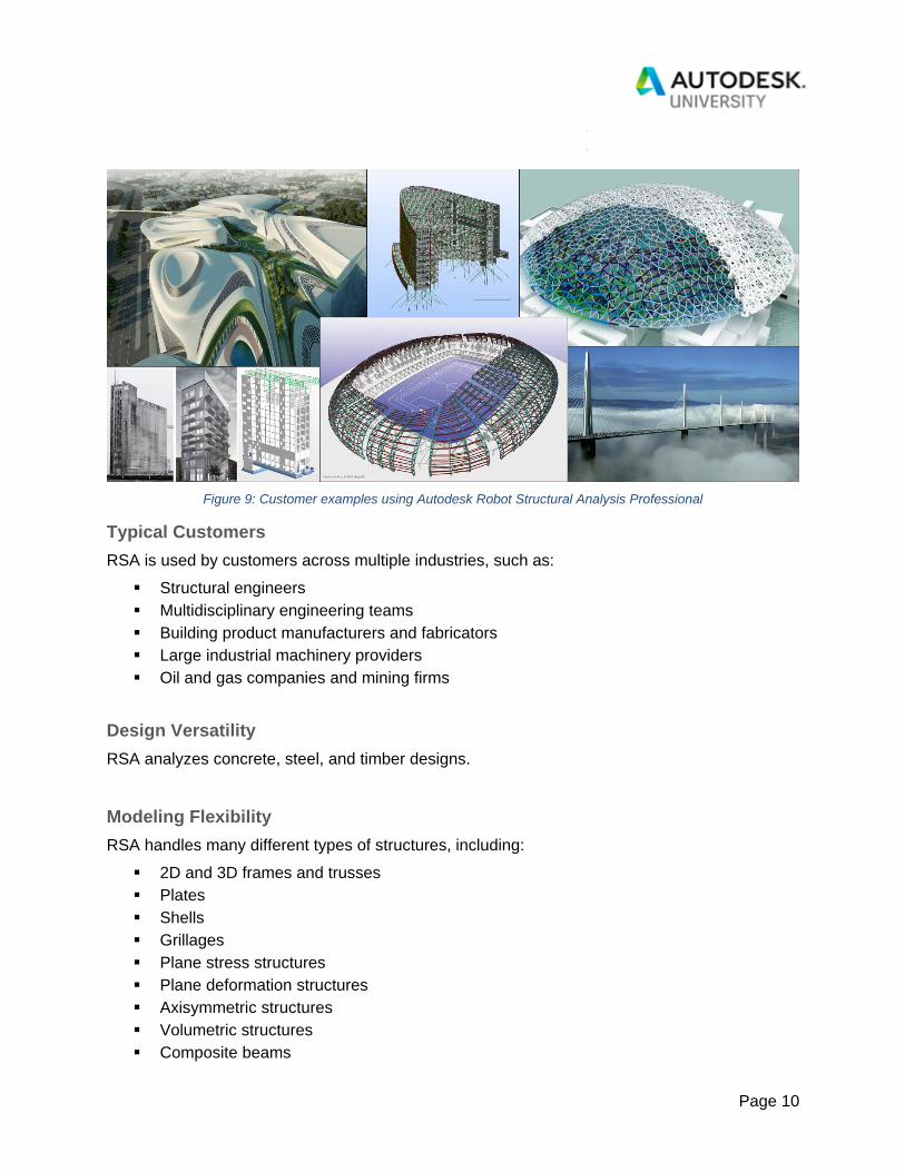
Robot Structural Analysis 2020 contains a new instance of the American standard ASCE 7-16. You can set up a seismic analysis according to ASCE 7-16 for both methods: The Response Spectrum and the Equivalent Lateral Force method.
In addition, a new parameter (Disregard density) in the simplified seismic method (Equivalent Lateral Force) is available. This parameter allows you to exclude the density of the structure element (ρ=0) during the dynamic analysis of the structure. Instead of using self-weight, you
Page 14
may add masses converted from loads. This allows for a control of the mass distribution on a mode.
Figure 12: Seismic Analysis per ASCE 7-16 in RSA 2020
Enhanced Buckling Analysis
Buckling analysis is a technique used to determine buckling loads where a structure becomes unstable. Buckled mode shapes is the characteristic shape associated with a structure’s buckled response.
In Robot Structural Analysis 2020, a new parameter is available in Buckling Analysis (Determine positive critical coefficients only).

Page 15
Figure 13: Buckling Analysis Parameters in RSA 2020
This parameter allows you to exclude the non-physical buckling shapes during the buckling analysis of the structure. This new feature gives engineers greater control over the buckling analysis of the structure.
Enhanced Footfall Analysis
Footfall analysis examines the effect of human footfall loading (interpreted as a harmonic force in a certain frequency interval) on structure vibrations.
Footfall response is of interest to users concerned about the vibration induced in their structures due to walking related activities. As advances in structural design result in more efficient and lighter irregular structures, sensitivity to vibration of the structures is becoming increasingly significant.
In Robot Structural Analysis 2020, footfall analysis according to SCI P354 is updated to Revised Edition of February 2009. This update gives you more reliable results of the effect of human footfall loading.

Page 16
Figure 14: Footfall analysis in RSA 2020
One of the most important results of this analysis is a response factor which specifies how many times the calculated vibrations exceed allowable vibrations. This type of analysis is required for hospitals, laboratories, or sports stadiums.
New Edition of the American Reinforced Concrete Design Code (ACI)
Robot Structural Analysis has extensive support for the design of reinforcement in concrete members. This type of design is further divided into two parts: the design of required reinforcement, which calculates the required steel section areas for concrete members, and the design of provided reinforcement, which can be used to check and design the actual bar counts, types, and layouts for transverse and longitudinal reinforcement in concrete bar elements.
The new ACI 318-14 code is available in the following reinforcement concrete modules: beams, columns, slabs, walls and foundations (isolated and continuous footings). This national standard is also available in the required reinforcement concrete modules for bar and plate elements.

Page 17
Figure 15: Reinforced concrete design example in RSA 2020
New Editions of North American Steel Design Codes (ANSI/AISC and CAN/CSA)
To support structural steel design, Robot provides a Steel/Aluminum Design workspace with all necessary tools.
Robot Structural Analysis 2020 provides current steel design codes to support American and Canadian markets. These include the following:
▪ American Code: ANSI/AISC 360-16 (supplementing ANSI/AISC 360-05 and 360-10)
▪ Canadian Code: CAN/CSA-S16-14 (supplementing CAN/CSA-S16-09)
Engineers based in North America can quickly verify and optimize designs of their steel structures according to the latest building codes.
Steel Section Database
The AISC 15th Edition steel section database has been added and selected by default.
Page 18
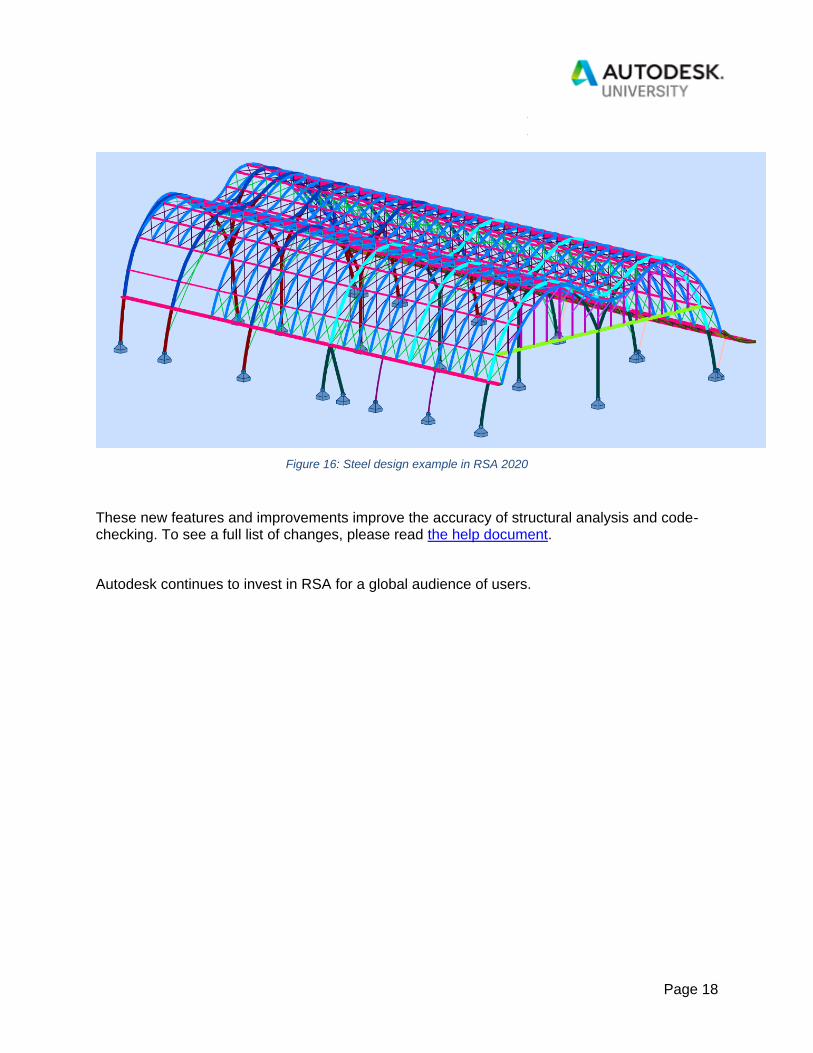
Figure 16: Steel design example in RSA 2020
These new features and improvements improve the accuracy of structural analysis and code-checking. To see a full list of changes, please read the help document.
Autodesk continues to invest in RSA for a global audience of users.
Page 19
Connecting Design to Detailing
In this section, we’ll explore structural detailing workflows between Autodesk Revit and Autodesk Advance Steel, beginning with recent enhancements to Revit’s own detailing capabilities.
Autodesk Revit
Revit is a leading BIM-authoring platform, used around the world by architects, structural engineers, MEP engineers, and others. The product platform continues to experience significant growth and development in many areas, including structural design-to-detailing workflows. Let’s explore some of the more recent additions to Revit.
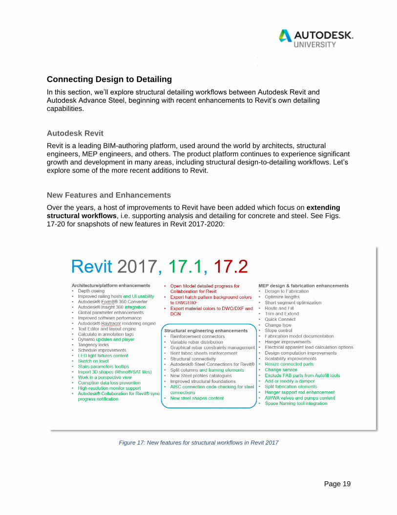
New Features and Enhancements
Over the years, a host of improvements to Revit have been added which focus on extending structural workflows, i.e. supporting analysis and detailing for concrete and steel. See Figs. 17-20 for snapshots of new features in Revit 2017-2020:
Figure 17: New features for structural workflows in Revit 2017

Page 20
Figure 18: New features for structural workflows in Revit 2018

Page 21
Figure 19: New features for structural workflows in Revit 2019

Page 22
Figure 20: New features for structural workflows in Revit 2020
Let’s briefly explore a sampling of structural enhancements introduced in Revit 2018-2020:
Revit 2018: Structural Connections
The Structural Connections library was introduced, enabling detailed modelling of various typical connections. These connections include parametric variables, allowing quick customization of the connection to address a variety of scenarios, as well as a code checking tool, enabling the user to verify the capacity of the connection to carry loads applied at the node.
Page 23
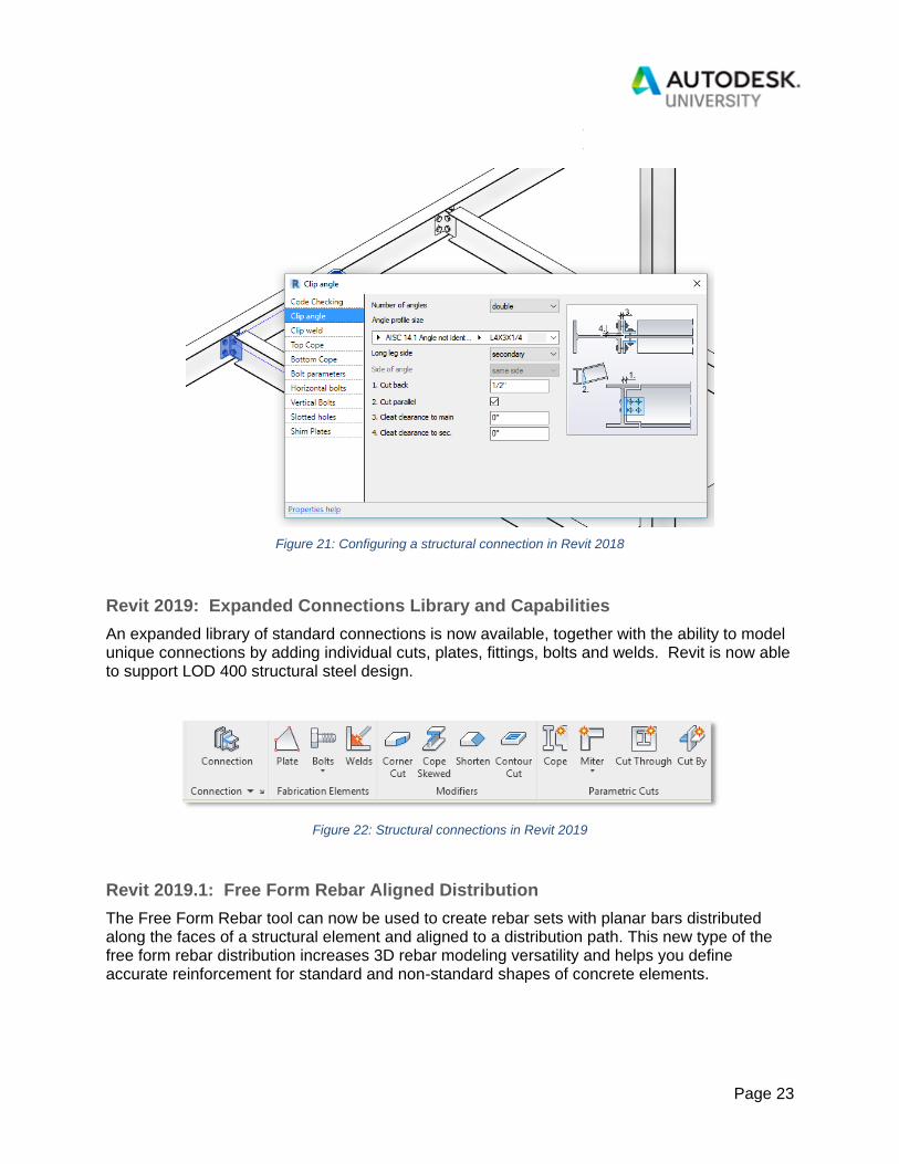
Figure 21: Configuring a structural connection in Revit 2018
Revit 2019: Expanded Connections Library and Capabilities
An expanded library of standard connections is now available, together with the ability to model unique connections by adding individual cuts, plates, fittings, bolts and welds. Revit is now able to support LOD 400 structural steel design.
Figure 22: Structural connections in Revit 2019
Revit 2019.1: Free Form Rebar Aligned Distribution
The Free Form Rebar tool can now be used to create rebar sets with planar bars distributed along the faces of a structural element and aligned to a distribution path. This new type of the free form rebar distribution increases 3D rebar modeling versatility and helps you define accurate reinforcement for standard and non-standard shapes of concrete elements.

Page 24
Figure 23: Free Form Rebar in Revit 2019.1
As with the surface distribution type, you can model aligned distribution type by working in 3D views and selecting the structural element faces to which the bars are aligned. Bars in an aligned distribution are created at the intersection of each individual bar plane with the host surface. All the bars are planar, respect the cover of the host and are aligned to the distribution path.
Get further detail on this feature in Tomasz Fudala’s post on BIM and Beam.
Revit 2019.2: More Automation for Precast Concrete
Update 1 to the Autodesk Structural Precast Extension for Revit 2019 arrived with the release of Revit 2019.2 and introduced new features for customers working on precast and cast-in-place concrete projects. One of the goals here was to enhance connectivity to the fabrication processes, and thus the Extended CAM Export and Unitechnik UXML 7.0 CAM Export tools were concurrently released.
The Extended CAM Export enables Revit models to be more tightly connected to fabrication. Additional types of precast assemblies and rebar cages for elements used in cast-in-place concrete projects can connect to ERP tools and factory master computers using the Unitechnik and PXML files. Rebar cages from any element can now be hooked directly to machines for bar cutting, bending, welding, and other industrial robots, further proving Revit’s ability to be the

Page 25
single source of truth for any type of construction project. To be more technical, this feature enables the generation of CAM files for any selection of shape drive reinforcement, for assemblies containing structural solid wall or structural solid slab system families (including their reinforcement, built-in parts, contours and fabrication parameters), and for assemblies containing loadable families that can host rebar (reinforcement, built-in parts, contours, and fabrication parameters).
Figure 24: A sample of a precast column CAM export as a whole element or rebar cage only
Two features dedicated to enabling faster modelling of precast elements were also delivered at this time: (1) You can now more easily model custom fabric sheets by using not only individual bars, but also rebar sets made of shape driven or free form straight bars; and (2) for additional productivity, users may leverage the Area Reinforcement tool and remove the Area System. Constructability checks are performed as normal, ensuring the sheets comply to the fabrication requirements. The automatic reinforcement tool in the app offers the option to convert the steel bars into a fabric sheet.
Thirteen new hollow core slab families were added, helping engineers and detailers implement these new design solutions faster. The families can be customized using 2 additional void families and 4 profiles.

Page 26
Figure 25: Precast hollow core slab families
This update represented another step towards reducing waste in fabrication with automated deliverables, production processes, bill of materials, and CAM data to drive factory machines. Read much more in Dan Peticila’s post on the Revit Blog.
Revit 2020: The Trend Continues
The initial launch of Revit 2020 brings a slew of features supporting structural workflows. Rather than spotlight one or two major features, here’s a summarized list:
▪ Background processes for detailed steel design
▪ Some of the most commonly used actions for detailed steel design now work in
background calculation processes; actions such as move, copy, align, rotate,
delete, element modification and connection creation are performed in
background calculation processes; this approach lets you perform other actions
while the previous command is still in progress
▪ Improved rebar copy and move logic
Page 27
▪ Get more predictable behavior when copying and moving shape-driven rebar, for
higher accuracy and design intent fidelity
▪ Enhanced multi-rebar annotation
▪ Use multi-rebar annotations for planar parallel free form rebar sets and concrete
host faces
▪ Rebar in model-in-place stairs
▪ Shape-driven or free form rebars can now be hosted in model-in-place stairs
▪ Steel connections for Dynamo
▪ Use the new Autodesk Steel Connections 2020 package for Dynamo to
accelerate the insertion of multiple steel connections based on user-defined rules
▪ Propagation of steel connections
▪ Quickly add similar standard steel connections to your projects by propagating
existing connections
▪ Standard steel connection type parameters
▪ The Revit type capabilities are introduced for standard steel connections to ease
working with these kinds of elements
▪ Customize types for each connection family based on the connection
parameters
▪ Update all the instances of the same type from one place
▪ Reuse the same connection configuration in the same project or in a
different project
▪ Match the properties of a group of connections
▪ New standard steel connection instance property
▪ The Override by Instance property was added in the standard steel connection
type properties
▪ New steel fabrication element instance properties
▪ New steel fabrication shape parameters in schedules, tags, and filters
▪ Hole parameters dialog
▪ Enhanced tags and dimensions for steel elements
▪ Radial and diameter dimensions of circular openings
▪ Dimensions for holes and shear studs
▪ Weld tags now supported in any view
For much more information, refer to the product team’s post on Revit 2020 new features, the What’s New section of the Revit 2020 online help, and the What’s new in Revit 2020.1 post, too.

Page 28
Figure 26: Propagate Connections feature in Revit 2020
These enhancements clearly demonstrate Autodesk’s ongoing commitment to extend design-to-detailing workflows for concrete and steel in Autodesk Revit.

Page 29
Figure 27: Extending structural workflows in Autodesk Revit 2020
Advance Steel
Over five years ago, Autodesk identified that the building construction story for structural steel wasn’t complete and made investments around connecting the design and analysis process with onsite construction activities. This was achieved by adding Advance Steel to the workflow. Advance Steel was developed many years prior and already ran on AutoCAD, so it made sense to acquire that product and integrate it with existing tools in the Autodesk portfolio. Now we have a seamless way to take structural information from design through fabrication without having to deliver the information on 2D drawings to replicate each element in the process.
Page 30
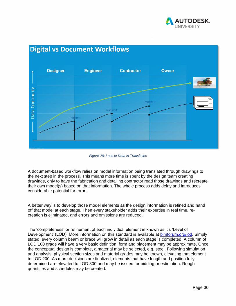
Figure 28: Loss of Data in Translation
A document-based workflow relies on model information being translated through drawings to the next step in the process. This means more time is spent by the design team creating drawings, only to have the fabrication and detailing contractor read those drawings and recreate their own model(s) based on that information. The whole process adds delay and introduces considerable potential for error.
A better way is to develop those model elements as the design information is refined and hand off that model at each stage. Then every stakeholder adds their expertise in real time, re-creation is eliminated, and errors and omissions are reduced.
The ‘completeness’ or refinement of each individual element in known as it’s ‘Level of Development’ (LOD). More information on this standard is available at bimforum.org/lod. Simply stated, every column beam or brace will grow in detail as each stage is completed. A column of LOD 100 grade will have a very basic definition; form and placement may be approximate. Once the conceptual design is complete, a material may be selected, e.g. steel. Following simulation and analysis, physical section sizes and material grades may be known, elevating that element to LOD 200. As more decisions are finalized, elements that have length and position fully determined are elevated to LOD 300 and may be issued for bidding or estimation. Rough quantities and schedules may be created.

Page 31
Figure 29: Levels of Development
Once the major elements in the model reach LOD 350, the design may be handed off to detailing and fabrication. Conceptual connections will have been defined by this time, and perhaps other important design intent features, e.g. stairs, railings, bracing, edge conditions and anchor bolt patterns. The detailer takes these into consideration as they proceed to define every bolt, hole, nut and washer, together with welds and weld preparation information. This results in shop drawing and CNC file creation at LOD 400.
Page 32
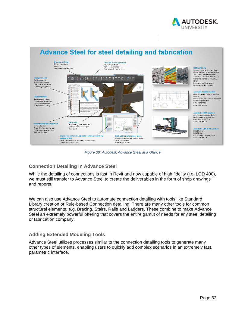
Figure 30: Autodesk Advance Steel at a Glance
Connection Detailing in Advance Steel
While the detailing of connections is fast in Revit and now capable of high fidelity (i.e. LOD 400), we must still transfer to Advance Steel to create the deliverables in the form of shop drawings and reports.
We can also use Advance Steel to automate connection detailing with tools like Standard Library creation or Rule-based Connection detailing. There are many other tools for common structural elements, e.g. Bracing, Stairs, Rails and Ladders. These combine to make Advance Steel an extremely powerful offering that covers the entire gamut of needs for any steel detailing or fabrication company.
Adding Extended Modeling Tools
Advance Steel utilizes processes similar to the connection detailing tools to generate many other types of elements, enabling users to quickly add complex scenarios in an extremely fast, parametric interface.

Page 33
Figure 31: Structural Elements dialog in Advance Steel
Extended Modeling Tools include capabilities for:
• Portal Frame Buildings
• Mono-Pitch Buildings
• Bracing Layout
• Purlin Layout
• Joist Layout
• Trusses
• Cladding Layout
• Straight and Spiral Stairs
• Handrails systems
• Ladders
The interface offers a collection of parametric settings that can be adjusted to address many common scenarios. For more unique installations, each of the extended modeling tools can be further modified manually to adapt to individual scenarios.
Figure 32: Stair tread configuration dialog in Advance Steel

Page 34
Figure 33: Stair stringer configuration dialog in Advance Steel
Checking the Model
Once the model detailing is complete with all connections and extended modeling features added, it is wise to check all the data prior to creation of the fabrication deliverables. This ensures field fit-up as well as data consistency.
Model Browser
The Model Browser facilitates a data-grid centric method of checking model consistency quickly and easily. This means a detailer can see and correct many parameters in a simple interface.
Figure 34: Model browser in Advance Steel

Page 35
There are an infinite number of checks that can be applied through the model browser and elements can be edited directly from the data-grid. Examples include:
▪ Are all the angle fittings set to material grade A36?
▪ Are there any members with lengths exceeding what can be shipped?
▪ Has everything been reviewed internally prior to submittal?
▪ Is every element assigned to the correct Phase, Zone or Sequence?
▪ Has every element been grouped into standard framing types?
Collision Detection
Good practice also dictates that every structural detailer should check the erectability of the model, and Advance Steel contains a tool to verify this.
Figure 35: Clash check in Advance Steel
The collision detection tool examines the entire model to look for areas where one element is occupying the same physical space as another, and it will flag these conditions on a list. Clicking on the list will zoom the model to the selected instance. Clashes can be sorted by volume to sort out those that are glaring errors (that would likely cause re-work onsite) versus small interferences, e.g. where a bolt head encroaches upon the root radius of a beam. The collision detection tool will also identify areas where it would be physically impossible to insert a bolt of the defined length into its intended hole, further assuring erectability.
Page 36
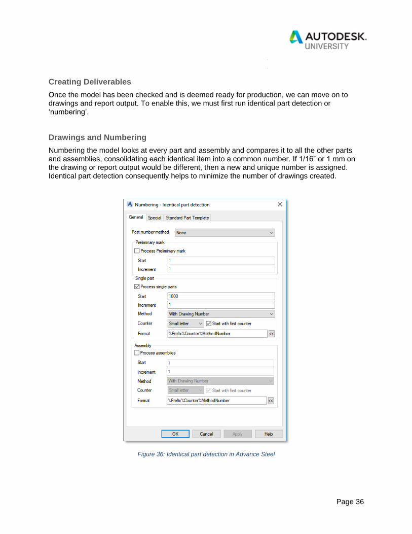
Creating Deliverables
Once the model has been checked and is deemed ready for production, we can move on to drawings and report output. To enable this, we must first run identical part detection or ‘numbering’.
Drawings and Numbering
Numbering the model looks at every part and assembly and compares it to all the other parts and assemblies, consolidating each identical item into a common number. If 1/16” or 1 mm on the drawing or report output would be different, then a new and unique number is assigned. Identical part detection consequently helps to minimize the number of drawings created.
Figure 36: Identical part detection in Advance Steel

Page 37
The style of numbering used is dependent upon the types of drawings that are to be created. There are a multitude of possibilities here, but they can be largely boiled down to two distinct styles:
• Traditional Drawings: Emulating the pencil-and-paper era of structural detailing, where
several assemblies, complete with all their fittings, are detailed out on one large sheet—
with the goal of minimizing the amount of paper used. Items created using this method
will assume the number of the drawing plus a customizable prefix to denote its group. (B
for Beams, C for Columns, D for Diagonal Bracing, P for Plates etc.) followed by a
sequential number. This is further augmented using lower case for parts and upper case
for assemblies:
• B28 would be the 28th unique Beam Assembly on the project.
• C44 would be the 44th unique Column Assembly drawing on the project.
• p21 would be the 21st unique plate part on the project.
Figure 37: Traditional drawing example
• Manufacturing-style Drawings: Each part is detailed on a small, separate sheet, then
an overall Assembly Sheet is created with minimal dimensioning. This tends to be the
more modern and widely adopted method. Items numbered using this method assume a

Page 38
similar but slightly more complex concatenation of the drawings number, the Item
Identifier, (B for Beams, C for Columns, D for Diagonal Bracing, P for Plates etc.) and
the position on the sheet:
• 100C1 would be the first unique column on sheet 100
• 204B3 would be the third unique beam on sheet 204
• 32p8 would be the 8th unique plate on sheet 32.
Figure 38: Manufacturing-style drawing example
Advance Steel can make both styles of drawings (and many variations in between). However, when using the traditional method, Advance Steel will only apply a number to an object in the model once the drawings are created, as the software won’t know what sheet the element will be placed on until it uses up all of the available drawing space prior to processing that specific element.

Page 39
Figure 39: Assembly drawings dialog
The multiple methods of drawing creation are listed on the Drawing Processes Dialog:
• ‘Each’ means one assembly per drawing;
• ‘PageFull’ means multiple assemblies per drawing (if space permits);
• ‘with Parts’ means all the individual parts required to create that assembly will be
detailed out on the drawing too.
Finally, preferred sheet sizes may be selected in this dialog. The items shown in the list are merely suggestions taken from market research into what is most common, but they may be customized or filtered to meet any individual requirement.
Reports
Beyond drawings, a fabrication shop will want to see information from the model extracted in a report format. These can be used for several different purposes:
• Cut lists for preliminary purchasing
• Saw lists for shaping of the delivered sections
• Surface area summaries for painting
• Weights and dimension lists for shipping and loading
• Bolts and Bought-Out parts lists for purchasing
• Drawing Registers

Page 40
• Status Update Lists
Each of these lists can be exported easily, but identical part detection must be applied in order to add summaries and consolidate piece marks.
Figure 40: Example report from Advance Steel
CNC Data
CNC Data, or ‘Computerized Numerical Control’ Data, is a data file containing the geometry definition of each part in the model. It identifies the piece mark, quantity, grade, section size, and all sorts of other geometry including internal cuts (IK blocks), external cuts (AK blocks) bolt holes (BO Blocks) and Scribe Information (SI Blocks).

Page 41
Beamline and plate processing machines in a fabrication shop use this data file to burn sections or plate and add holes or scribing to the physical section automatically, further enhancing productivity.
Figure 41: CNC code example
Updates and Revisions
Finally, in any project, changes and revisions will be required. Advance Steel offers powerful tools to assist in change management.

Page 42
Figure 42: Revisions dialog in Advance Steel
Figure 43: Revision clouds on drawings
Whenever a change happens in the model after drawings have been created, the drawing Document Manager will automatically flag affected drawings to indicate that an update is required. The user may then add a revision—incrementing the identifier and backing up the previous drawing. These changes will automatically generate red clouds around the affected elements, making the change easy to track and explain.

Page 43
Summary
One might ask why and how these integrated workflows provide advantages. In some cases, they require advanced knowledge for a successful implementation. Traditional methods are well known. And the tools to be discussed herein offer proven value when used independently from one another, e.g. the use of Revit or Advance Steel for structural design, RSA for finite element analysis, etc.
The simple truth is that there are synergies to be realized when utilizing more than one of these tools in a workflow, as their interoperability enables a broad set of capabilities supporting structural design-to-detailing workflows. Figs. 44-47 illustrate several customer examples.
Figure 44: Detailed modelling and coordination; images courtesy vasshaug.net and AECOM

Page 44
Figure 45: Integrated analysis; images courtesy the Beck Group
Figure 46: Prefabrication; images courtesy Sundt Construction

Page 45
Figure 47: Connected construction; images courtesy ICA
In closing, workflows leveraging data exchanges and interoperability translate to a better means of doing business in the AEC industry. Autodesk offers tools supporting integrated capabilities for structural design, analysis, and detailing. Maybe it’s time to give them a try!