Embed Size (px)
Citation preview

Bentley Civil Workshop
2013 Bentley LEARNing
Conference
BCR3WK4
OpenRoads Technology - Using Civil Cells
Team Leader: Ian Rosam BSW Product Manager
Team Members: Joe Waxmonsky, Jacquelyn Pettus
Bentley Systems, Incorporated 685 Stockton Drive Exton, PA 19341 www.bentley.com

Workshop: BCR3WK4 - OpenRoads Technology - Using Civil Cells
Copyright © 2013 Bentley Systems, Inc.
This page left intentionally blank.

Workshop: BCR3WK4 - OpenRoads Technology - Using Civil Cells iii
Copyright © 2013 Bentley Systems, Inc.
Table of Contents
Command Index .......................................................................................................... 1
Preface ............................................................................................................... 3
Session Description .......................................................................................................................... 4
Learning Objectives ......................................................................................................................... 4
Chapter 1: Placing Civil Cells ................................................................................ 5
Overview ........................................................................................................................................ 5
Project Description .......................................................................................................................... 5
Getting Started ................................................................................................................................ 6 Exercise: Placing Civil Cells ......................................................................................... 6 Exercise: Review Corridor Object ............................................................................... 8 Exercise: Add Target Aliasing to the Civil Cell Fillets Linear Templates ..................... 8
Chapter Summary ............................................................................................................................ 9
Chapter 2: Integrating with Existing Non Geometric Data ................................ 11
Overview ...................................................................................................................................... 11
Project Description ........................................................................................................................ 11 Exercise: Create Suitable Geometry From Survey Data To Place a Civil Cell ............ 11 Exercise: Place the ‘Connector’ Civil Cell .................................................................. 14 Exercise: Edit the Connector Linear Template to Match the Corridor ..................... 14 Exercise: Place the ‘Driveway’ Civil Cell ................................................................... 15 Exercise: Modify the Profile of the Driveway ........................................................... 16
Chapter Summary .......................................................................................................................... 16
Chapter 3: Essential Horizontal Constructions .................................................. 17
Overview ...................................................................................................................................... 17
Project Description ........................................................................................................................ 17
Getting Started .............................................................................................................................. 18 Exercise: Building The Constraining Horizontal Geometry ....................................... 18 Exercise: Building The Basic T Horizontal Geometry ............................................... 21 Exercise: Testing the Basic T Horizontal Geometry ................................................. 22
Chapter Summary .......................................................................................................................... 22
Chapter 4: Essential Vertical Constructions ...................................................... 23
Overview ...................................................................................................................................... 23
Project Description ........................................................................................................................ 23 Exercise: Creating Simple Base Vertical Geometry .................................................. 24 Exercise: Create The Projected Vertical Geometry .................................................. 25 Exercise: Create The Fillet Vertical Geometry .......................................................... 26
Command Index
iv Workshop: BCR3WK4 - OpenRoads Technology - Using Civil Cells
Copyright © 2013 Bentley Systems, Inc.
Exercise: Create The Control Line Along the Reference Geometry Connecting the Fillets Geometry ................................................................................................. 26
Chapter Summary .......................................................................................................................... 27
Chapter 5: Building Terrains and Applying Surface Templates ........................ 29
Overview ...................................................................................................................................... 29
Project Description ......................................................................................................................... 29 Exercise: Create Terrain from Geometry .................................................................. 30 Optional Exercise: Modify Feature Types in the Terrain .......................................... 32 Exercise: Apply Surface Template to the Terrain ...................................................... 33
Chapter Summary .......................................................................................................................... 34
Chapter 6: Applying Linear Templates ................................................................ 35
Overview ...................................................................................................................................... 35
Project Description ......................................................................................................................... 35 Exercise: Apply Linear Templates ............................................................................. 35
Chapter Summary .......................................................................................................................... 37
Chapter 7: Creating and Managing Civil Cells .................................................... 39
Overview ...................................................................................................................................... 39
Project Description ......................................................................................................................... 39 Exercise: Creating and Managing the Civil Cell ......................................................... 39
Chapter Summary .......................................................................................................................... 41
Appendix A: Civil Cell Commands ......................................................................... 43
Civil Cell Commands ....................................................................................................................... 43
Appendix B: Best Practices .................................................................................... 45
Overview ...................................................................................................................................... 45
Creating Civil Cells .......................................................................................................................... 45
Using a DGNLib ............................................................................................................................... 45
Civil Cells Content ........................................................................................................................... 46
Civil Cell Naming ............................................................................................................................. 46
Start / End Locations and Appropriate Snaps ............................................................................... 46
Using Points .................................................................................................................................... 47
Civil AccuDraw ................................................................................................................................ 47
Testing Civil Cells ............................................................................................................................ 47
Use of Corridors and Linear Templates in Civil Cell ....................................................................... 47
Learning Paths .......................................................................................................... 49
Assessment .............................................................................................................. 51
Glossary .............................................................................................................. 53
Workshop: BCR3WK4 - OpenRoads Technology - Using Civil Cells 1
Copyright © 2013 Bentley Systems, Inc.
Command Index Add as Corridor Clipping Boundary .............................................................................................................41
Add Features ................................................................................................................................... 29, 30, 31
Apply Surface Template ............................................................................................................ 29, 30, 33, 53
Change Feature Type ....................................................................................................................... 29, 31, 32
Civil AccuDraw ............................................................................................. 17, 19, 20, 21, 22, 46, 47, 48, 57
Civil AccuDraw Settings ...............................................................................................................................18
Civil Cell Browser ......................................................................................................................... 6, 13, 14, 15
Corridor Objects ............................................................................................................................................ 8
Create 3D Automatically ....................................................................................................................... 24, 27
Create Civil Cell ........................................................................................................ 17, 22, 23, 29, 35, 39, 40
Create from Elements ........................................................................................................................... 29, 30
Delta Station ............................................................................................................ 17, 18, 19, 20, 21, 47, 48
End Conditions ...................................................................................................................................... 37, 41
Exchange Model ..........................................................................................................................................12
Features Definition Toggle Bar .................................................................................................. 17, 19, 24, 27
Key Station ......................................................................................................................................... 9, 48, 57
Level Display ................................................................................................................................................13
Linear Template ............................................................................... 4, 7, 8, 14, 34, 35, 36, 37, 43, 47, 53, 55
Parabolic Method ........................................................................................................................................26
Partial Offset Element ......................................................................................................... 17, 18, 23, 26, 27
Place Civil Cell .................................................................... 5, 6, 11, 13, 14, 15, 17, 22, 23, 29, 35, 39, 41, 45
Plan By 3D Element ............................................................................................................................... 12, 13
Process Civil Cell .................................................................................................................................... 39, 41
Profile by Constant Elevation ................................................................................................................ 23, 24
Profile by Slope from Element............................................................................................................... 23, 25
Quick Profile Transition ................................................................................................................... 23, 25, 26
Remove Feature .................................................................................................................................... 30, 31
Saved View Group .......................................................................................................................................14
Simple Arc .............................................................................................................................................. 17, 21

Command Index
2 Workshop: BCR3WK4 - OpenRoads Technology - Using Civil Cells
Copyright © 2013 Bentley Systems, Inc.
Single Offset Entire Element ................................................................................................................. 17, 21
Single Offset Partial ..................................................................................................................................... 19
Target Aliasing..................................................................................................................................... 8, 9, 58
Terrain Feature Definition .......................................................................................................................... 33
Use Active Feature .......................................................................................................................... 17, 19, 24
Workshop: BCR3WK4 - OpenRoads Technology - Using Civil Cells 3
Copyright © 2013 Bentley Systems, Inc.
Preface In this workshop, you will learn the principles behind civil cells through their use, modification and construction. Civil Cells inherently draw on all aspects of the V8i SELECTseries 3 tools and encapsulates design intent at their very heart of everything.
We have structured the contents of the exercises herein to provide insight into best practices and allow interaction with a broad range of the available tools; however, we will not use every tool. It is the intent of this workshop to give guidance to allow engineers to see how to build good civil cells and see how they could provide benefit in your own engineering projects and help progress / complete projects in a shorter time frame than normal.
This workshop is equally applicable for the MX, InRoads or GEOPAK families of products. Each product contains identical toolsets and identical workflows. The only differences between the three products for the tools are slight differences in the use of feature definitions and some differences in the back-end interaction with other native toolsets, such as drainage. In this workshop, we will use Power InRoads V8i SELECT series 3 released version, along with the Metric Civil Workspace.
There are more exercises in this manual than we will have time to cover today. We will all complete the basic set of exercises, and for those veteran users in the group who complete them and still have time left in the exercise session, you are welcome to work on the optional.
In order for all participants to design the same layout and to stay on course and on time, we request that all participants utilize the files as listed in the workshop materials. At the beginning of each chapter, we will start with a fresh set of data. This ensures that everyone is using the same data. Plus, we have added data to avoid redundant work. For example, we draw some of the edges of pavement in the lab so you can understand the workflow, but have drawn the remainder in for expediency of time.
The workshop guide is yours to take with you. If you don’t finish all the exercises, or just want to work with the dataset upon return to your office, the datasets (both initial and completed files) are provided on the Conference DVD. Many workshops will also have videos of all exercises on the DVD.
Note Prerequisite Knowledge Level: Participant should have a basic understanding of road design principles, be familiar with CAD drafting and have a basic knowledge of OpenRoads technology.

Preface
4 Workshop: BCR3WK4 - OpenRoads Technology - Using Civil Cells
Copyright © 2013 Bentley Systems, Inc.
SESSION DESCRIPTION
This hands-on workshop teaches the OpenRoads technology of Civil cells for “similar but different” designs that captures and reuses these designs, while easily adjusting their parameters. Learn how to model intersections, traffic islands, driveways, field entrances, and a host of other standards with parametric settings by simply placing a “cell.” This presentation teaches the concept of “civil parametric cells,” and the possibilities are only limited by your imagination. For all Bentley civil intermediate users.
LEARNING OBJECTIVES
After this course you will be able to:
Be able to manage and apply Civil Cells Understand the fundamental geometric principles behind Civil Cells Understand and manage terrains use in Civil Cells Understand and manage area templates use in Civil Cells Understand and manage Linear Templates / template use in Civil Cells Be able to build well-formed Civil Cells
At the end of this training session, an assessment will be given. We will review all assessment questions and answers to see what you have learned.
Workshop: BCR3WK4 - OpenRoads Technology - Using Civil Cells 5
Copyright © 2013 Bentley Systems, Inc.
Chapter 1: Placing Civil Cells
OVERVIEW
In this session we will introduce the basic concept of civil cells and their use. We will explore and use the civil cells supplied by the workspace and introduce general concepts that will be explored in more detail later on.
PROJECT DESCRIPTION
In this workshop we will be completing the basic steps that can be applied to many different scenarios. The intention here is to give an overview of the use of Civil Cells supplied in the Metric Civil Workspace, the interaction with the civil model and the tools available. Many of the constructions used in the creation that will be of benefit in many of the other technology workshops.
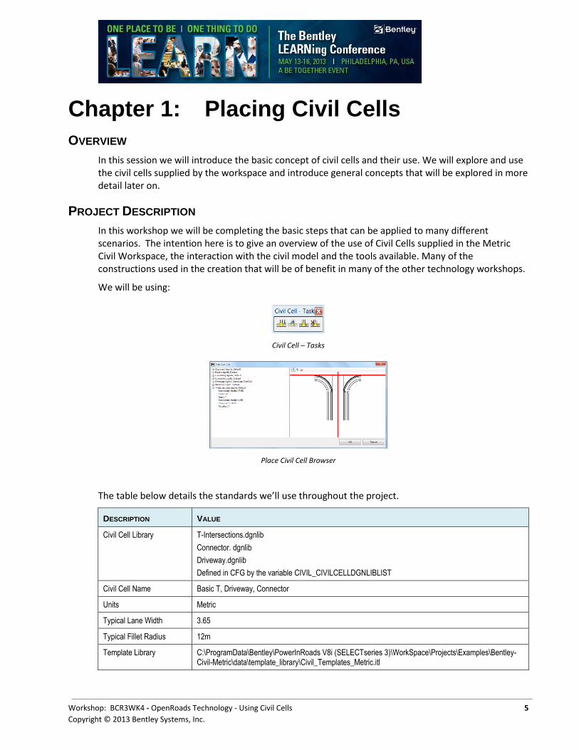
We will be using:
Civil Cell – Tasks
Place Civil Cell Browser
The table below details the standards we’ll use throughout the project.
DESCRIPTION VALUE
Civil Cell Library T-Intersections.dgnlib
Connector. dgnlib
Driveway.dgnlib
Defined in CFG by the variable CIVIL_CIVILCELLDGNLIBLIST
Civil Cell Name Basic T, Driveway, Connector
Units Metric
Typical Lane Width 3.65
Typical Fillet Radius 12m
Template Library C:\ProgramData\Bentley\PowerInRoads V8i (SELECTseries 3)\WorkSpace\Projects\Examples\Bentley-Civil-Metric\data\template_library\Civil_Templates_Metric.itl
Getting Started
6 Workshop: BCR3WK4 - OpenRoads Technology - Using Civil Cells
Copyright © 2013 Bentley Systems, Inc.
GETTING STARTED
In this first section, we will review some of the tools and settings that will be used throughout the workshop. We are using the Civil workspace. For easy accessibility, we will dock the tools within the MicroStation view.
Exercise: Placing Civil Cells
Exercise Objective: Place Basic T intersection and integrate it with the corridor.
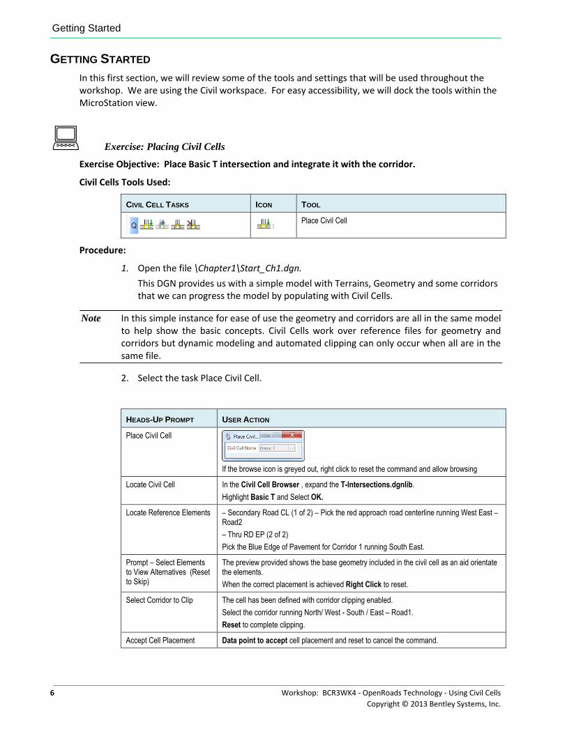
Civil Cells Tools Used:
CIVIL CELL TASKS ICON TOOL
Place Civil Cell
Procedure:
1. Open the file \Chapter1\Start_Ch1.dgn.
This DGN provides us with a simple model with Terrains, Geometry and some corridors that we can progress the model by populating with Civil Cells.
Note In this simple instance for ease of use the geometry and corridors are all in the same model to help show the basic concepts. Civil Cells work over reference files for geometry and corridors but dynamic modeling and automated clipping can only occur when all are in the same file.
2. Select the task Place Civil Cell.
HEADS-UP PROMPT USER ACTION
Place Civil Cell
If the browse icon is greyed out, right click to reset the command and allow browsing
Locate Civil Cell In the Civil Cell Browser , expand the T-Intersections.dgnlib.
Highlight Basic T and Select OK.
Locate Reference Elements – Secondary Road CL (1 of 2) – Pick the red approach road centerline running West East – Road2
– Thru RD EP (2 of 2)
Pick the Blue Edge of Pavement for Corridor 1 running South East.
Prompt – Select Elements to View Alternatives (Reset to Skip)
The preview provided shows the base geometry included in the civil cell as an aid orientate the elements.
When the correct placement is achieved Right Click to reset.
Select Corridor to Clip The cell has been defined with corridor clipping enabled.
Select the corridor running North/ West - South / East – Road1.
Reset to complete clipping.
Accept Cell Placement Data point to accept cell placement and reset to cancel the command.
Getting Started
Workshop: BCR3WK4 - OpenRoads Technology - Using Civil Cells 7
Copyright © 2013 Bentley Systems, Inc.
Note The Civil Cell placement makes assumptions on element directions and attempts to resolve element direction so as to place correctly in the first instance. This is assisted by the intersection location between reference elements being within 10% of the elements length as this helps provide the correct initial orientation.
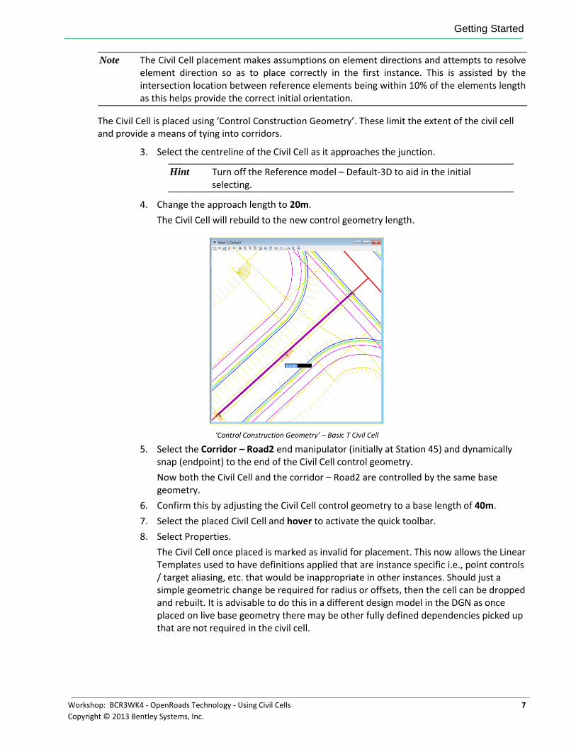
The Civil Cell is placed using ‘Control Construction Geometry’. These limit the extent of the civil cell and provide a means of tying into corridors.
3. Select the centreline of the Civil Cell as it approaches the junction.
Hint Turn off the Reference model – Default-3D to aid in the initial selecting.
4. Change the approach length to 20m.
The Civil Cell will rebuild to the new control geometry length.
‘Control Construction Geometry’ – Basic T Civil Cell
5. Select the Corridor – Road2 end manipulator (initially at Station 45) and dynamically snap (endpoint) to the end of the Civil Cell control geometry.
Now both the Civil Cell and the corridor – Road2 are controlled by the same base geometry.
6. Confirm this by adjusting the Civil Cell control geometry to a base length of 40m.
7. Select the placed Civil Cell and hover to activate the quick toolbar.
8. Select Properties.
The Civil Cell once placed is marked as invalid for placement. This now allows the Linear Templates used to have definitions applied that are instance specific i.e., point controls / target aliasing, etc. that would be inappropriate in other instances. Should just a simple geometric change be required for radius or offsets, then the cell can be dropped and rebuilt. It is advisable to do this in a different design model in the DGN as once placed on live base geometry there may be other fully defined dependencies picked up that are not required in the civil cell.
Getting Started
8 Workshop: BCR3WK4 - OpenRoads Technology - Using Civil Cells
Copyright © 2013 Bentley Systems, Inc.
Exercise: Review Corridor Object
Exercise Objective: Open the corridor object for Road1 and inspect the references to the Civil Cell.
1. Select the corridor handles for Road1 and activate the quick tool bar.
2. Navigate on the toolbar to the Corridor Creation Tools Icon and expand the list.
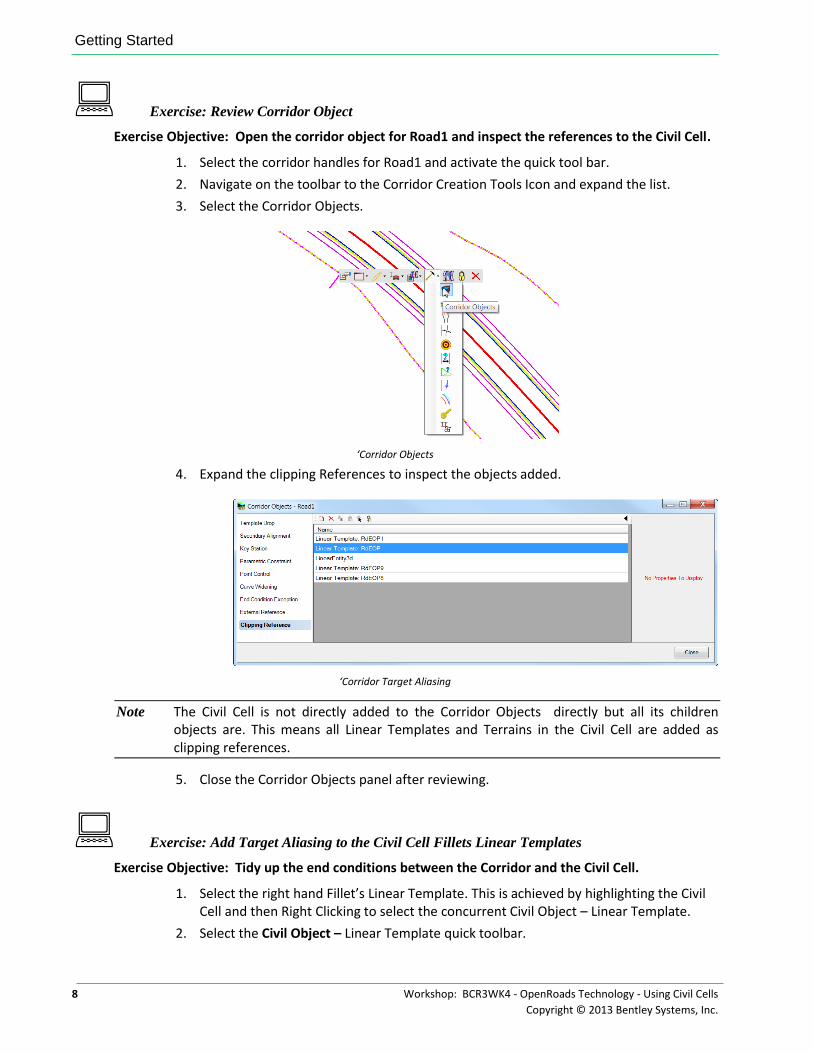
3. Select the Corridor Objects.
‘Corridor Objects
4. Expand the clipping References to inspect the objects added.
‘Corridor Target Aliasing
Note The Civil Cell is not directly added to the Corridor Objects directly but all its children objects are. This means all Linear Templates and Terrains in the Civil Cell are added as clipping references.
5. Close the Corridor Objects panel after reviewing.
Exercise: Add Target Aliasing to the Civil Cell Fillets Linear Templates
Exercise Objective: Tidy up the end conditions between the Corridor and the Civil Cell.
1. Select the right hand Fillet’s Linear Template. This is achieved by highlighting the Civil Cell and then Right Clicking to select the concurrent Civil Object – Linear Template.
2. Select the Civil Object – Linear Template quick toolbar.
Chapter Summary
Workshop: BCR3WK4 - OpenRoads Technology - Using Civil Cells 9
Copyright © 2013 Bentley Systems, Inc.
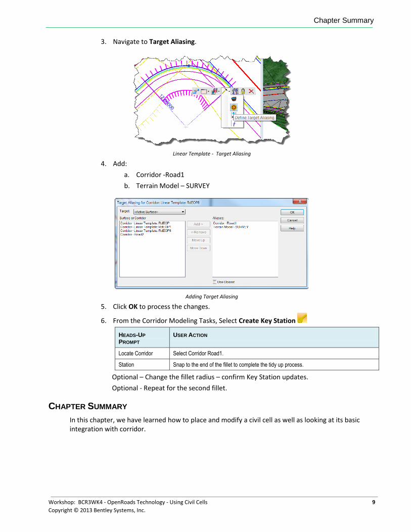
3. Navigate to Target Aliasing.
Linear Template - Target Aliasing
4. Add:
a. Corridor -Road1
b. Terrain Model – SURVEY
Adding Target Aliasing
5. Click OK to process the changes.
6. From the Corridor Modeling Tasks, Select Create Key Station
HEADS-UP
PROMPT USER ACTION
Locate Corridor Select Corridor Road1.
Station Snap to the end of the fillet to complete the tidy up process.
Optional – Change the fillet radius – confirm Key Station updates.
Optional - Repeat for the second fillet.
CHAPTER SUMMARY
In this chapter, we have learned how to place and modify a civil cell as well as looking at its basic integration with corridor.

Chapter Summary
10 Workshop: BCR3WK4 - OpenRoads Technology - Using Civil Cells
Copyright © 2013 Bentley Systems, Inc.
This page left intentionally blank.
Workshop: BCR3WK4 - OpenRoads Technology - Using Civil Cells 11
Copyright © 2013 Bentley Systems, Inc.
Chapter 2: Integrating with Existing Non Geometric Data
OVERVIEW
In this chapter we will go beyond the assumption of new geometric design and consider how we can target existing non geometric features when placing civil cells.
PROJECT DESCRIPTION
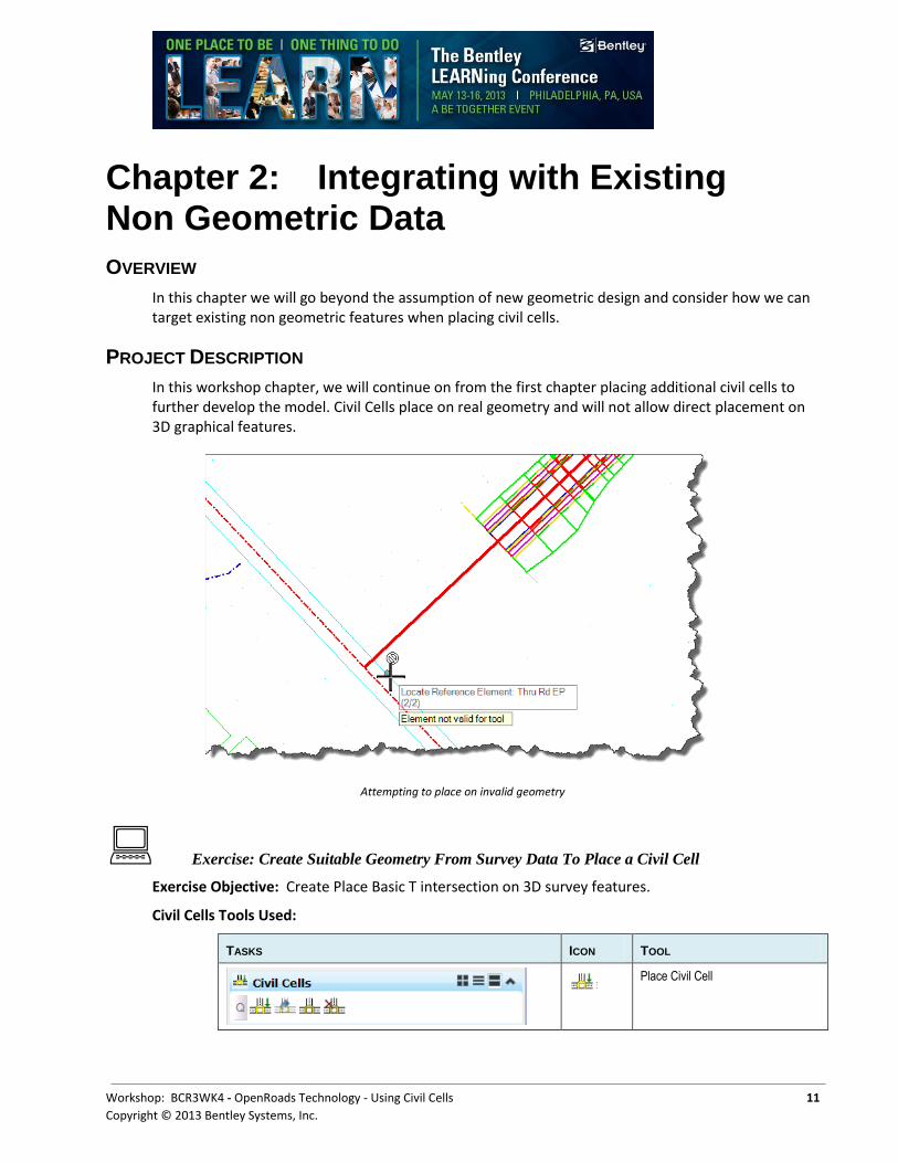
In this workshop chapter, we will continue on from the first chapter placing additional civil cells to further develop the model. Civil Cells place on real geometry and will not allow direct placement on 3D graphical features.
Attempting to place on invalid geometry
Exercise: Create Suitable Geometry From Survey Data To Place a Civil Cell
Exercise Objective: Create Place Basic T intersection on 3D survey features.
Civil Cells Tools Used:
TASKS ICON TOOL
Place Civil Cell
Project Description
12 Workshop: BCR3WK4 - OpenRoads Technology - Using Civil Cells
Copyright © 2013 Bentley Systems, Inc.
Plan By 3D Element
Procedure:
1. Open the file \Chapter2\Start_Ch2.dgn.
2. Try and place the Basic T at the location the view opened.
Note You will be unable to place the Civil Cell as the cylan line represting surveyed 3D feature will return ‘Element not valid for tool’. Civil Cells only place on Geometry so we need a way to create geometry that is usable by Civil Cells.
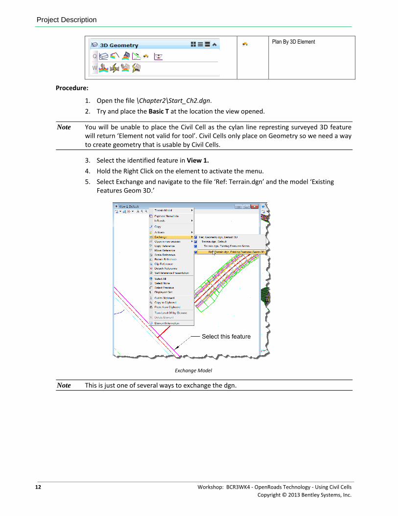
3. Select the identified feature in View 1.
4. Hold the Right Click on the element to activate the menu.
5. Select Exchange and navigate to the file ‘Ref: Terrain.dgn’ and the model ‘Existing Features Geom 3D.’
Exchange Model
Note This is just one of several ways to exchange the dgn.
Project Description
Workshop: BCR3WK4 - OpenRoads Technology - Using Civil Cells 13
Copyright © 2013 Bentley Systems, Inc.
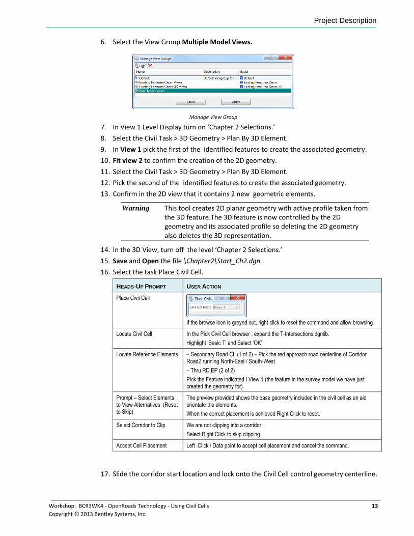
6. Select the View Group Multiple Model Views.
Manage View Group
7. In View 1 Level Display turn on ‘Chapter 2 Selections.’
8. Select the Civil Task > 3D Geometry > Plan By 3D Element.
9. In View 1 pick the first of the identified features to create the associated geometry.
10. Fit view 2 to confirm the creation of the 2D geometry.
11. Select the Civil Task > 3D Geometry > Plan By 3D Element.
12. Pick the second of the identified features to create the associated geometry.
13. Confirm in the 2D view that it contains 2 new geometric elements.
Warning This tool creates 2D planar geometry with active profile taken from the 3D feature.The 3D feature is now controlled by the 2D geometry and its associated profile so deleting the 2D geometry also deletes the 3D representation.
14. In the 3D View, turn off the level ‘Chapter 2 Selections.’
15. Save and Open the file \Chapter2\Start_Ch2.dgn.
16. Select the task Place Civil Cell.
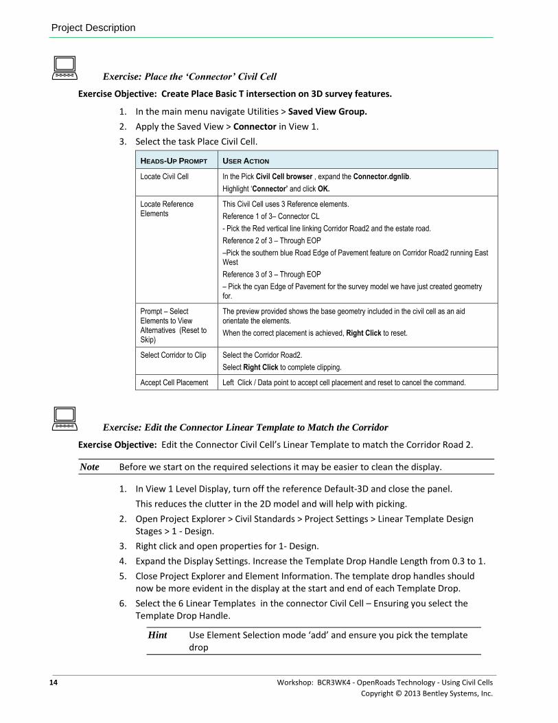
HEADS-UP PROMPT USER ACTION
Place Civil Cell
If the browse icon is greyed out, right click to reset the command and allow browsing
Locate Civil Cell In the Pick Civil Cell browser , expand the T-Intersections.dgnlib.
Highlight ‘Basic T’ and Select ‘OK’
Locate Reference Elements – Secondary Road CL (1 of 2) – Pick the red approach road centerline of Corridor Road2 running North-East / South-West
– Thru RD EP (2 of 2)
Pick the Feature indicated I View 1 (the feature in the survey model we have just created the geometry for).
Prompt – Select Elements to View Alternatives (Reset to Skip)
The preview provided shows the base geometry included in the civil cell as an aid orientate the elements.
When the correct placement is achieved Right Click to reset.
Select Corridor to Clip We are not clipping into a corridor.
Select Right Click to skip clipping.
Accept Cell Placement Left Click / Data point to accept cell placement and cancel the command.
17. Slide the corridor start location and lock onto the Civil Cell control geometry centerline.
Project Description
14 Workshop: BCR3WK4 - OpenRoads Technology - Using Civil Cells
Copyright © 2013 Bentley Systems, Inc.
Exercise: Place the ‘Connector’ Civil Cell
Exercise Objective: Create Place Basic T intersection on 3D survey features.
1. In the main menu navigate Utilities > Saved View Group.
2. Apply the Saved View > Connector in View 1.
3. Select the task Place Civil Cell.
HEADS-UP PROMPT USER ACTION
Locate Civil Cell In the Pick Civil Cell browser , expand the Connector.dgnlib.
Highlight ‘Connector’ and click OK.
Locate Reference Elements
This Civil Cell uses 3 Reference elements.
Reference 1 of 3– Connector CL
- Pick the Red vertical line linking Corridor Road2 and the estate road.
Reference 2 of 3 – Through EOP
–Pick the southern blue Road Edge of Pavement feature on Corridor Road2 running East West
Reference 3 of 3 – Through EOP
– Pick the cyan Edge of Pavement for the survey model we have just created geometry for.
Prompt – Select Elements to View Alternatives (Reset to Skip)
The preview provided shows the base geometry included in the civil cell as an aid orientate the elements.
When the correct placement is achieved, Right Click to reset.
Select Corridor to Clip Select the Corridor Road2.
Select Right Click to complete clipping.
Accept Cell Placement Left Click / Data point to accept cell placement and reset to cancel the command.
Exercise: Edit the Connector Linear Template to Match the Corridor
Exercise Objective: Edit the Connector Civil Cell’s Linear Template to match the Corridor Road 2.
Note Before we start on the required selections it may be easier to clean the display.
1. In View 1 Level Display, turn off the reference Default-3D and close the panel.
This reduces the clutter in the 2D model and will help with picking.
2. Open Project Explorer > Civil Standards > Project Settings > Linear Template Design Stages > 1 - Design.
3. Right click and open properties for 1- Design.
4. Expand the Display Settings. Increase the Template Drop Handle Length from 0.3 to 1.
5. Close Project Explorer and Element Information. The template drop handles should now be more evident in the display at the start and end of each Template Drop.
6. Select the 6 Linear Templates in the connector Civil Cell – Ensuring you select the Template Drop Handle.
Hint Use Element Selection mode ‘add’ and ensure you pick the template drop
Project Description
Workshop: BCR3WK4 - OpenRoads Technology - Using Civil Cells 15
Copyright © 2013 Bentley Systems, Inc.
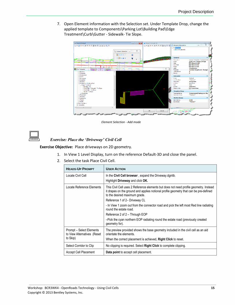
7. Open Element information with the Selection set. Under Template Drop, change the applied template to Components\Parking Lot\Building Pad\Edge Treatment\Curb\Gutter - Sidewalk- Tie Slope.
Element Selection - Add mode
Exercise: Place the ‘Driveway’ Civil Cell
Exercise Objective: Place driveways on 2D geometry.
1. In View 1 Level Display, turn on the reference Default-3D and close the panel.
2. Select the task Place Civil Cell.
HEADS-UP PROMPT USER ACTION
Locate Civil Cell In the Civil Cell browser , expand the Driveway.dgnlib.
Highlight Driveway and click OK.
Locate Reference Elements This Civil Cell uses 2 Reference elements but does not need profile geometry. Instead it drapes on the ground and applies notional profile geometry that can be pre-defined to the desired maximum grade.
Reference 1 of 2– Driveway CL
- In View 1 zoom out from the connector road and pick the left most Red line radiating round the estate road.
Reference 2 of 2 – Through EOP
–Pick the cyan northern EOP radiating round the estate road (previously created geometry for).
Prompt – Select Elements to View Alternatives (Reset to Skip)
The preview provided shows the base geometry included in the civil cell as an aid orientate the elements.
When the correct placement is achieved, Right Click to reset.
Select Corridor to Clip No clipping is required. Select Right Click to complete clipping.
Accept Cell Placement Data point to accept cell placement.
Chapter Summary
16 Workshop: BCR3WK4 - OpenRoads Technology - Using Civil Cells
Copyright © 2013 Bentley Systems, Inc.
Exercise: Modify the Profile of the Driveway
Exercise Objective: Review the vertical profile defining the 3D Driveway and edit.
1. Hover over the yellow CL of the placed Driveway Civil Cell in View 1. 2. Confirm the tooltip as ‘Line: Original_Offset’ and select.
Hint You may need to right click through the available selections to get to the feature that tooltips as ‘Line: Original_Offset.’
3. With the yellow CL selected, right click and Select Open Profile Model. 4. Open View 3 and click in the view to confirm as the profile model. 5. Select the profile to see the geometry manipulators.
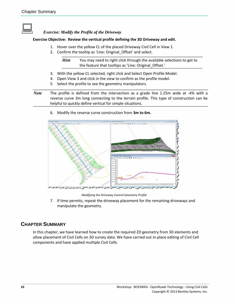
Note The profile is defined from the intersection as a grade line 1.25m wide at -4% with a reverse curve 3m long connecting to the terrain profile. This type of construction can be helpful to quickly define vertical for simple situations.
6. Modify the reverse curve construction from 3m to 6m.
Modifying the Driveway Control Geometry Profile
7. If time permits, repeat the driveway placement for the remaining driveways and manipulate the geometry.
CHAPTER SUMMARY
In this chapter, we have learned how to create the required 2D geometry from 3D elements and allow placement of Civil Cells on 3D survey data. We have carried out in-place editing of Civil Cell components and have applied multiple Civil Cells.
Workshop: BCR3WK4 - OpenRoads Technology - Using Civil Cells 17
Copyright © 2013 Bentley Systems, Inc.
Chapter 3: Essential Horizontal Constructions
OVERVIEW
In this session we will introduce the fundamental constructions required to create properly constrained civil cells. We will create all the 2D geometry required to build the basic T junction used in the first 2 chapters as a 2D civil cell.
PROJECT DESCRIPTION
For this workshop chapter, we will use a very basic DGN file with some idealistic base geometry representing the real geometry that the civil cell will be applied to. It is irrelevant that this geometry is not complex / real world geometry as it is simply substituted out during placement of the Civil Cell for the real world geometry. Using simple geometry in building the civil cell aids in building and testing properly constrained Civil Cells.
This chapter will use the following Civil Tasks and Toolbars.
Horizontal Geometry
Single Offset Entire Element
Partial Offset Element
Simple Arc
Civil Cells
Create Civil Cell
Place Civil Cell
Features Definition Toggle Bar
Use Active Feature
Features Definition Toggle Bar
Civil AccuDraw
Delta Station
Civil AccuDraw
Getting Started
18 Workshop: BCR3WK4 - OpenRoads Technology - Using Civil Cells
Copyright © 2013 Bentley Systems, Inc.
GETTING STARTED
In this first section, we will review some of the settings that will be used throughout the workshop. Whilst we are using the Civil workspace we will need to ensure certain settings. For easy accessibility, we will dock the tools within the MicroStation view.
Exercise: Building The Constraining Horizontal Geometry
Exercise Objective: Define Horizontal Geometry that is fully constrained and suitable for use in a Civil Cell.
Note All constructions take place on the cross marked Basic T.
Civil Tasks Used:
CIVIL GEOMETRY PANEL ICON TOOL
Settings
Delta Station
Horizontal Geometry
Partial Offset Element
Procedure:
1. Open the file \Chapter3\Start_ch3.dgn.
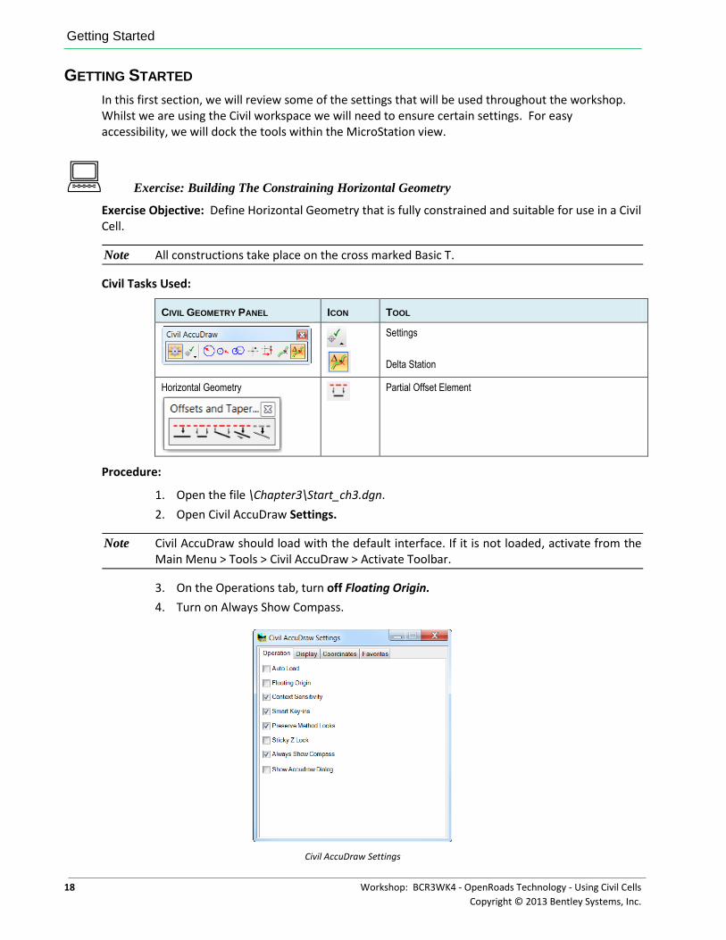
2. Open Civil AccuDraw Settings.
Note Civil AccuDraw should load with the default interface. If it is not loaded, activate from the Main Menu > Tools > Civil AccuDraw > Activate Toolbar.
3. On the Operations tab, turn off Floating Origin.
4. Turn on Always Show Compass.
Civil AccuDraw Settings
Getting Started
Workshop: BCR3WK4 - OpenRoads Technology - Using Civil Cells 19
Copyright © 2013 Bentley Systems, Inc.
Note If we leave floating origin enabled then each data point we use will relocate the origin to that new location and will potentially require redefinition to maintain the design intent.
5. Close the Civil AccuDraw settings panel.
6. Enable Civil AccuDraw with Delta Station-Offset.
Civil AccuDraw
7. On the Features Definition Toggle Bar, enable Use Active Feature Definition.
8. Set the Feature Definition to Linear>Roadway>Road_Centerline.
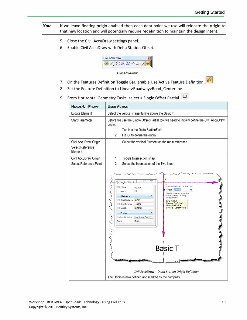
9. From Horizontal Geometry Tasks, select > Single Offset Partial.
HEADS-UP PROMPT USER ACTION
Locate Element Select the vertical magenta line above the Basic T.
Start Parameter Before we use the Single Offset Partial tool we need to initially define the Civil AccuDraw origin.
1. Tab into the Delta StationField
2. Hit ‘O’ to define the origin
Civil AccuDraw Origin
Select Reference Element
1. Select the vertical Element as the main reference
Civil AccuDraw Origin
Select Reference Point
1. Toggle Intersection snap
2. Select the intersection of the Two lines
Civil AccuDraw – Delta Station Origin Definition
The Origin is now defined and marked by the compass.
Getting Started
20 Workshop: BCR3WK4 - OpenRoads Technology - Using Civil Cells
Copyright © 2013 Bentley Systems, Inc.
Start Parameter 1. Tab into the Delta Station Field
2. Enter a value of 0 to lock to the intersection (notice the padlock next to the value to show it is locked in).
3. Tab to the offset.
4. Enter a value of 0 to again lock to the intersection.
5. Left Click / data point to accept the value and lock in the Start Parameter.
Civil AccuDraw – Delta Station Start Point Definition
End Parameter 1. Tab into the Delta Station Field
2. Enter a value of 30 (Delta Station follow direction of the element and so is fully constrained, simply entering a length does not constrain direction suitable for reversal situation although simply defining length is valid in some constructions).
Civil AccuDraw – Delta Station End Point Definition
(As we are using single offset locking the offset is not required and has no effect here).
3. Left Click / data point to accept the value the End Parameter and to create the required control geometry for the Civil Cell.
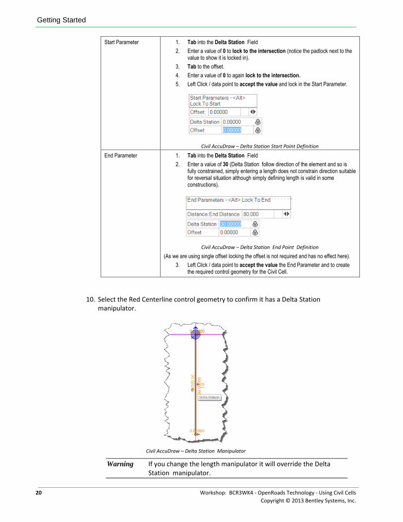
10. Select the Red Centerline control geometry to confirm it has a Delta Station manipulator.
Civil AccuDraw – Delta Station Manipulator
Warning If you change the length manipulator it will override the Delta Station manipulator.
Getting Started
Workshop: BCR3WK4 - OpenRoads Technology - Using Civil Cells 21
Copyright © 2013 Bentley Systems, Inc.
Note This is an essential construction that forms the starting point for most civil cells. Take time to be confident in the use of Delta Station .
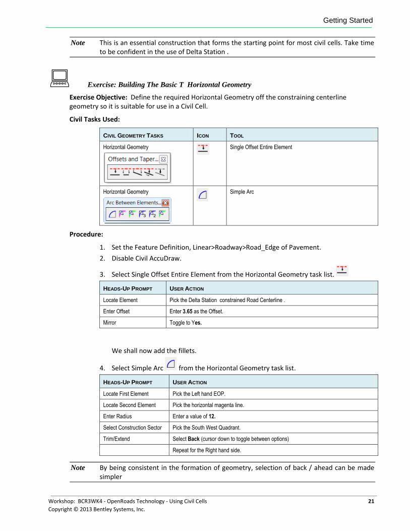
Exercise: Building The Basic T Horizontal Geometry
Exercise Objective: Define the required Horizontal Geometry off the constraining centerline geometry so it is suitable for use in a Civil Cell.
Civil Tasks Used:
CIVIL GEOMETRY TASKS ICON TOOL
Horizontal Geometry
Single Offset Entire Element
Horizontal Geometry
Simple Arc
Procedure:
1. Set the Feature Definition, Linear>Roadway>Road_Edge of Pavement.
2. Disable Civil AccuDraw.
3. Select Single Offset Entire Element from the Horizontal Geometry task list.
HEADS-UP PROMPT USER ACTION
Locate Element Pick the Delta Station constrained Road Centerline .
Enter Offset Enter 3.65 as the Offset.
Mirror Toggle to Yes.
We shall now add the fillets.
4. Select Simple Arc from the Horizontal Geometry task list.
HEADS-UP PROMPT USER ACTION
Locate First Element Pick the Left hand EOP.
Locate Second Element Pick the horizontal magenta line.
Enter Radius Enter a value of 12.
Select Construction Sector Pick the South West Quadrant.
Trim/Extend Select Back (cursor down to toggle between options)
Repeat for the Right hand side.
Note By being consistent in the formation of geometry, selection of back / ahead can be made simpler
Chapter Summary
22 Workshop: BCR3WK4 - OpenRoads Technology - Using Civil Cells
Copyright © 2013 Bentley Systems, Inc.
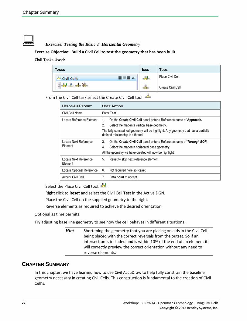
Exercise: Testing the Basic T Horizontal Geometry
Exercise Objective: Build a Civil Cell to test the geometry that has been built.
Civil Tasks Used:
TASKS ICON TOOL
Place Civil Cell
Create Civil Cell
From the Civil Cell task select the Create Civil Cell tool.
HEADS-UP PROMPT USER ACTION
Civil Cell Name Enter Test.
Locate Reference Element 1. On the Create Civil Cell panel enter a Reference name of Approach.
2. Select the magenta vertical base geometry.
The fully constrained geometry will be highlight. Any geometry that has a partially defined relationship is dithered.
Locate Next Reference Element
3. On the Create Civil Cell panel enter a Reference name of Through EOP.
4. Select the magenta horizontal base geometry.
All the geometry we have created will now be highlight.
Locate Next Reference Element
5. Reset to skip next reference element.
Locate Optional Reference 6. Not required here so Reset.
Accept Civil Cell 7. Data point to accept.
Select the Place Civil Cell tool. .
Right click to Reset and select the Civil Cell Test in the Active DGN.
Place the Civil Cell on the supplied geometry to the right.
Reverse elements as required to achieve the desired orientation.
Optional as time permits.
Try adjusting base line geometry to see how the cell behaves in different situations.
Hint Shortening the geometry that you are placing on aids in the Civil Cell being placed with the correct reversals from the outset. So if an intersection is included and is within 10% of the end of an element it will correctly preview the correct orientation without any need to reverse elements.
CHAPTER SUMMARY
In this chapter, we have learned how to use Civil AccuDraw to help fully constrain the baseline geometry necessary in creating Civil Cells. This construction is fundamental to the creation of Civil Cell’s.
Workshop: BCR3WK4 - OpenRoads Technology - Using Civil Cells 23
Copyright © 2013 Bentley Systems, Inc.
Chapter 4: Essential Vertical Constructions
OVERVIEW
In this session we will introduce the basic concepts for the use of vertical geometry in Civil Cell’s. We will create all the vertical geometry required to extend progress the basic T junction used in the previous chapter and will build and test 3D civil cell.
Many of the steps will be a repeat of the previous. These will not be repeated verbatim in this chapter but will refer back to the previous chapters methodology for certain processes.
PROJECT DESCRIPTION
We will continue on from the previous chapter evolving the geometry by adding vertical constraints. As in the previous workshop chapter, we will continue to use a very basic DGN file with some idealistic base geometry representing the real geometry that the civil cell will be applied to.
As stated in previous chapters, when building Civil Cells, we are using simplistic geometry to build and test on, not real world geometry. This approach makes life easier since the cells are quicker to build and simpler to understand and we consider the rules we are building into them and evaluating to ensure they work in future situations.
For the purpose of this chapter, some simple profiles have been added to the test base geometry. However we will also add this simple vertical to the base geometry to demonstrate the process. These simple profiles can later be redefined if further testing of alternative situations is needed.
This chapter will use the following Civil Tasks and Toolbars.
Horizontal Geometry
Partial Offset Element
Vertical Geometry
Profile by Slope from Element
Profile by Constant Elevation
Quick Profile Transition
Civil Cells
Create Civil Cell
Place Civil Cell
Project Description
24 Workshop: BCR3WK4 - OpenRoads Technology - Using Civil Cells
Copyright © 2013 Bentley Systems, Inc.
Features Definition Toggle Bar
Use Active Feature
Create 3D Automatically
Features Definition Toggle Bar with Create 3D automatically enabled
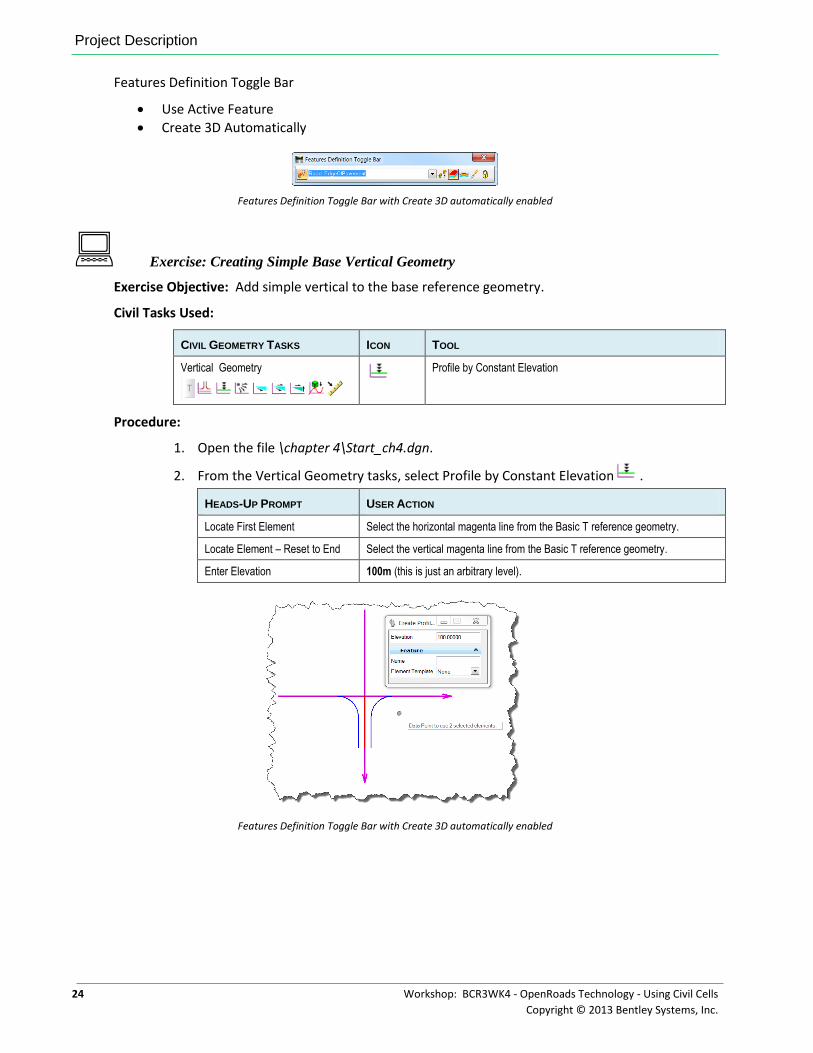
Exercise: Creating Simple Base Vertical Geometry
Exercise Objective: Add simple vertical to the base reference geometry.
Civil Tasks Used:
CIVIL GEOMETRY TASKS ICON TOOL
Vertical Geometry
Profile by Constant Elevation
Procedure:
1. Open the file \chapter 4\Start_ch4.dgn.
2. From the Vertical Geometry tasks, select Profile by Constant Elevation .
HEADS-UP PROMPT USER ACTION
Locate First Element Select the horizontal magenta line from the Basic T reference geometry.
Locate Element – Reset to End Select the vertical magenta line from the Basic T reference geometry.
Enter Elevation 100m (this is just an arbitrary level).
Features Definition Toggle Bar with Create 3D automatically enabled
Project Description
Workshop: BCR3WK4 - OpenRoads Technology - Using Civil Cells 25
Copyright © 2013 Bentley Systems, Inc.
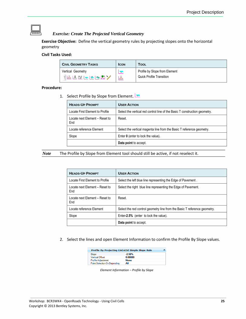
Exercise: Create The Projected Vertical Geometry
Exercise Objective: Define the vertical geometry rules by projecting slopes onto the horizontal geometry
Civil Tasks Used:
CIVIL GEOMETRY TASKS ICON TOOL
Vertical Geometry
Profile by Slope from Element
Quick Profile Transition
Procedure:
1. Select Profile by Slope from Element.
HEADS-UP PROMPT USER ACTION
Locate First Element to Profile Select the vertical red control line of the Basic T construction geometry.
Locate next Element – Reset to End
Reset.
Locate reference Element Select the vertical magenta line from the Basic T reference geometry.
Slope Enter 0 (enter to lock the value).
Data point to accept.
Note The Profile by Slope from Element tool should still be active, if not reselect it.
HEADS-UP PROMPT USER ACTION
Locate First Element to Profile Select the left blue line representing the Edge of Pavement .
Locate next Element – Reset to End
Select the right blue line representing the Edge of Pavement.
Locate next Element – Reset to End
Reset.
Locate reference Element Select the red control geometry line from the Basic T reference geometry.
Slope Enter-2.5% (enter to lock the value).
Data point to accept.
2. Select the lines and open Element Information to confirm the Profile By Slope values.
Element Information – Profile by Slope
Project Description
26 Workshop: BCR3WK4 - OpenRoads Technology - Using Civil Cells
Copyright © 2013 Bentley Systems, Inc.
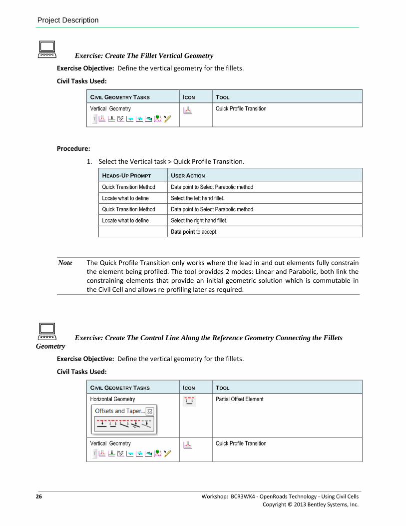
Exercise: Create The Fillet Vertical Geometry
Exercise Objective: Define the vertical geometry for the fillets.
Civil Tasks Used:
CIVIL GEOMETRY TASKS ICON TOOL
Vertical Geometry
Quick Profile Transition
Procedure:
1. Select the Vertical task > Quick Profile Transition.
HEADS-UP PROMPT USER ACTION
Quick Transition Method Data point to Select Parabolic method
Locate what to define Select the left hand fillet.
Quick Transition Method Data point to Select Parabolic method.
Locate what to define Select the right hand fillet.
Data point to accept.
Note The Quick Profile Transition only works where the lead in and out elements fully constrain the element being profiled. The tool provides 2 modes: Linear and Parabolic, both link the constraining elements that provide an initial geometric solution which is commutable in the Civil Cell and allows re-profiling later as required.
Exercise: Create The Control Line Along the Reference Geometry Connecting the Fillets
Geometry
Exercise Objective: Define the vertical geometry for the fillets.
Civil Tasks Used:
CIVIL GEOMETRY TASKS ICON TOOL
Horizontal Geometry
Partial Offset Element
Vertical Geometry
Quick Profile Transition
Chapter Summary
Workshop: BCR3WK4 - OpenRoads Technology - Using Civil Cells 27
Copyright © 2013 Bentley Systems, Inc.
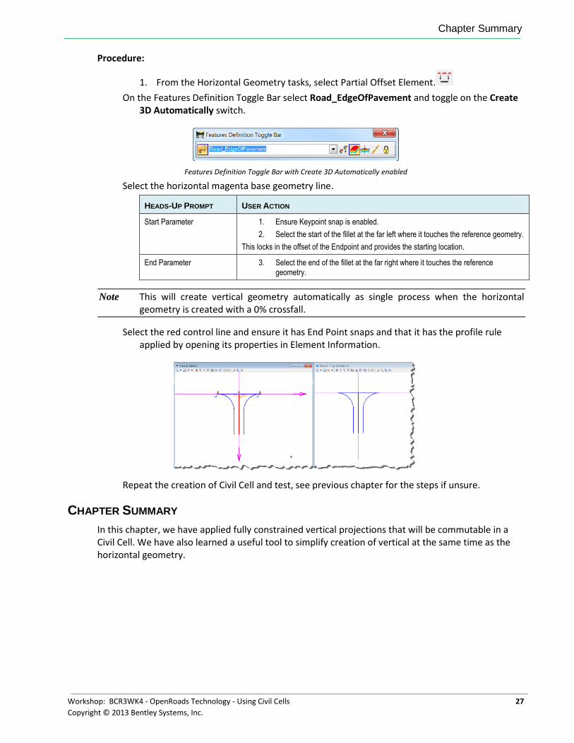
Procedure:
1. From the Horizontal Geometry tasks, select Partial Offset Element.
On the Features Definition Toggle Bar select Road_EdgeOfPavement and toggle on the Create 3D Automatically switch.
Features Definition Toggle Bar with Create 3D Automatically enabled
Select the horizontal magenta base geometry line.
HEADS-UP PROMPT USER ACTION
Start Parameter 1. Ensure Keypoint snap is enabled.
2. Select the start of the fillet at the far left where it touches the reference geometry.
This locks in the offset of the Endpoint and provides the starting location.
End Parameter 3. Select the end of the fillet at the far right where it touches the reference geometry.
Note This will create vertical geometry automatically as single process when the horizontal geometry is created with a 0% crossfall.
Select the red control line and ensure it has End Point snaps and that it has the profile rule applied by opening its properties in Element Information.
Repeat the creation of Civil Cell and test, see previous chapter for the steps if unsure.
CHAPTER SUMMARY
In this chapter, we have applied fully constrained vertical projections that will be commutable in a Civil Cell. We have also learned a useful tool to simplify creation of vertical at the same time as the horizontal geometry.

Chapter Summary
28 Workshop: BCR3WK4 - OpenRoads Technology - Using Civil Cells
Copyright © 2013 Bentley Systems, Inc.
This page left intentionally blank.
Workshop: BCR3WK4 - OpenRoads Technology - Using Civil Cells 29
Copyright © 2013 Bentley Systems, Inc.
Chapter 5: Building Terrains and Applying Surface Templates
OVERVIEW
In this session, we will continue to develop the Civil Cell by adding to the base geometry the required surface modeling to create the Basic T intersection.
Many of the steps will be a repeat of previous. These will not be repeated verbatim in this chapter but will refer back to the previous chapters methodology for certain processes.
PROJECT DESCRIPTION
We will continue on from the previous Chapter by creating a terrain from the ruled civil geometry. Civil Terrains can be ruled to graphical elements and react to geometric change dynamically. To ensure the terrains update correctly the underlying base geometry needs to be well formed and have been tested with base geometry modifications to ensure that the terrain will heal and reform following these changes.
As stated in previous chapters, when building Civil Cells we are using simplistic geometry to build and test on, not real world geometry. This approach makes life easier since the cells are quicker to build and simpler to understand and we consider the rules we are building into them and evaluating to ensure they work in future situations.
For the purpose of this chapter some simple profiles have been added to the test base geom. However we will also add this simple vertical to the base geometry to demonstrate the process. These simple profiles can later be redefined if further testing of alternative situations is needed.
This chapter will use the following Civil Tasks and Toolbars
Terrain Model
Create from Elements
Add Features
Change Feature Type (Optional)
3D Geometry
Apply Surface Template
Civil Cells
Create Civil Cell
Place Civil Cell
Project Description
30 Workshop: BCR3WK4 - OpenRoads Technology - Using Civil Cells
Copyright © 2013 Bentley Systems, Inc.
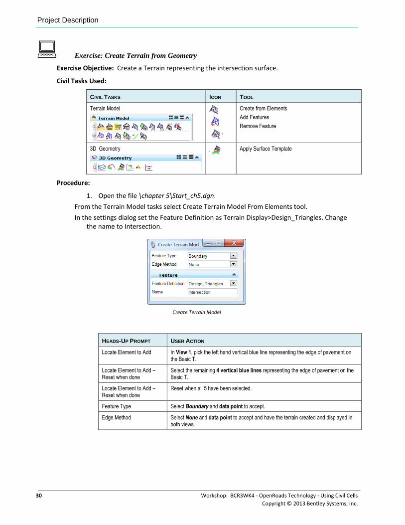
Exercise: Create Terrain from Geometry
Exercise Objective: Create a Terrain representing the intersection surface.
Civil Tasks Used:
CIVIL TASKS ICON TOOL
Terrain Model
Create from Elements
Add Features
Remove Feature
3D Geometry
Apply Surface Template
Procedure:
1. Open the file \chapter 5\Start_ch5.dgn.
From the Terrain Model tasks select Create Terrain Model From Elements tool.
In the settings dialog set the Feature Definition as Terrain Display>Design_Triangles. Change the name to Intersection.
Create Terrain Model
HEADS-UP PROMPT USER ACTION
Locate Element to Add In View 1, pick the left hand vertical blue line representing the edge of pavement on the Basic T.
Locate Element to Add – Reset when done
Select the remaining 4 vertical blue lines representing the edge of pavement on the Basic T.
Locate Element to Add – Reset when done
Reset when all 5 have been selected.
Feature Type Select Boundary and data point to accept.
Edge Method Select None and data point to accept and have the terrain created and displayed in both views.
Project Description
Workshop: BCR3WK4 - OpenRoads Technology - Using Civil Cells 31
Copyright © 2013 Bentley Systems, Inc.
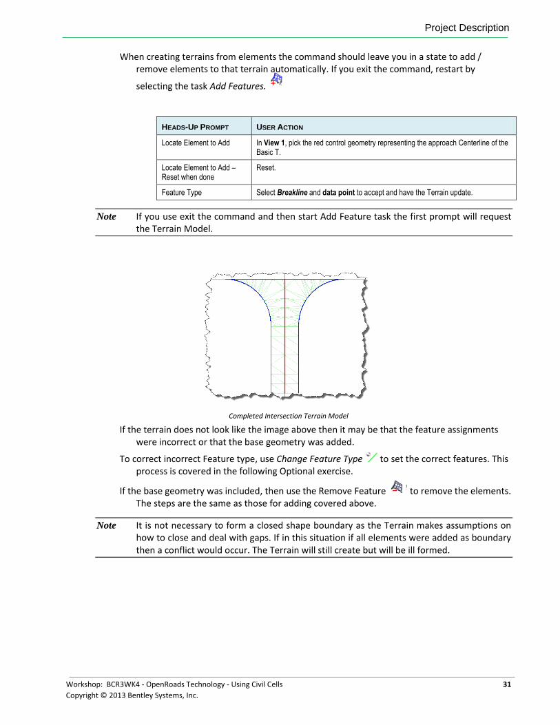
When creating terrains from elements the command should leave you in a state to add / remove elements to that terrain automatically. If you exit the command, restart by
selecting the task Add Features.
HEADS-UP PROMPT USER ACTION
Locate Element to Add In View 1, pick the red control geometry representing the approach Centerline of the Basic T.
Locate Element to Add – Reset when done
Reset.
Feature Type Select Breakline and data point to accept and have the Terrain update.
Note If you use exit the command and then start Add Feature task the first prompt will request the Terrain Model.
Completed Intersection Terrain Model
If the terrain does not look like the image above then it may be that the feature assignments were incorrect or that the base geometry was added.
To correct incorrect Feature type, use Change Feature Type to set the correct features. This process is covered in the following Optional exercise.
If the base geometry was included, then use the Remove Feature to remove the elements. The steps are the same as those for adding covered above.
Note It is not necessary to form a closed shape boundary as the Terrain makes assumptions on how to close and deal with gaps. If in this situation if all elements were added as boundary then a conflict would occur. The Terrain will still create but will be ill formed.
Project Description
32 Workshop: BCR3WK4 - OpenRoads Technology - Using Civil Cells
Copyright © 2013 Bentley Systems, Inc.
Optional Exercise: Modify Feature Types in the Terrain
Exercise Objective: Change Terrain feature types in to achieve the correct intersection surface.
Civil Tasks Used:
CIVIL TASKS ICON TOOL
Terrain Model
Change Feature Type
Procedure:
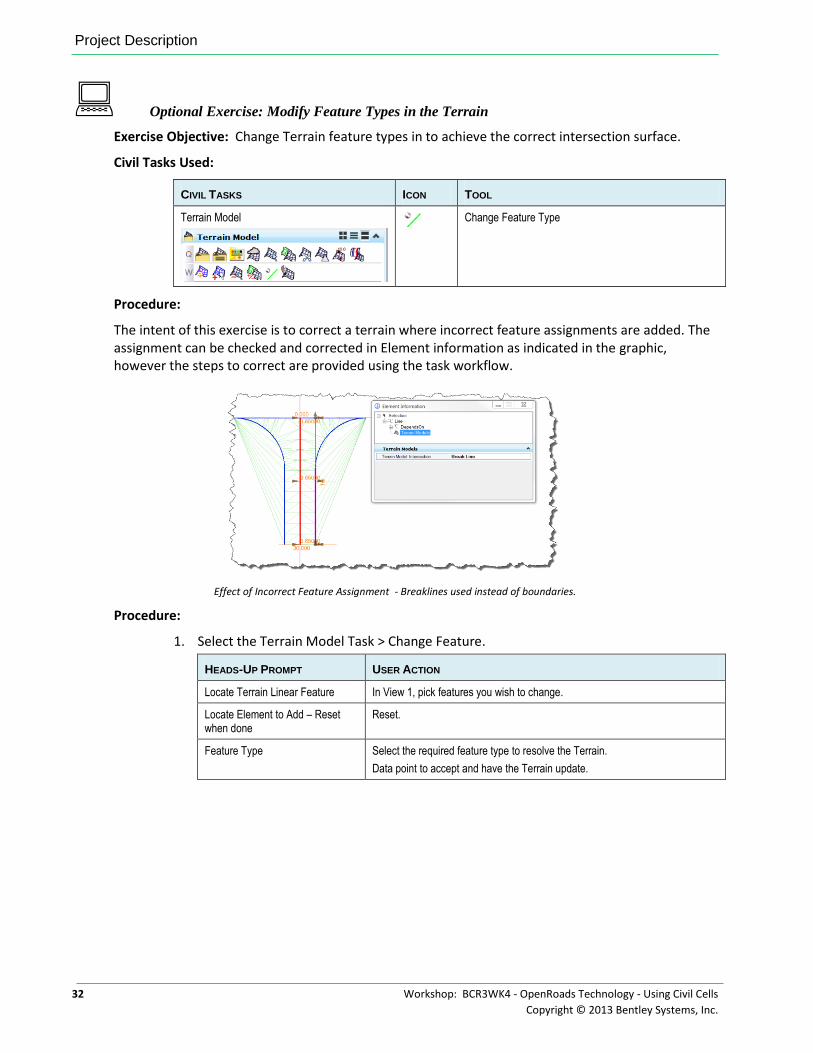
The intent of this exercise is to correct a terrain where incorrect feature assignments are added. The assignment can be checked and corrected in Element information as indicated in the graphic, however the steps to correct are provided using the task workflow.
Effect of Incorrect Feature Assignment - Breaklines used instead of boundaries.
Procedure:
1. Select the Terrain Model Task > Change Feature.
HEADS-UP PROMPT USER ACTION
Locate Terrain Linear Feature In View 1, pick features you wish to change.
Locate Element to Add – Reset when done
Reset.
Feature Type Select the required feature type to resolve the Terrain.
Data point to accept and have the Terrain update.
Project Description
Workshop: BCR3WK4 - OpenRoads Technology - Using Civil Cells 33
Copyright © 2013 Bentley Systems, Inc.
Exercise: Apply Surface Template to the Terrain
Exercise Objective: Apply a Surface Template to the Intersection Terrain.
Civil Tasks Used:
CIVIL TASKS ICON TOOL
3D Geometry
Apply Surface Template
Procedure:
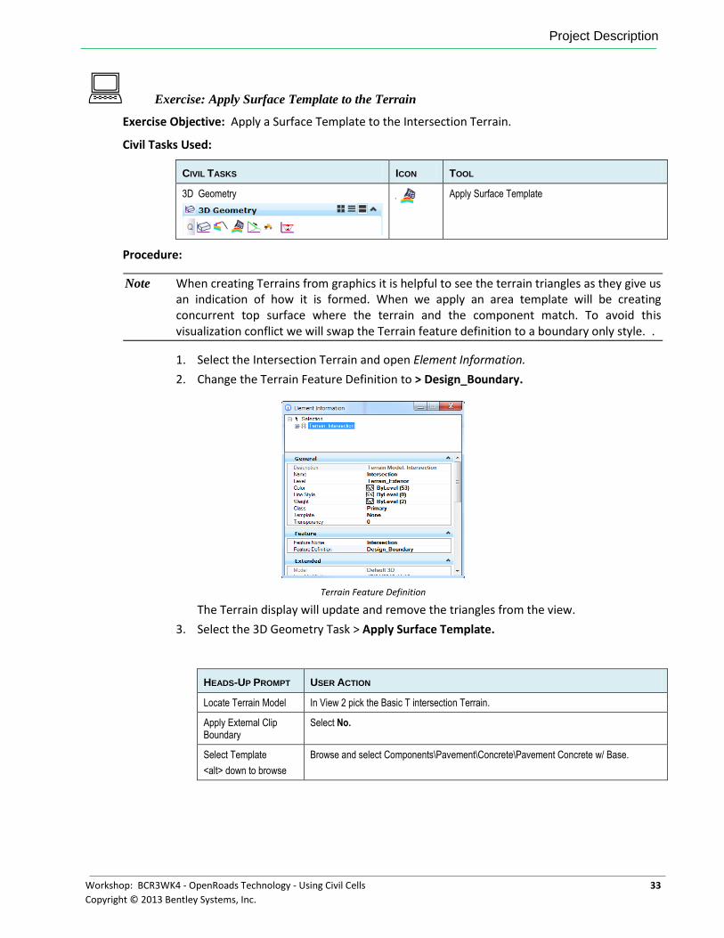
Note When creating Terrains from graphics it is helpful to see the terrain triangles as they give us an indication of how it is formed. When we apply an area template will be creating concurrent top surface where the terrain and the component match. To avoid this visualization conflict we will swap the Terrain feature definition to a boundary only style. .
1. Select the Intersection Terrain and open Element Information.
2. Change the Terrain Feature Definition to > Design_Boundary.
Terrain Feature Definition
The Terrain display will update and remove the triangles from the view.
3. Select the 3D Geometry Task > Apply Surface Template.
HEADS-UP PROMPT USER ACTION
Locate Terrain Model In View 2 pick the Basic T intersection Terrain.
Apply External Clip Boundary
Select No.
Select Template
<alt> down to browse
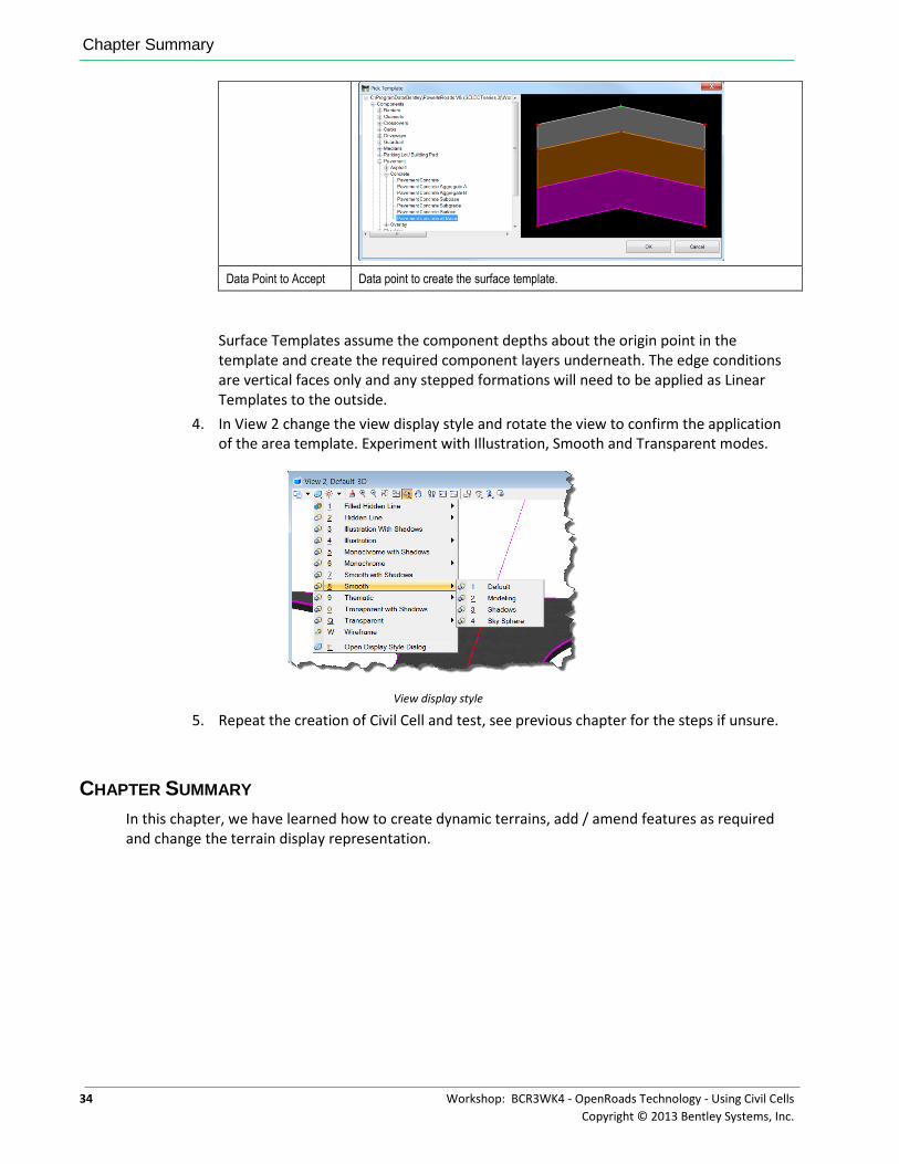
Browse and select Components\Pavement\Concrete\Pavement Concrete w/ Base.
Chapter Summary
34 Workshop: BCR3WK4 - OpenRoads Technology - Using Civil Cells
Copyright © 2013 Bentley Systems, Inc.
Data Point to Accept Data point to create the surface template.
Surface Templates assume the component depths about the origin point in the template and create the required component layers underneath. The edge conditions are vertical faces only and any stepped formations will need to be applied as Linear Templates to the outside.
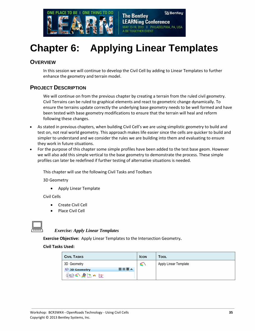
4. In View 2 change the view display style and rotate the view to confirm the application of the area template. Experiment with Illustration, Smooth and Transparent modes.
View display style
5. Repeat the creation of Civil Cell and test, see previous chapter for the steps if unsure.
CHAPTER SUMMARY
In this chapter, we have learned how to create dynamic terrains, add / amend features as required and change the terrain display representation.
Workshop: BCR3WK4 - OpenRoads Technology - Using Civil Cells 35
Copyright © 2013 Bentley Systems, Inc.
Chapter 6: Applying Linear Templates
OVERVIEW
In this session we will continue to develop the Civil Cell by adding to Linear Templates to further enhance the geometry and terrain model.
PROJECT DESCRIPTION
We will continue on from the previous chapter by creating a terrain from the ruled civil geometry. Civil Terrains can be ruled to graphical elements and react to geometric change dynamically. To ensure the terrains update correctly the underlying base geometry needs to be well formed and have been tested with base geometry modifications to ensure that the terrain will heal and reform following these changes.
As stated in previous chapters, when building Civil Cell’s we are using simplistic geometry to build and test on, not real world geometry. This approach makes life easier since the cells are quicker to build and simpler to understand and we consider the rules we are building into them and evaluating to ensure they work in future situations.
For the purpose of this chapter some simple profiles have been added to the test base geom. However we will also add this simple vertical to the base geometry to demonstrate the process. These simple profiles can later be redefined if further testing of alternative situations is needed.
This chapter will use the following Civil Tasks and Toolbars
3D Geometry
Apply Linear Template
Civil Cells
Create Civil Cell
Place Civil Cell
Exercise: Apply Linear Templates
Exercise Objective: Apply Linear Templates to the Intersection Geometry.
Civil Tasks Used:
CIVIL TASKS ICON TOOL
3D Geometry
Apply Linear Template
Project Description
36 Workshop: BCR3WK4 - OpenRoads Technology - Using Civil Cells
Copyright © 2013 Bentley Systems, Inc.
Procedure:
1. Open the file \chapter 6\Start_ch6.dgn.
Before we start it will aid us in selections to simplify the 2D model view.
2. With View 1 active Select References and turn off display for the attached model (Default-3D).
3. From the 3D Geometry tasks select Apply Linear Template.
4. Start applying the Linear Template to the blue vertical line representing the left hand edge of pavement in the Basic T intersection.
HEADS-UP PROMPT USER ACTION
Locate Element to apply template
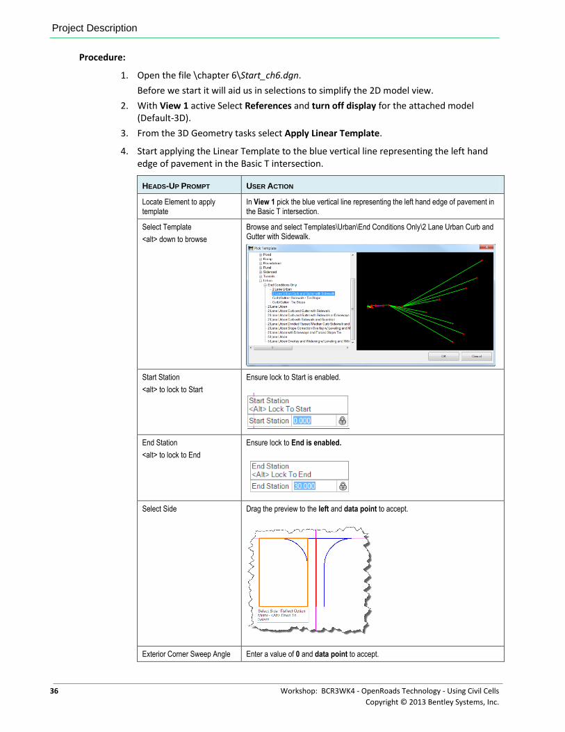
In View 1 pick the blue vertical line representing the left hand edge of pavement in the Basic T intersection.
Select Template
<alt> down to browse
Browse and select Templates\Urban\End Conditions Only\2 Lane Urban Curb and Gutter with Sidewalk.
Start Station
<alt> to lock to Start
Ensure lock to Start is enabled.
End Station
<alt> to lock to End
Ensure lock to End is enabled.
Select Side Drag the preview to the left and data point to accept.
Exterior Corner Sweep Angle Enter a value of 0 and data point to accept.
Chapter Summary
Workshop: BCR3WK4 - OpenRoads Technology - Using Civil Cells 37
Copyright © 2013 Bentley Systems, Inc.
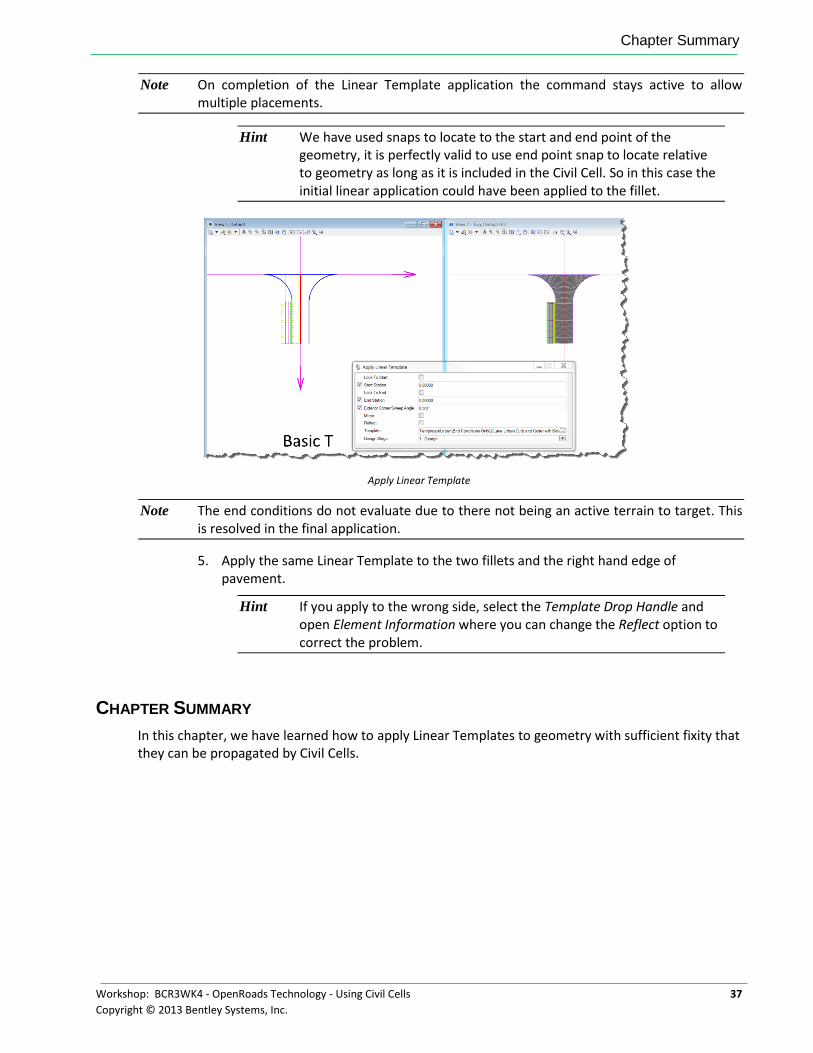
Note On completion of the Linear Template application the command stays active to allow multiple placements.
Hint We have used snaps to locate to the start and end point of the geometry, it is perfectly valid to use end point snap to locate relative to geometry as long as it is included in the Civil Cell. So in this case the initial linear application could have been applied to the fillet.
Apply Linear Template
Note The end conditions do not evaluate due to there not being an active terrain to target. This is resolved in the final application.
5. Apply the same Linear Template to the two fillets and the right hand edge of pavement.
Hint If you apply to the wrong side, select the Template Drop Handle and open Element Information where you can change the Reflect option to correct the problem.
CHAPTER SUMMARY
In this chapter, we have learned how to apply Linear Templates to geometry with sufficient fixity that they can be propagated by Civil Cells.

Chapter Summary
38 Workshop: BCR3WK4 - OpenRoads Technology - Using Civil Cells
Copyright © 2013 Bentley Systems, Inc.
This page left intentionally blank.
Workshop: BCR3WK4 - OpenRoads Technology - Using Civil Cells 39
Copyright © 2013 Bentley Systems, Inc.
Chapter 7: Creating and Managing Civil Cells
OVERVIEW
In this session we will create the Civil Cell and prepare it for use in production.
PROJECT DESCRIPTION
We will continue on from the previous Chapter by creating a terrain from the ruled civil geometry. Civil Terrains can be ruled to graphical elements and react to geometric change dynamically. To ensure the terrains update correctly the underlying base geometry needs to be well formed and have been tested with base geometry modifications to ensure that the terrain will heal and reform following these changes.
As stated in previous chapters, when building Civil Cell’s we are using simplistic geometry to build and test on, not real world geometry. This approach makes life easier since the cells are quicker to build and simpler to understand and we consider the rules we are building into them and evaluating to ensure they work in future situations.
For the purpose of this chapter some simple profiles have been added to the test base geom. However we will also add this simple vertical to the base geometry to demonstrate the process. These simple profiles can later be redefined if further testing of alternative situations is needed.
This chapter will use the following Civil Tasks and Toolbars.
Civil Cells
Create Civil Cell
Place Civil Cell
Process Civil Cell
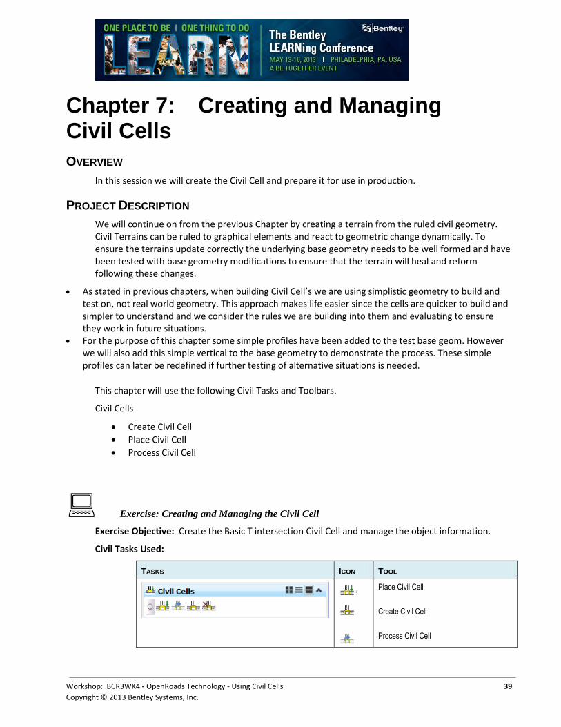
Exercise: Creating and Managing the Civil Cell
Exercise Objective: Create the Basic T intersection Civil Cell and manage the object information.
Civil Tasks Used:
TASKS ICON TOOL
Place Civil Cell
Create Civil Cell
Process Civil Cell
Project Description
40 Workshop: BCR3WK4 - OpenRoads Technology - Using Civil Cells
Copyright © 2013 Bentley Systems, Inc.
Procedure:
1. Open the file \chapter7\Start_ch7.dgn.
We have previously created Civil Cells in testing but this time we need to give consideration towards creating for production purposes.
2. From the Civil Cell task select the Create Civil Cell tool.
HEADS-UP PROMPT USER ACTION
Civil Cell Name Enter Basic T Intersection.
Locate Reference Element 1. On the Create Civil Cell panel enter a Reference name of ‘Approach.’
2. Select the magenta vertical base geometry.
The fully constrained geometry will be highlight. Any geometry that has a partially defined relationship is dithered.
Locate Next Reference Element
3. On the Create Civil Cell panel enter a Reference name of ‘Through EOP’
4. Select the magenta horizontal base geometry.
All the geometry we have created will now be highlight.
Locate Next Reference Element
5. Reset to skip next reference element.
Locate Optional Reference 6. Not required here so Reset.
Accept Civil Cell 7. Data point to accept.
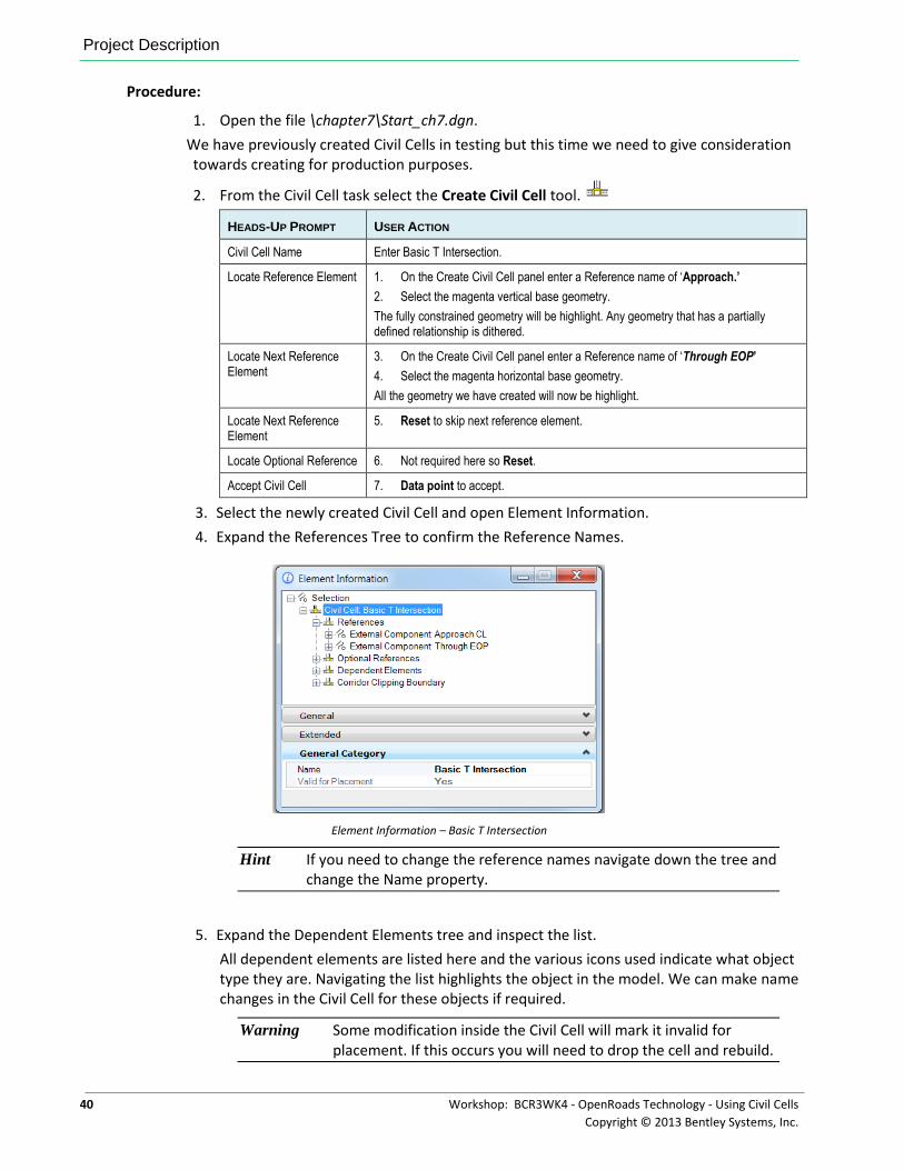
3. Select the newly created Civil Cell and open Element Information.
4. Expand the References Tree to confirm the Reference Names.
Element Information – Basic T Intersection
Hint If you need to change the reference names navigate down the tree and change the Name property.
5. Expand the Dependent Elements tree and inspect the list.
All dependent elements are listed here and the various icons used indicate what object type they are. Navigating the list highlights the object in the model. We can make name changes in the Civil Cell for these objects if required.
Warning Some modification inside the Civil Cell will mark it invalid for placement. If this occurs you will need to drop the cell and rebuild.
Chapter Summary
Workshop: BCR3WK4 - OpenRoads Technology - Using Civil Cells 41
Copyright © 2013 Bentley Systems, Inc.
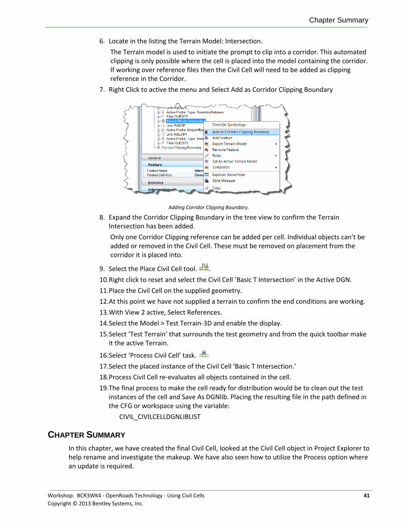
6. Locate in the listing the Terrain Model: Intersection.
The Terrain model is used to initiate the prompt to clip into a corridor. This automated clipping is only possible where the cell is placed into the model containing the corridor. If working over reference files then the Civil Cell will need to be added as clipping reference in the Corridor.
7. Right Click to active the menu and Select Add as Corridor Clipping Boundary
Adding Corridor Clipping Boundary.
8. Expand the Corridor Clipping Boundary in the tree view to confirm the Terrain Intersection has been added.
Only one Corridor Clipping reference can be added per cell. Individual objects can’t be added or removed in the Civil Cell. These must be removed on placement from the corridor it is placed into.
9. Select the Place Civil Cell tool. .
10. Right click to reset and select the Civil Cell ‘Basic T Intersection’ in the Active DGN.
11. Place the Civil Cell on the supplied geometry.
12. At this point we have not supplied a terrain to confirm the end conditions are working.
13. With View 2 active, Select References.
14. Select the Model > Test Terrain-3D and enable the display.
15. Select ‘Test Terrain’ that surrounds the test geometry and from the quick toolbar make it the active Terrain.
16. Select ‘Process Civil Cell’ task.
17. Select the placed instance of the Civil Cell ‘Basic T Intersection.’
18. Process Civil Cell re-evaluates all objects contained in the cell.
19. The final process to make the cell ready for distribution would be to clean out the test instances of the cell and Save As DGNlib. Placing the resulting file in the path defined in the CFG or workspace using the variable:
CIVIL_CIVILCELLDGNLIBLIST
CHAPTER SUMMARY
In this chapter, we have created the final Civil Cell, looked at the Civil Cell object in Project Explorer to help rename and investigate the makeup. We have also seen how to utilize the Process option where an update is required.

Chapter Summary
42 Workshop: BCR3WK4 - OpenRoads Technology - Using Civil Cells
Copyright © 2013 Bentley Systems, Inc.
This page left intentionally blank.

Workshop: BCR3WK4 - OpenRoads Technology - Using Civil Cells 43
Copyright © 2013 Bentley Systems, Inc.
Appendix A: Civil Cell Commands
CIVIL CELL COMMANDS
TOOL DESCRIPTION
Place Activates the browser to select the civil cell to be placed. Civil cells can be selected from the active DGN’s graphics, or from the browser that provides a schematic preview of available civil cells from all design models in the current DGN, or via the currently defined configuration.
Drop
Activates the drop command and targets civil cells.
The standard MicroStation Drop command works on civil cells, but selection is dependent on element priority in the model and may require element cycling to select the civil cell.
Process Reprocesses all Linear Templates and templates for the selected civil cell. This may be necessary where the active terrain has been changed or where reference file interaction needs to be refreshed.
Delete
Activates the drop command and targets civil cells.
The standard MicroStation Delete command works but you will need to cycle through the available elements under the cursor to select the Civil Cell.
Create Activates the command. Prompts you to name the new civil cell and select reference elements. The dependent elements are identified and highlighted for verification.

Civil Cell Commands
44 Workshop: BCR3WK4 - OpenRoads Technology - Using Civil Cells
Copyright © 2013 Bentley Systems, Inc.
This page left intentionally blank.

Workshop: BCR3WK4 - OpenRoads Technology - Using Civil Cells 45
Copyright © 2013 Bentley Systems, Inc.
Appendix B: Best Practices
OVERVIEW
To create the most flexible civil cells - the ones that will place correctly in as many situations as possible - there are several things to consider. Civil cells are, at a basic level, a collection of rules which are used to create the new elements. It therefore follows that the rules need to be constructed in such a way that they will always evaluate correctly when the civil cell is placed.
CREATING CIVIL CELLS
While it is possible to capture a Civil Cell in situ this can generate more problems downstream as it may not be well formed or suitable for application elsewhere. When it is identified that a Civil Cell will be of use consider creating independently, it is advisable to take the time to plan ahead it’s construction, possible applications and modifications before creating and testing the Civil Cell.
USING A DGNLIB
If you want to be able to reuse your civil cell in different designs, create it in a DGNLib, then put it in a location that MicroStation will read when it starts up. This ensures that the civil cell will always be available.
If you intend to create a lot of civil cells, it may be worth organizing them so that you have a DGNLib for each type - for example one for junctions, and another for ramps. Each DGNlib can contain many Civil Cells in a single or multiple models. One reason for doing this is that it makes navigating to an individual civil cell easier as initial selection will be on the type.
If you have already created some civil elements in a DGN that you would like to be able to share in a DGNLib, then you can use the following process to extract the Civil Cell:
1. Create a Civil Cell in the DGN.
2. Open the DGNLib that you want to contain the Civil Cell.
3. Reference the DGN which contains the Civil Cell in to the DGNLib.
4. Create elements in the DGNLib to use as reference elements.
5. Use the Place Civil Cell command to place the civil cell on these reference elements.
6. Drop the Civil Cell and remove any geometry that is not required.
7. Rename elements and objects suitable for distribution.
8. Build the Civil Cell.
The DGNLib will now contain the civil cell, and it can be shared as required.
Appendix B: Best Practices
46 Workshop: BCR3WK4 - OpenRoads Technology - Using Civil Cells
Copyright © 2013 Bentley Systems, Inc.
CIVIL CELLS CONTENT
Keep the content to a minimum and chose suitable reference elements.
Consider what the civil cell really needs to contain, and include only the minimum. For example, if you are creating a civil cell for a junction, it is quite likely that it only needs to contain one reference element to represent the road edge of the main road. It should not include any corridors or other elements from the through road, because they do not belong in a junction, and they will cause extra processing. You cannot delete dependent elements in a civil cell, so any extra elements have to be deleted once the civil cell has been placed. Similarly, if the pavement construction depth changes often, then it might be easier to apply the template to model the layers after the civil cell has been placed than delete the surface template and apply a different one. If the construction depths are fairly standard though a surface template in the civil cell could be the most efficient procedure.
CIVIL CELL NAMING
Consider the naming used for all elements contained in the Civil Cell as well as appropriate prompts for reference elements. These Civil Cells when deployed will be used by others who may not know the Civil Cell as intimately as the creator.
The Civil Cell itself provides a container that provides unique element naming and so a Terrain called Intersection can reside multiple times in the same DGN model inside different Civil Cells. When Civil Cells are dropped the Element names contained therein are renamed to the next available name by appending an index number on the end of the name.
START / END LOCATIONS AND APPROPRIATE SNAPS
If you want to create an element in a civil cell that is a certain length, you could specify the start and end stations as Delta Stations using Civil AccuDraw relative to a known location - typically an intersection of two elements.
If a civil cell is created at absolute stations these may not exist in the recipient geometry and so the civil cell will not place.
Typically good constraining snaps - Endpoint, Intersection, Perpendicular, Tangent, Centre, Midpoint
Consider the snaps carefully and how they will be used at application time. An intersection snap may be ‘vague’ on placement if the geometry one element or both are approaching infinity – reverse transition is a good example.
Appendix B: Best Practices
Workshop: BCR3WK4 - OpenRoads Technology - Using Civil Cells 47
Copyright © 2013 Bentley Systems, Inc.
USING POINTS
A 2D point can be used to locate a civil cell. In the case of an island for a pedestrian crossing for example, where the two sides of the island are parallel to a reference element, you want to be able to place it at any location along the reference element. This means that you should not specify start and end stations when you create the two sides because they would be stored in the civil cell, and it would always be placed at these stations. A better technique is to place a point, then place the elements to form the island relative to it. For example, create the offset transition elements for the sides of the island using offsets from the reference element, but define the start point by snapping to the point, and define the end point using a length. Now select the point and move it, and the two sides of the island will follow. When you create the civil cell, define the point as a reference element, so that you are prompted to select it when you place the civil cell. You do not have to create a point to do this, you can use a snap, or define the location of the point using Civil AccuDraw, or just use a data point, which means that you have lots of flexibility when defining the location.
There are other types of constructions that would also benefit from this technique - bus stops, traffic calming features, and merging / diverging ramps being just a few examples.
A 3D point can be used to achieve two objectives, because it can be used to not only locate a civil cell, but define elevations for it as well. In the case of a turning head for example, the geometry might consist of a circle, with two fillets to tie the turning head in to the end of the road. In this case, a point can be used to locate the centre of the circle, and if it is 3D, it can also be used to apply elevations to the circle. When the civil cell is placed, Civil AccuDraw can be used to snap to the profile of a suitable element, such as the centreline of the road for example, or a terrain model.
CIVIL ACCUDRAW
Civil AccuDraw provides the geometric constructions required to create fully constrained geometry in civil cells. It can constrain points using two ordinates which are relative to the elements they were constructed from, such as a distance or an offset constraint. An example of where this technique is useful is in creating a turn lane for an intersection, where you want the length to be from the intersection of the two road centrelines, for a certain distance. In this situation, the Delta Station option is likely to give the most flexible solution.
TESTING CIVIL CELLS
As you are creating civil cells test the geometric rules that will be captured. Once you have created all of the elements that you want to be in the civil cell, but before you create the civil cell itself, it is worthwhile thoroughly testing that the elements all react correctly to multiple changes. This can be done by moving the reference elements, and checking that all of the dependent elements also move. If any elements do not update correctly then this needs to be resolved before the civil cell is created.
USE OF CORRIDORS AND LINEAR TEMPLATES IN CIVIL CELL
Corridors and Linear Templates can be used in Civil Cell but the recommendation is keep the implementation simple. When creating Civil Cells, the process evaluates objects to determine if they have sufficient fixity will not allow inclusion of anything that does not meet the simple criteria.
In addition making changes inside an existing Civil Cell to Corridors and Linear Templates will render the Civil Cell as not suitable for placement. In these cases Drop the Civil Cell and rebuild to re-evaluate the content.

Appendix B: Best Practices
48 Workshop: BCR3WK4 - OpenRoads Technology - Using Civil Cells
Copyright © 2013 Bentley Systems, Inc.
CORRIDOR
OBJECT REFERENCED ENTITY STATION
RANGE
APPLIES
VALID IN CC
Template Drop
None YES YES if ruled including range (Start / end) or Civil AccuDraw > Delta Station
Point Control
Any one of :-
Plan Entity, Profile Entity, Corridor, Reference Feature, Superelevation, Feature Definition
YES YES if ruled including range (Start / end) or Civil AccuDraw > Delta Station
Curve Widening
None YES YES if ruled including range (Start / end) or Civil AccuDraw > Delta Station
Target Aliases
Referenced entity are not carried over
YES NO
Secondary Alignment
Plan Entity YES YES if ruled including range (Start / end) or Civil AccuDraw > Delta Station
Specific Profile
Profile Entity (cannot be external) NO NO
Key Station Distance Along Parameter NO YES if ruled including range (Start / end) or Civil AccuDraw > Delta Station or add afterwards
End Condition Exception
None YES YES if ruled including range (Start / end) or Civil AccuDraw > Delta Station - best practice add afterwards
Parametric Constraint
None YES YES if ruled including range (Start / end) or Civil AccuDraw > Delta Station - best practice add afterwards
For a complete and up-to-date listing of Best Practices refer to the OpenRoads website.
http://ftp2.bentley.com/dist/collateral/docs/bentley_civil_community_program/Best%20Practices_publish.pdf

Learning Paths
Workshop: BCR3WK4 - OpenRoads Technology - Using Civil Cells 49
Copyright © 2013 Bentley Systems, Inc.
Learning Paths All of our training through Bentley is accessible via learning paths, ready-made training plans that provide the recommended progression of skills training for a product, solution, job role, or experience level.
In developing your team, you can choose from Bentley-recommended learning paths or configure your own to meet your team’s specific needs.
Learning paths help us:
Develop our internal talent pool
Make our employees more productive
Prioritize learning topics by what is important to us as a company
Reinforce our corporate culture of continuous learning

Learning Paths
50 Workshop: BCR3WK4 - OpenRoads Technology - Using Civil Cells
Copyright © 2013 Bentley Systems, Inc.
This page left intentionally blank.
Workshop: BCR3WK4 - OpenRoads Technology - Using Civil Cells 51
Copyright © 2013 Bentley Systems, Inc.
Assessment
1. Civil Cells must be placed on 2D geometry ?
Answer… True
2. Civil Cells be defined to automatically clip corridors ?
Answer… True
3. Can Civil Cells be placed on geometry supplied by a reference file ?
Answer… True
4. Can Civil Cells replace the engineer ?
Answer… False

Assessment
52 Workshop: BCR3WK4 - OpenRoads Technology - Using Civil Cells
Copyright © 2013 Bentley Systems, Inc.
This page left intentionally blank.
Workshop: BCR3WK4 - OpenRoads Technology - Using Civil Cells 53
Copyright © 2013 Bentley Systems, Inc.
Glossary
2D Point Feature Contains no elevation (Z). 2D Point Features are defined and stored in plan model.
3D Geometry 3D geometry is created in 3D model by mathematically combining the horizontal and vertical geometry to create 3D elements. These 3D geometry elements in turn define a design model.
3D Model This is created and managed automatically. User can interact with it but this is not usually required. The mathematical combination of Plan Geometry and Profile Geometry is stored in the 3D model.
3D Point Feature 3D points can be defined in plan model or 3D model. They are stored in 3D model but represented in both plan and 3D.
Active Object The current object to which is added all geometry which is created.
Active Profile Of the multiple possible profiles for an element, the active profile is the one used for design. The active profile is combined with the horizontal geometry to build a 3D element which is used in the 3D model.
Active Terrain Model
One terrain model can be designated as “Active”. The active terrain model is the one used to display “existing ground”; in other words the one which displays automatically in a profile model when it is opened. The active terrain model is also the one which is targeted by side slopes unless the template defines a different target by name.
ALG A legacy (proprietary) InRoads file containing coordinate geometry information, superelevation, and alignment information for a specific geometry project.
Alignment A linear feature which serves the special purpose of defining the centerline or baseline of a roadway.
Apply Linear Template
Applies a corridor template along a feature while hiding some of the complexity of creating a corridor.
Apply Surface Template
Applies a corridor template to a terrain model for the purpose of creating components (such as pavement layers) under the terrain model.
Arc Definition Curve definition method generally used in roadway applications. The radius R is used to define the curve and is defined by the equation R=5729.58/D where the degree of curvature D is the central angle subtended by a 100-foot arc. Set in the Design File Settings > Civil Formatting under Radius Settings. See also Chord Definition.
Aspect An angular measure of the direction that the face of a surface is oriented. The format of the value is dependent on angular settings In the DGN file.
Base Geometry In many instances the geometry element will be trimmed. The original (or base), untrimmed element is always preserved as it is the storage for the rule.
Glossary
54 Workshop: BCR3WK4 - OpenRoads Technology - Using Civil Cells
Copyright © 2013 Bentley Systems, Inc.
Boundary (Terrain Model)
Used to constrain the external boundary of the terrain model. No triangles are created outside the boundary. In addition, any point data outside the boundary is ignored.
Break Line A surface feature consisting of a collection of spatial coordinates that have an implied linear relationship. No triangle side (in the triangulated surface) can cross over a break line.
Break Void A closed area of missing or obscured data that uses the elevations of each vertex, while the void lines between successive void coordinates are inserted as break lines. Therefore, break voids change the slope and elevations of the TIN surface.
Cardinal Points One of the points used to define the geometry of an alignment. Cardinal points include PC, PT, PI, and CC points for horizontal geometry and VPC, VPI and VPT for vertical geometry.
Centroid (triangle) Geometric center of a triangle in a terrain model.
Chord Definition Curve definition method generally used in railway applications. The radius R is used to define the curve, and is defined by the equation R=50/SIN(0.5*D) where the degree of curvature D is the central angle subtended by a 100-foot chord. See also Arc Definition.
Civil Cell Used as a mechanism to preconfigure commonly used complex geometric layouts. These layouts will commonly be stored in DGNLIB files for reuse across multiple projects but it is possible and sometimes useful to store directly in an active DGN file for use in that single location. The civil cell will contain horizontal geometry and can also contain the vertical geometry.
Civil Message Center
Used to display a continuous updating log of Civil messages, including warnings and errors. As errors and warnings are resolved, they are removed from the list. New messages are added whenever the conditions warrant. Most messages relate to civil geometry, superelevation, and corridor modeling.
Civil Template A civil design concept used most often for corridor modeling but also has other applications. The Civil Template defines the cross-sectional shape of the object being modeled. This cross-section is then “extruded along” a 3D geometry element to form the final model. The corridor template can create or target features such as road edges. The result is the creation of a corridor.
Clipping Reference Clipping allows you to remove areas of overlap when working with multiple corridors in a single surface. For example, in a corridor intersected by a crossing roadway, clipping would be used to remove all overlapped features within the intersection.
Complex Terrain Model
A terrain model created by merging or appending two or more terrain models.
Context Toolbox When an element is selected, hovering over the element provide a heads-up and context sensitive toolbar which pops up at the cursor. This toolbar provides a few of the most commonly used tools which operate on the element selected element type. The first tool in this toolbar is always Quick Properties.
Contour A linear symbol representing points of equal elevation relative to a given datum.
Glossary
Workshop: BCR3WK4 - OpenRoads Technology - Using Civil Cells 55
Copyright © 2013 Bentley Systems, Inc.
Contour, Isopach Contours of a delta terrain model which represent cut and fill values as contours, not elevations. A positive contour represents fill, while a negative contour is cut.
Contour, Major The primary elevation line indicating a specific elevation in a surface model. Usually major contours are drawn with a heavier line weight or using a different color. Elevation text labels are usually drawn in association with major contours.
Contour, Minor A secondary elevation line indicating a specific elevation in a surface model. Minor contours are often drawn without special color or weight indexing and without elevation text labels.
Corridor A civil object used for modeling a roadway and is automatically managed by the corridor modeling tools.
Cross Section Model
DGN models (extracted perpendicular to defined horizontal geometry) with special station elevation coordinates defined and other specialized capabilities such as view exaggeration. Cross section stations match the interval in the template drop when a corridor is used as the basis. When horizontal geometry is utilized, the left / right offsets and interval are user-defined.
Curve Stroking Stroking is the process of automatically adding shots to the terrain model or corridor by interpolating new shots from the curved sections of the data. This distance is used to interpolate new shots along the curved element in corridor processing and applying Linear Templates. This value is used as a perpendicular minimum distance from chords generated along the arc. Chords are drawn along the arc and the perpendicular distance is measured from the middle of each chord to the arc. If this distance is larger than the Curve Stroking, the process is repeated with a shorter chord length. This process is repeated until the end of the curve is reached. The flatter the curve, the fewer number of points will be calculated. The steeper the curve, the greater number of points that will be calculated.
DDB File GEOPAK file (Design DataBase) which contains features definitions, associated symbology and annotation settings.
Delta Terrain Model
A surface containing data derived from the difference in elevation between two terrain models or a terrain model and a plane.
Dialog The tool settings box for the active command. The dialog shows all available options for a command. For most civil commands, most of the time, the dialog can be hidden and ignored since the user is given all necessary instruction and inputs by way of the cursor prompt. The dialog is necessary for configuring command customizations.
Drape The process of vertically projecting elements onto a surface so that the element elevations are defined by the surface.
Drape Void A closed area of missing or obscured data where the void coordinates are not included in the triangulation. Voids are inserted post triangulation. The void coordinates and lines are draped on the TIN surface. Even though a user must provide an elevation for the Drape Void vertices, the user elevations are changed to the elevation of the TIN surface at the XY Drape Void coordinate position.
Glossary
56 Workshop: BCR3WK4 - OpenRoads Technology - Using Civil Cells
Copyright © 2013 Bentley Systems, Inc.
Element Template MicroStation concept which allows preconfigured definitions for symbology and other miscellaneous display of MicroStation elements and civil features.
End Condition A specialized component of a corridor template which provides information tie into active surface.
End Condition Exception
Used to modify the behavior of an end condition solution without requiring the use of additional template drops. When an end condition exception is added, it must be edited to change its behavior.
Export to Native Option to automatically or manually push horizontal and vertical geometry into native products (InRoads - ALG, MX - PSS and GEOPAK - GPK).
Feature A Feature is anything that can be seen or located and is a physical part of your design, representing a real world thing. A feature’s definition is one of its properties. At any given time in the design process, the feature will have a Horizontal Geometry, a Vertical Geometry, 3D Geometry or a combination to define its location.
Feature Definition Used to define options when creating features. These are the items which are created in advance, usually used across multiple projects and define symbology, annotation and quantities. The feature definition is assigned (usually) in the plan model and profile/3D feature definitions follow from there.
Feature Name Each Feature can have a name.
Gap When a feature is trimmed the part(s) which are invisible on the base geometry.
GPK A legacy (proprietary) GEOPAK database containing coordinate geometry information.
Graphical Filter Using in developing terrain models, an automated way of storing search settings for graphic elements when creating terrain models using 3D element. A graphical filter can be created for each feature (i.e., spots, breaks, voids) then the filters can be defined as a Graphical filter group.
Heads Up Prompt Command instructions are given in a heads up and dynamic prompt which floats at the cursor.
Horizontal Geometry
The elements which define the horizontal layout of the design. These elements are 2D elements even if the DGN model is 3D. Horizontal Geometry may be points, lines, arcs, spirals, splines or any combination in a complex element.
Interval When a feature is trimmed the part(s) which are visible on the base geometry.
Island Closed area used to place within a void, i.e., islands in the middle of rivers, lakes, etc.
Key Station Additional station added to the corridor to force processing at the particular location.
LIDAR (Light Detection And Ranging) is an optical scanning technology which scans ground and other physical features to produce a 3D model.
Glossary
Workshop: BCR3WK4 - OpenRoads Technology - Using Civil Cells 57
Copyright © 2013 Bentley Systems, Inc.
Linear Feature In plan model, composed of lines, arcs, spirals, splines or combinations of these. In profile model, composed of lines, parabola, splines or combinations of these.
Linear Stroking Stroking is the process of automatically adding shots to the terrain model or corridor by interpolating new shots from the linear sections of the data. Linear stroking is measured along the element. Interpolated vertices are added whenever the distance between the vertices is greater than the linear stroking value (in master units).
Manipulators The heads up, on-screen editing interface. Only the most common properties are presented in manipulators. Manipulators are in two types: graphical and text
Overlay Vertical Adjustment
Within Corridor Model, tool used to develop a vertical geometry (based on milling and overlay parameters) and apply to the corridor.
Parametric Constraints
Used to set up constraint value overrides for specified station ranges.
Plan Model The usual DGN model, used for laying out horizontal geometry. Best practices will dictate that this is a 2D DGN model but 3D DGN model can be used. This is where geometric layouts and corridor definitions are kept. The geometric layouts are not only alignments but also edges, parking, striping, sidewalks, etc.
Point Features Defined by a single X, Y (Z optional) location. A point need not be a feature. It may be defined as a non-featurized point by way of AccuDraw, Civil AccuDraw, Snap or a data point. Non featurized points are used to control the construction of Linear Features.
Point Cloud A set of vertices in a 3D coordinate system and these vertices are defined the by X, Y and Z coordinates. Point clouds are usually created by 3D scanners. These devices measure a large number of points on the surface of an object and output a point cloud as a data file. The point cloud represents the visible surface of the object that has been scanned or digitized.
Point Control Used to modify the behavior of points in a template. These controls take precedence (they override) over existing constraints on the point.
Project Explorer MicroStation's interface for browsing elements in a DGN file. Extended by civil to accommodate specialized civil needs.
PSS File MX file (Plans Style Set) which provides the graphical representation for the MX string features.
Reference Element The rule for some geometry is a calculation from another element. This other element is the reference element.
Secondary Alignment
Used to modify the direction of cross section processing. By default, as any given station, the cross section is created orthogonal to the main alignment/feature. If a secondary alignment exists, then that portion of the cross section which lies outside the secondary alignment will be orthogonal to the secondary alignment instead of the main alignment.
SEP File / Method Uses the superelevation settings which originated in GEOPAK.
Glossary
58 Workshop: BCR3WK4 - OpenRoads Technology - Using Civil Cells
Copyright © 2013 Bentley Systems, Inc.
SMD File GEOPAK file (Survey Manager Database) which contains survey features definitions and associated element and textual settings.
Spot Elevation A set of X, Y, Z coordinates representing a point on the terrain model surface. There is no implied relationship between regular points.
SRL File / Method Uses the superelevation settings which originated in MX
Superelevation Lane
The closed area defined by the superelevation tools used for the limits of transition calculations and pivoting location.
Superelevation Section
Area along a horizontal geometry element, where superelevation will be calculated.
Target Aliasing Used to create the desired results when working with multiple surfaces without having to edit the template from the template library. Target aliases can also be used so that one corridor can target the solution of another corridor.
Template Drop An area (usually defined by station limits) along a corridor to which a specific template is applied.
Template Library A file that stores definitions for templates, generally with an ITL file extension.
Template Transition
The transition indicator occurs in the corridor between templates of differing names.
Terrain Model A three-dimensional DGN element defined by spots, break lines, voids, holes, contours to model a surface on the earth.
Tooltips When hovering the cursor over an element or a handle, a tooltip is shown which gives explanatory information.
Trace Slope Upstream - The indicated path follows the steepest ascent from a user-defined point through the terrain model terminating at a high point or the edge of the terrain model. Downstream - The indicated path follows the steepest descent from a user-defined point through the terrain model terminating at a low point or the edge of the terrain model.
Vertical Alignment A linear feature in profile model which serves the special purpose of defining the elevations of an alignment.
Vertical Geometry The elements which define the vertical layout of a corresponding horizontal geometry element. These vertical elements are 2D and are stored in a profile model.
Void Closed shape to demarcate areas of missing data or obscure areas. No point or break data located within the void area is utilized and no triangles are created inside the void areas. The Void coordinates are included in the triangulation and void lines between successive void coordinates are inserted as drape lines on the surface. Therefore, they do not change the slope or elevations of the surface.
Watershed Defined by either a low point within the terrain model or a low edge point along the terrain model edge, it's the closed area wherein all water would drain to the low point.

Glossary
Workshop: BCR3WK4 - OpenRoads Technology - Using Civil Cells 59
Copyright © 2013 Bentley Systems, Inc.
XIN File InRoads file which contains features definitions, associated styles, annotation, and other settings.

Glossary
60 Workshop: BCR3WK4 - OpenRoads Technology - Using Civil Cells
Copyright © 2013 Bentley Systems, Inc.
This page left intentionally blank.