Embed Size (px)
Citation preview
107072 Rev C 05/09 1
Bennett 1218 E. Pontaluna Road Spring Lake, MI 49456 USA 800-235-7618 Outside USA 231-798-1310 [email protected] www.bennettpump.com
Read this Book For new books, visit out web page at: www.BennettPump.com For Part Pricing, please visit the parts pricing section under the Literature Tab on our website.
Bennett Pump Company T-75 Hydraulic Pumping Units
Operation, Service & Parts Manual Only Trained Personnel May Work on This Equipment
For more information, please contact: Jim Biesecker, Component Sales 1218 E. Pontaluna Road Spring Lake, Michigan USA Tel: 800-235-7618 (USA) Tel: 231-798-1310 (International) Tel: 800-423-6638 (Tech Support - USA) Tel: 231-799-6262 (Sales) Fax: 231-799-6200 Email: [email protected] Email: [email protected] Email: [email protected]

107072 Rev C 05/09 2
107072 Rev C 05/09 3
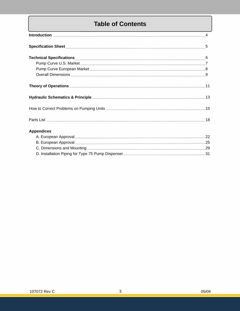
Table of Contents
Introduction 4 Specification Sheet 5
Pump Curve European Market 8 Overall Dimensions 9
Theory of Operations 11 Hydraulic Schematics & Principle 13 How to Correct Problems on Pumping Units 15 Parts List 18 Appendices
A. European Approval 22
Technical Specifications 6
Pump Curve U.S. Market 7
B. European Approval 25 C. Dimensions and Mounting 29 D. Installation Piping for Type 75 Pump Dispenser 31
107072 Rev C 05/09 4
Introduction
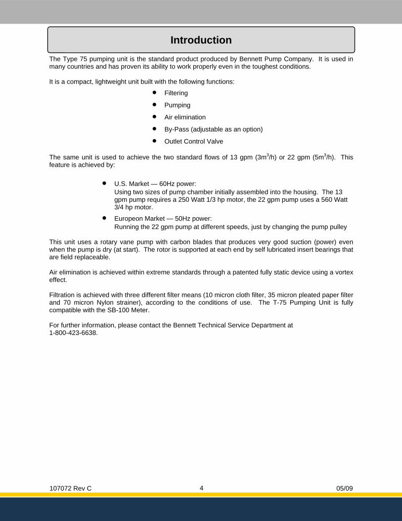
The Type 75 pumping unit is the standard product produced by Bennett Pump Company. It is used in many countries and has proven its ability to work properly even in the toughest conditions. It is a compact, lightweight unit built with the following functions:
• Filtering
• Pumping
• Air elimination
• By-Pass (adjustable as an option)
• Outlet Control Valve The same unit is used to achieve the two standard flows of 13 gpm (3m3/h) or 22 gpm (5m3/h). This feature is achieved by:
• U.S. Market — 60Hz power: Using two sizes of pump chamber initially assembled into the housing. The 13 gpm pump requires a 250 Watt 1/3 hp motor, the 22 gpm pump uses a 560 Watt 3/4 hp motor.
• Europeon Market — 50Hz power: Running the 22 gpm pump at different speeds, just by changing the pump pulley
This unit uses a rotary vane pump with carbon blades that produces very good suction (power) even when the pump is dry (at start). The rotor is supported at each end by self lubricated insert bearings that are field replaceable. Air elimination is achieved within extreme standards through a patented fully static device using a vortex effect. Filtration is achieved with three different filter means (10 micron cloth filter, 35 micron pleated paper filter and 70 micron Nylon strainer), according to the conditions of use. The T-75 Pumping Unit is fully compatible with the SB-100 Meter. For further information, please contact the Bennett Technical Service Department at 1-800-423-6638.
107072 Rev C 05/09 5
Specification Sheet
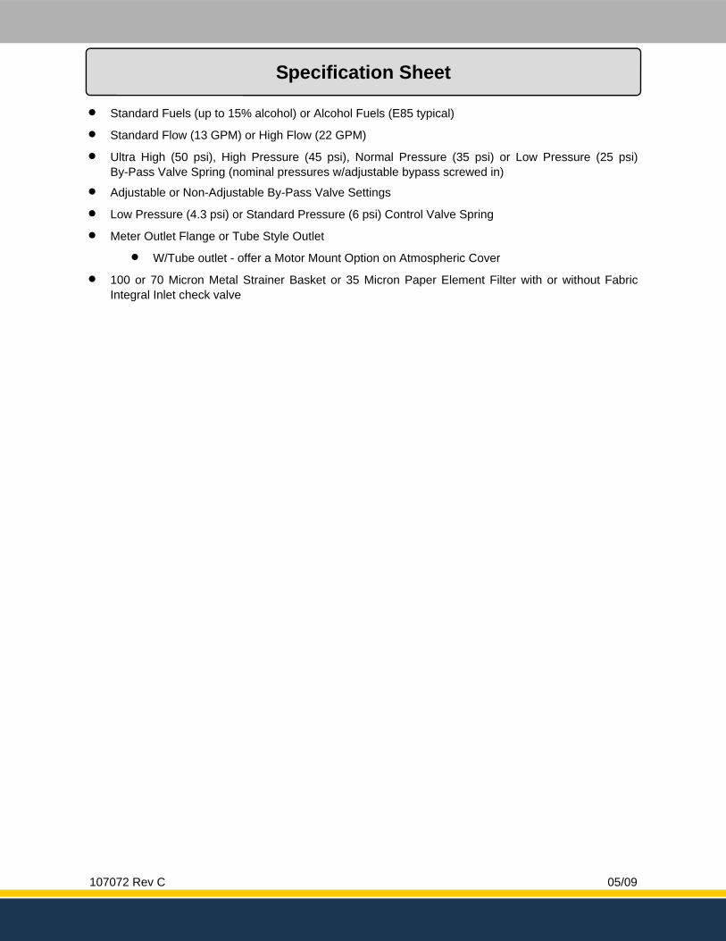
• Standard Fuels (up to 15% alcohol) or Alcohol Fuels (E85 typical)
• Standard Flow (13 GPM) or High Flow (22 GPM)
• Ultra High (50 psi), High Pressure (45 psi), Normal Pressure (35 psi) or Low Pressure (25 psi) By-Pass Valve Spring (nominal pressures w/adjustable bypass screwed in)
• Adjustable or Non-Adjustable By-Pass Valve Settings
• Low Pressure (4.3 psi) or Standard Pressure (6 psi) Control Valve Spring
• Meter Outlet Flange or Tube Style Outlet
• W/Tube outlet - offer a Motor Mount Option on Atmospheric Cover
• 100 or 70 Micron Metal Strainer Basket or 35 Micron Paper Element Filter with or without Fabric Integral Inlet check valve
107072 Rev C 05/09 6
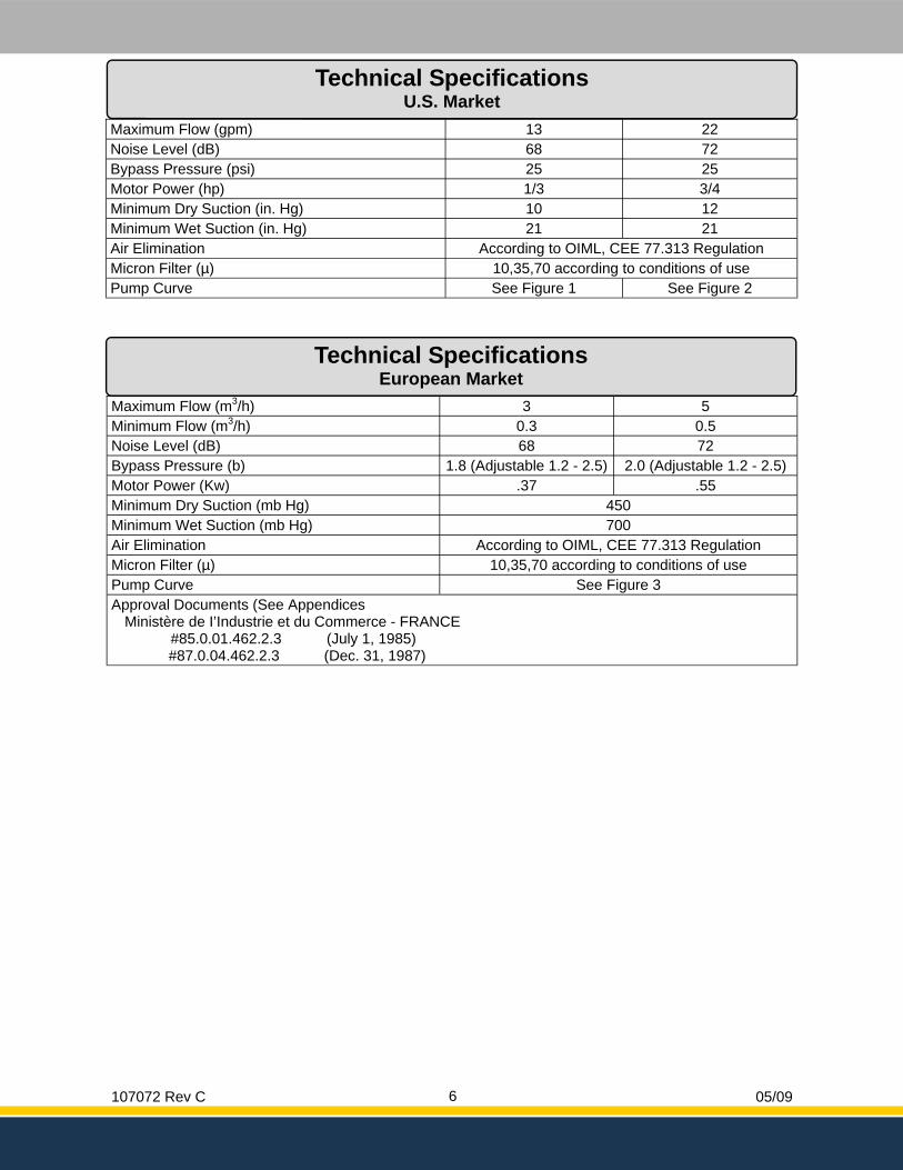
Technical Specifications U.S. Market
Technical Specifications European Market
Maximum Flow (gpm) 13 22 Noise Level (dB) 68 72 Bypass Pressure (psi) 25 25 Motor Power (hp) 1/3 3/4 Minimum Dry Suction (in. Hg) 10 12 Minimum Wet Suction (in. Hg) 21 21 Air Elimination According to OIML, CEE 77.313 Regulation Micron Filter (µ) 10,35,70 according to conditions of use Pump Curve See Figure 1 See Figure 2
Maximum Flow (m3/h) 3 5 Minimum Flow (m3/h) 0.3 0.5 Noise Level (dB) 68 72 Bypass Pressure (b) 1.8 (Adjustable 1.2 - 2.5) 2.0 (Adjustable 1.2 - 2.5) Motor Power (Kw) .37 .55 Minimum Dry Suction (mb Hg) 450 Minimum Wet Suction (mb Hg) 700 Air Elimination According to OIML, CEE 77.313 Regulation Micron Filter (µ) 10,35,70 according to conditions of use Pump Curve Approval Documents (See Appendices
Ministère de I’Industrie et du Commerce - FRANCE #85.0.01.462.2.3 (July 1, 1985)
#87.0.04.462.2.3 (Dec. 31, 1987)
See Figure 3
107072 Rev C 05/09 7
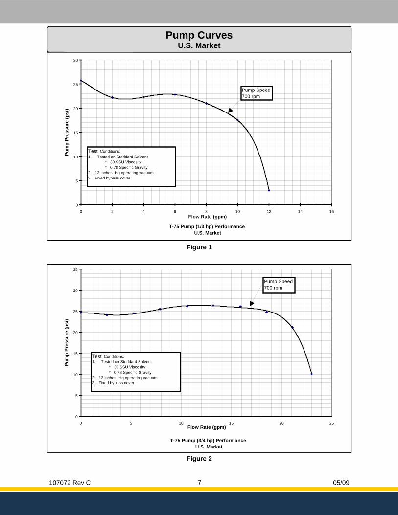
T-75 Pump (3/4 hp) Performance U.S. Market
0
5
10
15
20
25
30
35
0 5 10 15 20 25Flow Rate (gpm)
Pum
p Pr
essu
re (p
si)
Pump Speed700 rpm
Test Conditions:1. Tested on Stoddard Solvent * 30 SSU Viscosity * 0.78 Specific Gravity2. 12 inches Hg operating vacuum3. Fixed bypass cover
Figure 2
T-75 Pump (1/3 hp) Performance U.S. Market
0
5
10
15
20
25
30
0 2 4 6 8 10 12 14 16Flow Rate (gpm)
Pum
p Pr
essu
re (p
si)
Test Conditions:1. Tested on Stoddard Solvent * 30 SSU Viscosity * 0.78 Specific Gravity2. 12 inches Hg operating vacuum3. Fixed bypass cover
Pump Speed700 rpm
Figure 1
Pump Curves U.S. Market
107072 Rev C 05/09 8
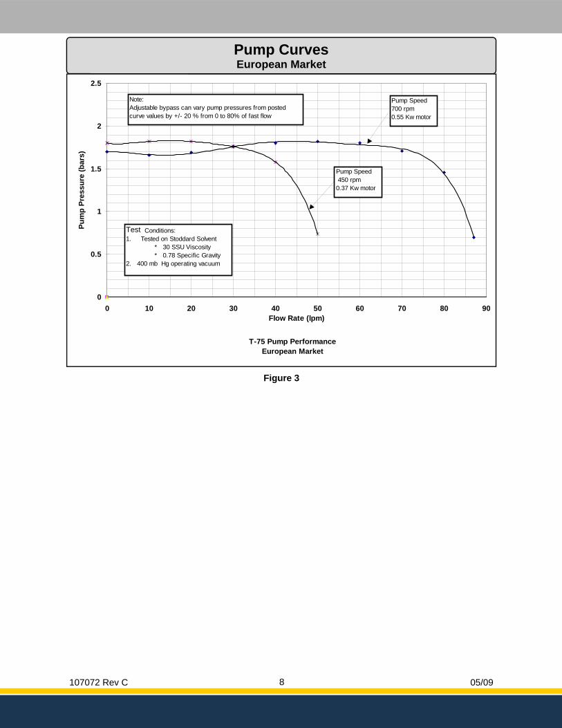
T-75 Pump Performance European Market
0
0.5
1
1.5
2
2.5
0 10 20 30 40 50 60 70 80 90Flow Rate (lpm)
Pum
p Pr
essu
re (b
ars)
Pump Speed700 rpm0.55 Kw motor
Note:Adjustable bypass can vary pump pressures from postedcurve values by +/- 20 % from 0 to 80% of fast flow
Test Conditions:1. Tested on Stoddard Solvent * 30 SSU Viscosity * 0.78 Specific Gravity2. 400 mb Hg operating vacuum
Pump Speed 450 rpm0.37 Kw motor
Page 15
Figure 3
Pump Curves European Market
107072 Rev C 05/09 9
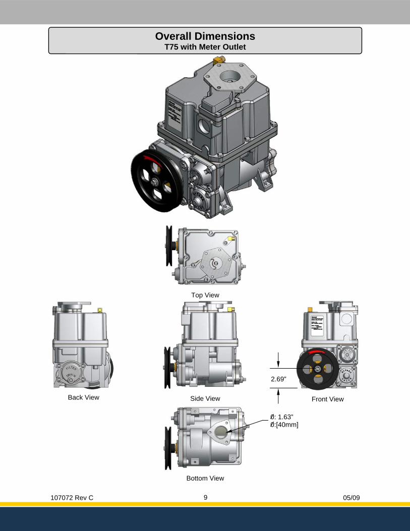
Overall Dimensions T75 with Meter Outlet
Bottom View
Side View
Top View
Front View Back View
2.69”
0: 1.63” 0:[40mm]
107072 Rev C 05/09 10
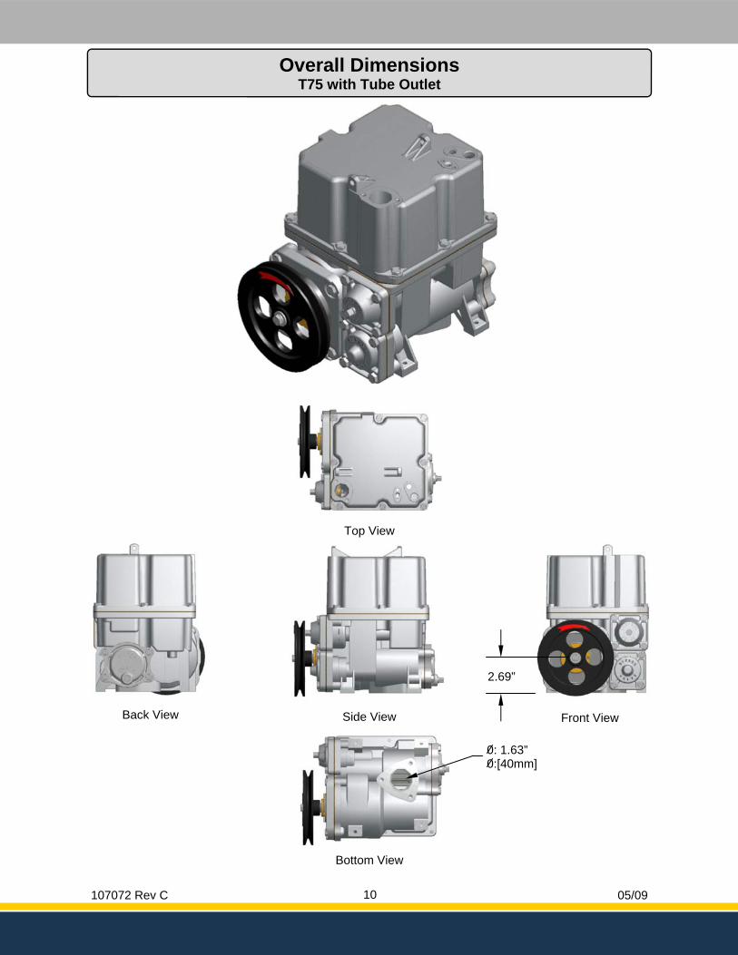
Overall Dimensions T75 with Tube Outlet
Bottom View
Side View
Top View
Front View Back View
2.69”
0: 1.63” 0:[40mm]
107072 Rev C 05/09 11
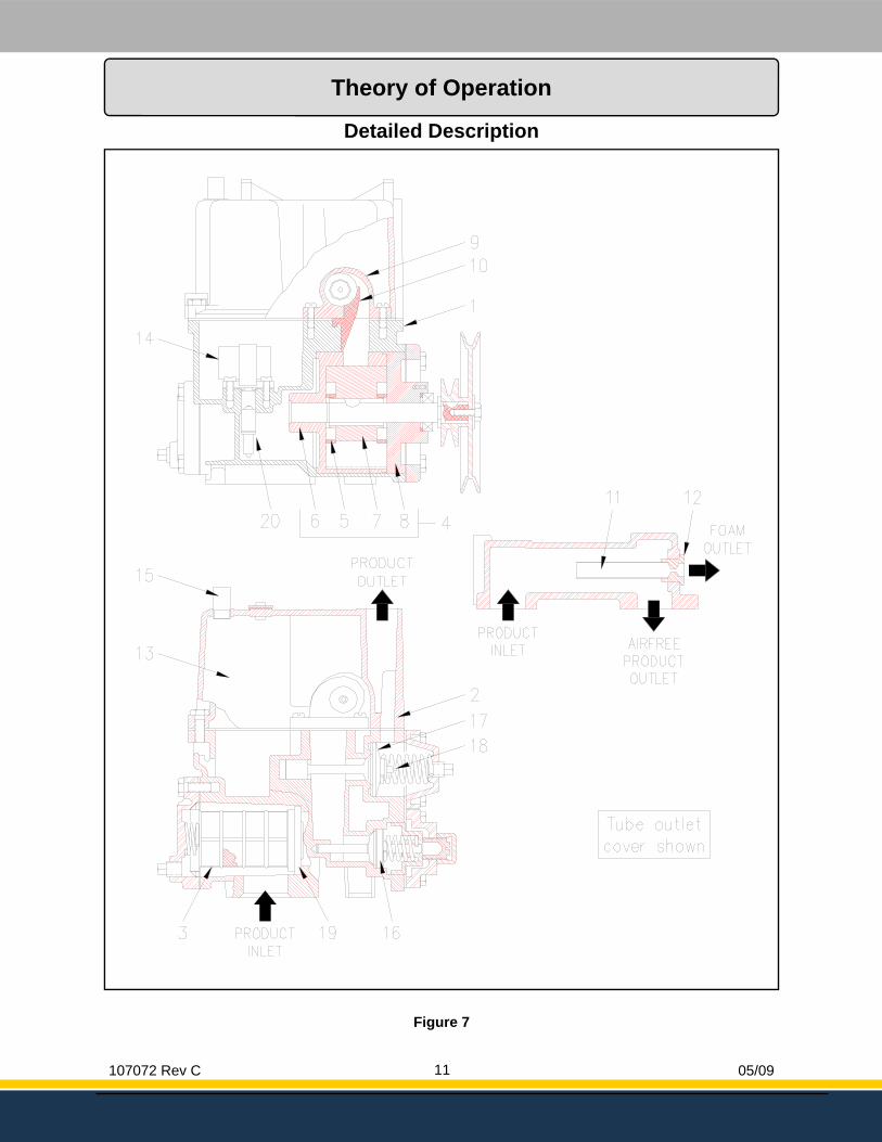
Detailed Description
Figure 7
Theory of Operation
107072 Rev C 05/09 12
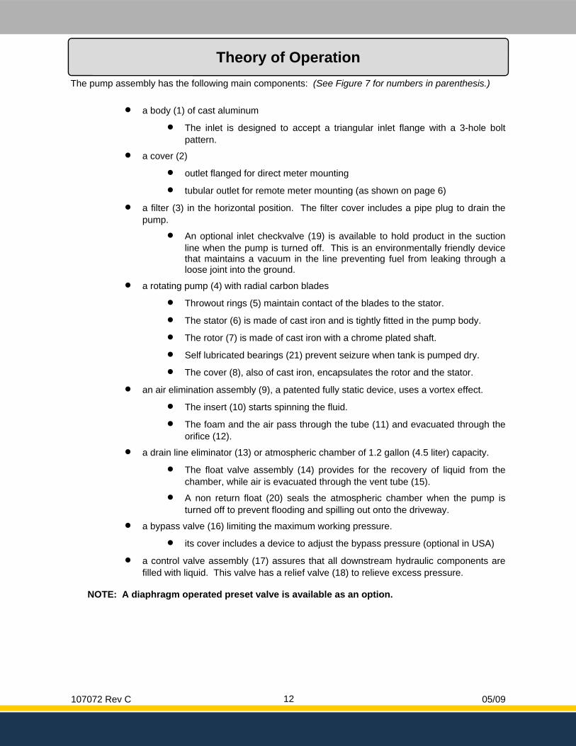
The pump assembly has the following main components: (See Figure 7 for numbers in parenthesis.)
• a body (1) of cast aluminum
• The inlet is designed to accept a triangular inlet flange with a 3-hole bolt pattern.
• a cover (2)
• outlet flanged for direct meter mounting
• tubular outlet for remote meter mounting (as shown on page 6)
• a filter (3) in the horizontal position. The filter cover includes a pipe plug to drain the pump.
• An optional inlet checkvalve (19) is available to hold product in the suction line when the pump is turned off. This is an environmentally friendly device that maintains a vacuum in the line preventing fuel from leaking through a loose joint into the ground.
• a rotating pump (4) with radial carbon blades
• Throwout rings (5) maintain contact of the blades to the stator.
• The stator (6) is made of cast iron and is tightly fitted in the pump body.
• The rotor (7) is made of cast iron with a chrome plated shaft.
• Self lubricated bearings (21) prevent seizure when tank is pumped dry.
• The cover (8), also of cast iron, encapsulates the rotor and the stator.
• an air elimination assembly (9), a patented fully static device, uses a vortex effect.
• The insert (10) starts spinning the fluid.
• The foam and the air pass through the tube (11) and evacuated through the orifice (12).
• a drain line eliminator (13) or atmospheric chamber of 1.2 gallon (4.5 liter) capacity.
• The float valve assembly (14) provides for the recovery of liquid from the chamber, while air is evacuated through the vent tube (15).
• A non return float (20) seals the atmospheric chamber when the pump is turned off to prevent flooding and spilling out onto the driveway.
• a bypass valve (16) limiting the maximum working pressure.
• its cover includes a device to adjust the bypass pressure (optional in USA)
• a control valve assembly (17) assures that all downstream hydraulic components are filled with liquid. This valve has a relief valve (18) to relieve excess pressure.
NOTE: A diaphragm operated preset valve is available as an option.
Theory of Operation
107072 Rev C 05/09 13
Figure 8
Figure 9
Hydraulic Schematics & Principle
107072 Rev C 05/09 14
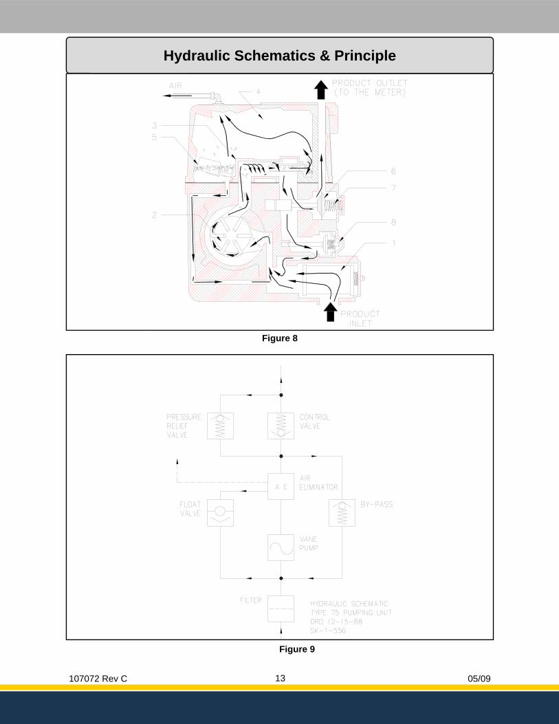
(See Figure 8 for numbers in parenthesis.) The product is drawn from the underground storage tank through the strainer screen of filter (1). The rotary van pumping unit (2) pressurizes the fluid. Product enters the centrifugal air separator assembly (3). Any air present is forced out the air tube along with a small amount of liquid into the atmospheric chamber (4). Product collected in the atmospheric chamber is returned to the pump intake across the non return float when the liquid level in the chamber lifts the float and valve assembly from its seat (5). Any air is then vented to the atmosphere through the vent tube. Air free product leaving the air separator opens the control valve (6) and is pumped to the meter. The control valve includes a built-in relief valve (7) which relieves excess pressure caused by hot weather expansion. Product passes through the meter where it is accurately measured, then through the hose and nozzle into the vehicle being fueled. Whenever the nozzle is not fully opened, some liquid is relieved into the pump intake through the bypass valve (8).
Hydraulic Schematics & Principle
107072 Rev C 05/09 15
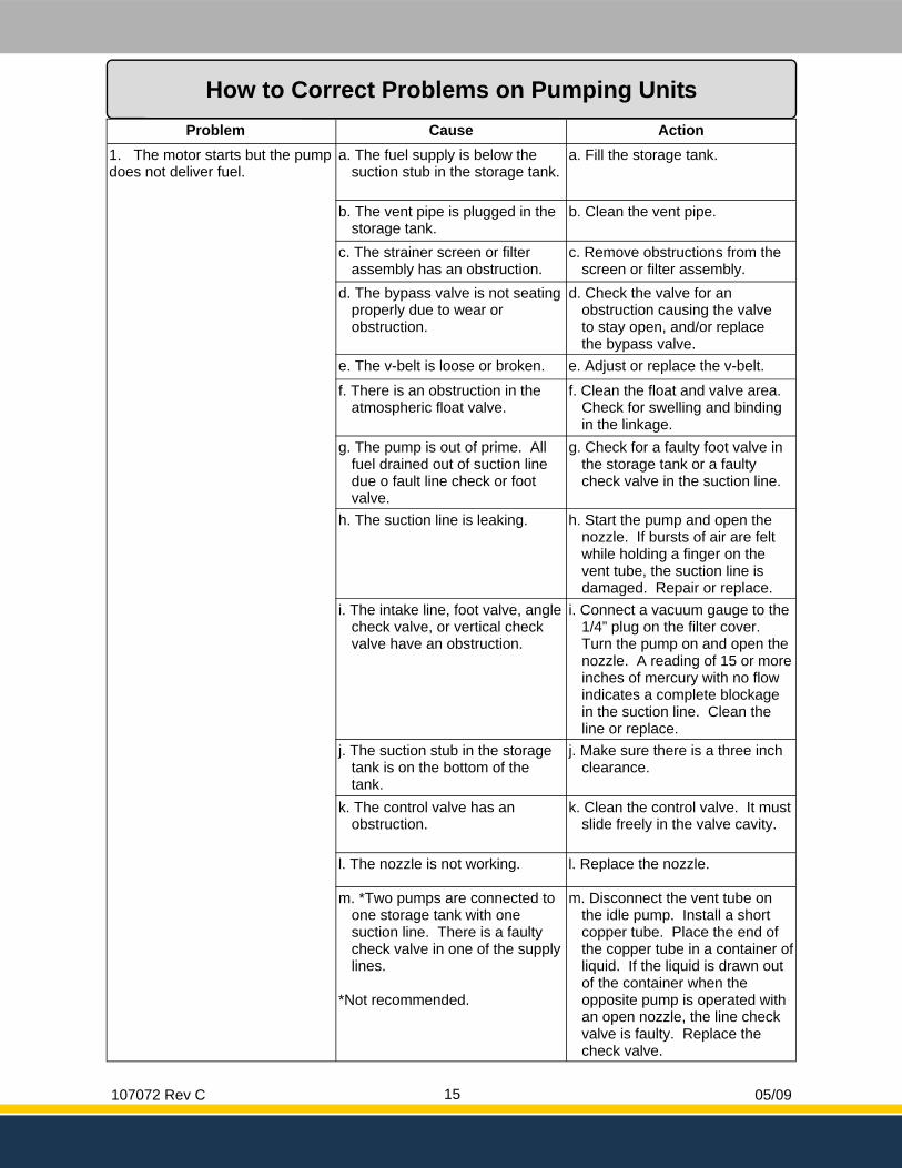
Problem Cause Action 1. The motor starts but the pump does not deliver fuel.
a. The fuel supply is below the suction stub in the storage tank.
a. Fill the storage tank.
b. The vent pipe is plugged in the storage tank.
b. Clean the vent pipe.
c. The strainer screen or filter assembly has an obstruction.
c. Remove obstructions from the screen or filter assembly.
d. The bypass valve is not seating properly due to wear or obstruction.
d. Check the valve for an obstruction causing the valve to stay open, and/or replace the bypass valve.
e. The v-belt is loose or broken. e. Adjust or replace the v-belt.
f. There is an obstruction in the atmospheric float valve.
f. Clean the float and valve area. Check for swelling and binding in the linkage.
g. The pump is out of prime. All fuel drained out of suction line due o fault line check or foot valve.
g. Check for a faulty foot valve in the storage tank or a faulty check valve in the suction line.
h. The suction line is leaking. h. Start the pump and open the nozzle. If bursts of air are felt while holding a finger on the vent tube, the suction line is damaged. Repair or replace.
i. The intake line, foot valve, angle check valve, or vertical check valve have an obstruction.
i. Connect a vacuum gauge to the 1/4” plug on the filter cover. Turn the pump on and open the nozzle. A reading of 15 or more inches of mercury with no flow indicates a complete blockage in the suction line. Clean the line or replace.
j. The suction stub in the storage tank is on the bottom of the tank.
j. Make sure there is a three inch clearance.
k. The control valve has an obstruction.
k. Clean the control valve. It must slide freely in the valve cavity.
l. The nozzle is not working. l. Replace the nozzle.
m. *Two pumps are connected to one storage tank with one suction line. There is a faulty check valve in one of the supply lines.
*Not recommended.
m. Disconnect the vent tube on the idle pump. Install a short copper tube. Place the end of the copper tube in a container of liquid. If the liquid is drawn out of the container when the opposite pump is operated with an open nozzle, the line check valve is faulty. Replace the check valve.
How to Correct Problems on Pumping Units
107072 Rev C 05/09 16
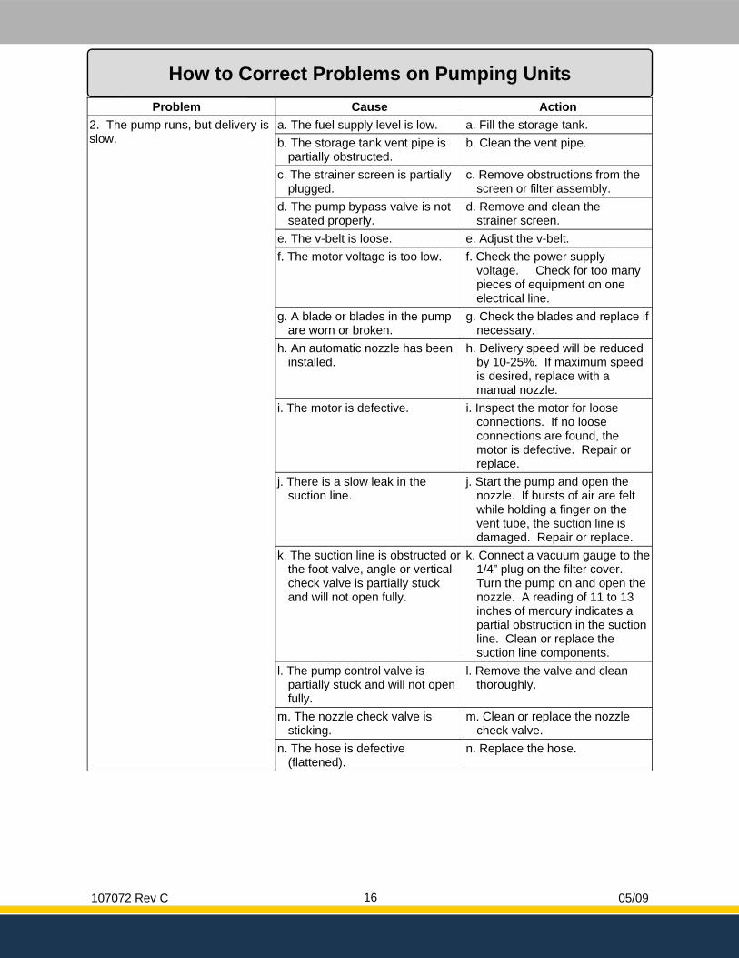
Problem Cause Action 2. The pump runs, but delivery is slow.
a. The fuel supply level is low. a. Fill the storage tank. b. The storage tank vent pipe is
partially obstructed. b. Clean the vent pipe.
c. The strainer screen is partially plugged.
c. Remove obstructions from the screen or filter assembly.
d. The pump bypass valve is not seated properly.
d. Remove and clean the strainer screen.
e. The v-belt is loose. e. Adjust the v-belt. f. The motor voltage is too low. f. Check the power supply
voltage. Check for too many pieces of equipment on one electrical line.
g. A blade or blades in the pump are worn or broken.
g. Check the blades and replace if necessary.
h. An automatic nozzle has been installed.
h. Delivery speed will be reduced by 10-25%. If maximum speed is desired, replace with a manual nozzle.
i. The motor is defective. i. Inspect the motor for loose connections. If no loose connections are found, the motor is defective. Repair or replace.
j. There is a slow leak in the suction line.
j. Start the pump and open the nozzle. If bursts of air are felt while holding a finger on the vent tube, the suction line is damaged. Repair or replace.
k. The suction line is obstructed or the foot valve, angle or vertical check valve is partially stuck and will not open fully.
k. Connect a vacuum gauge to the 1/4” plug on the filter cover. Turn the pump on and open the nozzle. A reading of 11 to 13 inches of mercury indicates a partial obstruction in the suction line. Clean or replace the suction line components.
l. The pump control valve is partially stuck and will not open fully.
l. Remove the valve and clean thoroughly.
m. The nozzle check valve is sticking.
m. Clean or replace the nozzle check valve.
n. The hose is defective (flattened).
n. Replace the hose.
How to Correct Problems on Pumping Units
107072 Rev C 05/09 17
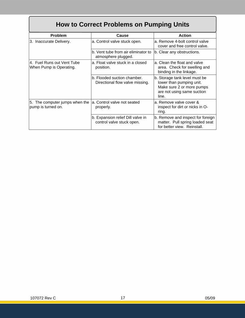
Problem Cause Action 3. Inaccurate Delivery. a. Control valve stuck open. a. Remove 4-bolt control valve
cover and free control valve. b. Vent tube from air eliminator to
atmosphere plugged. b. Clear any obstructions.
4. Fuel Runs out Vent Tube When Pump is Operating.
a. Float valve stuck in a closed position.
a. Clean the float and valve area. Check for swelling and binding in the linkage.
b. Flooded suction chamber. Directional flow valve missing.
b. Storage tank level must be lower than pumping unit. Make sure 2 or more pumps are not using same suction line.
5. The computer jumps when the pump is turned on.
a. Control valve not seated properly.
a. Remove valve cover & inspect for dirt or nicks in O-ring.
b. Expansion relief Dill valve in control valve stuck open.
b. Remove and inspect for foreign matter. Pull spring loaded seat for better view. Reinstall.
How to Correct Problems on Pumping Units
107072 Rev C 05/09 18
Parts List
107072 Rev C 05/09 19
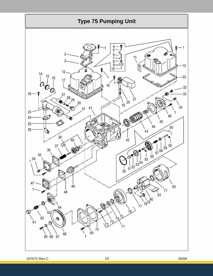
Type 75 Pumping Unit
107072 Rev C 05/09 20
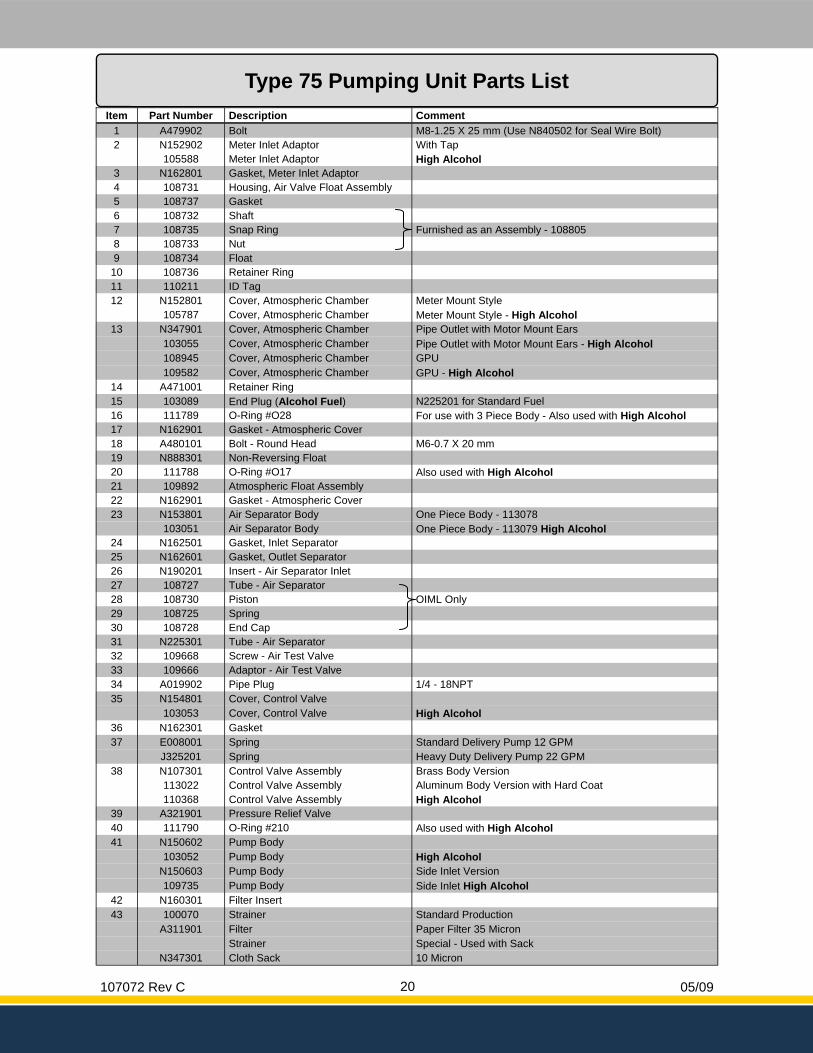
Type 75 Pumping Unit Parts List Item Part Number Description Comment
1 A479902 Bolt M8-1.25 X 25 mm (Use N840502 for Seal Wire Bolt) 2 N152902 Meter Inlet Adaptor With Tap
105588 Meter Inlet Adaptor High Alcohol 3 N162801 Gasket, Meter Inlet Adaptor 4 108731 Housing, Air Valve Float Assembly 5 108737 Gasket 6 108732 Shaft 7 108735 Snap Ring Furnished as an Assembly - 108805 8 108733 Nut 9 108734 Float
10 108736 Retainer Ring 11 110211 ID Tag 12 N152801 Cover, Atmospheric Chamber Meter Mount Style
105787 Cover, Atmospheric Chamber Meter Mount Style - High Alcohol 13 N347901 Cover, Atmospheric Chamber Pipe Outlet with Motor Mount Ears 103055 Cover, Atmospheric Chamber Pipe Outlet with Motor Mount Ears - High Alcohol 108945 Cover, Atmospheric Chamber GPU 109582 Cover, Atmospheric Chamber GPU - High Alcohol
14 A471001 Retainer Ring 15 103089 End Plug (Alcohol Fuel) N225201 for Standard Fuel 16 111789 O-Ring #O28 For use with 3 Piece Body - Also used with High Alcohol 17 N162901 Gasket - Atmospheric Cover 18 A480101 Bolt - Round Head M6-0.7 X 20 mm 19 N888301 Non-Reversing Float 20 111788 O-Ring #O17 Also used with High Alcohol 21 109892 Atmospheric Float Assembly 22 N162901 Gasket - Atmospheric Cover 23 N153801 Air Separator Body One Piece Body - 113078
103051 Air Separator Body One Piece Body - 113079 High Alcohol 24 N162501 Gasket, Inlet Separator 25 N162601 Gasket, Outlet Separator 26 N190201 Insert - Air Separator Inlet 27 108727 Tube - Air Separator 28 108730 Piston OIML Only 29 108725 Spring 30 108728 End Cap 31 N225301 Tube - Air Separator 32 109668 Screw - Air Test Valve 33 109666 Adaptor - Air Test Valve 34 A019902 Pipe Plug 1/4 - 18NPT 35 N154801 Cover, Control Valve 103053 Cover, Control Valve High Alcohol
36 N162301 Gasket 37 E008001 Spring Standard Delivery Pump 12 GPM J325201 Spring Heavy Duty Delivery Pump 22 GPM
38 N107301 Control Valve Assembly Brass Body Version 113022 Control Valve Assembly Aluminum Body Version with Hard Coat
39 A321901 Pressure Relief Valve 40 111790 O-Ring #210 Also used with High Alcohol 41 N150602 Pump Body 103052 Pump Body High Alcohol N150603 Pump Body Side Inlet Version 109735 Pump Body Side Inlet High Alcohol
42 N160301 Filter Insert 43 100070 Strainer Standard Production A311901 Filter Paper Filter 35 Micron Strainer Special - Used with Sack N347301 Cloth Sack 10 Micron
110368 Control Valve Assembly High Alcohol
107072 Rev C 05/09 21
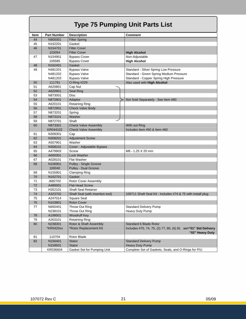
Type 75 Pumping Unit Parts List Item Part Number Description Comment 44 N905001 Filter Spring 45 N162201 Gasket 46 N154701 Filter Cover 103054 Filter Cover High Alcohol
47 N154901 Bypass Cover Non-Adjustable 105585 Bypass Cover High Alcohol
48 N162401 Gasket 49 N481201 Bypass Valve Standard - Silver Spring Low Pressure
N481202 Bypass Valve Standard - Green Spring Medium Pressure N481203 Bypass Valve Standard - Copper Spring High Pressure
50 111791 O-Ring #229 Also used with High Alcohol 51 A620801 Cap Nut 52 A620901 Seal Ring 53 N873001 Disc 54 N872801 Adaptor Not Sold Separately - See Item #60 55 A620101 Retaining Ring 56 N872901 Check Valve Body 57 N873201 Spring 58 N873101 Washer 59 N872701 Shaft 60 N873301 Check Valve Assembly With out Ring
61 N308301 Cap 62 N308201 Adjustment Screw 63 A507901 Washer 64 N308101 Cover - Adjustable Bypass 65 A479903 Screw M8 - 1.25 X 20 mm 66 A000301 Lock Washer 67 A028101 Flat Washer 68 N106901 Pulley - Single Groove 100040 Pulley - Dual Groove
69 N155901 Clamping Ring 70 N162701 Gasket 71 J682702 Rotor Cover Assembly 72 A480001 Flat Head Screw 73 H352101 Shaft Seal Retainer 74 A323702 Shaft Seal (with insertion tool) 109711 Shaft Seal Kit - Includes #74 & 75 with install plug 75 A247014 Square Seal 76 N103801 Rotor Cover 77 N650401 Throw Out Ring Standard Delivery Pump
N238101 Throw Out Ring Heavy Duty Pump 78 A199501 Woodruff Key 79 A263101 Retaining Ring 80 N238301 Rotor & Shaft Assembly Standard 6 Blade Rotor *KR0420xx *Rotor Replacement Kit Includes #70, 74, 75, (2) 77, 80, (6) 81 xx=“01” Std Delivery
81 110704 Rotor Blade 82 N156401 Stator Standard Delivery Pump N159501 Stator Heavy Duty Pump
KR036604 Gasket Set for Pumping Unit Complete Set of Gaskets, Seals, and O-Rings for P/U
KR044102 Check Valve Assembly Includes Item #50 & Item #60
“02” Heavy Duty
107072 Rev C 05/09 22
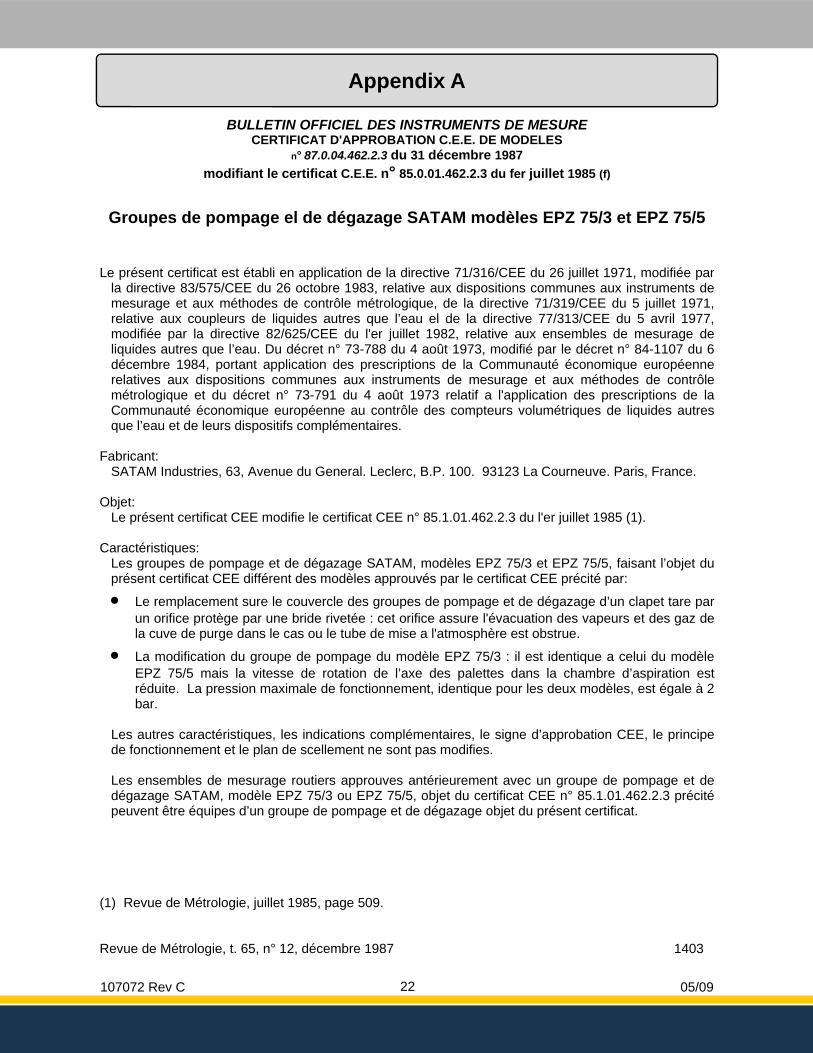
Appendix A
BULLETIN OFFICIEL DES INSTRUMENTS DE MESURE CERTIFICAT D'APPROBATION C.E.E. DE MODELES
n° 87.0.04.462.2.3 du 31 décembre 1987 modifiant le certificat C.E.E. n° 85.0.01.462.2.3 du fer juillet 1985 (f)
Groupes de pompage el de dégazage SATAM modèles EPZ 75/3 et EPZ 75/5
Le présent certificat est établi en application de la directive 71/316/CEE du 26 juillet 1971, modifiée par la directive 83/575/CEE du 26 octobre 1983, relative aux dispositions communes aux instruments de mesurage et aux méthodes de contrôle métrologique, de la directive 71/319/CEE du 5 juillet 1971, relative aux coupleurs de liquides autres que l’eau el de la directive 77/313/CEE du 5 avril 1977, modifiée par la directive 82/625/CEE du l'er juillet 1982, relative aux ensembles de mesurage de liquides autres que l’eau. Du décret n° 73-788 du 4 août 1973, modifié par le décret n° 84-1107 du 6 décembre 1984, portant application des prescriptions de la Communauté économique européenne relatives aux dispositions communes aux instruments de mesurage et aux méthodes de contrôle métrologique et du décret n° 73-791 du 4 août 1973 relatif a l'application des prescriptions de la Communauté économique européenne au contrôle des compteurs volumétriques de liquides autres que l’eau et de leurs dispositifs complémentaires.
Fabricant:
SATAM Industries, 63, Avenue du General. Leclerc, B.P. 100. 93123 La Courneuve. Paris, France. Objet:
Le présent certificat CEE modifie le certificat CEE n° 85.1.01.462.2.3 du l'er juillet 1985 (1).
Caractéristiques: Les groupes de pompage et de dégazage SATAM, modèles EPZ 75/3 et EPZ 75/5, faisant l’objet du présent certificat CEE différent des modèles approuvés par le certificat CEE précité par:
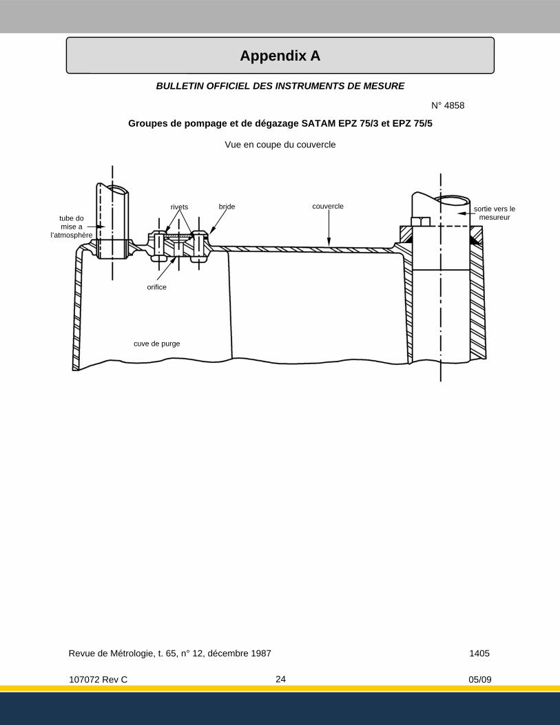
• Le remplacement sure le couvercle des groupes de pompage et de dégazage d’un clapet tare par un orifice protège par une bride rivetée : cet orifice assure l'évacuation des vapeurs et des gaz de la cuve de purge dans le cas ou le tube de mise a l'atmosphère est obstrue.
• La modification du groupe de pompage du modèle EPZ 75/3 : il est identique a celui du modèle EPZ 75/5 mais la vitesse de rotation de l’axe des palettes dans la chambre d’aspiration est réduite. La pression maximale de fonctionnement, identique pour les deux modèles, est égale à 2 bar.
Les autres caractéristiques, les indications complémentaires, le signe d’approbation CEE, le principe de fonctionnement et le plan de scellement ne sont pas modifies. Les ensembles de mesurage routiers approuves antérieurement avec un groupe de pompage et de dégazage SATAM, modèle EPZ 75/3 ou EPZ 75/5, objet du certificat CEE n° 85.1.01.462.2.3 précité peuvent être équipes d’un groupe de pompage et de dégazage objet du présent certificat.
(1) Revue de Métrologie, juillet 1985, page 509. Revue de Métrologie, t. 65, n° 12, décembre 1987 1403
107072 Rev C 05/09 23
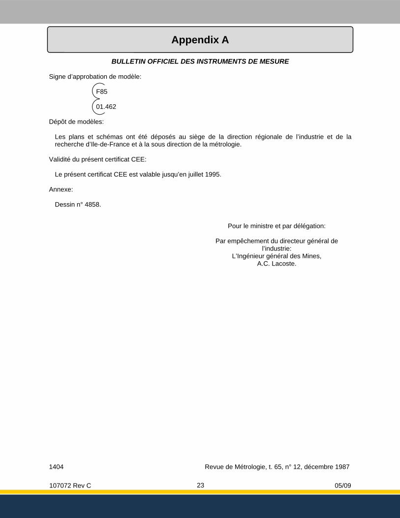
Appendix A
BULLETIN OFFICIEL DES INSTRUMENTS DE MESURE Signe d’approbation de modèle:
F85 01.462
Dépôt de modèles:
Les plans et schémas ont été déposés au siège de la direction régionale de l’industrie et de la recherche d’Ile-de-France et à la sous direction de la métrologie.
Validité du présent certificat CEE:
Le présent certificat CEE est valable jusqu’en juillet 1995. Annexe:
Dessin n° 4858.
Pour le ministre et par délégation:
Par empêchement du directeur général de l’industrie:
L’Ingénieur général des Mines, A.C. Lacoste.
1404 Revue de Métrologie, t. 65, n° 12, décembre 1987
107072 Rev C 05/09 24
Appendix A
BULLETIN OFFICIEL DES INSTRUMENTS DE MESURE
Revue de Métrologie, t. 65, n° 12, décembre 1987 1405
N° 4858
Groupes de pompage et de dégazage SATAM EPZ 75/3 et EPZ 75/5
Vue en coupe du couvercle
tube do mise a
l’atmosphère
rivets bride couvercle sortie vers le mesureur
orifice
cuve de purge
107072 Rev C 05/09 25
Appendix B
BULLETIN DES INSTRUMENTS DE MESURE JUILLET 1985
CERTIFICAT D'APPROBATION C.E.E. DE MODELES n° 85.0.01.462.2.3 du fer juillet 1985
Groupes de pompage el de dégazage SATAM modèles EPZ 75/3 et EPZ 75/5
(Précision commerciale)
Le présent certificat est établi en application de la directive 71/316/CEE du 26 juillet 1971, relative aux dispositions communes aux instruments de mesurage et aux méthodes de contrôle métrologique, de la directive 71/319/CEE du 26 juillet 1971, relative aux coupleurs de liquides autres que l’eau Du décret n° 73-788 du 4 août 1973 portant application des prescriptions de la CEE relatives aux dispositions communes aux instruments de mesurage et aux méthodes de contrôle métrologique du décret n° 73-791 du 4 août 1973 relatif à l'application des prescriptions de la CEE au contrôle des compteurs volumétriques de liquides autres que l’eau et de leurs dispositifs complémentaires et de l’arrêté du8 novembre 1973 relatif aux modales d’application de certaines dispositions du décret n° 73-788 du 4 août 1973, de l’arrêté du 20 novembre 1973 portant application du décret n° 73-791 di 4 aout 1973 et de l’arrêté du 19 juin 1978 relatif à l'application des prescriptions de la CEE au contrôle des ensembles de mesurage à computeur columetrique destines à determines le volume des liquides outres que l’eau.
Fabricant:
SATAM Industries, 63, Avenue du General. Leclerc, B.P. 100. 93123 La Courneuve. Paris, France. Caractéristiques:
Les groupes de pompage et de dégazage SATAM, modèles EPZ 75/3 et EPZ 75/5, sont destines au mesurage de l’essence, do supercarburant et du gazole. Ils sont composes des éléments suivants:
• Un filtre avec couvercle amovible.
• Une pompe rotative a six palettes radiales.
• Un séparateur de gaz statique a effet VORTEX.
• Une cuve de purge.
• Un clapet de bipasse.
• Un clapet anti-retour.
• Un orifice de refoulement vers le mesureur. Ces deux modèles différent par la cylindrée do la chambre d’aspiration de la pompe. En outre, le modèle EPZ 75/7 comporte une bague de guidage des palettes.
107072 Rev C 05/09 26
Appendix B
BULLETIN DES INSTRUMENTS DE MESURE JUILLET 1985
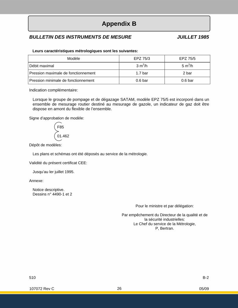
Leurs caractéristiques métrologiques sont les suivantes:
Modèle EPZ 75/3 EPZ 75/5
Débit maximal 3 m3/h 5 m3/h
Pression maximale de fonctionnement 1.7 bar 2 bar
Pression minimale de fonctionnement 0.6 bar 0.6 bar
Indication complémentaire:
Lorsque le groupe de pompage et de dégazage SATAM, modèle EPZ 75/5 est incorporé dans un ensemble de mesurage routier destiné au mesurage de gazole, un indicateur de gaz doit être dispose en amont du flexible de l’ensemble.
Signe d’approbation de modèle:
F85 01.462
Dépôt de modèles:
Les plans et schémas ont été déposés au service de la métrologie. Validité du présent certificat CEE:
Jusqu’au ler juillet 1995. Annexe:
Notice descriptive. Dessins n° 4490-1 et 2
Pour le ministre et par délégation:
Par empêchement du Directeur de la qualité et de la sécurité industrielles:
Le Chef du service de la Métrologie, P, Bertran.
510 B-2
107072 Rev C 05/09 27
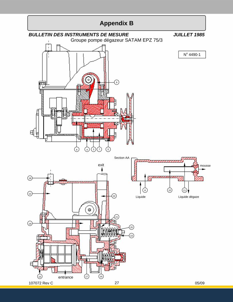
No 4490-1
12
19
4 3 5 6 7
9
10 11 8
Liquide dégaze Liquide
mousse
Section AA
18
22
21
20
16 15 17
23
entrance
exit
BULLETIN DES INSTRUMENTS DE MESURE JUILLET 1985 Groupe pompe dégazeur SATAM EPZ 75/3
Appendix B

107072 Rev C 05/09 28
No 4490-1
12
19
4 3 5 6 7
9
10 11 8
Liquide dégaze Liquide
mousse
Section AA
18
22
21
20
16 15 17
23
entrance
exit
No 4490-2
12
19
4 3 5 6 7
9
10 11 8
Liquide dégaze Liquide
mousse
Section AA
18
22
21
20
16 15 17
23
entrance
exit
24
BULLETIN DES INSTRUMENTS DE MESURE JUILLET 1985 Groupe pompe dégazeur SATAM EPZ 75/5
Appendix B
107072 Rev C 05/09 29
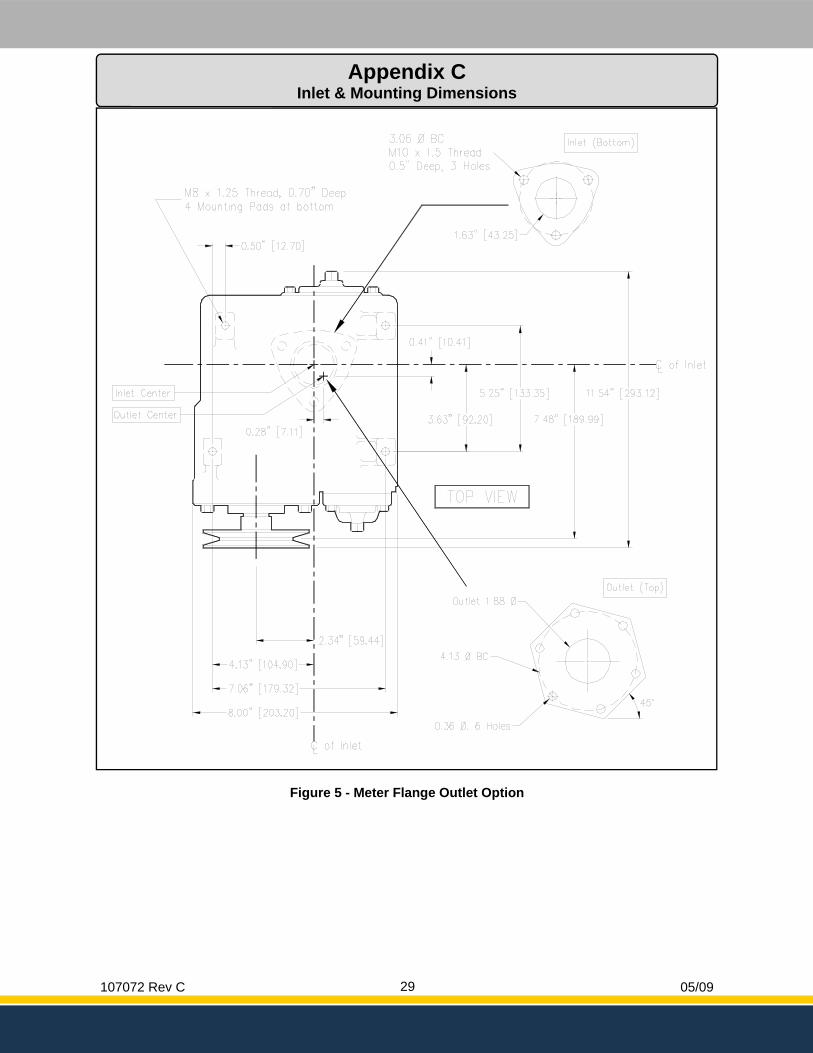
Figure 5 - Meter Flange Outlet Option
Appendix C Inlet & Mounting Dimensions
107072 Rev C 05/09 30
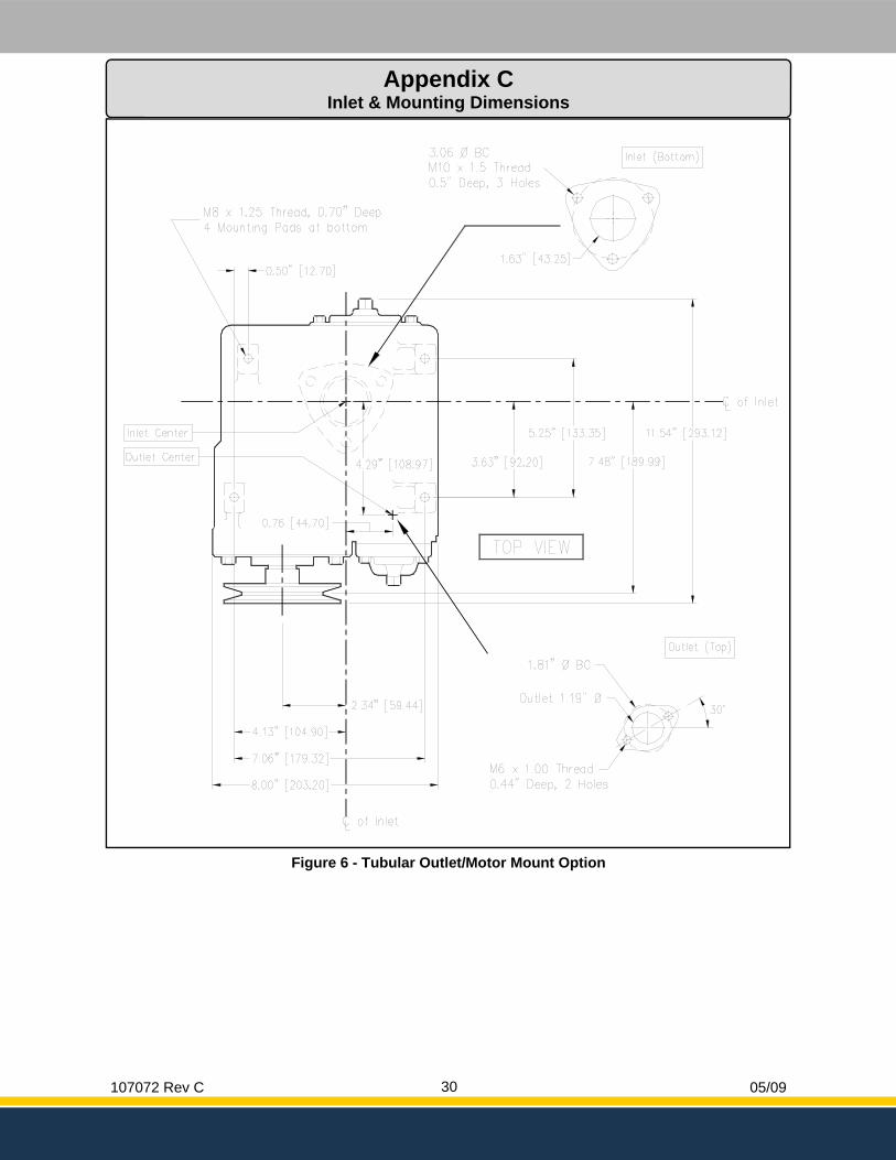
Figure 6 - Tubular Outlet/Motor Mount Option
Appendix C Inlet & Mounting Dimensions
107072 Rev C 05/09 31
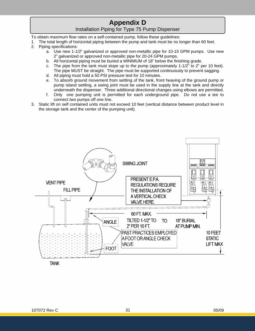
To obtain maximum flow rates on a self-contained pump, follow these guidelines: 1. The total length of horizontal piping between the pump and tank must be no longer than 60 feet. 2. Piping specifications:
a. Use new 1-1/2” galvanized or approved non-metallic pipe for 10-15 GPM pumps. Use new 2” galvanized or approved non-metallic pipe for 20-24 GPM pumps.
b. All horizontal piping must be buried a MINIMUM of 18” below the finishing grade. c. The pipe from the tank must slope up to the pump (approximately 1-1/2” to 2” per 10 feet).
The pipe MUST be straight. The pipe must be supported continuously to prevent sagging. d. All piping must hold a 50 PSI pressure test for 10 minutes. e. To absorb ground movement from settling of the tank, front heaving of the ground pump or
pump island settling, a swing joint must be used in the supply line at the tank and directly underneath the dispenser. Three additional directional changes using elbows are permitted.
f. Only one pumping unit is permitted for each underground pipe. Do not use a tee to connect two pumps off one line.
3. Static lift on self contained units must not exceed 10 feet (vertical distance between product level in the storage tank and the center of the pumping unit).
Appendix D Installation Piping for Type 75 Pump Dispenser
107072 Rev C 05/09 32
Bennett 1218 E. Pontaluna Road Spring Lake, MI 49456 USA 800-235-7618 Outside USA 231-798-1310 [email protected] www.bennettpump.com