Embed Size (px)
Citation preview

1
Benefits of Hybrid-Electric Propulsion to Achieve 4x Increase in Cruise Efficiency for a VTOL Aircraft
William J. Fredericks1, Mark D. Moore2 and Ronald C. Busan3 NASA Langley Research Center, Hampton, VA, 23681
Electric propulsion enables radical new vehicle concepts, particularly for Vertical Takeoff and Landing (VTOL) aircraft because of their significant mismatch between takeoff and cruise power conditions. However, electric propulsion does not merely provide the ability to normalize the power required across the phases of flight, in the way that automobiles also use hybrid electric technologies. The ability to distribute the thrust across the airframe, without mechanical complexity and with a scale-free propulsion system, is a new degree of freedom for aircraft designers. Electric propulsion is scale-free in terms of being able to achieve highly similar levels of motor power to weight and efficiency across a dramatic scaling range. Applying these combined principles of electric propulsion across a VTOL aircraft permits an improvement in aerodynamic efficiency that is approximately four times the state of the art of conventional helicopter configurations. Helicopters typically achieve a lift to drag ratio (L/D) of between 4 and 5, while the VTOL aircraft designed and developed in this research were designed to achieve an L/D of approximately 20. Fundamentally, the ability to eliminate the problem of advancing and retreating rotor blades is shown, without resorting to unacceptable prior solutions such as tail-sitters. This combination of concept and technology also enables a four times increase in range and endurance while maintaining the full VTOL and hover capability provided by a helicopter. Also important is the ability to achieve low disc-loading for low ground impingement velocities, low noise and hover power minimization (thus reducing energy consumption in VTOL phases). This combination of low noise and electric propulsion (i.e. zero emissions) will produce a much more community-friendly class of vehicles. This research provides a review of the concept brainstorming, configuration aerodynamic and mission analysis, as well as subscale prototype construction and flight testing that verifies transition flight control. A final down-selected vehicle is also presented.
Nomenclature BSFC = brake specific fuel consumption CFD = computational fluid dynamics CG = center of gravity FAA = Federal Aviation Administration L/D = lift to drag ratio MTOW = max takeoff weight NASA = National Aeronautics and Space Administration RC = radio control RPM = revolutions per minute TRL = technology readiness level TSFC = thrust specific fuel consumption V = free stream velocity VSP = Vehicle Sketch Pad, a conceptual design geometry tool. VTOL = vertical takeoff and landing 1 Aerospace Engineer, Aeronautics Systems Analysis Branch, 1 North Dryden St. Mail Stop 442, Young Professional. 2 Project Lead, Aeronautics Systems Analysis Branch, 1 North Dryden St. Mail Stop 442, Senior Member. 3 Aerospace Engineer, Flight Dynamics Branch, 8 Langley Blvd. Mail Stop 308, Senior Member.
https://ntrs.nasa.gov/search.jsp?R=20140001088 2018-06-19T02:41:23+00:00Z

2
ηProp = propeller propulsive efficiency
I. Introduction his study was undertaken to explore the possibility of combining two diametrically opposed requirements, specifically, high efficiency cruise with vertical takeoff and landing. With today’s technology levels, a rotorcraft
cannot achieve a 24-hr flight. As a point of reference, the Boeing A160 program has a goal of 24-hr endurance. The Boeing A160 utilizes a two-speed transmission to keep the rotor at its optimal revolutions per minute (RPM) as the forward speed, altitude, and weight of the vehicle change. Also, the fuel fraction must be very large, leading to a large vehicle to attempt to meet such a long endurance requirement. As of Aug 2012, the A160 has demonstrated an endurance of 18.7 hr1. This study was initiated to consider advanced vehicle concepts that may be capable of meeting these requirements by transitioning to wing born flight in order to reduce the power required in cruise. The study considered both near-term and higher risk advanced concepts. During the second phase of this study, 35% and 50% scale prototypes were fabricated to analyze and validate the ability of the advanced vehicle concepts to transition from hovering flight to wing borne flight and back again. Currently ongoing in the third phase of this study is a different vehicle concept using the lessons learned from phase two with more substantial resources to design to a greater degree of confidence.
II. Study Assumptions For simplification of this study, assumptions were made regarding
the empty weight of the aircraft. Performing a structural analysis to determine the empty weight of these proposed vehicles was outside the scope of this study. The V-Bat was used as a baseline; it has an airframe weight fraction of 30 percent; that is structural weight relative to the Maximum TakeOff Weight (MTOW). As seen in Figure 1, the V-Bat has no articulations associated with its airframe. The concepts for this study, which are discussed later, were assumed to have a 40 percent airframe weight fraction, due to their increased structural complexity. The wing aspect ratio was limited to 15 because the structural mass fraction for vehicles in this class is relatively insensitive to aspect ratio when the aspect ratio is less than 15. With a wing aspect ratio greater than 15, the structural mass fraction becomes a more significant contributor to structural and airframe weight.
Two propulsion systems were considered in the study. First was the Cosworth AG engine. Second is a developmental engine made by GS Engineering6 (GSE). In both cases, the engine turns an alternator. Both are a true compression ignition (no spark assist) diesel engines. The Cosworth is a 12 hp engine3 that weighs 20.5 lbs including a 750w alternator. The GSE is an 8 hp engine5 that weighs 5 lbs. The most remarkable characteristics of these engines are they have impressive specific fuel consumptions. They have BSFCs of 0.45 to 0.5 lbs/hp/hr considering the size of the engine, as internal combustion engines suffer from scaling losses as the volume decreases with the cube (mass flow and power) and surface area scales with the square (friction and internal losses).
This study considered the use of hybrid electric propulsion systems to enable distributed propulsion configurations. The electric motor/generators were assumed to have a power-to-weight ratio of 0.5 lb/hp and a conversion efficiency of 95 percent; such motors are already available with these characteristics. Batteries were assumed to be 350 W*hr/kg. Sion Power produces a lithium sulfur battery that exceeds this level of performance, although at relatively low specific power. No maximum battery discharge rate (or C rating) was applied. The Sion Power battery can output 400 W/kg4, but battery technology is progressing very rapidly in this area, with the application of new high capacity manganese cathode and silicon anode technology likely offering such a capability. Many labs are currently working on this innovation, with one ARPA-E funded effort, Envia, already claiming a specific energy of 400 W*hr/kg and specific power of 1200 W/kg, with DOE test verification5. Note that the National Aeronautics and Space Administration (NASA) configurations that are presented later in this paper require a discharge rate of approximately 1600 W/kg. It is assumed that by the time such a vehicle is in production, batteries with this level of performance will be available, at least for special applications such as this vehicle that could tolerate higher costs and decreased cycle life.
T
Figure 1. The V-Bat produced by MLB.

3
Other propulsion systems were considered as well. The power-to-weight ratios for fuel cells that were reviewed were too low, with specialty fuels such as hydrogen causing undue logistical burden for operations of the vehicle. The fuel consumption for the small turbine electric generators was too high. For this application, an internal combustion engine best suited the mission. While higher power to weight two stroke engines are available, the long endurance nature of this flight profile made the fuel consumption a more important attribute.
Hover analysis was performed by using an actuator disk momentum method. The model was calibrated to small helicopters. Downloading of the vehicle and wing area exposed to the rotor wash was assumed to be equal to the rotor disc-loading times the planform area under the rotors.
III. Design Space Exploration and Initial Sizing
The Breguet endurance equation was used initially to obtain a rough estimate of the performance that would be
required to achieve 24-hour endurance. Figure 2 provides the combination of BSFC, fuel fraction, and lift-to-drag (L/D) ratio that is necessary to meet the requirements. Only the loiter segment is included in this preliminary analysis; the fuel that is required for takeoff, climb, and other considerations are not included. This analysis also assumes constant thrust-specific fuel consumption (TSFC). The TSFC is provided in Equation 1 below. The dash cruise velocity was assumed to be 100 kts, and the propeller efficiency was assumed to be 70 percent. The conversion from ft*lb/s to horsepower is 550.
(1)
As can be seen in Figure 2, an infinite number of combinations exist for the BSFC, L/D ratio, and fuel fraction
that will meet the loiter requirement. Because we are only examining the loiter segment of the flight profile, this figure depicts only the minimum performance levels that are required. It was found that the performance requirements of the vehicles that are designed in this study align very closely to the values that are predicted using this simplified analysis due to the fact that the loiter energy requirements dominate the flight profile.
IV. Concept Introduction Early in this study, 12 vehicle concepts were brainstormed and geometrically modeled in NASA’s conceptual
geometry tool Vehicle Sketch Pad (VSP)6. Wetted areas, rotor disc-loadings and span efficiency were calculated for
Figure 2. Vehicle characteristics required to achieve 24-hour endurance.

4
these vehicle concepts. Further, each concept was qualitatively assessed for its structural efficiency, propulsive efficiency, VTOL efficiency and risk. A down select was performed to three concepts for further investigation with more substantial analysis. The three concepts selected for phase II were not simply selected by their score on the evaluation metrics, but were selected with consideration toward diversification of their risks. After the lessons learned from Phase II a different concept was selected for Phase III.
The ideation of the vehicle concepts was performed without the constraints of conventional propulsion systems. For example, if power could be easily routed to anywhere on the airframe without the weight and complexity of driveshafts or multiple redundant internal combustion engines (of low reliability), how would the vehicle be configured to maximize the performance? Configurations were selected to distribute the VTOL thrust away from the CG in order to maximize the moments about the CG generated by the propellers to control the vehicle. Also, by distributing the propulsion, lower disc-loading is enabled. Lower disc-loading reduced the power required to generate the vertical powered-lift enabling lower tip speed (at a fixed rpm) which lowers noise.
The second ideation theme that was considered was if the vehicles already have an electric propulsion system, how could one capitalize on the benefits of electric propulsion in order to minimize propulsion system weight and maximize efficiency? Considering the power to weight of a diesel motor relative to an electric motor, electric motors have a far greater power to weight ratio. The advantage of the diesel is the high energy density of diesel fuel relative to the energy density of batteries. A diesel engine was selected to be just large enough to meet the power required at the cruise condition, with electrical power provided to augment the hover power required. Since the hover phases are of such a short time during normal operations, the total system battery weight is relatively small. This hybrid electric propulsion configuration is lighter than a simple internal combustion engine sized to meet all the VTOL power required.
The third item considered in the concept ideation was to maximize the aerodynamic efficiency of the vehicle in order to reduce the cruise power required. Constraints were applied to prevent the maximization of aerodynamic efficiency from overly impacting the vehicle structurally. For example, the wing aspect ratio was limited. Most rotorcraft have lift to drag (L/D) ratios of 4 to 5. In order to meet this long endurance requirement for the selected engine and fuel fraction, the L/D must be significantly greater than what a rotorcraft can achieve in order to reduce the power required to fly in cruise. Designing a VTOL aircraft with the L/D of a long endurance aircraft is the key to developing this breakthrough capability.
A. Trifecta Concept The first vehicle brought forward into the prototyping phase was the Trifecta. This vehicle is a tri-copter
configuration with the diesel engine connected to the front propeller. This enables the diesel to be directly connected to the forward flight propulsor. See Figure 3 for a graphic of the vehicle’s configuration. Four view drawings of the aircraft are included in in Appendices A-J.
Figure 3. Trifecta Internal Layout.

5
The design strategy of this concept started by considering what the simplest means of taking a conventional long endurance airplane and adding lift props for vertical flight while minimizing the wetted area penalty. The front propeller and Cosworth engine together rotate 90 degrees to provide lift at the vehicle nose. Monoblade lift propellers were added to the tips of the horizontal tail to provide lift at the rear of the vehicle. In hover, pitch is controlled by varying the propeller pitch on the front and rear props. Direct electric motor rpm control may provide sufficient response rate for these smaller, lower moment of inertia rear prop-rotors; however this has not yet been verified. Roll is controlled by variable pitch on the rear props. Yaw is controlled by gimbaling the rear lift props. The elevators deflect 90 degrees trailing edge down in hover in order to reduce the download on the horizontal tail.
B. Split Wing Concept This vehicle was configured to leverage the quad copter control systems that are already commercially available.
In hover this vehicle would be in a quad rotor configuration. For the vehicle to transition to forward flight, the booms supporting the propellers would rotate about the lateral axis of the airplane. At the completion of this articulation there is still the appearance of a quad rotor configuration, but from a front view of the aircraft. At this point in the transition, the vehicle would be in wing-borne flight. Then the vehicle would perform a second articulation to complete the transition to cruise flight. The booms supporting the propellers rotate about the longitudinal axis of the aircraft. The booms drop into slots in the wing. The upper propeller is now located at the wingtip. The lower propellers’ blades fold aft in order to shut off those. Figure 4 is a graphic of the internal layout of the vehicle.
The intent of this vehicle concept was to develop the simplest possible control development strategy, while achieving the most robust transition control. There are numerous quad copters on the market that are highly maneuverable and controllable which can be leveraged by this design. In hover flight, pitch, roll and yaw are all controlled in the same manner as a conventional quadcopter by modulating the thrust of each of the four propellers. Yaw is controlled by increasing the thrust of two propellers on a diagonal and decreasing thrust of the opposite two. This unbalances the reaction of their respective torques. Due to the large diameter of the propellers, their inertia is too large to modulate thrust via variable revolutions per minute (RPM). Therefore the thrust is modulated via variable pitch, but the control system itself remains unchanged.
This concept is a series hybrid, where the diesel motor only turns a generator. The shortcoming of a series hybrid is the sensitivity to the conversion efficiency of the electric motors/generators. If the conversion efficiency of the motor/generators is poor, significant quantity of energy will be lost. However, the advantage of a series hybrid utilizing an electric drivetrain is the lack of driveshafts. This opens up the design space to vehicle configurations that have not been possible before.
Figure 4. Split Wing Internal Layout.

6
C. Dos Samara Concept This concept is the only one of the three that has cyclic control on the vehicle. However, it only requires
monocyclic on each rotor. Monocyclic provides control only about one axis, the pitch axis of the aircraft in this case. One critical aspect to the performance of this concept was found to be is low drag rotor hubs. The packaging requirements prevent the use of a mechanical swash plate. A moderate increase in the wetted area of the hub fairings will cause the vehicle to go from the best performing of the three concepts presented to an infeasible one. Collective and monocyclic control must be performed using on-blade techniques in order to reduce the hub drag to no greater than the electric motor and bearings. The ailerons are used to provide collective and mono-cycle control of the rotors. Numerous on-blade rotor technologies have been identified which have already been developed and tested8. However due to the small size of this vehicle, the required RPM of this rotor is quite high. This higher RPM requires a much faster frequency response than previously tested for on-blade control technologies. It is assumed that servos or piezo-electric controllers can be developed to articulate the ailerons to meet the frequency response requirements; however this has not yet been proven through bench testing of specific components.
Figure 5. Dos Samara Internal Layout.
D. Semi Tandem Concept (aka Greased Lightning) In the third phase of this study, our refined concept that comprises of a semi tandem wing configuration,
meaning half way between a tandem wing and a conventional wing configuration. The name “Greased Lightning” is derived from two unique aspects of these aircraft. First is that these aircraft have diesel engines in them that can burn numerous types of heavy fuel to include bio diesel that is derived from fryer oil grease. The second is that the concept capitalizes on the advantages of using electric propulsion lightning.
This concept was conceived by using the lessons learned from the previous three concepts and the lessons learned from the NACA/NASA VTOL aircraft designs from the 1950s and 1960s. A significant lesson learned for tilt wing aircraft is the need to have the entire wing blown in propeller wash in order to avoid stall during transition. Another aspect that leads to the ideation of Greased Lightning is the idea of capitalizing on the advantages of electric propulsion. Electric motors present the potential of a nearly scale free technology. Unlike combustion motors, electric motors have nearly constant power to weight ratios and efficiency as the size of the motor is adjusted. For example, consider an arrangement of 10 electric motors that are 1/10th the power of a single motor that have the same propulsion system weight and efficiency as one large motor. The same is not true for current
7
combustion engine technologies where smaller size strongly trends toward lower specific efficiency and other system penalties (e.g.: cooling drag). This is a new paradigm for aircraft design. Electric propulsion enables the thrust to be located where the drag is created.
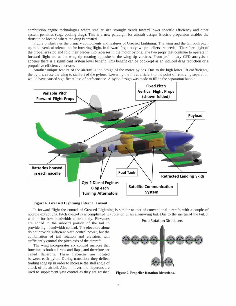
Figure 6 illustrates the primary components and features of Greased Lightning. The wing and the tail both pitch up into a vertical orientation for hovering flight. In forward flight only two propellers are needed. Therefore, eight of the propellers stop and fold their blades into recesses in the motor pylons. The two props that continue to operate in forward flight are at the wing tip rotating opposite to the wing tip vortices. From preliminary CFD analysis it appears there is a significant system level benefit. This benefit can be bookkept as an induced drag reduction or a propulsive efficiency increase.
Another unique feature of the aircraft is the design of the motor pylons. Due to the high loiter lift coefficients, the pylons cause the wing to stall aft of the pylons. Lowering the lift coefficient to the point of removing separation would have caused significant loss of performance. A pylon design was made to fill in the separation bubble.
Figure 6. Greased Lightning Internal Layout.
In forward flight the control of Greased Lightning is similar to that of conventional aircraft, with a couple of notable exceptions. Pitch control is accomplished via rotation of an all-moving tail. Due to the inertia of the tail, it will be for low bandwidth control only. Elevators are added to the inboard portion of the tail to provide high bandwidth control. The elevators alone do not provide sufficient pitch control power, but the combination of tail rotation and elevators will sufficiently control the pitch axis of the aircraft.
The wing incorporates six control surfaces that function as both ailerons and flaps, and therefore are called flaperons. These flaperons are located between each pylon. During transition, they deflect trailing edge up in order to increase the stall angle of attack of the airfoil. Also in hover, the flaperons are used to supplement yaw control as they are washed
Figure 7. Propeller Rotation Directions.

8
in the propeller slipstream. In hover, the vehicle is controlled like most quad copters. Pitch and roll control are accomplished via thrust
modulation of the props. Yaw control is accomplished by modulating the thrust of the clockwise versus counter clockwise propeller rotation. Figure 7 shows the propeller rotation directions. At the wing tips, the propellers rotate counter to the wing tip vortex. The vehicle has five points of contact with the ground. This provides a wide landing gear stance in order to maximize the tip over angles of the vehicle. The five points of contact are: lower vertical tail, each wing tip pylon, and two landing skids that extend out from the nose. This will provide the vehicle with the ability to robustly land and take off for off-airport operations.
The tail is made up of 3 panels: Inboard horizontal, middle 30 degree dihedral and outboard vertical.
V. Analysis Methods A more accurate trajectory analysis method was developed than the Brequet endurance equation listed above,
resulting in a time-step-based trajectory analysis tool. This code simulates the fuel burn in every segment of the actual flight profile to compute the total fuel burn as the vehicle flies from departure location to its destination. The code does have a simplifying assumption that there is zero acceleration in each of the flight profile’s phases. This is a reasonable assumption considering the largest source of error is the vehicle transition from vertical to horizontal flight and vice versa. However, the transition takes approximately 20 seconds and uses a negligible amount of energy relative to the 24-hour flight profile.
The mission analysis code is integrated into a vehicle sizing code to determine the gross weight of the vehicles. An initial guess for the MTOW is input by the user so that the tool can size the vehicle. Then, the mission analysis code simulates the specified flight profile. If the vehicle fuel is insufficient, the MTOW is increased, the vehicle is resized, and the flight profile is re-evaluated. This process is repeated in the code until the vehicle converges. These codes were written as Matlab routines to permit ease of development and use. The vehicles were hand optimized to find their ideal wing loading via the author modifying the input file and rerunning the code across multiple sensitivity runs.
The propulsion system performance and weight estimations were assumptions that were entered into the analysis codes, but the aerodynamic performance was computed. Drag polars were generated from conceptual geometry and wetted areas of each vehicle concept. XFLR57, an open-source vortex lattice tool that combines Mark Drela’s AVL and XFOIL tools, was used to compute the wing profile and induced drag. The wetted areas were utilized in combination with handbook methods to perform the drag buildup. More detail on this process can be found in reference 8.
VI. Sizing Results The tools, the analysis, and the assumptions that are described above were used to size the vehicles. Table 1
shows the results of the analysis. A fourth concept also investigated, but not listed in table 1, is the retracting rotor concept. This concept was carried as a technology development effort, but was not mature enough for sizing analysis or inclusion in the concept down selection process. See below for more information on the retracting rotor concept, and the unique technologies developed to provide additional degrees of integration freedom in future VTOL aircraft design studies.

9
Table 1. Vehicle Sizing Results. Trifecta Dos Samara Split Wing Greased Lighting GTOW (lbs) 264 247 281 264 Cruise Span (ft) 19.90 20.0 20.53 20.0 Wing Area (sq ft) 26.40 29.06 28.10 29.1 Wing Loading (lbs / sq ft) 10.0 8.5 10.0 9.1 Aspect Ratio 15.0 13.77 15.0 13.6 Horizontal Tail Area (sq ft) 4.44 6.16 5.14 8.36 Vertical Tail Area (sq ft ) 3.94 4.44 4.41 4.30 L/D 20.0 19.5 20.4 19.6 Fuselage Length (ft) 12.25 12.5 10.5 11.0 VTOL Lift Disc Area (sq ft) 67.3 150.9 108.1 59.4 Disc-loading (lbs/sq ft) 4.0 1.64 2.6 4.5 Wetted Area (sq ft) (unsized) 112.8 128.9 114.9 156.5 VTOL Power Required (hp) 22.8 16.1 22.4 21.9 Dash Power Required (hp) 5.7 5.8 5.6 5.2 Loiter Power Required (hp) 3.1 2.8 3.1 3.1 Initial Loiter Speed (kts) 65 60 65 69
VII. 35% Sub-Scale Prototypes During this second phase of the study, 35% sub-scale prototypes were fabricated and tested. The primary reason
for their fabrication was to develop and validate the ability of the concepts to transition from hovering flight to vertical flight and back. The dynamics of this problem are difficult to model numerically, with large resulting uncertainties that may not permit differentiation between the concept transition performance. In addition, the uncertainty of the inputs to such an analysis is greater than the confidence required of the results. It was deemed less expensive and more accurate to fabricate and test flying prototypes.
In order to facilitate this research, a number of facilities were constructed or modified at NASA Langley. The first is a stationary hover rig with an integrated force and moment balance to measure the forces and moments generated by each prop/rotor. This was a facility that has been used for testing of quadcopter VTOL models and was modified to accommodate our vehicles. The second facility is an outdoor netted cage that is 70 feet long, 35 feet wide and 35 feet tall. Vehicles were tested in the ‘Safe Flight Facility’ in hover and initial phases of transition using an overhead tether and in free flight. The cage was required to keep the vehicle out of Federal Aviation Administration (FAA) airspace. Per the FAA, a cage is considered equivalent to flying indoors. The third facility is a 1400 foot highly tensioned Spectra zip line developed to test transition without crashing the vehicles. This zip line facility serves two purposes. First, when control of the vehicle is lost, the pilot simply closes the throttle, lets the vehicle fall and permits it to be caught by the zip line which avoids damage from contact with the ground. The second purpose is similar to the hover cage in that the vehicle remains tethered to the ground in order to avoid FAA airspace restrictions or the necessity of getting a Certificate of Authorization waiver (COA). This zip line was constructed using sailboat grade hardware and rigging. The friction of the runner is small enough to allow the vehicles to be flown in forward flight without appreciably affecting the flight characteristics.
Figure 8. Trifecta 35% Scale Prototype.

10
A. Trifecta Concept Figure 8 is a depiction of the initial concept for this prototype which achieved yaw control via slipstream control
of the elevators when they are deflected 90 degrees down. It was found that there was insufficient yaw authority, so the elevators were enlarged to approximately triple their original size. While this did provide sufficient yaw authority, the increased wetted area would no longer allow the full scale vehicle to meet the efficiency requirements. It was decided to gimbal the rear motors laterally in order to provide yaw control in hover. Thrust vector control was found to be vastly more effective than slipstream control. Yawing moment generated by ~30 degrees of deflection of the large elevators was equivalent to ~3 degrees of gimbal of the rear motors. An unanticipated shortcoming of this concept was the need to ballast the nose in order to move the CG to the correct location, due to the retrofit nature of the spiral development of this vehicle. The full scale vehicle will not have this problem because the weight of the diesel engine will be in the front of the vehicle, instead of merely the lightweight electric motor utilized at the sub-scale size.
The Trifecta has been the focus of developmental effort for the controls group involved with this project. This was due to the Trifecta sub-scale concept being developed in a much more rapid fashion, due to the straightforward and low risk nature of this concept. The control system development involved collecting system ID flight data in hover, to determine the responses to movement of each motor throttle. A full control allocation scheme was developed for this vehicle that performs a summation of forces and moments at any flight condition. The result is a pilot input yields uncoupled motion of the vehicle. Much of the control system development involved establishing processes that would be easily applied to any subsequent concept, independent of the specific configuration layout.
B. Split Wing Concept The Split Wing prototype was fabricated with three wings. The first is a wing that models its forward flight configuration only; Figure 9 is depicting this vehicle. A pusher motor was added to the tail; this motor was used only for the forward flight testing of the vehicle. This wing has the planform of the wing in cruise, but does not have the wing motors in order to reduce the prototype’s weight. It is analytically possible to scale the inertias to account for the wing motors. The second wing fabricated is the hover capable wing. See Figure 10 for a picture of the split wing taken at the completion of a hover thrust test. For simplicity, this wing does not include the portion of the wing outboard of the motor support booms. The third wing under fabrication will be capable of the full articulation between hover and cruise configuration. Unfortunately, due to resource limitations a control system for this vehicle has not been developed.
Figure 9. Split Wing 35% Scale Prototype in Forward Flight Configuration.
Figure 10. Split Wing 35% Scale Prototype in Hover Configuration.
Assuming the structural dynamics are resolved, the authors have a high degree of confidence in the feasibility of this concept, with this vehicle likely exhibiting the most robust transition control and the quietest operation in hover, transition and forward flight.
C. Dos Samara Concept The Dos Samara was initially a significantly different configuration as depicted in Figure 11. The initial design
was intended to avoid the requirement for monocyclic. This was accomplished by adding small lift propellers on a V-tail. The main rotors were positioned forward of the CG. The inboard portion of the wing was swept forward and the outboard portion of the wing was swept aft in order to locate the main rotors in front of the CG and keep the aerodynamic center of the vehicle from being too far forward. Pitch control was accomplished via thrust modulation

11
on the rear lift propellers. Roll control was accomplished via differential collective of the main propellers. The rear lift propellers are canted outward. Yaw control was achieved via differential thrust modulation of the rear lift propellers. After fabrication of the prototype and initial flight testing two significant shortcomings of this configuration were discovered. Sizable resources were focused on modifying the configuration in order to shift the CG forward. The fact remains that having three propellers and motors in the tail and zero propellers and motors in the nose will always result in the CG to being too far aft. For these reasons, it was determined that the configuration needed to change in order to accommodate these concept shortfalls. The current Dos Samara configuration described in the prior section is currently being pursued and has not finished fabrication.
D. Retracting Rotor A fourth concept that has great potential but at a low technology readiness level (TRL) is the retracting rotor.
This concept has not had any sizing or performance analysis performed on it because a better estimate of the overall system weight needs to be developed first. Assuming the weight of the retracting rotor is reasonable, the concept would have the best performance of all the vehicle configurations assessed. The large diameter low disc-loading rotor would be the quietest, and have the lowest power required in hover. With the ability of the rotor to completely retract into the fuselage, the configuration is also the lowest drag solution – which would make it the best performing concept in forward flight as well. (See Figure 12 for a retracting rotor vehicle concept sketch.)
Figure 12. Retracting Rotor Vehicle Concept.
Historically there have been many unsuccessful attempts to implement a retracting rotor. Most employed fabric or telescoping blades in order to allow them to stow compactly. The fabric designs never performed well due to the fabric airfoils luffing, and their inability to be torsional stiff enough to provide cyclic control of the blades. Attempts at telescoping blades have tended to be mechanically complicated and heavy.
Figure 11. Dos Samara Initial Concept.

12
The current concept employs rigid airfoil segments that can fold up in an accordion-like manner, or roll up around a spindle inside the hub. When the retracting rotor is fully extended, it is rigid enough to employ collective and cyclic control in manner identical to conventional helicopters. The retracting rotor blade is broken up into multiple segments that when extended lock together to form a torsional stiff blade. There is a continuous Kevlar strap running the length of the blade that serves as the primary load path.
A set of prototype 35% scale retracting rotor roll-up blades with hinges which allow the blades to roll up was fabricated. The prototype roll-up blades also incorporate aluminum tangs and pockets at the segment interfaces. Centrifugal force from rotation is required to keep the blades from folding downward when extended.
Initial spin testing of the prototype roll-up blades showed good torsional stiffness – adequate for conventional cyclic rotor control. Figure 13 includes some in-work fabrication pictures for these blades which highlight some of the key design features. Figure 14 shows a prototype hub design that could be used with roll-up retracting rotor blades.
Figure 13. Retracting Rotor roll-up blade in-work fabrication pictures.
Figure 14. Retracting Rotor roll-up blade hub design.
Prototype retracting rotor blades being fabricated for the fold-up storage approach incorporate the same metal tang/pocket segment interfaces and hinges as the roll-up design. The difference is that the hinges alternate between the upper and lower surfaces – so the blades can fold up in an accordion or scissoring-gate manner, as shown in

13
Figure 15. The individual blade segments are fabricated starting from a set of commercially available hobbyist Radio Control (RC) helicopter kit blades. Part of the lead-filled leading edge area of the kit blades is machined away and replaced with contoured steel links that are hinged in the opposite direction from the aft composite portions of the blades. When the blades are partially extended or retracted, these steel links rotate in the opposite direction from the main blade, creating the scissor-gate pattern shown in the front view of Figure 15. Links consisting of the entire leading edge will fold up into the smallest volume, but will produce a lot of flow disruption and drag during blade extension or retraction.
Figure 15. Conceptual sketches for Retracting Rotor fold-up blade design.
A cable running along the centerline at about quarter-chord is used to control the extension and retraction of the blades. Centrifugal force on the rotating blades will extend the blades as far as the cables allow. Small worm-gear drive motors located near the hub center will wind up the cables to retract the blades – or wind out the cables to extend them. The scissor-gate structure will keep the blades from folding down when they are not rotating. When the blades are fully extended, the presence of Kevlar hinges at both the upper and lower surfaces of the airfoil will prevent the overall blades from folding up or down, even in the absence of centrifugal force from rotation. (At any given joint the leading edge hinge will only allow rotation in one direction, while the main blade hinge will only allow rotation in the opposite direction – so the blade will be mechanically locked against rotation at the joints.) Figure 20 shows a cross section of a commercial RC helicopter kit blade – with overlays indicating the location of the leading edge link and main blade Kevlar hinges. (Note that this figure is showing the larger link design, where the link includes almost the entire leading edge area.)

14
Figure 16. Location of Kevlar hinges for one joint between segments of a Retracting Rotor fold-up blade.
If the hub rotation is stopped with the retracted blade stacks oriented fore and aft, the hub can then be retracted down into the fuselage to fully stow the blades. (Extending the hub up prior to deploying the retracting rotor blades was previously included as part the vehicle conceptual design to clear the SatComm.)
The set of 35% scale retracting rotor blades incorporating the fold-up storage approach will be mounted on a commercial RC helicopter kit for ground and flight testing.
E. Greased Lightning The Greased Lightning prototype is a dimensionally
scaled prototype. It was decided to not dynamically scale this prototype because it would not leave the vehicle with a useful payload fraction. The intent of the prototype is to perform a demonstration of the flight profile, but not to build an aerodynamic database of the full scale vehicle.
In phase III of this study more resources were applied to the project. Therefore the prototype is being built and designed to a higher level of fidelity. Figure 17 is a screen capture of the Pro Engineer (ProE) model and Figure 18 illustrates the progress of the fabrication of the airframe.
With this higher level of resources being applied to the project two additional risk reduction tasks that were not previously performed are now being performed. First is a wind tunnel test to build an aerodynamic database of the vehicle in hover, transition and forward flight. Attempting to design the flight control systems without an aerodynamic database has proven to be very difficult. The second additional task being performed is a six degree of freedom simulation. The wind tunnel test aerodynamic data and mass properties from the ProE model will provide the data to build the simulation from. Having this simulation will enable the control designers to perform their control design before flight testing begins. This will vastly increase the likelihood of achieving a successful transition from hover to forward flight and back.
VIII. Conclusion This study investigated four VTOL aircraft concepts, which were developed, analyzed and tested through rapid
prototyping to diversify the risk across highly differentiated concept paths. The Trifecta’s risks are dominated by uncertainty in the weights and performance, but are a straight forward approach to meeting the requirements. The Spilt Wing’s primary risk is the conversion efficiency of the series hybrid propulsion system, but it will achieve the most robust transition corridor and cleanest configuration from a cruise drag and noise perspective. The Dos Samara’s risk is related to the mono bladed rotor system. Electrically syncing the left and right rotor as well as stopping the rotors in the proper position has been a more difficult task than originally anticipated, however it has not proven to be impossible. This vehicle will have the lowest disc-loading and takeoff weight of the three sized vehicles, assuming the compact and low drag hubs can be developed at full-scale. The fourth concept, the retracting
Figure 17. Pro Engineer Model of Greased Lightning.
Figure 18. Current Fabrication Progress.

15
rotor, is viewed as a low Technology Readiness Level (TRL) concept and was not sized due to its lack of mature characteristics. The risk associated with this concept is the retracting and rolling up of the rotor without jamming and the potential weight associated with the hub mechanism. The potential benefit of this concept is that it would provide the best of both worlds; both a large low disc-loading rotor for hover and a clean cruise configuration with minimal VTOL components exposed, with re-use of the structure for both purposes.
In the third phase of this study, using the lessons learned from the prototypes built in the second phase of this project, the Greased Lightning configuration is being developed. First flights of this configuration will begin this summer.
For this set of long endurance plus VTOL capable requirements, a hybrid-electric propulsion system is superior to a conventional propulsion system where an engine directly turns a propulsor. The amount of power that is needed to lift the vehicle off the ground in hover is vastly greater than the power that is needed for cruise. Electric motors have a much better power-to-weight ratio than internal combustion motors. The downside to electric propulsion is the battery weight, but the power that is required for takeoff is only needed for a short time; therefore, it is only a small amount of energy, relative to the total energy required of the flight profile. Consequently, a relatively small amount of battery weight is needed. Overall electric propulsion is a game changing technology for VTOL aircraft because it enables the VTOL capability with high cruise efficiency and low community noise operations in all phases of flight.

16
Appendices
A. Trifecta Forward Flight Four View
B. Trifecta Hovering Flight Four View

17
C. Split Wing Forward Flight Four View
D. Split Wing Hovering Flight Four View

18
E. Dos Samara Forward Flight Four View
F. Dos Samara Hovering Flight Four View

19
G. Retracting Rotor Forward Flight Four View
H. Retracting Rotor Hovering Flight Four View

20
I. Greased Lightning Forward Flight Four View
J. Greased Lightning Hovering Flight Four View

21
References 1Sklar, M., Brabant, E., “Boeing A160T Humming Bird Overview,” Boeing Defense, Space & Security, St. Louis, MO, 2012
http://www.boeing.com/bds/phantom_works/hummingbird/docs/hummingbird_overview.pdf 2Fredericks, W. J., “Conceptual Design of a Vertical Takeoff and Landing Unmanned Aerial Vehicle with 24-hr Endurance,”
AUVSI Unmanned Systems Conference, Denver, CO, 2010 3Ayers, Ferguson, “Ultra-Endurance Unmanned Aerial Vehicle (UE-UAV) Heavy-Fuel Engine (HFE) Project Final Report”,
NAVAIR Report NAWCWD TP 8765, July 2012. 4Anonymous, “Envia Hits 400 W*hr/kg Target with Li-ion Cells”, http://www.greencarcongress.com/2012/02/envia-
20120227.html. 5GS Engineering Incorporated, http://gsehfe.com/ 6Fredericks, W. J., “Aircraft Conceptual Design Using Vehicle Sketch Pad,” 48th AIAA Aerospace Sciences Meeting,
Orlando, FL, 2010 7http://www.xflr5.com/xflr5.htm 8Fink, D. A., Hawkey, T. J., Gaudreau, M. P.J., “HeliflapTM, AN ELECTROMAGNETIC ACTUATOR FOR INDIVIDUAL
BLADE CONTROL,” Diversified Technologies, Inc., Bedford, MA