Embed Size (px)
Citation preview
BENEFICIATION OF IRON ORE
A THESIS SUBMITTED IN PARTIAL FULLFILLMENT OF THE
REQUIREMENTS FOR THE DEGREE OF
Bachelor of Technology
In
Mining Engineering
By
SANJAY KUMAR AGARWAL
110MN0569
SUDHANSHU KUMAR
110MN0593
DEPARTMENT OF MINING ENGINEERING
NATIONAL INSTITUTE OF TECHNOLOGY
ROURKELA – 769008
2013-2014
BENEFICIATION OF IRON ORE
A THESIS SUBMITTED IN PARTIAL FULLFILLMENT OF THE
REQUIREMENTS FOR THE DEGREE OF
Bachelor of Technology
In
Mining Engineering
By
SANJAY KUMAR AGARWAL
110MN0569
SUDHANSHU KUMAR
110MN0593
Under the guidance of
Dr. B.K. Pal
DEPARTMENT OF MINING ENGINEERING
NATIONAL INSTITUTE OF TECHNOLOGY
ROURKELA – 769008
2013-2014
~ I ~
National Institute of Technology, Rourkela
CERTIFICATE
This is to certify that the thesis entitled “Beneficiation of Iron Ore” submitted
by Sri Sanjay Kumar Agarwal (Roll No. 110MN0569) and Sri Sudhanshu
Kuamr (Roll No. 110MN0593) in partial fulfilment of the requirements for the
award of Bachelor of Technology degree in Mining Engineering at the National
Institute of Technology, Rourkela is an authentic work carried out by him under
my supervision and guidance.
To the best of my knowledge, the matter embodied in the thesis has not been
submitted to any other University/Institute for the award of any Degree or
Diploma.
Date:
Dr. B.K Pal
Department of Mining Engineering
National Institute of Technology
Rourkela – 769008

~ II ~
ACKNOWLEDGEMENT
First of all, I would like to express my deep sense of respect and gratitude towards my
advisor and guide Dr. B.K. Pal, who has been the guiding force behind this work. I am
greatly indebted to him for his constant encouragement, invaluable advice and for
propelling me further in every aspect of my academic life. I consider it my good
fortune to have got an opportunity to work with such a wonderful person, not just
professionally but personally as well.
I thank each and every faculty of the Department of Mining Engineering, National
Institute of Technology, Rourkela from the bottom of my heart. They have been great
sources of inspiration, knowledge and encouragement throughout the course of my
Bachelor’s Degree.
Last but not the least, my sincere thanks to all my friends who have patiently extended
all sorts of help for accomplishing this dissertation.
Date: SANJAY KUMAR AGARWAL
SUDHANSHU KUMAR
~ III ~
ABSTRACT
Wide reserves of iron ore is found in India. Due to the high quality of iron ore available in
India, large deposits of Banded Haematite Jasper (BHJ) are left unused because of the
presence of silica in unwanted quantity.
ROM is put through washing to remove the clayey matter due to the presence of alumina and
silica in iron ore leading to slime generation which are disposed of in tailing ponds. Slime in
these tailing ponds contains iron values in the range of 45-60%. Appropriate beneficiation
process has to be advanced to reduce the waste generation in mines and for the sustainable
growth of the iron ore industry some.
Major reason for difficulty in beneficiation of BHJ is revealed from characterization studies
which show the intergrowth of haematite and quartz. Presence of Kaolonite is proved with
the aid of mineralogical studies. For the separation of alumina from iron ore Beneficiation
studies have to be carried out.
~ IV ~
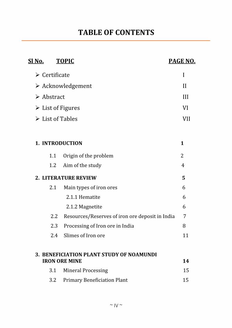
TABLE OF CONTENTS
Sl No. TOPIC PAGE NO.
Certificate I
Acknowledgement II
Abstract III
List of Figures VI
List of Tables VII
1. INTRODUCTION 1
1.1 Origin of the problem 2
1.2 Aim of the study 4
2. LITERATURE REVIEW 5
2.1 Main types of iron ores 6
2.1.1 Hematite 6
2.1.2 Magnetite 6
2.2 Resources/Reserves of iron ore deposit in India 7
2.3 Processing of Iron ore in India 8
2.4 Slimes of Iron ore 11
3. BENEFICIATION PLANT STUDY OF NOAMUNDI IRON ORE MINE 14
3.1 Mineral Processing 15
3.2 Primary Beneficiation Plant 15
~ V ~
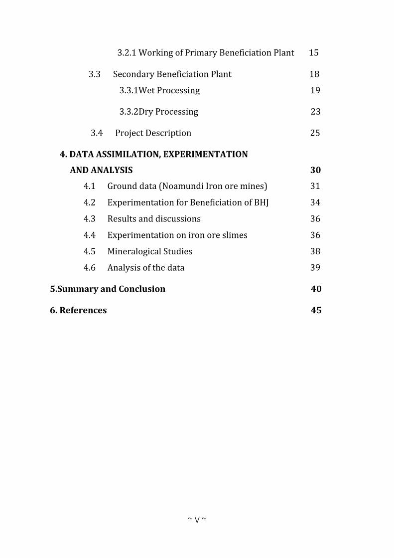
3.2.1 Working of Primary Beneficiation Plant 15
3.3 Secondary Beneficiation Plant 18
3.3.1Wet Processing 19
3.3.2Dry Processing 23
3.4 Project Description 25
4. DATA ASSIMILATION, EXPERIMENTATION
AND ANALYSIS 30
4.1 Ground data (Noamundi Iron ore mines) 31
4.2 Experimentation for Beneficiation of BHJ 34
4.3 Results and discussions 36
4.4 Experimentation on iron ore slimes 36
4.5 Mineralogical Studies 38
4.6 Analysis of the data 39
5.Summary and Conclusion 40
6. References 45
~ VI ~
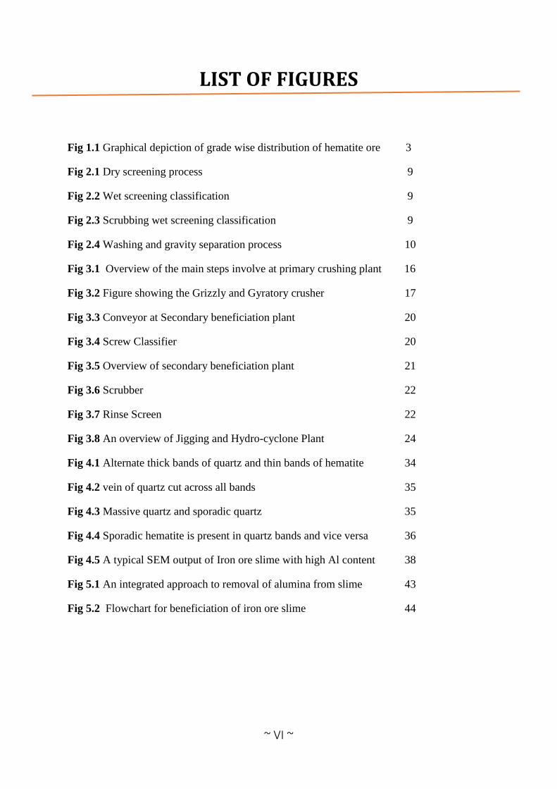
LIST OF FIGURES
Fig 1.1 Graphical depiction of grade wise distribution of hematite ore 3
Fig 2.1 Dry screening process 9
Fig 2.2 Wet screening classification 9
Fig 2.3 Scrubbing wet screening classification 9
Fig 2.4 Washing and gravity separation process 10
Fig 3.1 Overview of the main steps involve at primary crushing plant 16
Fig 3.2 Figure showing the Grizzly and Gyratory crusher 17
Fig 3.3 Conveyor at Secondary beneficiation plant 20
Fig 3.4 Screw Classifier 20
Fig 3.5 Overview of secondary beneficiation plant 21
Fig 3.6 Scrubber 22
Fig 3.7 Rinse Screen 22
Fig 3.8 An overview of Jigging and Hydro-cyclone Plant 24
Fig 4.1 Alternate thick bands of quartz and thin bands of hematite 34
Fig 4.2 vein of quartz cut across all bands 35
Fig 4.3 Massive quartz and sporadic quartz 35
Fig 4.4 Sporadic hematite is present in quartz bands and vice versa 36
Fig 4.5 A typical SEM output of Iron ore slime with high Al content 38
Fig 5.1 An integrated approach to removal of alumina from slime 43
Fig 5.2 Flowchart for beneficiation of iron ore slime 44
~ VII ~
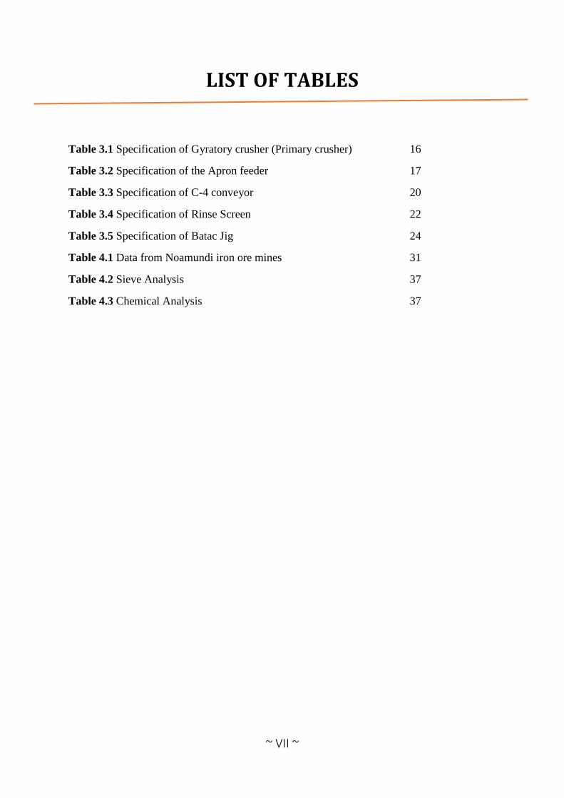
LIST OF TABLES
Table 3.1 Specification of Gyratory crusher (Primary crusher) 16
Table 3.2 Specification of the Apron feeder 17
Table 3.3 Specification of C-4 conveyor 20
Table 3.4 Specification of Rinse Screen 22
Table 3.5 Specification of Batac Jig 24
Table 4.1 Data from Noamundi iron ore mines 31
Table 4.2 Sieve Analysis 37
Table 4.3 Chemical Analysis 37
1
INTRODUCTION
CHAPTER-1
2
1. INTRODUCTION
1.1 ORIGIN OF THE PROBLEM:
Basic raw material for iron and steel industry is Iron ore which leads to our growing
economy. India has huge reserves of quality iron ore which can fulfil the growing demand for
domestic iron and steel industry as well as sustain large external trade.
The most important iron ore types found in India are hematite and magnetite. Nearly 61% of
hematite ore deposits are found in the eastern part of India and 82% of magnetite ore deposits
occur in southern part of India, especially in the state of Karnataka.
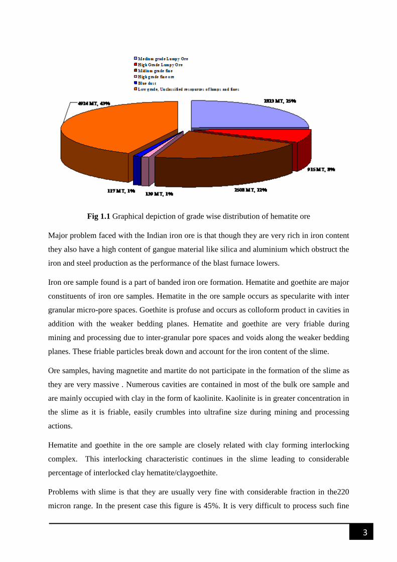
India possesses around hematite resources of 11,464 million tons of which 6,013 million
tonnes are reserves and 5,442 million tonnes are residual resources .About 2,842 million tons
(25.8%) are medium grade lumpy ore resources while 945 million tons (8.4%) are high-grade
lumpy ore. Out of the fines resources about 2,543 million tons (22%) are medium grade ore,
39.9 million tonnes (1%) are high-grade and 17.7 million tons (1%) resources are of blue dust
range. The residual are low grade, unclassified resources of lumps and fines or high, medium,
low or unclassified grades of lumps and fines mixed.
The cut-off grade for estimating the hematite resources has been taken as 57% Fe. If the cut-
off grade is reduced to say 43% Fe, the iron ore resources will increase considerably and thus
bearable utilization of iron ore can be achieved.
3
Fig 1.1 Graphical depiction of grade wise distribution of hematite ore
Major problem faced with the Indian iron ore is that though they are very rich in iron content
they also have a high content of gangue material like silica and aluminium which obstruct the
iron and steel production as the performance of the blast furnace lowers.
Iron ore sample found is a part of banded iron ore formation. Hematite and goethite are major
constituents of iron ore samples. Hematite in the ore sample occurs as specularite with inter
granular micro-pore spaces. Goethite is profuse and occurs as colloform product in cavities in
addition with the weaker bedding planes. Hematite and goethite are very friable during
mining and processing due to inter-granular pore spaces and voids along the weaker bedding
planes. These friable particles break down and account for the iron content of the slime.
Ore samples, having magnetite and martite do not participate in the formation of the slime as
they are very massive . Numerous cavities are contained in most of the bulk ore sample and
are mainly occupied with clay in the form of kaolinite. Kaolinite is in greater concentration in
the slime as it is friable, easily crumbles into ultrafine size during mining and processing
actions.
Hematite and goethite in the ore sample are closely related with clay forming interlocking
complex. This interlocking characteristic continues in the slime leading to considerable
percentage of interlocked clay hematite/claygoethite.
Problems with slime is that they are usually very fine with considerable fraction in the220
micron range. In the present case this figure is 45%. It is very difficult to process such fine

4
particles. This is replicated in the fact that though a pellet grade concentrate could be
obtained the yield is a mere 27%.
1.2 Aim of the study:
The aim of this project is to propose methods for utilization of low grade iron ore especially
Banded hematite Jasper (BHJ) and slimes. This is met by the following specific objectives:
Study of field data collected from NIM(noamundi iron ore mines)
Study the characterization data of BHJ and study the methods of up gradation by
seeing to the characterization results.
Proposal of methods for beneficiation of iron ore slimes.

5
LITERATURE REVIEW
CHAPTER-2
6
2. LITERATURE REVIEW
2.1 Main types of iron ores
Most prominent ore found in India are mainly hematite and magnetite. Among these,
hematite is considered to be most important. Iron ore is used in production of pig iron which
is further used in production of steel other uses of iron ore are like industrial finishes,
polishing compounds and sponge iron industries. Iron ore belongs to Precambrian stage and
its deposit is present in massive, laminated, friable and also in powdery form. Its major
deposits are in Jharkhand, Orissa, Chhattisgarh, Karnataka and Goa States.
2.1.1 Hematite:
It is most important iron ore mineral main source for industries. Its composition is Iron Oxide
and sometimes slight amount of titanium. Its name comes from the Greek word for blood,
haima, because of its reddish colour. Crystals occurs in thin plates, as well as bundles of
small micaceous plates, and in thin splinters. Most commonly massive, mammilary,
botryoidal, reniform, oolitic, stalactitic, and radiating. Scalenohedral and rhombohedral
crystals occur, although infrequently, and dendritic and rosette forms are also found.
Hematite may also form as a pseudomorph of other minerals, especially as octahedral crystals
of Magnetite. Striking features are reddish streak, hardness, crystal habits and Para
magnetism. It becomes strongly magnetic when heated. Its specific gravity is 4.9 to 5.3 and
luster is metallic to dull. Hematite is weakly magnetic, but it has a variety called magnetite
which is found in many ore bodies in minute quantities having magnetic properties closely
related to those of magnetite. The content of iron in the ore and physical characteristics vary
from place to place in different types of ores.
2.1.2 Magnetite:
After hematite it is second most abundant Iron bearing ore. Black magnetic oxide of iron
crystallizing in the isometric system with hardness of 5.5 to 6.5. Magnetite ore is of little
value in its raw state, but it offers considerable advantages in its concentrated form. These
include providing a viable iron-making commodity for premium quality steel production. By
comparison, magnetite ore typically has much lower iron content when mined of between
7
25% and 40% Fe and in this form is unsuitable for steel making. The main iron mineral in
magnetite ore is the ferrous iron oxide magnetite (Fe3O4). Magnetite ore requires complex
processing to separate magnetite minerals from other minerals in the ore to produce an almost
pure magnetite concentrate with an iron content of between 68% Fe and 70% Fe that is highly
sought after by steel makers. It also occurs as a replacement product in sedimentary or
metamorphic rocks. It is found as placer deposits as ―black sand‖ in beach deposits and as
banded layers in metamorphic and igneous rocks.
2.2 Resources/Reserves of iron ore deposit in India
The iron ore deposits of India can be broadly divided in to the following six groups on the
basis of mode of occurrence and origin
Banded Iron Formations(BIF) of Pre-Cambrian Age
Sedimentary Iron Ore Deposits of Siderite and Limonitic Composition
Lateritic Ores derived from the Sub-Aerial Alternations
Apatite-Magnetite Rocks of Singhbhum Copper belt
Fault and Fissure Filling Deposits
Titanifereous and Vanadiferous Magnetites
Indian deposits of hematite belong to Pre-Cambrian Iron ore series and the ore is within the
Banded Iron Ore Formations (BIF) occurring in massive, laminated, friable and also in
powdery form. BIF mostly found in states of Jharkhand, Bihar, Orissa, Madhya Pradesh,
Chattisgarh, Maharastra, Karnataka, Goa and Tamil Nadu. most common names used in India
to designate BIF are Banded Hematite Jasper (BHJ) and Banded Hematite Quartzite (BHQ).
Different types of iron ore derived from banded hematite rocks met within the deposits of this
group are
Massive ore
Laminated ore
Blue dust.
8
The massive ores occur as massive bodies in which show non planar structures. The blue dust
is a form of very fine-grained powdery ore which consists loose crystals of hematite and
magnetite. The laminated ores though be mineralogicaly and chemically similar to massive
ores, but have planar structures, which may be spaced closely. Occurring as pockets in harder
ores it forms the major constituent at depth.
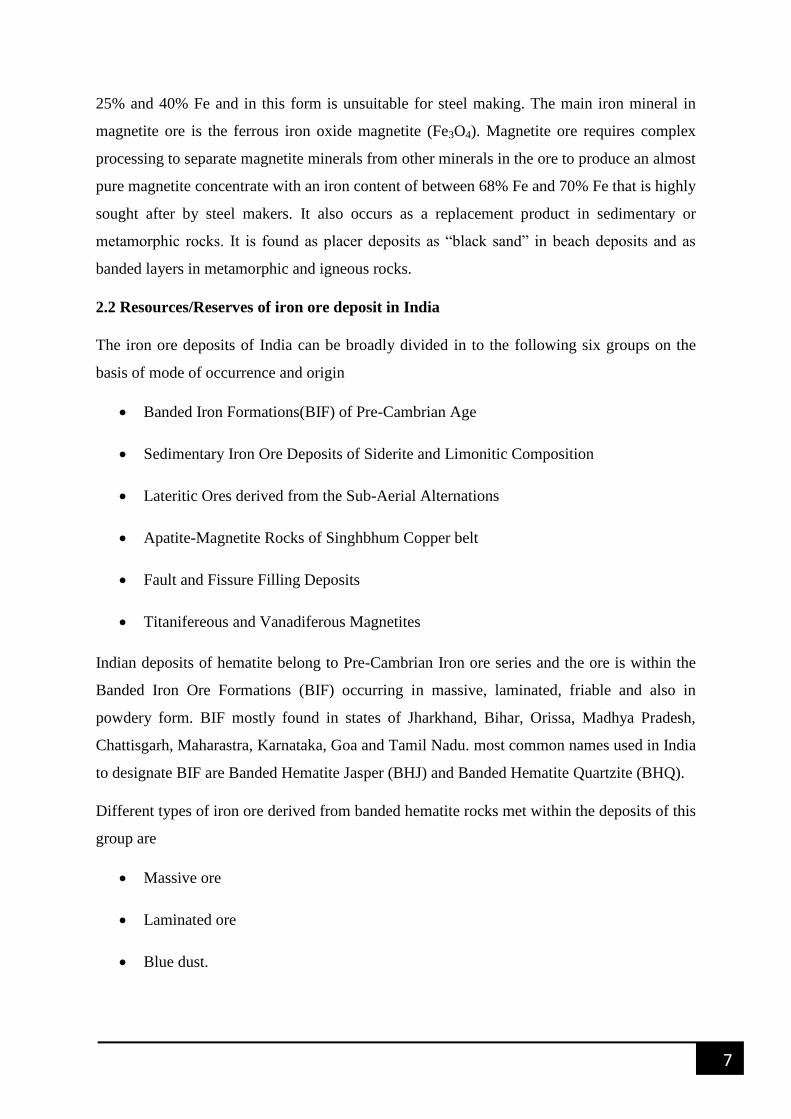
2.3 Processing of Iron ore in India
Iron processing depend mainly on the type of ROM ore feed and optimum product. Dry
screening into lumps and fines is practised for high quality flaky ore and blue dust, because,
if wet treatment is used, a substantial part of good quality material is rejected in the form of
slimes. Another advantage of dry screening is dry screened fines also retain ultra-fines
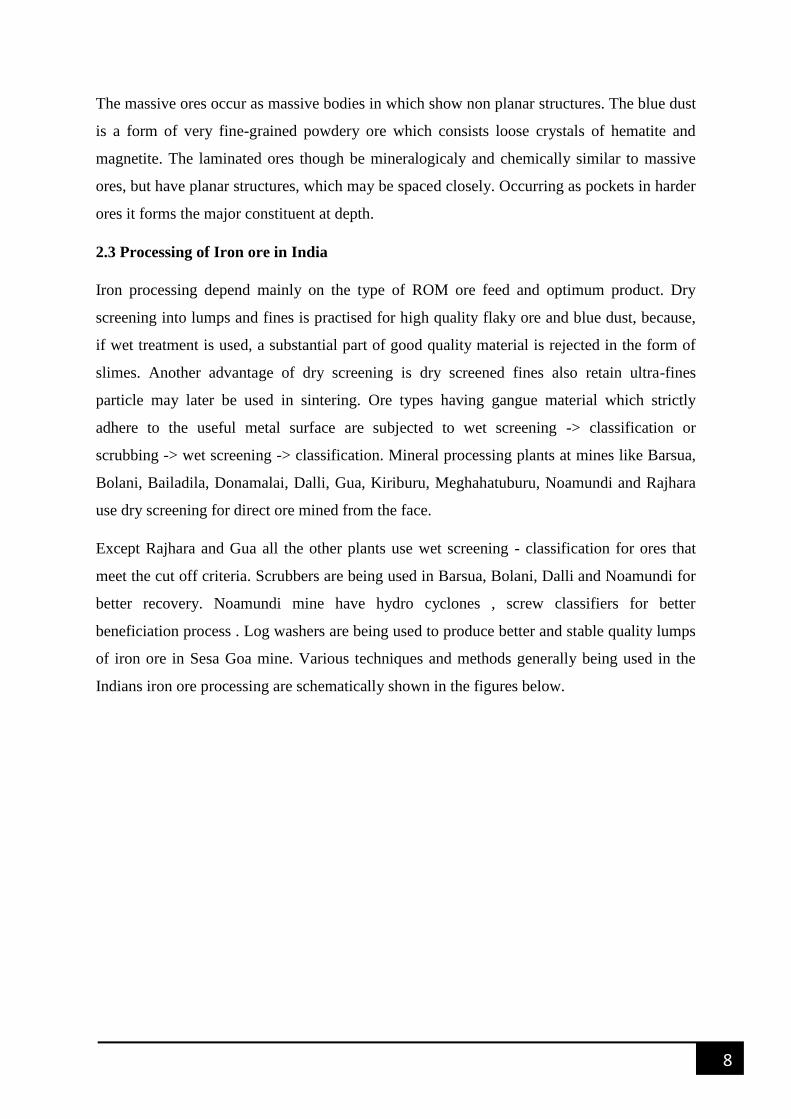
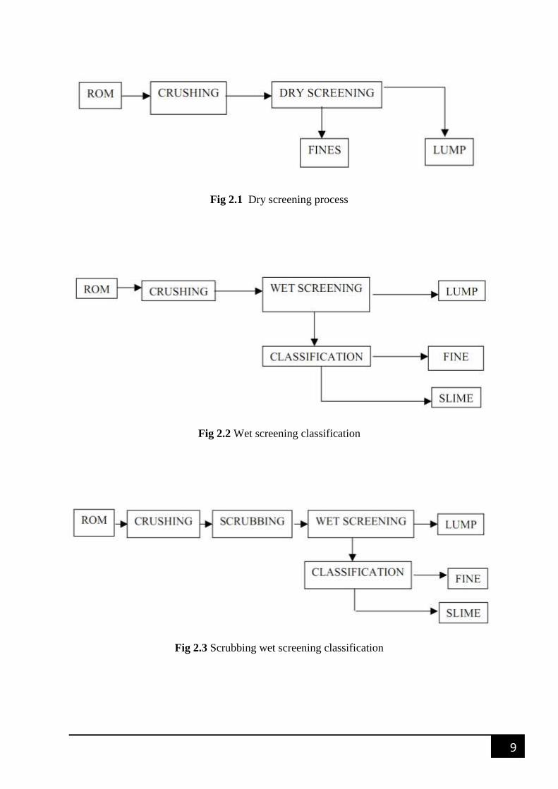
particle may later be used in sintering. Ore types having gangue material which strictly
adhere to the useful metal surface are subjected to wet screening -> classification or
scrubbing -> wet screening -> classification. Mineral processing plants at mines like Barsua,
Bolani, Bailadila, Donamalai, Dalli, Gua, Kiriburu, Meghahatuburu, Noamundi and Rajhara
use dry screening for direct ore mined from the face.
Except Rajhara and Gua all the other plants use wet screening - classification for ores that
meet the cut off criteria. Scrubbers are being used in Barsua, Bolani, Dalli and Noamundi for
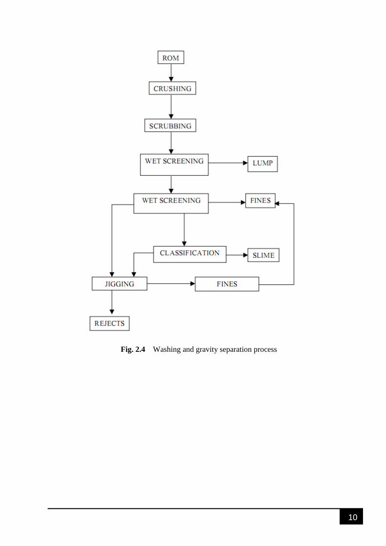
better recovery. Noamundi mine have hydro cyclones , screw classifiers for better
beneficiation process . Log washers are being used to produce better and stable quality lumps
of iron ore in Sesa Goa mine. Various techniques and methods generally being used in the
Indians iron ore processing are schematically shown in the figures below.
9
Fig 2.1 Dry screening process
Fig 2.2 Wet screening classification
Fig 2.3 Scrubbing wet screening classification
10
Fig. 2.4 Washing and gravity separation process
11
2.4 Slimes of Iron ore:
For improving quality and to reduce cost of production iron ore industries are demanding
high grade raw minerals. However, the ore being a non-renewable natural resource, the
reserve of good quality ore is depleting. Marginal to sub-marginal ore should be used to meet
the present as well as future requirements and avoid environment related problems. The
circumspect utilization of Iron ore can conserve high grade mineral resource. So today there
is need of sustainable development in iron ore mining that is need of present without
compromising the need of future generation. So it becomes vital to develop some technique
for beneficiation of unutilized low grade ore and ultra-fine material i.e. slime. Washing plant
data implies that generation of slime comprise of 30-35% of the total ore mined. Because of
lack of technology and its complex nature, a significant quantity of slime remains unused.
These slimes are dumped which causes environmental hazards. If pellets are produced
directly from such fines, they become high in alumina which is undesirable in Blast furnace
as high alumina content will adversely affect the pellet properties, typically measured by
Reduction Degradation Index (DRI) and Reducibility Index (RI). A drop in alumina content
can improve these properties and also reduce the coke consumption in Blast furnace. Tailings
contain harmful material like iron sulphide which is primary source for acid mine drainage.
Sedimentation test show that the tailings and the area required for tailing pond is around 3155
m2 in comparison to 10,000 m
2 obtained from the use of an empirical equation. It is estimated
that around 10 million tons of slimes are being generated every year in the processing of
hematite ore and lost as tailings containing around 48-62% of Fe. It is also very difficult to
evaluate the characteristics of these slimes where most of the particles are below 50 microns.
The generation of iron ore slimes in India is estimated to be 10-25% by weight of the.
Presently, because of lack of availability of efficient technology to process them and due to
difficult nature of the fines and slimes, a large amount of it is left still unused. Base on the
fact that iron ore production wills more than double and rise to at least 300 million tonnes
soon, finding suitable methods of safe disposal/utilization of slimes is indeed urgent. If we
look at the present quantity of the iron ore slimes that is being generated annually,
amalgamation of quantity of slimes, over the years the fact that slimes are available in ground
form and assaying that is reasonably high %Fe, it is natural that if beneficiated in a proper
way, these slimes can be considered a national resource rather than a waste. The alumina
content of the slimes, if brought to less than 2% Al2O3 in the beneficiated product will
12
Lead to better utilization of national resources
Achieve more mine output (enhanced production) with not much additional costs
Reduce environmental issues associated with storage and disposal of slimes and
Result in higher blast furnace and sinter plant productivity
In view of the above facts proper technology shall be adopted for processing of slimes to
recover iron ore values from them, this will be a step forward for conservation of mineral in
national interest. As particle size in slime is finer (<.15mm) so it will be easy to beneficiate
the slime without the use of any combination process.
In last twenty years importance is slowly tilting towards slime beneficiation and in addition to
the traditional methods of processing, enhanced gravity separators (EGS) such as Falcon,
Knelson concentrator are also being experimented with to beneficiate the Slimes. Now a
day’s novel method of beneficing iron ore slime is used via magnetic and gravity method of
separation.
Two distinct mineral constituent of Alumina in Indian iron ore slimes are gibbsite (hydrated
aluminium oxides) and kaolinite. Exact amount of alumina has not been quantified till date
according to liberation studies a significant portion of alumina is present in the liberated form
and so it is possible to separate them using physical methods.
Slag viscosity in blast furnace is increased due to high alumina content. This leads to increase
in metal loss in slag, increase in thermal requirement and thus makes the Blast furnace
operation more tough. To reduce alumina burden new technologies are adopted by steel
industries. Using pellets can reduce this burden.
All around the world Iron ores are being beneficiated including Kudremukh in India. Several
Methods such as
Spiral
Floatex density separators
Jigs
3 multi-gravity separator
13
Low and high intensity magnetic separator
Conventional as well as column flotation
Selective dispersion
Flocculation is all part of current industrial practice.
Present advances include Batacjigs, packed flotation column, packed column jigs and
centrifugal concentrators like Falcon Concentrator, Knelson Concentrator for the
beneficiation of iron ore slimes. At present Processing of hematitic ores is done in India,
however, does not involve any beneficiation except for rejection of silica for some alumina
occurs during washing and classification of crushed ores.
Recently two beneficiation plants have been set up to process sinter fines for value addition.
Essar is operating an 8 million tonnes per anum pellet plant in Visakhapatnam based on the
slimes and fines being pumped from NMDC’s Balladilla iron ore mine. The beneficiation
includes gravity separation (spirals) of the coarser portion after desliming it and high
intensity magnetic separation of the finer fraction.
Assay less than 2.5% by weight of added alumina and silica content is grounded to produce a
feed acceptable for the pelletization circuit is produced by the concentrator.
A technological development programme needed to define the appropriate Beneficiation
strategy for Indian iron ore deposits must include
(i) The mode of occurrence, alumina containing minerals association and liberation
characteristics.
(ii) A comparison of the separation efficiency of different unit operations for both
hematitegoethite/ kaolinite/gibbsite separation in view of recovery-grade plots (separation
Characteristics) and as a function of particle size
(iii) Preliminary techno-economic valuation of the various technology options for a typical
iron ore mine in the country.
14
BENEFICIATION PLANT STUDY
OF NOAMUNDI IRON ORE MINE
CHAPTER-3
15
3. BENEFICIATION PLANT STUDY OF NOAMUNDI
IRON ORE MINES
3.1 Mineral Processing
Noamundi processing plant processes ROM from Noamundi Iron Mine as well as from
adjoining Katamati iron mine. A part of the ROM ore is beneficiated by Wet process while
the other part of the ROM ore is beneficiated by the Dry process. In the Wet process, the feed
constitutes hard ore, soft ore and flaky ore, which is fed in pre-determined proportion while
in the Dry process; feed constitutes of flaky ore and blue dust. The secondary beneficiation
plant is consists of two processes:-
Dry Processing
Wet Processing
The Primary beneficiation plant consists of only a Gyratory crusher and from there the
material is transferred to the Secondary plant via conveyor belt method. The main objective
of the Primary beneficiation plant is the crushing of the ROM from the mines while the
main objective of the Secondary beneficiation plant is screening, crushing and washing.
3.2 Primary Beneficiation Plant
The Primary crushing system process produces iron ore of 170mm (input feed material for
secondary beneficiation system) with ROM quality scheduled by geological department. The
ROM is dumped into primary crusher having a capacity of 1800 TPH (54 inch Gyratory
crusher). The crushed ore (-200mm) in size is then stored in two separate primary stockpiles.
The crushed ore is then fed into two identical circuits for secondary processing.
3.2.1 Working of Primary Beneficiation Plant
ROM of -1200mm size is feed to primary crusher by Mining Department through 100T
dumper, -150mm size boulder gets screened through the grizzly, and the rest is being
crushed in the crusher. Normally the crusher gap (open side setting) is being set to
150mm to avoid any oversize material going to secondary crushing system. All crushed
16
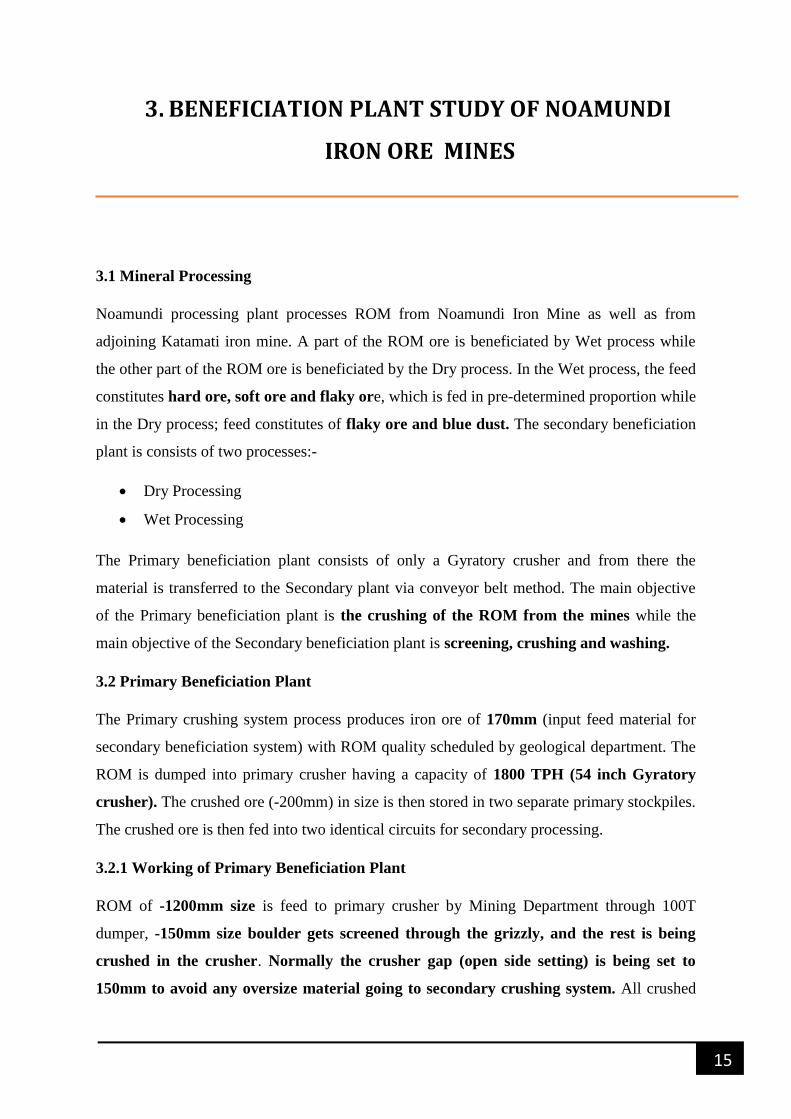
and grizzly-screened material goes directly through two apron feeders to C1 conveyor. C1
conveyor has integral tripper system for stocking the material in B & C primary surge pile
during crushing to minimize the dust emission, dust suppression for which dust extraction
system are installed. An overview of the basic steps involved in the processing of the ROM
ore is produced below in the figure: -
Fig 3.1 Overview of the main steps involve at primary crushing plant
Primary beneficiation mainly consists of following main components: -
Gyratory crusher: - Gyratory crushers are principally used in surface- crushing plants,
although a few currently operated underground. The gyratory crusher consists essentially of a
long spindle, carrying a hard steel conical grinding element, the head, seated in an eccentric
sleeve. The spindle is suspended from a spider and as it rotates, normally between 85-150
rev/min, it sweeps out conical path within the fixed crushing chamber, or shell, due to the
gyratory action of the eccentric. Generally in this model of gyratory crusher being used ¾
of the material is passed while ¼ material has to be removed sometime with the help of
crane or manually. Korrobond 65 Epoxi-based dampningsmassa for stenkrossas is used for
lining the core. The specification the Gyratory crusher used in the Primary beneficiation
plant-Noamundi is given below: -
Table 3.1 Specification of Gyratory crusher (Primary crusher)
MODEL CG-820
MAKE SANDVIK
17
WEIGHT 262T
CAPACITY 1600-3500MTPH
MAX FEED SIZE 1200mm
LUMP SIZE 130-200mm
MOTOR CAPACITY 450KW
V-BELT SIZE SPC 9500(16 NOs.)
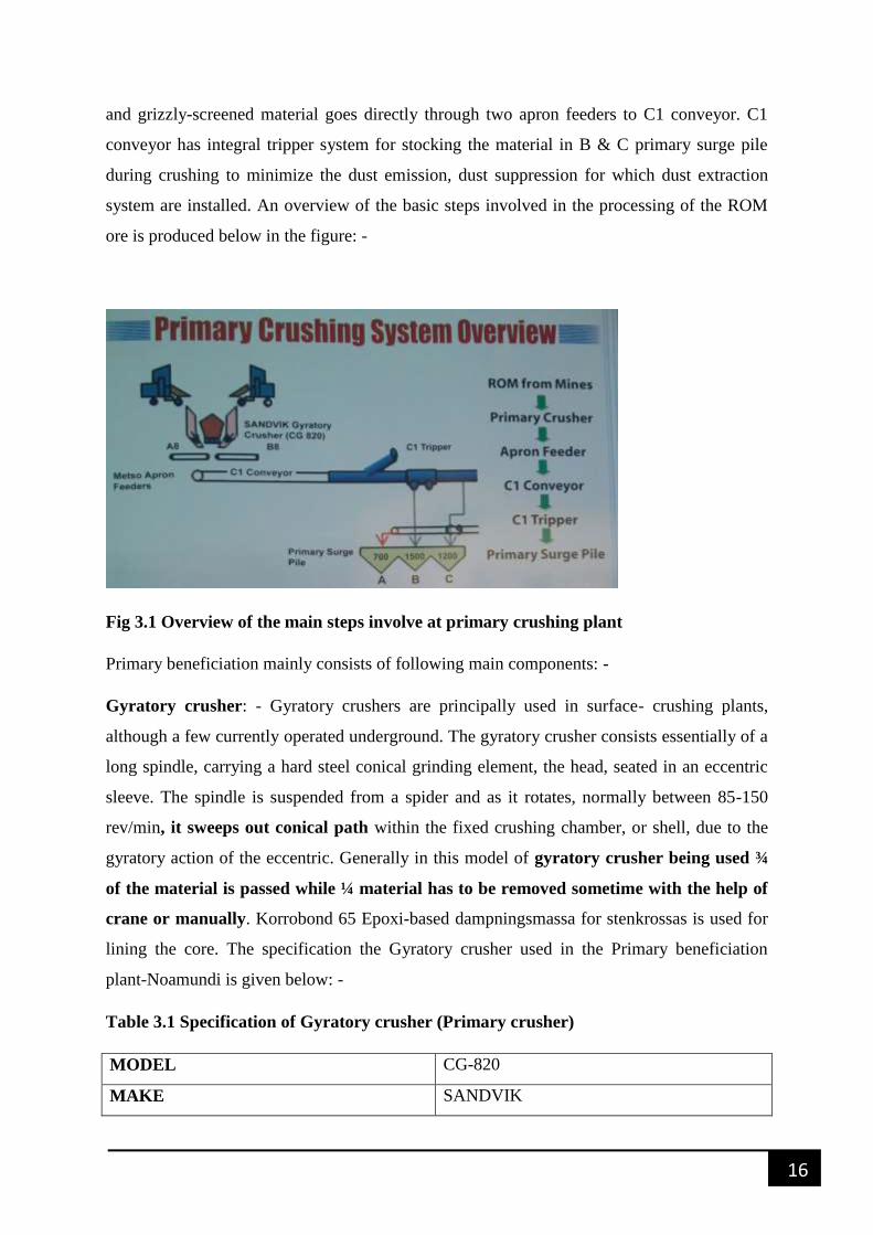
Grizzly: - Grizzlies are used for rough screening of coarse materials and often found in
crushing circuits. A grizzly is basically an inclined set of heavy bars set in a parallel manner.
Coarse material slides on the inclined surface of the bars material finer than the spacing
between the bars falls through. The Grizzlies can be vibrated to improve performance.
Fig 3.2 Figure showing the Grizzly and Gyratory crusher
Apron Feeder: - Apron feeder is used to transfer the material from the crusher to the belt
conveyor. The crushed ore from the Gyratory crusher is no directly to the conveyor since it
will have adverse impact on the belt and the belt might get damaged. Thus apron feeder is
used as an intermediate to transfer the material to the belt thus preventing the belt from any
damage. Specification of the Apron feeder is given in the table below: -
Table 3.2 Specification of the Apron feeder
MAKE METSO
CAPACITY 500-1200 TPH
LUMP SIZE 200-250 mm
VELOCITY 0.12m/sec
18
WIDTH*DEPTH 1.83*0.84 M
MOTOR 55KW * 1500RPM ,VVVF DRIVE
GEAR BOX BEVEL PLANETARY HELICAL REDUCTION GEAR UNIT
RATIO-365.87:1
INPUT
COUPLING
GEAR COUPLING , SIZE:-ED500
Hydro set Tank: - Hydro set tank is used to maintain the jack pressure.
Balancing cylinder: - Balancing cylinder consists of NO2 gas. The main function of the
balancing cylinder is to control the jack movement thus preventing any damage. Also id helps
in clearing the material that stuck into the crusher bottom opening.
C1 conveyor: - It is used to transport the material from the primary beneficiation plant to the
secondary plant. It is a centrally driven two drive arrangement.
Dust Collector: - It is used to collect the dust produced at the Apron feeder in the Primary
crushing system and then discharge it into the atmosphere.
3.3 Secondary Beneficiation Plant
Secondary Plant is consisting of mainly three parts in which the beneficiation of the sized ore
is done. In secondary plant the material is transported from the primary plant with the help of
C1 conveyor and is stored in primary surge-pile of capacities 700ton, 1500ton, 1200ton
respectively for A, B, C surge pile. Out of which Primary surge-pile A is used as input for
the production of LD and is dry circuit, while surge-pile B, C is wet circuit input feed. The
output of the three circuits is stored in three secondary surge-bins after processing from the
Jig and Hydro-cyclone plant. There are three secondary surge-bins of capacities 2000ton,
3000ton, 3000ton, respectively for circuits A, B, C. The main three parts of the secondary
beneficiation plant is: -
Wet Processing
Dry Processing
Jig and Hydro-cyclone Plant
19
3.3.1Wet Processing
““„Sized ore (-200mm) from the primary plant is stocked into two primary stockpiles of
capacity (1500ton and 1200ton) and then fed into two identical circuits for secondary
processing. Each secondary processing circuit consists of one secondary crusher which
crushes the material to -40mm size. The crushed product is then screened on a double deck
screen, with the top deck at +40mm and the lower deck at -10mm. The oversize (i.e. +40mm)
product from each of the secondary circuits is stored in a surge-pile from where it is fed to a
tertiary crusher arranged in a closed loop, to ensure minimum generation of oversize in the
sized ore. The -40mm +10mm fraction is recovered as sized ore. The -10mm fraction from
the secondary crushed product is sent to screw classifiers. The -10mm fraction of the tertiary
crushed product is recovered as Fines. In the screw classifier, the -10mm fraction from the
secondary crushed product is classified to yield two products viz. -10mm +0.15mm (as
underflow) and -0.15mm (as overflow). The coarser fraction (i.e. -10mm +0.15mm) is then
sent to a dewatering screen to drain off the excess moisture in the fines. The dewatering
screens have a 1mm aperture, where the coarser fraction of the screw classifier (+0.15mm) is
screened. The +1mm product after screening is sent for jigging while the finer fraction
(i.e. -1mm) collected from each of the three circuits along with the classifier overflow is
sent to the hydro-cyclones.‟””
In wet following are the main components: -
Cone Crusher [ Shot head cone crusher for circuit A and Standard cone crusher for
circuit B, C]
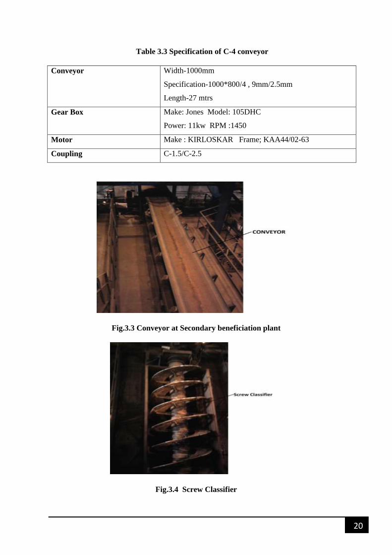
Screw Classifier
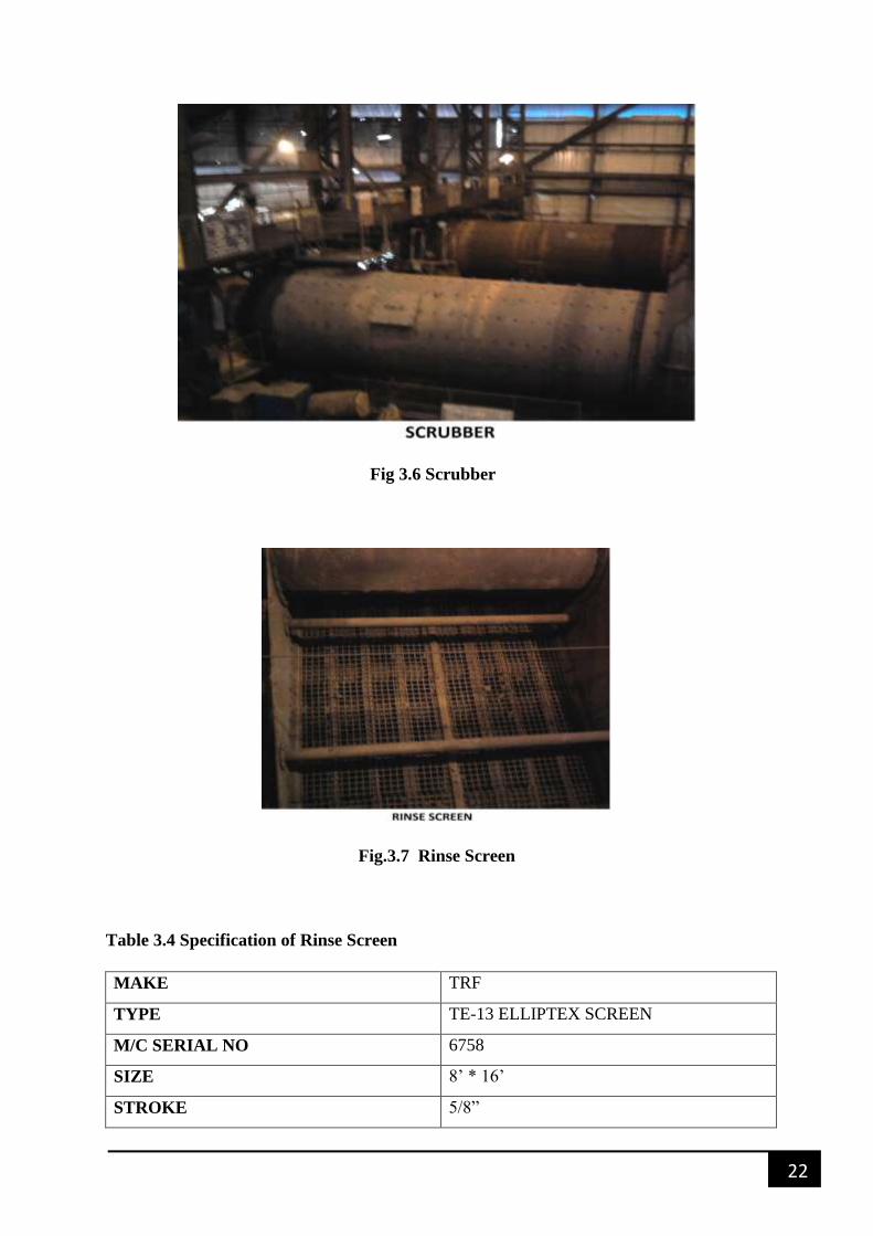
Scrubber
Rinse Screen
Dewatering Screen
Conveyor
20
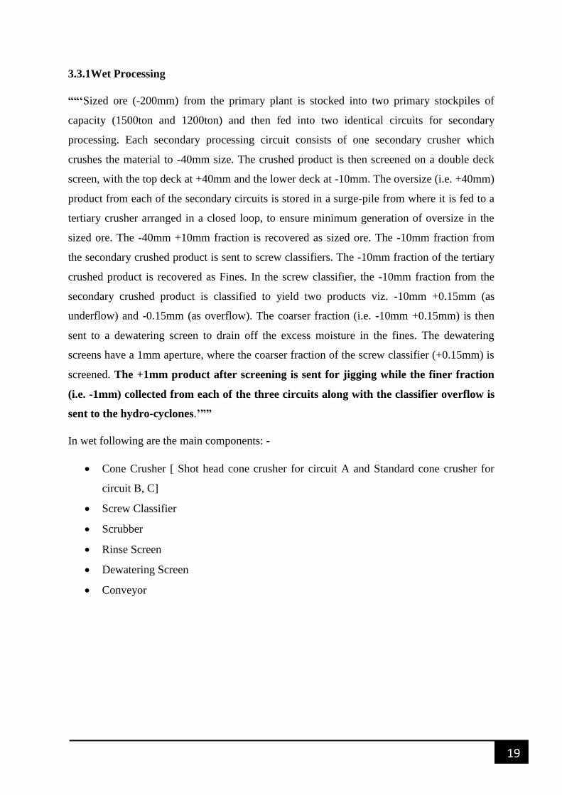
Table 3.3 Specification of C-4 conveyor
Conveyor Width-1000mm
Specification-1000*800/4 , 9mm/2.5mm
Length-27 mtrs
Gear Box Make: Jones Model: 105DHC
Power: 11kw RPM :1450
Motor Make : KIRLOSKAR Frame; KAA44/02-63
Coupling C-1.5/C-2.5
Fig.3.3 Conveyor at Secondary beneficiation plant
Fig.3.4 Screw Classifier
21
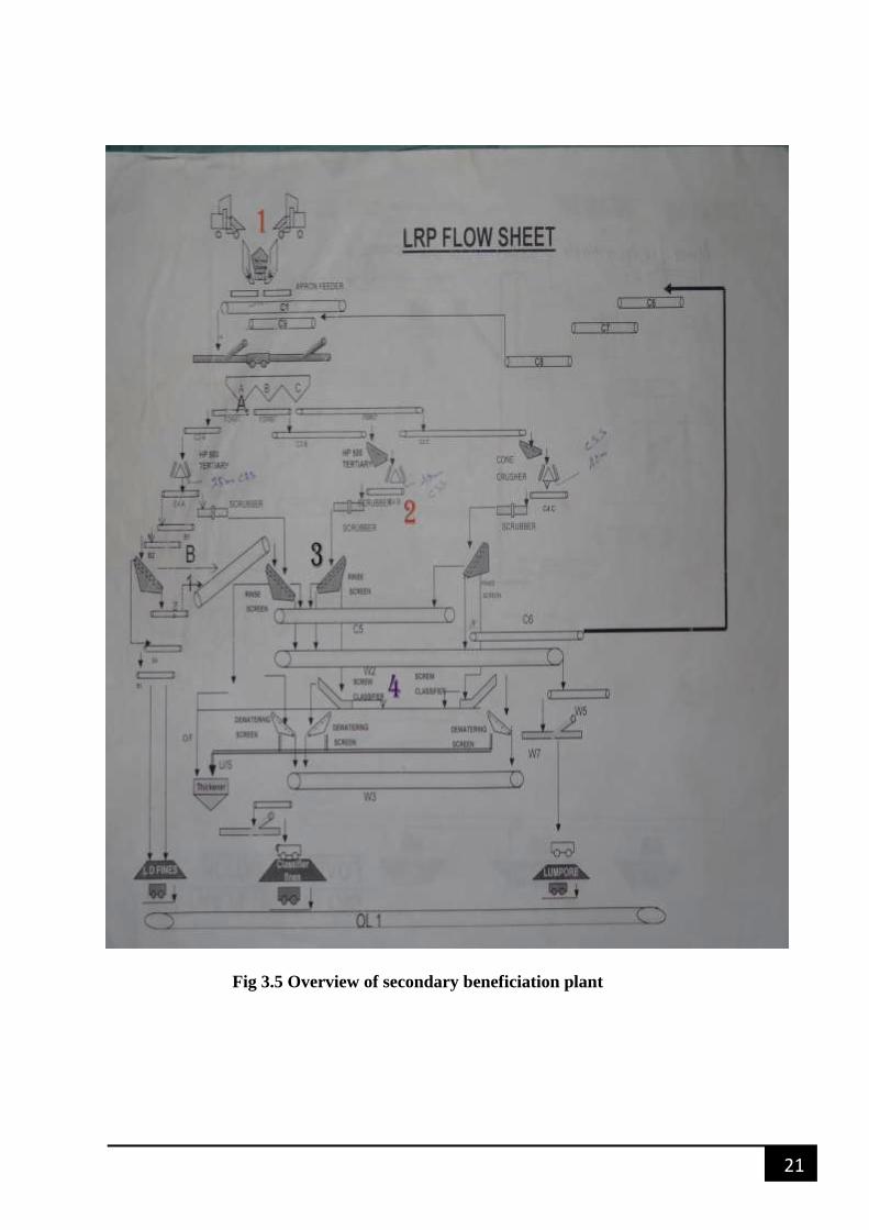
Fig 3.5 Overview of secondary beneficiation plant
22
Fig 3.6 Scrubber
Fig.3.7 Rinse Screen
Table 3.4 Specification of Rinse Screen
MAKE TRF
TYPE TE-13 ELLIPTEX SCREEN
M/C SERIAL NO 6758
SIZE 8’ * 16’
STROKE 5/8‖
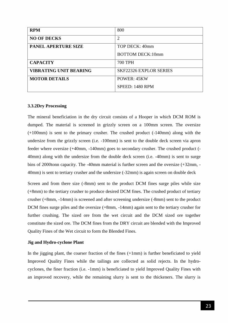
23
RPM 800
NO OF DECKS 2
PANEL APERTURE SIZE TOP DECK: 40mm
BOTTOM DECK:10mm
CAPACITY 700 TPH
VIBRATING UNIT BEARING SKF22326 EXPLOR SERIES
MOTOR DETAILS POWER: 45KW
SPEED: 1480 RPM
3.3.2Dry Processing
The mineral beneficiation in the dry circuit consists of a Hooper in which DCM ROM is
dumped. The material is screened in grizzly screen on a 100mm screen. The oversize
(+100mm) is sent to the primary crusher. The crushed product (-140mm) along with the
undersize from the grizzly screen (i.e. -100mm) is sent to the double deck screen via apron
feeder where oversize (+40mm, -140mm) goes to secondary crusher. The crushed product (-
40mm) along with the undersize from the double deck screen (i.e. -40mm) is sent to surge
bins of 2000tonn capacity. The -40mm material is further screen and the oversize (+32mm, -
40mm) is sent to tertiary crusher and the undersize (-32mm) is again screen on double deck
Screen and from there size (-8mm) sent to the product DCM fines surge piles while size
(+8mm) to the tertiary crusher to produce desired DCM fines. The crushed product of tertiary
crusher (+8mm, -14mm) is screened and after screening undersize (-8mm) sent to the product
DCM fines surge piles and the oversize (+8mm, -14mm) again sent to the tertiary crusher for
further crushing. The sized ore from the wet circuit and the DCM sized ore together
constitute the sized ore. The DCM fines from the DRY circuit are blended with the Improved
Quality Fines of the Wet circuit to form the Blended Fines.
Jig and Hydro-cyclone Plant
In the jigging plant, the coarser fraction of the fines (+1mm) is further beneficiated to yield
Improved Quality Fines while the tailings are collected as solid rejects. In the hydro-
cyclones, the finer fraction (i.e. -1mm) is beneficiated to yield Improved Quality Fines with
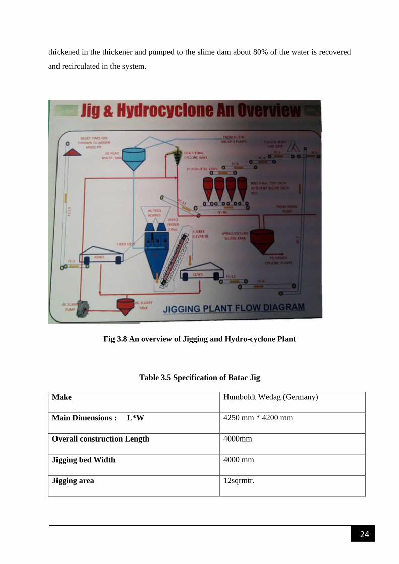
an improved recovery, while the remaining slurry is sent to the thickeners. The slurry is
24
thickened in the thickener and pumped to the slime dam about 80% of the water is recovered
and recirculated in the system.
Fig 3.8 An overview of Jigging and Hydro-cyclone Plant
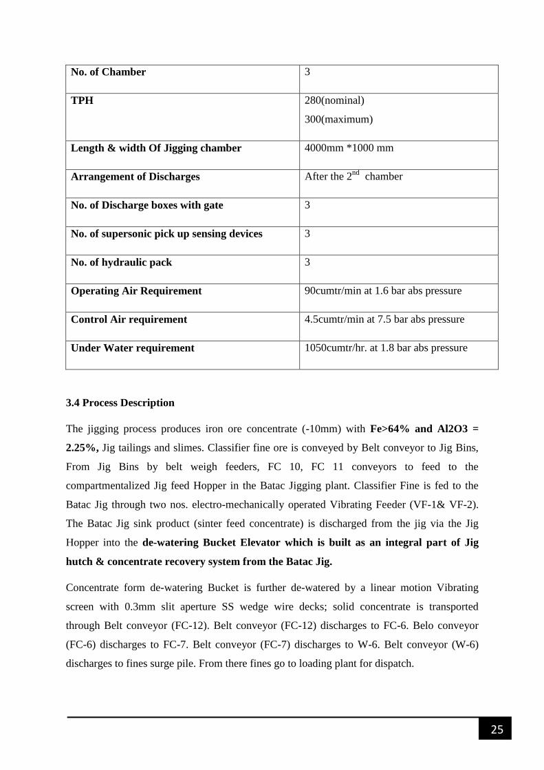
Table 3.5 Specification of Batac Jig
Make Humboldt Wedag (Germany)
Main Dimensions : L*W 4250 mm * 4200 mm
Overall construction Length 4000mm
Jigging bed Width 4000 mm
Jigging area 12sqrmtr.
25
No. of Chamber 3
TPH 280(nominal)
300(maximum)
Length & width Of Jigging chamber 4000mm *1000 mm
Arrangement of Discharges After the 2nd
chamber
No. of Discharge boxes with gate 3
No. of supersonic pick up sensing devices 3
No. of hydraulic pack 3
Operating Air Requirement 90cumtr/min at 1.6 bar abs pressure
Control Air requirement 4.5cumtr/min at 7.5 bar abs pressure
Under Water requirement 1050cumtr/hr. at 1.8 bar abs pressure
3.4 Process Description
The jigging process produces iron ore concentrate (-10mm) with Fe>64% and Al2O3 =
2.25%, Jig tailings and slimes. Classifier fine ore is conveyed by Belt conveyor to Jig Bins,
From Jig Bins by belt weigh feeders, FC 10, FC 11 conveyors to feed to the
compartmentalized Jig feed Hopper in the Batac Jigging plant. Classifier Fine is fed to the
Batac Jig through two nos. electro-mechanically operated Vibrating Feeder (VF-1& VF-2).
The Batac Jig sink product (sinter feed concentrate) is discharged from the jig via the Jig
Hopper into the de-watering Bucket Elevator which is built as an integral part of Jig
hutch & concentrate recovery system from the Batac Jig.
Concentrate form de-watering Bucket is further de-watered by a linear motion Vibrating
screen with 0.3mm slit aperture SS wedge wire decks; solid concentrate is transported
through Belt conveyor (FC-12). Belt conveyor (FC-12) discharges to FC-6. Belo conveyor
(FC-6) discharges to FC-7. Belt conveyor (FC-7) discharges to W-6. Belt conveyor (W-6)
discharges to fines surge pile. From there fines go to loading plant for dispatch.
26
The Batac float product (Rejects/tailings) swims with flowing water out of Batac Jig and
passes through one inclined De-watering fixed sieves before feeding to Vibrating de-watering
screen for final de-watering of rejects and conveyed by a cross belt conveyor (FC-5). Belt
conveyor (FC-5) discharges rejects onto FC-13 for subsequent conveying and disposal of
rejects. Fixed de-watering sieve and vibrating screen is provided with 0.5mm slit aperture SS
wedge wire decks.
Slurried water with fines solid (particle size<0.5mm) from the fixed de-watering sieve and of
vibrating de-watering screen(s) both for rejects and concentrate is collected in a slurry sup.
Centrifugal Slurry pump is pump slurry from the slurry sump of De-gritting cyclone. De-
gritting cyclone recovers the coarser particle from Jig slurry and overflow water of these
cyclones foes to Jig overhead tank for use in the Jig. Under flow of de-gritting cyclone goes
to hydro-cyclone to prevent the coarser particles going to Thickeners. Underflow of hydro-
cyclone goes to slow speed classifier for de-watering then it mix with jig rejects through FC-
14 conveyor.
Jigging air is supplied from Rotary Roots Blower (RRB 1 & 2, 1operating and 1standby)
installed at the Jigging plant. Compressed air for operation of the Batac jig valves, elecro-
pnematically operated cut off valves below Jig head water tank and other requirement within
Batac Jigging plant like purging, flushing etc. is supplied from Screw compressor (SC-1& 2,
1operating and 1standby) and 3000 Ltrs. Capacity Air receiver tank.
Batac Jig underwater is supplied from a Jig water tank installed above the Jigging plant, Re
circulating water from the existing Thickener in requisite quantities and with maximum
permissible solid concentrate is supplied directly to the Jig head water tank through RC
pump#3 or Group 2 pump house, pump as per requirement. A make up water tank also
installed adjacent to the Jig head water tank to supply requisite quantities of make up water
directly to the Jig head water tank to ensure appropriate pressure head for operation of the
Batac Jig, a constant overflow of water from the Jig head water tank back to the existing
Thickeners/Thickener clarified water tank is needed.
JIG: - It is an ore beneficiation machine in which the feed material is stratified according to
its density. It works on gravity separation method
The Batch jig present in Noamundi Iron ore mine stratified High alumina fines Ore to the
alumina concentrate by stratification according to its density by the pulsating motion of
water. It is an air pulsated jig which uses blower air at 0.39 bar pulsation of the jig
27
bed.The thickness of the material layers stratified by specific gravity is sensed with the aid of
a float equipped with a suitable linkage. The system provides a controlled withdrawal of the
heavy fraction over a discharge device. Jigging of great width is equipped with independently
operating discharge devices fitted with separate sensor and hydraulic units. Jig Plant is
mainly composed of following parts: -
Pulse Generators: - Magnitude and kind of kinetic energy, admitted to the
beneficiation process are of decisive importance for successful separation. Therefore,
special attention has should be given to the development of pulse generator for the
controlled admission of compressed air. Disk valves are used for standard and square-
wave, pulsation in BITAC jigs. They are actuated by compressed air.
Rotatory-flap valves: - It is used for standard and square-wave pulsation. They are
actuated by compressed air. The quantities of jigging air are controlled by
electronically both for disk valves and rotary-flap valves. They can be set individually
by means of decade switches. An identical pulsation frequency (40-120
pulsation/min.) is set for all jigging chambers. The specific pulsation of every
chamber is generated from additional time cards. The operating pressure is matched to
the specific operating condition from a PID controller operating on micro-processor
basis. The nominal pressure has been stored in the controller. The operating pressure
can be automatically matched to changed operating conditions be measuring the raw
material feed rate (weigh feeder).
Discharge Devices: - In case of both coarse- and fine grain jigs of great width several
discharge devices have been distributed over the machine width. They operate
independently by their own hydraulic system. The hydraulic units are actuated
indirectly by float sensors.
Coarse-grain discharge device: - Refuse and middling’s are taken to the
discharge shafts over movable jig beds of maximum 3.0m width. Depending
on the quantity of heavy, fraction that has accumulated, the movable jig beds
are opened up to 350 mm. The shaft walls have been protected against wear
by ceramic tiles or wear plates.
28
Fine-grain discharge devices: - The refuse and middling products are
discharged into the bucket elevator over bottom outlets fitted with gates. The
design of these discharge devices focused on aspects of wear and therefore
the bottom outlets are easily replaceable insert boxes made of 15 mm thick
stainless steel. The shafts are 440 mm deep and dew pending on the jig width
their opening measures between 115*1000mm and a maximum of 2000 mm.
The design concept was to keep a size able reserve layer (buffer) inside the
shaft not only to prevent eddying but also to reduce the flow velocity of the
material to be discharged.The lower part of the gate (run-off plate) has been
separated from the gate body and has been rigidly welded to the insert box.
The gate pro (1 er now only consists of the 15mm thick stainless plate which
is moved and guided vertically with the aid of two flats made of stainless
steel). Existing machines can be retrofitted with this modified discharge gate.
Every discharge gate is equipped with its own hydraulic cylinder mounted
vertically above the discharge gate and joined directly to it i.e. without
interposing a shaft. This arrangement results in the following benefits: -
o Extended longevity due to use of stainless steel
o No wear occurring at the jig walls proper
o Reduced machining of mechanical components
o Lubrication of bearings is not necessary because of the absence
of a shaft
o Rapid replacement of gates and insert box
Discharge Control Loop: - The thickness of the material layers stratified by specified
gravity is sensed with the aid of a float equipped with a suitable linkage. Formerly
employed induced current metering units are today replaced by analog displacement
measuring system operating at ultrasonic velocity (2800 m/sec.). The basic float
setting (separating density) is done by additional weights. The layer thickness is
adjusted with a set point potentiometer. The hydraulic system of the discharge gates
are actuated from PID controllers which operate on the basis of microprocessors. The
measurement is made with the float in lowest position. This will preclude false
measurements due to stroke influences. The new system are highlighted by improved
measuring and control accuracy and their insensitive to impact and vibrations.
Discharge control loop:-
29
Chassis
Float
Float guide rod
Guide rolls
Rubber buffer
Indicator dial
Weight disk
Display panel-layer thickness
Adjustable receptacle for displacement sensors
Ultrasonic control bed level
Reflector
Converter
Controller
External set point input
Ultrasonic control is charge opening
Reflector
Hydraulic unit
Discharge shaft
Gate
Overflow weir
Set point layer thickness
Control Cabinet: -
OPERATING INDICATOR FOR AIR CONTROL
LCD display with key board for adjustment of valve control(air in/out).
Operating indication of discharge gates.
LCD display with keyboard for entering various parameters.
LED’s for general status.
Hour meter
Push, buttons with signal lamps for manual operation.
30
DATA ASSIMILATION,
EXPERIMENTATION AND
ANALYSIS
31
4. DATA ASSIMILATION, EXPERIMENTATION AND
ANALYSIS
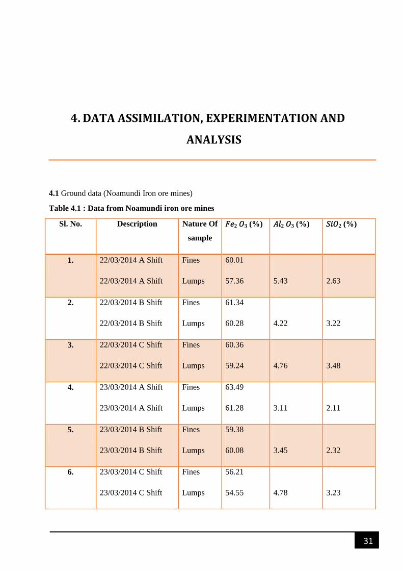
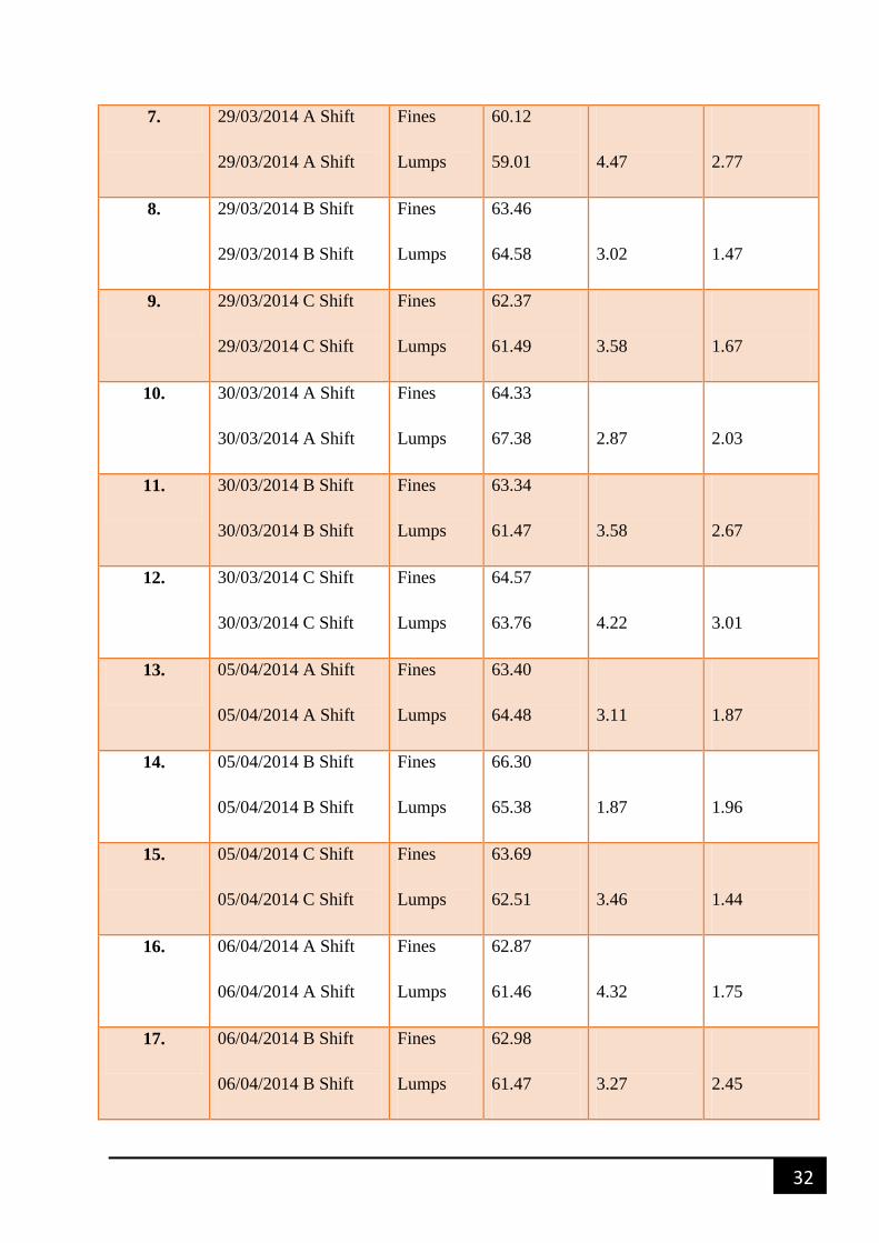
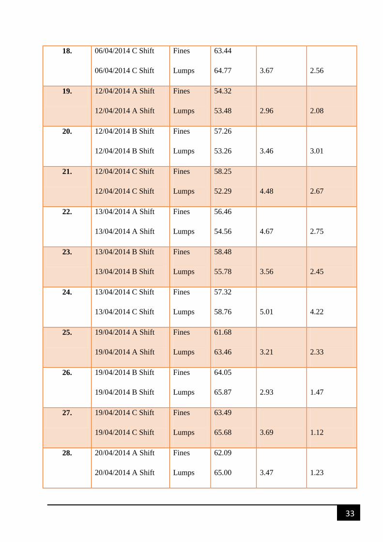
4.1 Ground data (Noamundi Iron ore mines)
Table 4.1 : Data from Noamundi iron ore mines
Sl. No. Description Nature Of
sample
𝐹𝑒2 𝑂3 (%) 𝐴𝑙2 𝑂3 (%) 𝑆𝑖𝑂2 (%)
1. 22/03/2014 A Shift
22/03/2014 A Shift
Fines
Lumps
60.01
57.36
5.43
2.63
2. 22/03/2014 B Shift
22/03/2014 B Shift
Fines
Lumps
61.34
60.28
4.22
3.22
3. 22/03/2014 C Shift
22/03/2014 C Shift
Fines
Lumps
60.36
59.24
4.76
3.48
4. 23/03/2014 A Shift
23/03/2014 A Shift
Fines
Lumps
63.49
61.28
3.11
2.11
5. 23/03/2014 B Shift
23/03/2014 B Shift
Fines
Lumps
59.38
60.08
3.45
2.32
6. 23/03/2014 C Shift
23/03/2014 C Shift
Fines
Lumps
56.21
54.55
4.78
3.23
32
7. 29/03/2014 A Shift
29/03/2014 A Shift
Fines
Lumps
60.12
59.01
4.47
2.77
8. 29/03/2014 B Shift
29/03/2014 B Shift
Fines
Lumps
63.46
64.58
3.02
1.47
9. 29/03/2014 C Shift
29/03/2014 C Shift
Fines
Lumps
62.37
61.49
3.58
1.67
10. 30/03/2014 A Shift
30/03/2014 A Shift
Fines
Lumps
64.33
67.38
2.87
2.03
11. 30/03/2014 B Shift
30/03/2014 B Shift
Fines
Lumps
63.34
61.47
3.58
2.67
12. 30/03/2014 C Shift
30/03/2014 C Shift
Fines
Lumps
64.57
63.76
4.22
3.01
13. 05/04/2014 A Shift
05/04/2014 A Shift
Fines
Lumps
63.40
64.48
3.11
1.87
14. 05/04/2014 B Shift
05/04/2014 B Shift
Fines
Lumps
66.30
65.38
1.87
1.96
15. 05/04/2014 C Shift
05/04/2014 C Shift
Fines
Lumps
63.69
62.51
3.46
1.44
16. 06/04/2014 A Shift
06/04/2014 A Shift
Fines
Lumps
62.87
61.46
4.32
1.75
17. 06/04/2014 B Shift
06/04/2014 B Shift
Fines
Lumps
62.98
61.47
3.27
2.45
33
18. 06/04/2014 C Shift
06/04/2014 C Shift
Fines
Lumps
63.44
64.77
3.67
2.56
19. 12/04/2014 A Shift
12/04/2014 A Shift
Fines
Lumps
54.32
53.48
2.96
2.08
20. 12/04/2014 B Shift
12/04/2014 B Shift
Fines
Lumps
57.26
53.26
3.46
3.01
21. 12/04/2014 C Shift
12/04/2014 C Shift
Fines
Lumps
58.25
52.29
4.48
2.67
22. 13/04/2014 A Shift
13/04/2014 A Shift
Fines
Lumps
56.46
54.56
4.67
2.75
23. 13/04/2014 B Shift
13/04/2014 B Shift
Fines
Lumps
58.48
55.78
3.56
2.45
24. 13/04/2014 C Shift
13/04/2014 C Shift
Fines
Lumps
57.32
58.76
5.01
4.22
25. 19/04/2014 A Shift
19/04/2014 A Shift
Fines
Lumps
61.68
63.46
3.21
2.33
26. 19/04/2014 B Shift
19/04/2014 B Shift
Fines
Lumps
64.05
65.87
2.93
1.47
27. 19/04/2014 C Shift
19/04/2014 C Shift
Fines
Lumps
63.49
65.68
3.69
1.12
28. 20/04/2014 A Shift
20/04/2014 A Shift
Fines
Lumps
62.09
65.00
3.47
1.23
34
29. 20/04/2014 B Shift
20/04/2014 B Shift
Fines
Lumps
61.98
62.24
4.01
3.51
30. 20/04/2014 C Shift
20/04/2014 C Shift
Fines
Lumps
63.11
64.63
3.87
2.34
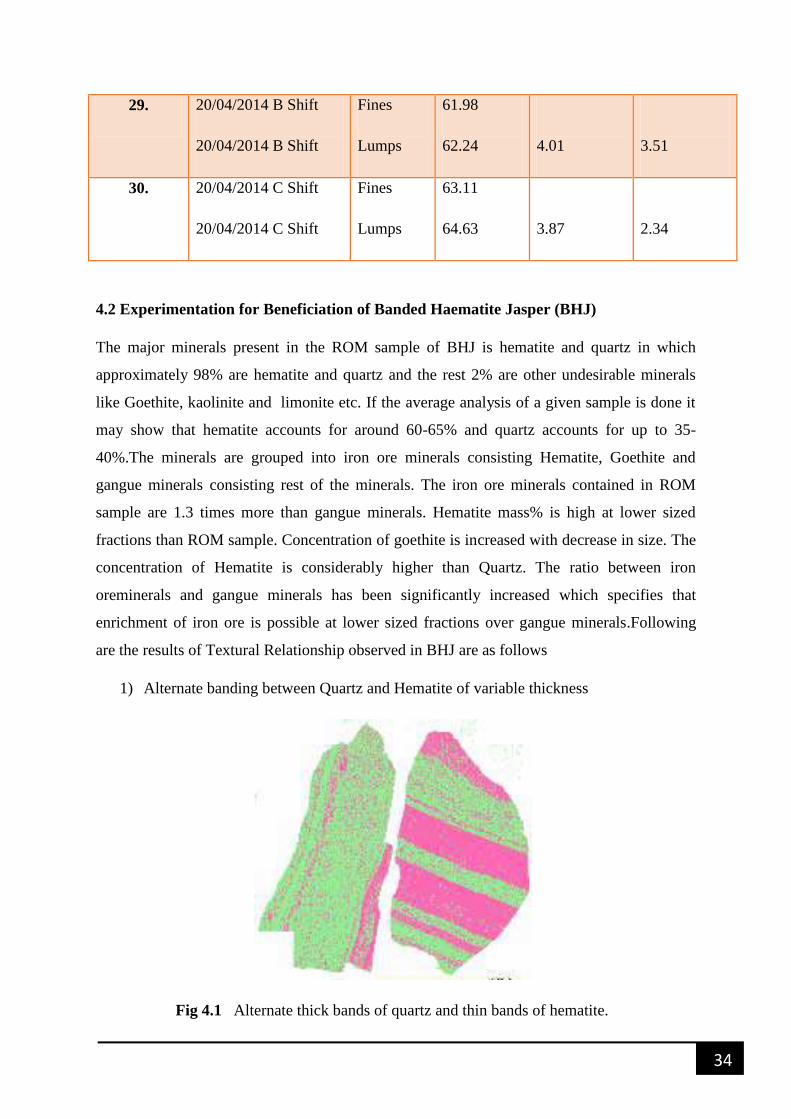
4.2 Experimentation for Beneficiation of Banded Haematite Jasper (BHJ)
The major minerals present in the ROM sample of BHJ is hematite and quartz in which
approximately 98% are hematite and quartz and the rest 2% are other undesirable minerals
like Goethite, kaolinite and limonite etc. If the average analysis of a given sample is done it
may show that hematite accounts for around 60-65% and quartz accounts for up to 35-
40%.The minerals are grouped into iron ore minerals consisting Hematite, Goethite and
gangue minerals consisting rest of the minerals. The iron ore minerals contained in ROM
sample are 1.3 times more than gangue minerals. Hematite mass% is high at lower sized
fractions than ROM sample. Concentration of goethite is increased with decrease in size. The
concentration of Hematite is considerably higher than Quartz. The ratio between iron
oreminerals and gangue minerals has been significantly increased which specifies that
enrichment of iron ore is possible at lower sized fractions over gangue minerals.Following
are the results of Textural Relationship observed in BHJ are as follows
1) Alternate banding between Quartz and Hematite of variable thickness
Fig 4.1 Alternate thick bands of quartz and thin bands of hematite.
35
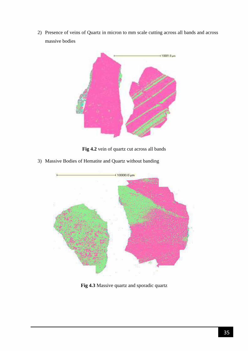
2) Presence of veins of Quartz in micron to mm scale cutting across all bands and across
massive bodies
Fig 4.2 vein of quartz cut across all bands
3) Massive Bodies of Hematite and Quartz without banding
Fig 4.3 Massive quartz and sporadic quartz
36
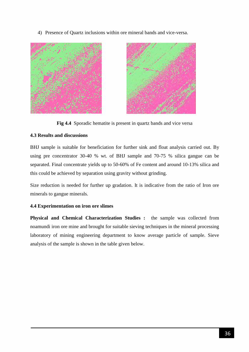
4) Presence of Quartz inclusions within ore mineral bands and vice-versa.
Fig 4.4 Sporadic hematite is present in quartz bands and vice versa
4.3 Results and discussions
BHJ sample is suitable for beneficiation for further sink and float analysis carried out. By
using pre concentrator 30-40 % wt. of BHJ sample and 70-75 % silica gangue can be
separated. Final concentrate yields up to 50-60% of Fe content and around 10-13% silica and
this could be achieved by separation using gravity without grinding.
Size reduction is needed for further up gradation. It is indicative from the ratio of Iron ore
minerals to gangue minerals.
4.4 Experimentation on iron ore slimes
Physical and Chemical Characterization Studies : the sample was collected from
noamundi iron ore mine and brought for suitable sieving techniques in the mineral processing
laboratory of mining engineering department to know average particle of sample. Sieve
analysis of the sample is shown in the table given below.
37
Table 4.2 Sieve Analysis
SIZE FRACTION (SIEVE MESH) CONTENT (%)
-20 2.59
20 -40 3.0
40 -60 2.12
60 -100 3.1
100 -140 3.12
140 -200 3.78
200 -325 4.30
-325 77.91
Table 4.3 Chemical Analysis
𝑭𝒆𝟐𝑶𝟑% 𝑺𝒊𝟐𝑶𝟑% 𝑨𝒍𝟐𝑶𝟑%
62.55 2.35 3.46
Grinding test: for improving the grade of iron ore and for emancipation of iron values from
associated particles, sample was gone through wet grinding test. Experiment was carried out
in mineral processing laboratory, mining department using standard ball mill. Weights of
balls were taken on the basis of bond index. The bond ball mill index test is a measure of the
resistance of the material to crushing and grinding. Before arriving at different options for
beneficiation grinding study is carried out. The objective was to achieve the maximum
liberation of the Iron particles from the associated gangues due to reduction in size. So, the
sample was put for the grinding study to produce samples for further investigations and to
establish grinding parameters. At around 50 % solid consistency in ball mill all grinding
studies were carried out.
38
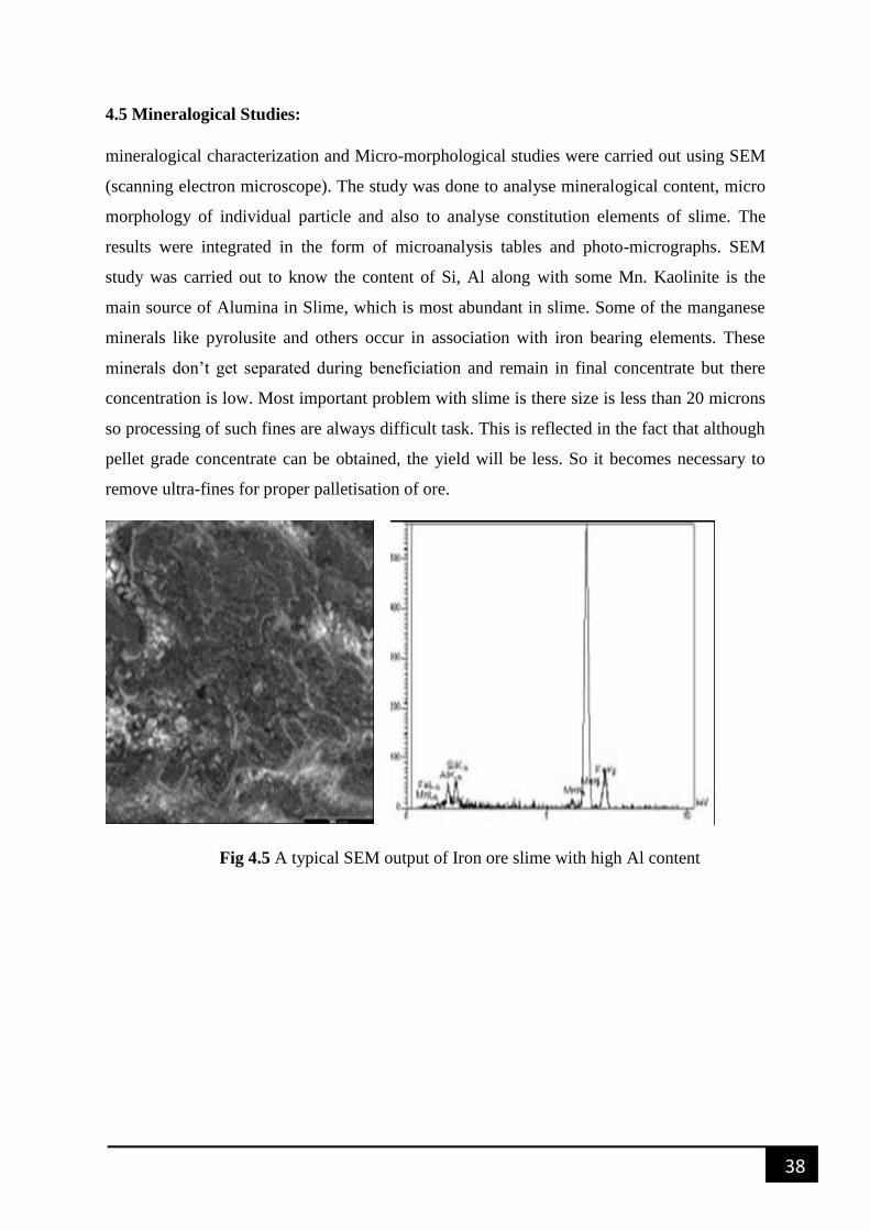
4.5 Mineralogical Studies:
mineralogical characterization and Micro-morphological studies were carried out using SEM
(scanning electron microscope). The study was done to analyse mineralogical content, micro
morphology of individual particle and also to analyse constitution elements of slime. The
results were integrated in the form of microanalysis tables and photo-micrographs. SEM
study was carried out to know the content of Si, Al along with some Mn. Kaolinite is the
main source of Alumina in Slime, which is most abundant in slime. Some of the manganese
minerals like pyrolusite and others occur in association with iron bearing elements. These
minerals don’t get separated during beneficiation and remain in final concentrate but there
concentration is low. Most important problem with slime is there size is less than 20 microns
so processing of such fines are always difficult task. This is reflected in the fact that although
pellet grade concentrate can be obtained, the yield will be less. So it becomes necessary to
remove ultra-fines for proper palletisation of ore.
Fig 4.5 A typical SEM output of Iron ore slime with high Al content
39
4.6 ANALYSIS OF THE DATA ADAPTED FROM DIFFERENT MODES OF
EXPERIMENTATION
1. From the sieve analysis of the slime sample it is clear that 77.91% of the slime is
below 325 microns size
2. Presence of silica, aluminium in gauge sample was found by doing chemical analysis.
3. To liberate iron values from the interlocked gangue elements grinding study was
carried out.
4. To study the extent of interlocking of different elemental constituents of the sample
SEM study was carried out .by this study we know the presence of Al and Si. Al in
the form of Kaolinite is the most abundant among the other constituents Manganese
minerals such as Pyrolusite etc occur in association with iron bearing minerals. They
generally don’t get separated during processing and remain in the final concentrate.
However, their yields are very low.
5. Through above studies it is clearly indicated that presence of Al and Si are there, so it
need to be removed using proper beneficiation process.
40
SUMMARY AND CONCLUSION
CHAPTER-5
41
5. SUMMARY AND CONCLUSION
By looking at results indicated by characterization of the BHJ sample tests may be done using
2 Fundamental principles of separation namely:
Magnetic separation
Gravity Separation
Floatex gravity slime table is used for garavity separation and Wet high Intensity magnetic
separator (WHIMS )is used for carrying out magnetic separation.
Drawback in using WHIMS technology is that the grains of jasper may concentrate at high
intensities of gauss. Due to this problem separation by gravity using gravity spirals seems a
more feasible and better option. Prior to gravity separation the sample may have to be
subjected to pre concentration using wash waterless spirals. Different feed rates, pulp
densities and splitter positions are used for conducting tests.
Iron ore slimes
The occurrence of Kaolinite causes high alumina content in the slime. Advancement in the
field of beneficiation methods based on the principle of froth floatation/selective dispersion
gravity separation, magnetic separation, and bio beneficiation can be used for the up
gradation of iron ore slimes in India. The enhanced low alumina ore can then be used in the
main stream industry for sintering and pelletization.
The waste management can be carried out using suitable techniques like, thermal conversion
to iron and glass ceramics semi dry disposal, iron rich cements. Certain test need to be carried
out to validate the effectiveness of the above techniques. Based on the results of the tests a
suitable flow chart can be developed for the beneficiation of slime. The tests comprise
floatation and WHIMS (Wet high intensity magnetic separator), hydrocyclone, spiral.
Hydrocyclone
For the upgradation of Iron values as well as for de-sliming of slime particles present in the
sample Hydrocyclone can be used. Samples contain large amount of slime materials
Containing of particles falling in the sub micron size category, de-sliming has to be carried
42
out prior to flotation. The underflow and overflow constituents of the cyclone have to be
collected at a steady state for a fixed time, dried, weighed and analysed for the desired Iron
and other constituents. Further analysis of overflow & underflow samples collected at finest
operating conditions should be done.
Spiral
To enrich the Iron content of the classified sample (hydrocyclone underflow) a spiral
concentrator of 100 mm diameter can be used. Advantage of using spiral is that it is an
energy saving gravity equipment where large quantities of sample can be served for pre
concentrations. Iron ore sample has to be fed to the centrifugal pump at the requisite solids
consistency and the slurry has to be kept re-circulating for a predetermined time in the spiral
study. Complete concentrate and tailings are then to be collected after attaining the steady
state. All the products thus achieved were dried, weighed and examined.
Wet High Intensity Magnetic Separation
The high gradient magnetic separator (HGMS) and wet high intensity magnetic separator
(WHIMS) has to be used at various magnetic field intensities to recuperate the fine Iron
values from the hydrocyclone over flow or spiral tailings. Different magnetic groves of
width and matrix with movable currents to provide different magnetic intensities are
provisions of both the separators .A desired concentration of solids has to be passed through
the magnetic separator after this. Many a times the magnetic products have to be cleaned in
second stage to enhance the superiority of the product from first stage separation.
Flotation
To select either direct or reverse flotation method to optimize reagent mixture and to generate
the number of stages in the operations, batch flotation studies have to be carried out.
Subaeration flotation machine needs to be used for the batch flotation studies Suitable
frothing agent and Cationic and anionic reagents have to be used as collectors. To get good
grade concentrate with high recoveries flotation condition needs to be optimised.
After this column flotation studies have to be carried out by using glass column of
appropriate diameter. At nominal capacity of 15kg approximately of Iron ore fines per hour
with the help of a peristaltic pump the column has to be operated. After attaining the steady
state and analysed for Iron content both the concentrate and tailings are then to be collected
separately.
43
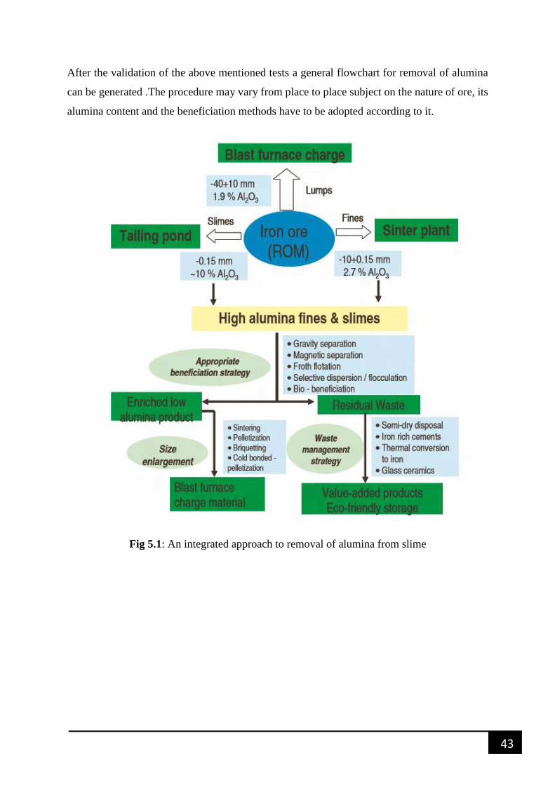
After the validation of the above mentioned tests a general flowchart for removal of alumina
can be generated .The procedure may vary from place to place subject on the nature of ore, its
alumina content and the beneficiation methods have to be adopted according to it.
Fig 5.1: An integrated approach to removal of alumina from slime
44
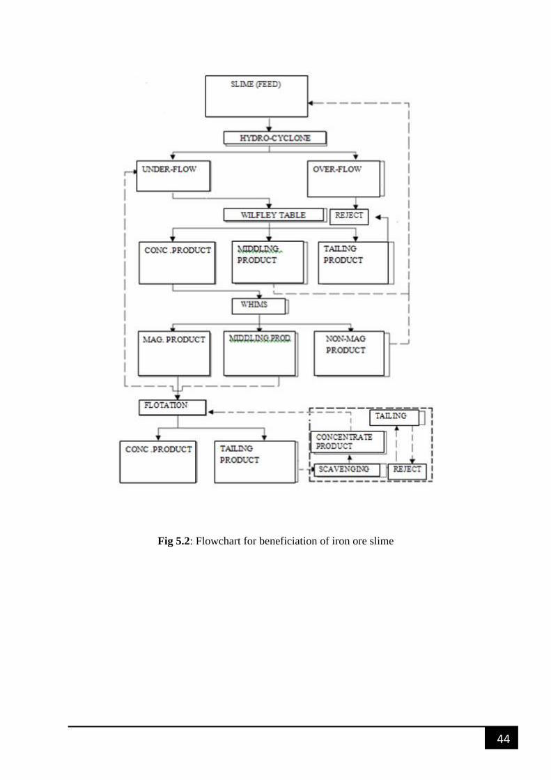
Fig 5.2: Flowchart for beneficiation of iron ore slime
45
REFERENCES
CHAPTER-6
46
6. REFERENCES
1. Pal B.K and Nayak N.P, ―Feasibility of Beneficiation of Low Grade Iron Ore Fines/
Slimes‖,pp 2- 4
2. Nayak N.P and Pal B.K, ―Characterization driven processing of Indian Iron ore Slime‖,pp
1-9
3. Prasad, N., Ponomarev, M.A., Mukherjee, S.K., Sengupta, P.K., Roy, P.K., and
Gupta, S.K. (1988) Introduction of new technologies for beneficiation of Indian
hematite ores, reduction of losses and increase in their quality. In XVI International
Mineral Processing Congress; Forssberg, E. (ed.); 1369–1380.
4. Das, B., Prakash, S., Mohapatra, B.K., Bhaumik, S.K., and Narasimhan, K.S.
(1992) Beneficiation of iron ore slimes using hydrocyclone. Mineral and Metallurgical
Processing, 9 (2): 101–103.
5. Brief Final report on characterization of Banded Hematite Jasper.
6. Minutes of 43rd meeting of the central geological programming board on 29.09.2008,
Ministry of Mines, New Delhi.
7. Misra, B.K. et al., 2007, In: International Seminar on Iron ore Beneficiation Pelletization,
Ministry of Steel, New Delhi.
8. Mukhopadhyay, A. and Chanda, S K., 1972, Sedimentary Geology, 8, p. 113
9. Mukherjee, A.K. and Mishra, B.K., 2006, Mineral Engineering, vol 19, 9, pp.952.
10. Mukherjee, A.K. and Mishra, B.K. 2006, Int. Journal of Mineral Processing vol.81, 3,
pp.187.
11. Mishra, B.K. and Adhikari, B. 1999, Mineral Engineering. vol. 12, 12, pp.1469.
12. http://www.hematiteironore.com/
13. http://www.magnetiteironore.com/
14. Pradip, ―Processing of Alumina-Rich Indian Iron Ore Slimes,‖ International Journal of
Mineral, Metals and Materials Engineering, Vol. 59, No. 5, 2006, pp. 551- 568.
15. A. Bandopadhyay, ―Multi-Gravity Separator—Equipment for Separation of Fines,‖
Processing of Fines, Vol. 2, 2000, pp. 81-92.


![Beneficiation of phosphate ore [s. k. kawatra]](https://img.pdfslide.us/doc/110x75/58a73da51a28ab84308b6175/beneficiation-of-phosphate-ore-s-k-kawatra.jpg)