Embed Size (px)
Citation preview

Bending plate analysis in ABAQUS package
Tomasz Żebro, Jerzy Pamin
Version 1.1, 2017-05-18

2
1. Problem definition
The task is to solve the statics of a slab (plate in bending).The geometry of the plate, its thickness, boundary
conditions and loading are defined in the figure below. Decide about the set of physical units you use – here
data will be input in Newtons and meters.
2. Modelling in ABAQUS package
The tutorial is written assuming the user has made first steps in ABAQUS modelling and solved the
problem of statics of a panel (plane stress two-dimensional case). Whenever a step of model generation
procedure is similar to the case of a panel the Reader is referred to the introductory tutorial.
Abbreviation used: (SC) – single-click of left mouse button, (DC) – double-click of left mouse button.
Remark: the input can be specified following the Model Tree on the left or alternatively selecting a sequence of
Modules and picking icons in the center.
q=-10kN/m2
6m
3m
Young’s modulus: E=30GPa Poisson’s ratio: ν=0.16 Plate thickness: h=0.20m Uniform pressure: q=-10kN/m2

3
Basic data Model Tree/(DC)Parts Set: 3D space, Deformable body, Base Feature: Shell, Type: Planar, Approximate size 20. (SC) Continue
Slab geometry In the sketcher pick the segment line and generate a rectangular domain 6mx3m.
Material definition Model Tree /(DK)Materials Define isotropic elastic material with E=30E9, ν=0.16. (SC) OK

4
Section definition Model Tree/(DK)Sections Define section (thickness) by setting: Shell, Homogenous, (SC)Continue, input thickness 0.20 as shown in the figure. (SC)OK Next associate the material properties to the model part via section assignment: Model Tree/Parts/Part-1/Section Assignments (SC)OK
Instance generation Model Tree/(DK)Assembly Instances Accept the default options to create a modelling instance for the analyzed part.
Loaded surface Model Tree/Assembly/ (DK)Surfaces Select the plate surface to be loaded: (SC)Continue, click in the rectangular domain and confirm (SC) Done, pick the purple surface.
5
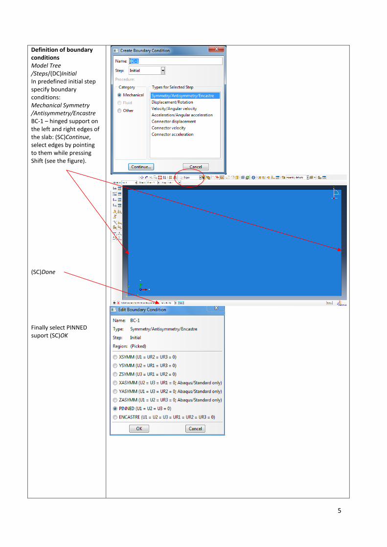
Definition of boundary conditions Model Tree /Steps/(DC)Initial In predefined initial step specify boundary conditions: Mechanical Symmetry /Antisymmetry/Encastre BC-1 – hinged support on the left and right edges of the slab: (SC)Continue, select edges by pointing to them while pressing Shift (see the figure). (SC)Done Finally select PINNED suport (SC)OK

6
(DC)Initial Next specify boundary conditions for the clamped edge: BC-2 – (DC)Continue, indicate the upper edge. (SC)Done And select ENCASTRE support type (SC)OK
Specification of loading Model Tree /(DC)Steps Generate new step called Step-1 and specify mechanical load – (SC)Pressure applied in this step (it is positive when it is directed towards the surface) (SC)Continue

7
Click inside the rectangular domain and select the surface Purple to which pressure should be applied. Input the pressure value (with a proper sign).
Mesh generation From top bar select menu Mesh Controls. Set element shape and meshing method. Next select finite elements type from menu Mesh/Element Type as shown in the figure. Select menu Seeds and in Global Seeds set the element size 0.3 (SC)OK

8
Starting computations Model Tree/Jobs generate a new task (job). Click Data Check, then Submit and when the job has been computed click Monitor.
Postprocessing Set the options of result presentation so that extreme values and their locations for selected quantities are shown. Analyze stress contour plots (isoline graphs) for Mises stress, stresses in the two model directions, deflections (displacements Uz) and nodal reaction forces RF3. Stresses can be monitored at the top or bottom surface of the slab. The surface can be selected in the dialog box Field Output by clicking Section Points.

9