Embed Size (px)
Citation preview
REPORT
BENCHMARKING THE CONSTRUCTABILITY OF THE MIT ROOF SYSTEM ON IBACOS LAB HOME B
PITTSBURGH, PA
ENERGY EFFICIENT INDUSTRIALIZED HOUSING (EEIH) RESEARCH PROGRAM
(The EEIH project is jointly conducted by the Center for Housing Innovation
at the University of Oregon, the Florida Solar Energy Center and the Department of Industrial Engineering and Management Systems at the
University of Central Florida.)
Sponsored by: United States Department of Energy
Contract No. DE-FC03-89SF17960
May 1995
Prepared by: Michael A. Mullens
Tom Gawlik Mag Malek
UNIVERSITY OF CENTRAL FLORIDA
DEPARTMENT OF INDUSTRIAL ENGINEERING AND MANAGEMENT SYSTEMS
PO BOX 163630, ORLANDO, FL 32816-3630 TEL. (407) 823-5703
EXECUTIVE SUMMARY
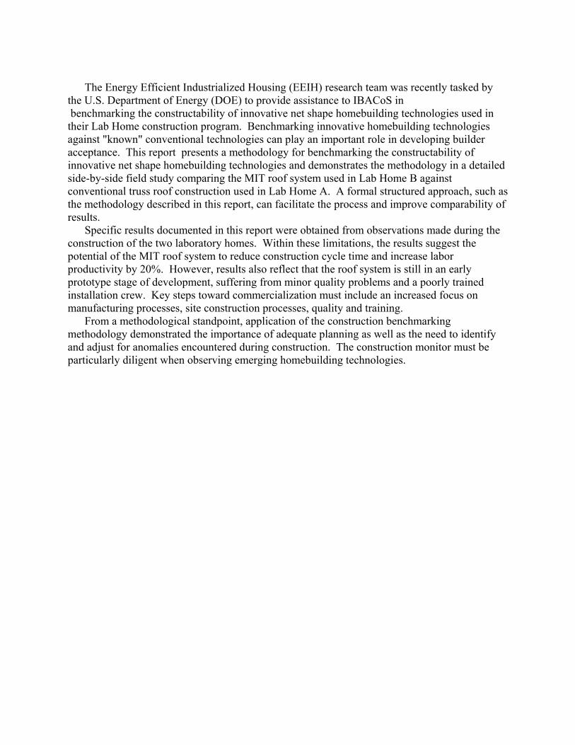
The Energy Efficient Industrialized Housing (EEIH) research team was recently tasked by
the U.S. Department of Energy (DOE) to provide assistance to IBACoS in benchmarking the constructability of innovative net shape homebuilding technologies used in their Lab Home construction program. Benchmarking innovative homebuilding technologies against "known" conventional technologies can play an important role in developing builder acceptance. This report presents a methodology for benchmarking the constructability of innovative net shape homebuilding technologies and demonstrates the methodology in a detailed side-by-side field study comparing the MIT roof system used in Lab Home B against conventional truss roof construction used in Lab Home A. A formal structured approach, such as the methodology described in this report, can facilitate the process and improve comparability of results.
Specific results documented in this report were obtained from observations made during the construction of the two laboratory homes. Within these limitations, the results suggest the potential of the MIT roof system to reduce construction cycle time and increase labor productivity by 20%. However, results also reflect that the roof system is still in an early prototype stage of development, suffering from minor quality problems and a poorly trained installation crew. Key steps toward commercialization must include an increased focus on manufacturing processes, site construction processes, quality and training.
From a methodological standpoint, application of the construction benchmarking methodology demonstrated the importance of adequate planning as well as the need to identify and adjust for anomalies encountered during construction. The construction monitor must be particularly diligent when observing emerging homebuilding technologies.
1
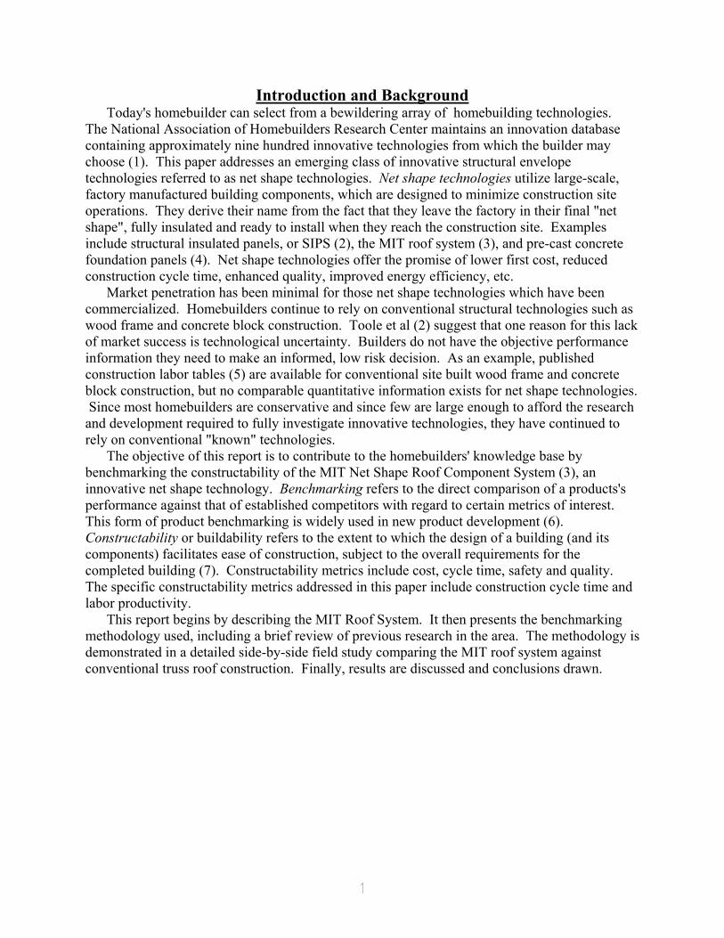
Introduction and Background Today's homebuilder can select from a bewildering array of homebuilding technologies.
The National Association of Homebuilders Research Center maintains an innovation database containing approximately nine hundred innovative technologies from which the builder may choose (1). This paper addresses an emerging class of innovative structural envelope technologies referred to as net shape technologies. Net shape technologies utilize large-scale, factory manufactured building components, which are designed to minimize construction site operations. They derive their name from the fact that they leave the factory in their final "net shape", fully insulated and ready to install when they reach the construction site. Examples include structural insulated panels, or SIPS (2), the MIT roof system (3), and pre-cast concrete foundation panels (4). Net shape technologies offer the promise of lower first cost, reduced construction cycle time, enhanced quality, improved energy efficiency, etc.
Market penetration has been minimal for those net shape technologies which have been commercialized. Homebuilders continue to rely on conventional structural technologies such as wood frame and concrete block construction. Toole et al (2) suggest that one reason for this lack of market success is technological uncertainty. Builders do not have the objective performance information they need to make an informed, low risk decision. As an example, published construction labor tables (5) are available for conventional site built wood frame and concrete block construction, but no comparable quantitative information exists for net shape technologies. Since most homebuilders are conservative and since few are large enough to afford the research and development required to fully investigate innovative technologies, they have continued to rely on conventional "known" technologies.
The objective of this report is to contribute to the homebuilders' knowledge base by benchmarking the constructability of the MIT Net Shape Roof Component System (3), an innovative net shape technology. Benchmarking refers to the direct comparison of a products's performance against that of established competitors with regard to certain metrics of interest. This form of product benchmarking is widely used in new product development (6). Constructability or buildability refers to the extent to which the design of a building (and its components) facilitates ease of construction, subject to the overall requirements for the completed building (7). Constructability metrics include cost, cycle time, safety and quality. The specific constructability metrics addressed in this paper include construction cycle time and labor productivity.
This report begins by describing the MIT Roof System. It then presents the benchmarking methodology used, including a brief review of previous research in the area. The methodology is demonstrated in a detailed side-by-side field study comparing the MIT roof system against conventional truss roof construction. Finally, results are discussed and conclusions drawn.
2
MIT Roof System The MIT Net Shape Roof Component System (3) is a factory-built roof system designed as
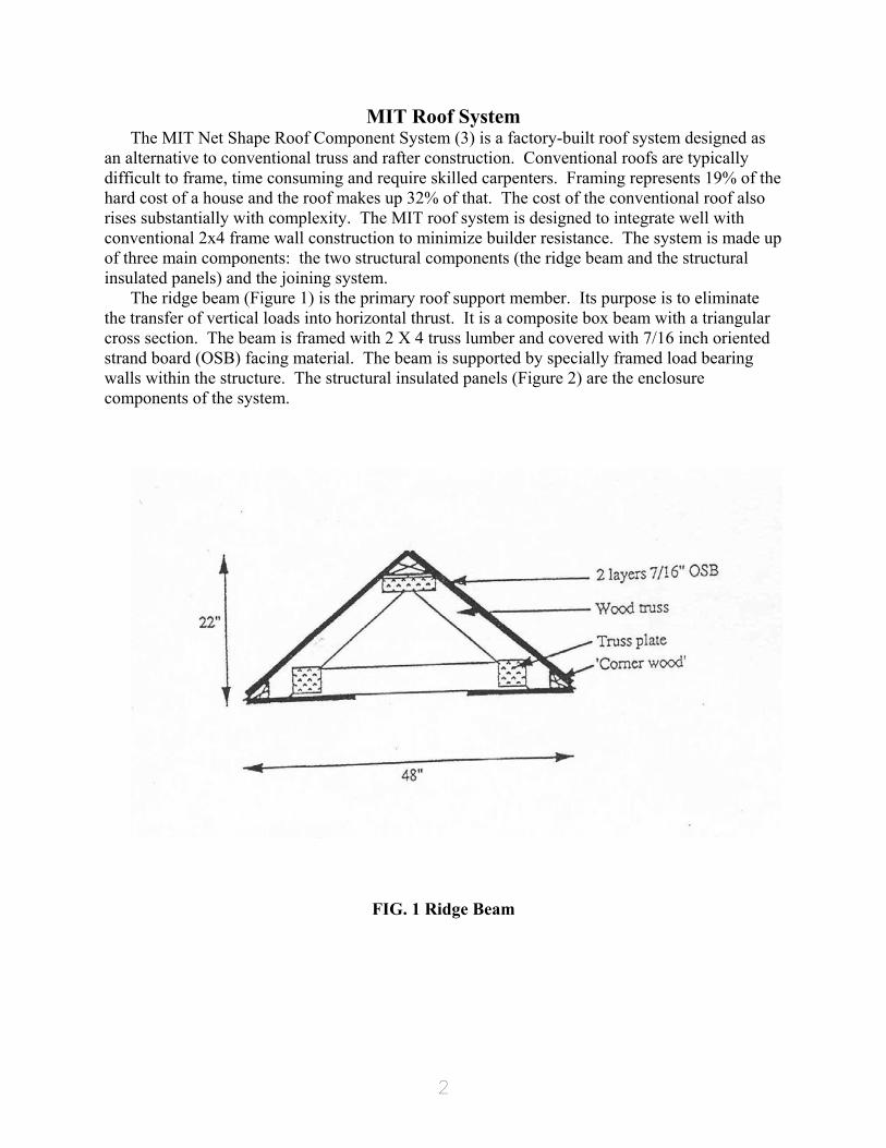
an alternative to conventional truss and rafter construction. Conventional roofs are typically difficult to frame, time consuming and require skilled carpenters. Framing represents 19% of the hard cost of a house and the roof makes up 32% of that. The cost of the conventional roof also rises substantially with complexity. The MIT roof system is designed to integrate well with conventional 2x4 frame wall construction to minimize builder resistance. The system is made up of three main components: the two structural components (the ridge beam and the structural insulated panels) and the joining system.
The ridge beam (Figure 1) is the primary roof support member. Its purpose is to eliminate the transfer of vertical loads into horizontal thrust. It is a composite box beam with a triangular cross section. The beam is framed with 2 X 4 truss lumber and covered with 7/16 inch oriented strand board (OSB) facing material. The beam is supported by specially framed load bearing walls within the structure. The structural insulated panels (Figure 2) are the enclosure components of the system.
FIG. 1 Ridge Beam
3
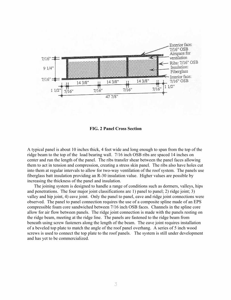
FIG. 2 Panel Cross Section
A typical panel is about 10 inches thick, 4 feet wide and long enough to span from the top of the ridge beam to the top of the load bearing wall. 7/16 inch OSB ribs are spaced 14 inches on center and run the length of the panel. The ribs transfer shear between the panel faces allowing them to act in tension and compression, creating a stress skin panel. The ribs also have holes cut into them at regular intervals to allow for two-way ventilation of the roof system. The panels use fiberglass batt insulation providing an R-30 insulation value. Higher values are possible by increasing the thickness of the panel and insulation.
The joining system is designed to handle a range of conditions such as dormers, valleys, hips and penetrations. The four major joint classifications are 1) panel to panel; 2) ridge joint; 3) valley and hip joint, 4) eave joint. Only the panel to panel, eave and ridge joint connections were observed. The panel to panel connection requires the use of a composite spline made of an EPS compressible foam core sandwiched between 7/16 inch OSB faces. Channels in the spline core allow for air flow between panels. The ridge joint connection is made with the panels resting on the ridge beam, meeting at the ridge line. The panels are fastened to the ridge beam from beneath using screw fasteners along the length of the beam. The eave joint requires installation of a beveled top plate to match the angle of the roof panel overhang. A series of 5 inch wood screws is used to connect the top plate to the roof panels. The system is still under development and has yet to be commercialized.
4
Benchmarking Methodology Previous research has confirmed the importance of evaluating innovative construction
technologies against their conventional counterparts. Multi-criteria evaluation methodologies have been suggested, including the Analytic Hierarchy Process (8), simple weighting methods (9), and a Building Technology Identification and Evaluation system (10). Primary metrics which have been proposed include: structural serviceability, fire safety, habitability, durability, constructability, maintainability, architectural function, first cost, energy efficiency, etc. The U.S. Department of Energy (DOE) uses a multi-criteria analysis referred to as technology characterization (TC) to "provide a solid foundation of consistent and credible information on the current status of the technical performance, cost and environmental characteristics of new technologies being considered by DOE." A TC was recently prepared comparing the performance of structural insulated panels (SIPs) against conventional stick-built 2x4 wood frame construction (11).
The multi-criteria methodologies described above require detailed performance measurements or estimates for each of the technologies being evaluated. Friedman (12) compared the cost (price), production time and quality of homes built using conventional (stick built) and prefabricated (modular, panelized and pre-cut) construction. His methodology utilized quotes from builders/manufacturers for comparable architectural house designs. He concluded that conventional construction was less expensive than prefabricated construction, but it took longer to build. Smith, Grobler and Miller (13) compared framing labor productivity between traditional (stick built) and systems (modular) home construction. The methodology utilized video-taped field study results which were analyzed to estimate elemental production process times. Their findings suggested that, ideally, systems framing labor should be significantly less than that for traditional framing methods; however, in practice, the savings were not significant. Armacost, Mullens and Swart (14) developed a framework for benchmarking the construction cost of innovative homebuilding technologies. The methodology formalized and extended Smith et al's approach, utilizing a formal cost model and broadening the analysis to include other construction cost items including materials, capital and indirect operating costs. The methodology was demonstrated by benchmarking the construction costs of walls built using prefabricated components (frame panels and SIPs) against similar stick built walls. The results suggested that panelized construction and stick built construction had comparable construction costs, but SIP construction was more expensive. Laquatra et al (15) compared panel manufacturing costs for an innovative Optimum Value Engineered long-wall panel against a more typical short wood frame panel. The methodology used was not described in the paper. It should be noted that all studies were based on very small sample sizes and results cannot be generalized. In a related area, Eldin and Egger (16) described the role of a camcorder in improving construction productivity.
The two research efforts (13,14), which fully described their benchmarking methodologies, suggested that there were difficulties benchmarking innovative homebuilding technologies. First, the house is a very large scale system. The cost and time required to collect and analyze field data can be substantial and has contributed to the lack of data. Second, observed construction site operations are not always comparable. It is difficult to find the same architectural design constructed using the desired conventional and innovative technologies. Emerging technologies are likely to be ill-defined and highly variable. This can make comparisons difficult, particularly with respect to highly refined conventional technologies. Problems which were repeatedly observed in field studies included: quality problems from the
5
factory, ill-defined and poorly engineered assembly methods, and poorly trained and unmotivated crews. The methodology described next addresses these issues.
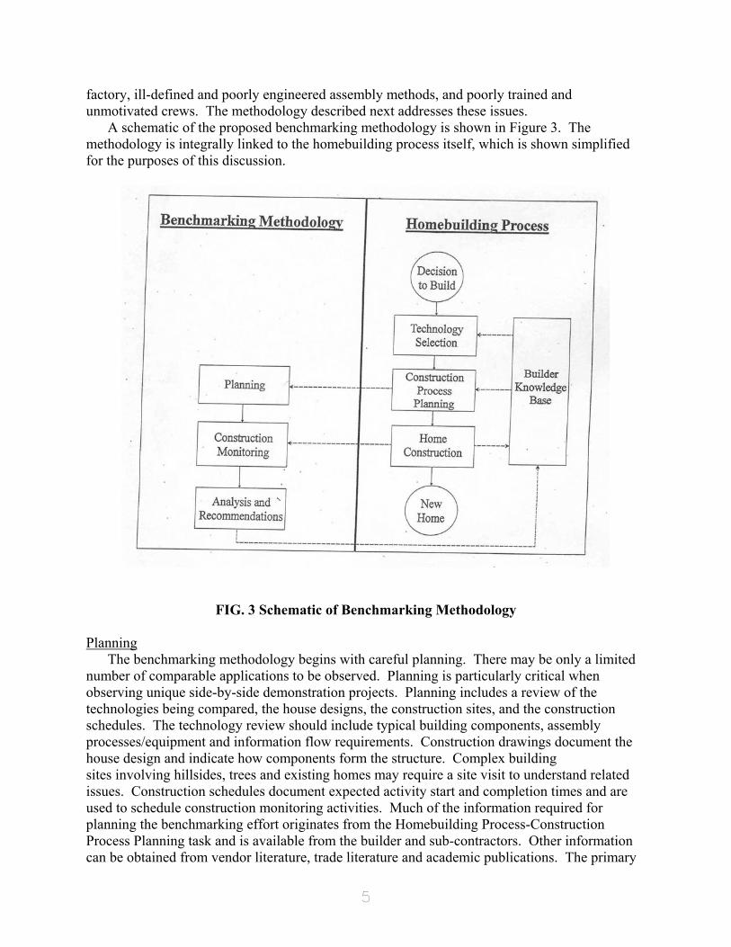
A schematic of the proposed benchmarking methodology is shown in Figure 3. The methodology is integrally linked to the homebuilding process itself, which is shown simplified for the purposes of this discussion.
FIG. 3 Schematic of Benchmarking Methodology Planning
The benchmarking methodology begins with careful planning. There may be only a limited number of comparable applications to be observed. Planning is particularly critical when observing unique side-by-side demonstration projects. Planning includes a review of the technologies being compared, the house designs, the construction sites, and the construction schedules. The technology review should include typical building components, assembly processes/equipment and information flow requirements. Construction drawings document the house design and indicate how components form the structure. Complex building sites involving hillsides, trees and existing homes may require a site visit to understand related issues. Construction schedules document expected activity start and completion times and are used to schedule construction monitoring activities. Much of the information required for planning the benchmarking effort originates from the Homebuilding Process-Construction Process Planning task and is available from the builder and sub-contractors. Other information can be obtained from vendor literature, trade literature and academic publications. The primary
6
product of the planning task is a construction monitoring plan which specifies when monitoring will occur, how construction activities will be documented, how many monitors are required, video camera requirements and optimum locations for observation. Construction Monitoring
Construction monitoring is the process of observing and documenting relevant operations on the construction site. Methods of data collection include: personal observation, conversations with laborers and supervision, video taping and work sampling. A combination of the above methods is normally used because one data source is seldom sufficient to fully document construction activities.
Video tape recording of the construction process is useful to facilitate post-construction analysis. Additional features which can add value to this process include: 1) utilizing a video camera with the date and time superimposed on the recording; and 2) narrating the recording, focussing on issues which might otherwise be missed. Several issues should be noted regarding the use of video cameras: 1) multiple monitors with cameras may be required to document parallel construction processes; 2) highly redundant activities (e.g., laying concrete blocks) need not be continuously taped; and 3) there may be an opportunity to use the video recordings as a productivity enhancement tool on the construction site, by reviewing selected segments with laborers and supervision (16). These issues should be resolved in the planning stage.
All construction monitors are instructed to maintain written documentation of: 1) key activities, their start and completion times, and their manpower requirement; 2) deviations from standard practice and their cause (weather, defects from factory, assembly difficulties, problems with interfacing systems, crew training, material shortages, delivery delays, inspection delays, supervision problems, etc.); and 3) pace of the work crew. Analysis and Recommendations
The analysis of data collected during construction monitoring includes the following steps: 1) Using video and supporting data, construct a Gantt Chart indicating each construction
activity, activity start and finish time, the duration of the activity and the number of laborers used. The Gantt Chart should use a scale denoting continuous working hours, uninterrupted by breaks, lunch or end of day.
2) Calculate the actual construction cycle time (Eq.1) using data from the Gantt Chart. Cycle time is defined to be the clock time between the start and finish of the building system under study. It measures the speed in which the system can be installed. Estimates are expressed in continuous working hours.
TOTCYCLE = TFINLast - TSTARTFirst (1) where:
TOTCYCLE ¡� total construction cycle time TFINi � finish time of ith activity TSTARTi � start time of ith activity
3) Calculate actual labor content (Eq. 2) using data developed on the Gantt Chart. Labor content is defined as the total man-hours required by the crew over the course of the construction cycle.
TOTLAB = (TFINi - TSTARTi) MPi (2) where:
TOTLAB � total labor content MPi � # of laborers for ith activity
∑n
7
n � number of activities observed 4) Estimates developed in Steps 1-3 reflect actual construction operations and may
include significant deviations from standard practice. Normalized estimates are developed to minimize the impact of these deviations and maximize comparability. They are obtained by reconfiguring the Gantt Chart to reflect the following changes: 1) all non-standard activities caused by problems are eliminated (e.g., trimming oversize manufactured components to fit); 2) activities requiring excessive cycle times or laborers due to problems are adjusted (e.g., if the oversize manufactured component must be force-fit); and 3) crew work pace is equalized to 100% (the pace that a typical laborer can maintain for an eight hour workday without excessive physical stress). It should be noted that adjustments to the Gantt Chart should not be made for problems endemic to the technology (e.g., delays in pouring footings caused by late concrete delivery). When the normalized Gantt Chart is complete, normalized estimates of cycle time and labor content are calculated (Eq. 1,2).
Quantitative results and associated recommendations are relayed to the builder and component manufacturer, enabling them to improve their construction/ manufacturing processes and enhancing their understanding of alternative technologies.
8
Benchmarking the MIT Roof System The proposed methodology was used to benchmark the constructability of the MIT roof
system versus conventional truss roof construction. This section describes the planning, construction monitoring, analysis and recommendations of the benchmarking exercise. Planning
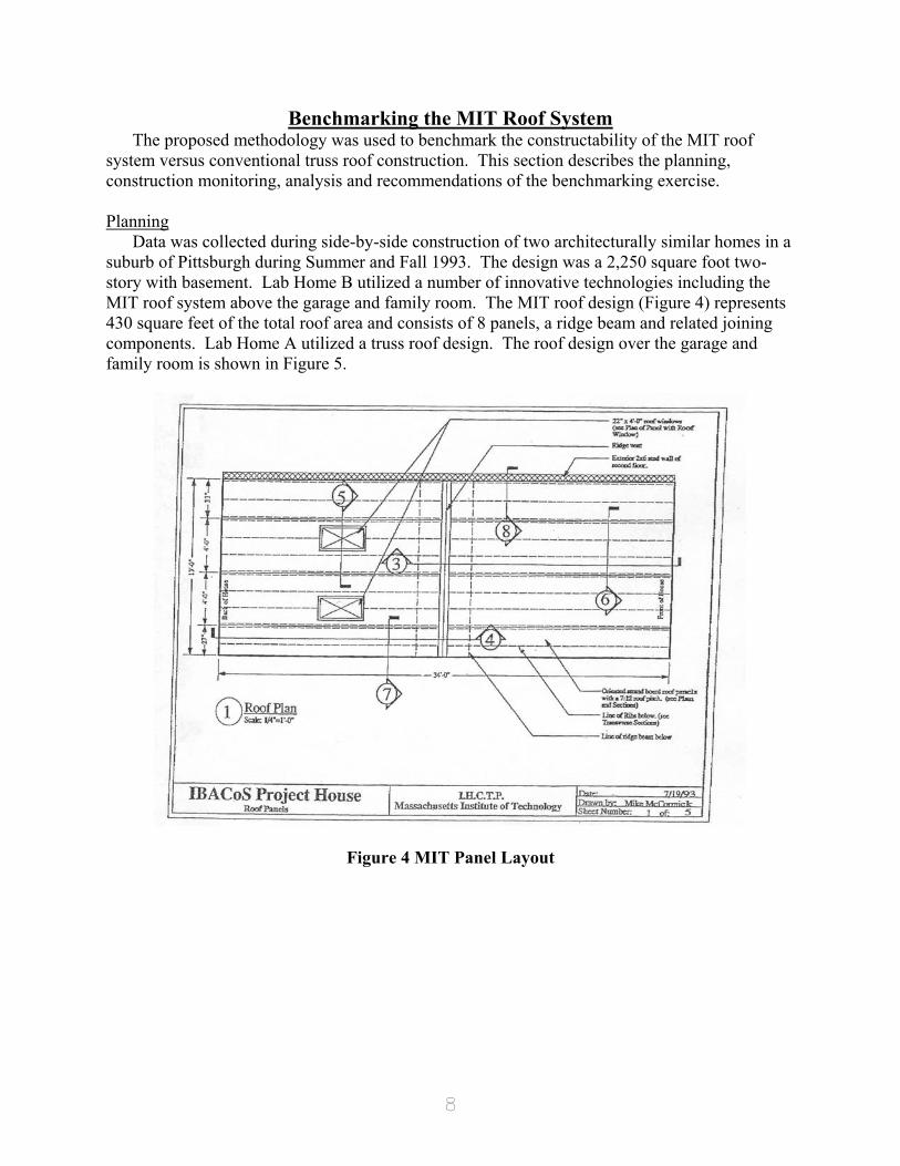
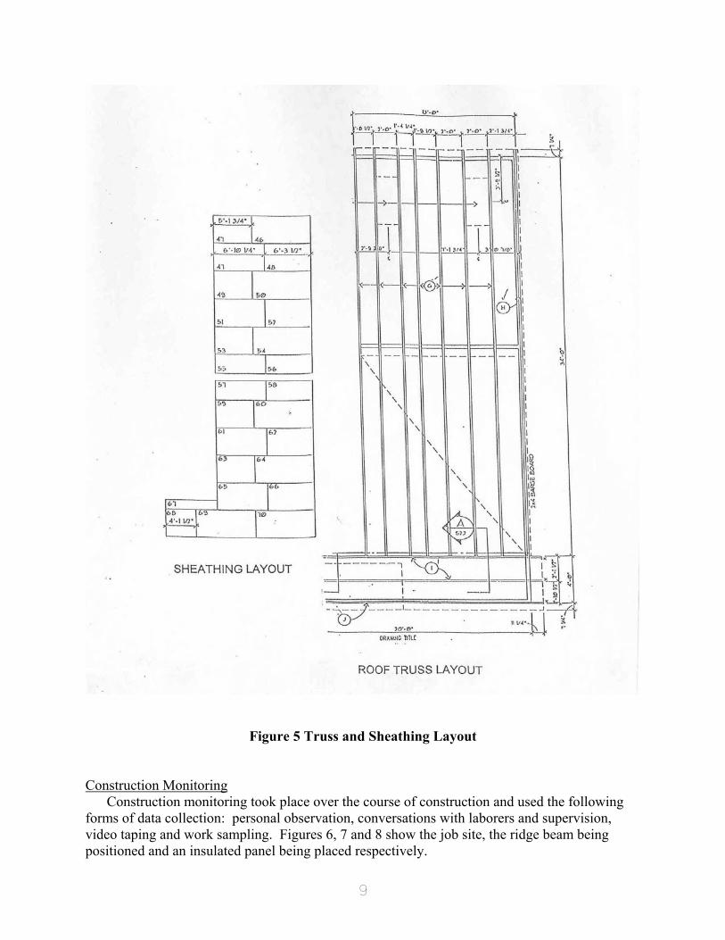
Data was collected during side-by-side construction of two architecturally similar homes in a suburb of Pittsburgh during Summer and Fall 1993. The design was a 2,250 square foot two-story with basement. Lab Home B utilized a number of innovative technologies including the MIT roof system above the garage and family room. The MIT roof design (Figure 4) represents 430 square feet of the total roof area and consists of 8 panels, a ridge beam and related joining components. Lab Home A utilized a truss roof design. The roof design over the garage and family room is shown in Figure 5.
Figure 4 MIT Panel Layout
9
Figure 5 Truss and Sheathing Layout
Construction Monitoring
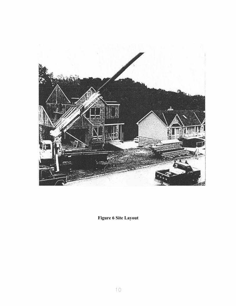
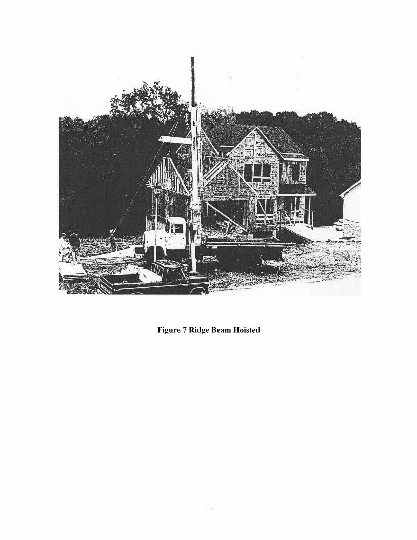
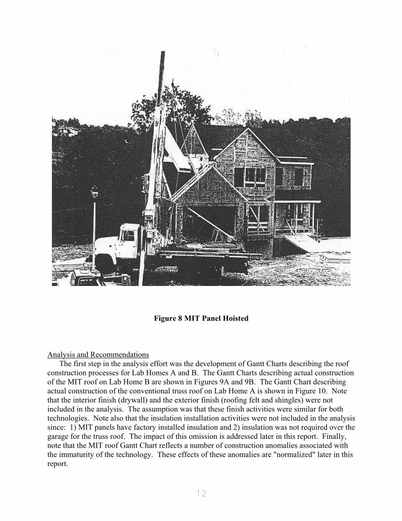
Construction monitoring took place over the course of construction and used the following forms of data collection: personal observation, conversations with laborers and supervision, video taping and work sampling. Figures 6, 7 and 8 show the job site, the ridge beam being positioned and an insulated panel being placed respectively.
10
Figure 6 Site Layout
11
Figure 7 Ridge Beam Hoisted
12
Figure 8 MIT Panel Hoisted
Analysis and Recommendations
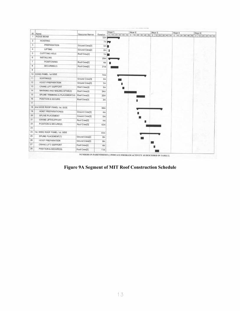
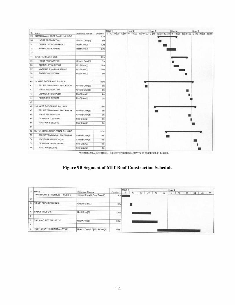
The first step in the analysis effort was the development of Gantt Charts describing the roof construction processes for Lab Homes A and B. The Gantt Charts describing actual construction of the MIT roof on Lab Home B are shown in Figures 9A and 9B. The Gantt Chart describing actual construction of the conventional truss roof on Lab Home A is shown in Figure 10. Note that the interior finish (drywall) and the exterior finish (roofing felt and shingles) were not included in the analysis. The assumption was that these finish activities were similar for both technologies. Note also that the insulation installation activities were not included in the analysis since: 1) MIT panels have factory installed insulation and 2) insulation was not required over the garage for the truss roof. The impact of this omission is addressed later in this report. Finally, note that the MIT roof Gantt Chart reflects a number of construction anomalies associated with the immaturity of the technology. These effects of these anomalies are "normalized" later in this report.
13
Figure 9A Segment of MIT Roof Construction Schedule
14
Figure 9B Segment of MIT Roof Construction Schedule
15
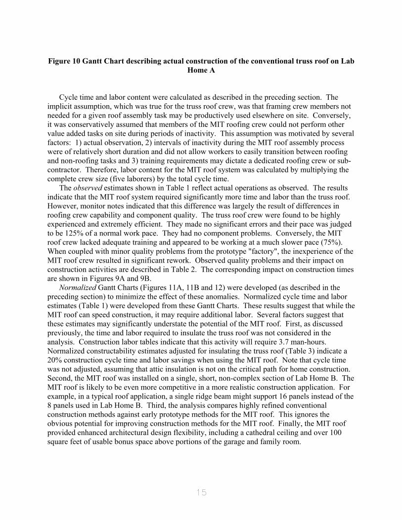
Figure 10 Gantt Chart describing actual construction of the conventional truss roof on Lab
Home A Cycle time and labor content were calculated as described in the preceding section. The
implicit assumption, which was true for the truss roof crew, was that framing crew members not needed for a given roof assembly task may be productively used elsewhere on site. Conversely, it was conservatively assumed that members of the MIT roofing crew could not perform other value added tasks on site during periods of inactivity. This assumption was motivated by several factors: 1) actual observation, 2) intervals of inactivity during the MIT roof assembly process were of relatively short duration and did not allow workers to easily transition between roofing and non-roofing tasks and 3) training requirements may dictate a dedicated roofing crew or sub-contractor. Therefore, labor content for the MIT roof system was calculated by multiplying the complete crew size (five laborers) by the total cycle time.
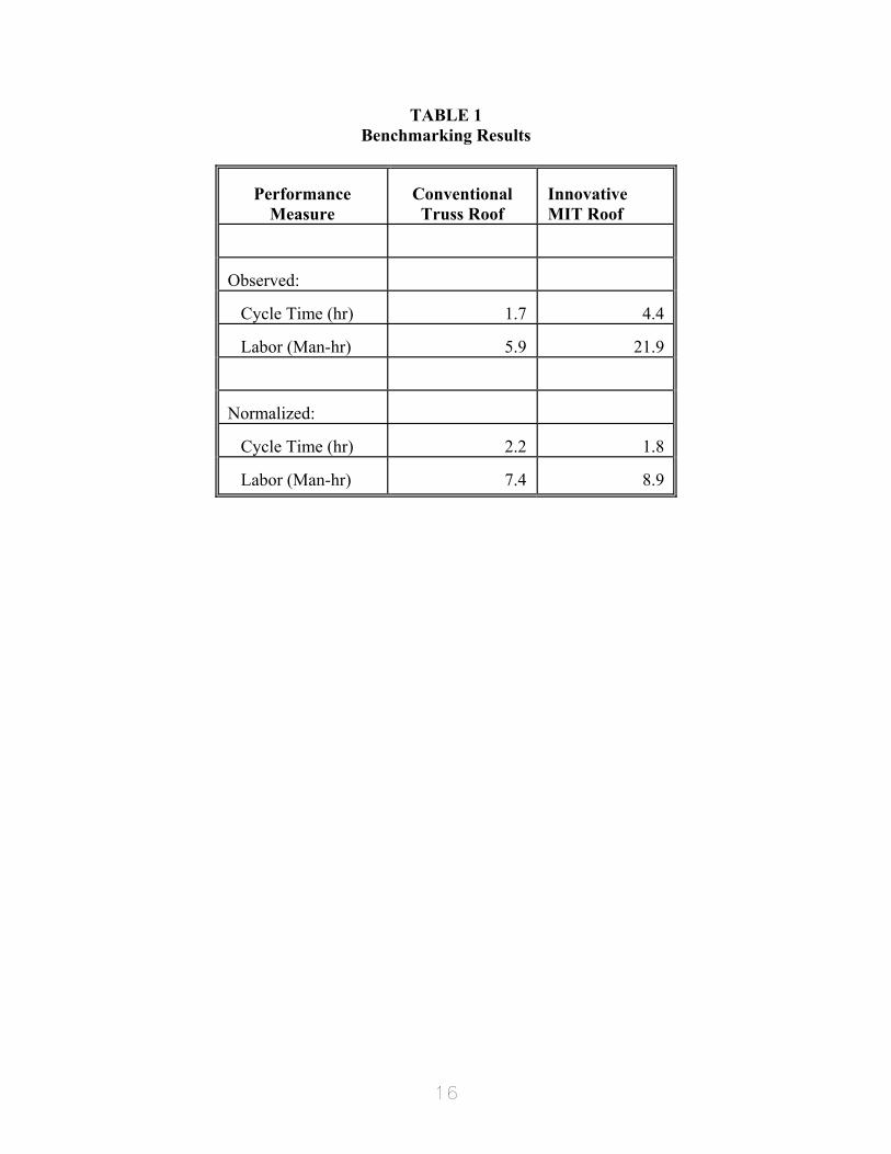
The observed estimates shown in Table 1 reflect actual operations as observed. The results indicate that the MIT roof system required significantly more time and labor than the truss roof. However, monitor notes indicated that this difference was largely the result of differences in roofing crew capability and component quality. The truss roof crew were found to be highly experienced and extremely efficient. They made no significant errors and their pace was judged to be 125% of a normal work pace. They had no component problems. Conversely, the MIT roof crew lacked adequate training and appeared to be working at a much slower pace (75%). When coupled with minor quality problems from the prototype "factory", the inexperience of the MIT roof crew resulted in significant rework. Observed quality problems and their impact on construction activities are described in Table 2. The corresponding impact on construction times are shown in Figures 9A and 9B.
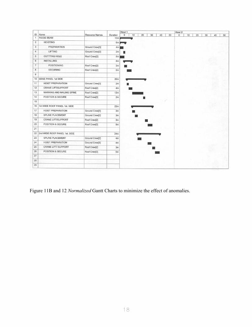
Normalized Gantt Charts (Figures 11A, 11B and 12) were developed (as described in the preceding section) to minimize the effect of these anomalies. Normalized cycle time and labor estimates (Table 1) were developed from these Gantt Charts. These results suggest that while the MIT roof can speed construction, it may require additional labor. Several factors suggest that these estimates may significantly understate the potential of the MIT roof. First, as discussed previously, the time and labor required to insulate the truss roof was not considered in the analysis. Construction labor tables indicate that this activity will require 3.7 man-hours. Normalized constructability estimates adjusted for insulating the truss roof (Table 3) indicate a 20% construction cycle time and labor savings when using the MIT roof. Note that cycle time was not adjusted, assuming that attic insulation is not on the critical path for home construction. Second, the MIT roof was installed on a single, short, non-complex section of Lab Home B. The MIT roof is likely to be even more competitive in a more realistic construction application. For example, in a typical roof application, a single ridge beam might support 16 panels instead of the 8 panels used in Lab Home B. Third, the analysis compares highly refined conventional construction methods against early prototype methods for the MIT roof. This ignores the obvious potential for improving construction methods for the MIT roof. Finally, the MIT roof provided enhanced architectural design flexibility, including a cathedral ceiling and over 100 square feet of usable bonus space above portions of the garage and family room.
16
TABLE 1 Benchmarking Results
Performance Measure
Conventional Truss Roof
Innovative MIT Roof
Observed:
Cycle Time (hr)
1.7
4.4
Labor (Man-hr)
5.9
21.9
Normalized:
Cycle Time (hr)
2.2
1.8
Labor (Man-hr)
7.4
8.9
17
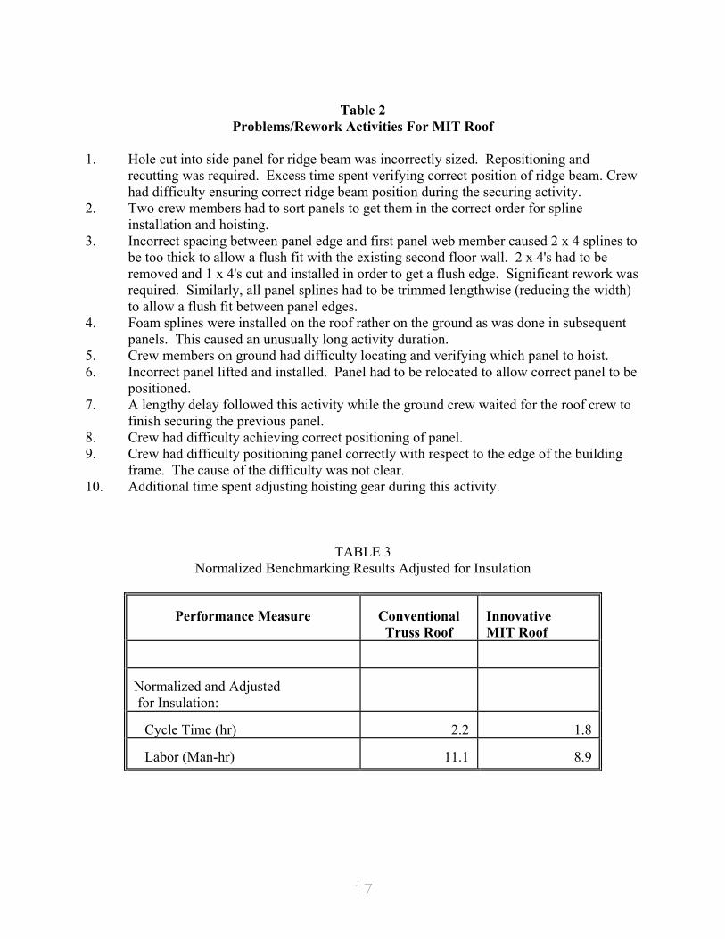
Table 2
Problems/Rework Activities For MIT Roof 1. Hole cut into side panel for ridge beam was incorrectly sized. Repositioning and
recutting was required. Excess time spent verifying correct position of ridge beam. Crew had difficulty ensuring correct ridge beam position during the securing activity.
2. Two crew members had to sort panels to get them in the correct order for spline installation and hoisting.
3. Incorrect spacing between panel edge and first panel web member caused 2 x 4 splines to be too thick to allow a flush fit with the existing second floor wall. 2 x 4's had to be removed and 1 x 4's cut and installed in order to get a flush edge. Significant rework was required. Similarly, all panel splines had to be trimmed lengthwise (reducing the width) to allow a flush fit between panel edges.
4. Foam splines were installed on the roof rather on the ground as was done in subsequent panels. This caused an unusually long activity duration.
5. Crew members on ground had difficulty locating and verifying which panel to hoist. 6. Incorrect panel lifted and installed. Panel had to be relocated to allow correct panel to be
positioned. 7. A lengthy delay followed this activity while the ground crew waited for the roof crew to
finish securing the previous panel. 8. Crew had difficulty achieving correct positioning of panel. 9. Crew had difficulty positioning panel correctly with respect to the edge of the building
frame. The cause of the difficulty was not clear. 10. Additional time spent adjusting hoisting gear during this activity.
TABLE 3 Normalized Benchmarking Results Adjusted for Insulation
Performance Measure
Conventional Truss Roof
Innovative MIT Roof
Normalized and Adjusted for Insulation:
Cycle Time (hr)
2.2
1.8
Labor (Man-hr)
11.1
8.9
18
Figure 11B and 12 Normalized Gantt Charts to minimize the effect of anomalies.
19
Conclusions Benchmarking innovative homebuilding technologies against "known" conventional
technologies can play an important role in developing builder acceptance. A formal structured approach, such as the methodology proposed in this report, can facilitate the process and improve comparability of results. Application of the methodology demonstrated the importance of adequate planning as well as the need to identify and adjust for anomalies encountered during construction. The monitor must be particularly diligent when observing emerging homebuilding technologies.
Specific results presented in this report were obtained from observations made during the construction of two laboratory homes. Within these limitations, the results suggest the potential of the MIT roof system. They also reflect that this system is still in an early prototype stage of development, suffering from minor quality problems and a poorly trained crew. Key steps toward commercialization must include an increased focus on manufacturing processes, site construction processes, quality and training.

20
Acknowledgements This research was sponsored by the United States Department of Energy, through the Energy
Efficient Industrialized Housing (EEIH) research program. The EEIH program is jointly conducted by the Center for Housing Innovation, University of Oregon, the Florida Solar Energy Center and the Department of Industrial Engineering and Management Systems, University of Central Florida (DOE Contract No. DE-FC03-89SF17960).
We would also like to thank the IBACoS group and Joe Sowinski for the opportunity to benchmark their innovative efforts.
21
References
1. B. Goldberg, Advanced Housing Technology Program: Phase 1 Report to Oak Ridge
National Laboratories, Upper Marlboro, MD: National Association of Home Builders Research Center (1991)
2. T. Toole and T. Tonyan, "The Adoption of Innovative Building Systems: A Case Study,"
Building Research Journal, Vol. 1(1), pp. 21-26 (1992) 3. J. Crowley, J. Dentz, L. Morse-Fortier, and M. Parent, "Reinventing Wood Frame
Construction: Development of an Innovative Roof Component System," Forest Products Journal, Vol. 43(7/8), pp. 27-35 (1993)
4. R.L. Armacost, M.A. Mullens, and W.W. Swart, Benchmarking the Constructability of
Innovative Homebuilding Technologies Used in the IBACoS Lab Home Construction Program, Univ. of Central Florida Dept. of Industrial Engineering Working Paper, Orlando, FL (1994)
5. R. Means, Means Building Construction Cost Data, 1993 Edition. Kingston, MA: R.S.
Means Company, Inc. (1993) 6. Hauser, J. and D. Clausing, "The house of quality," Harvard Business Review, Vol. 66(3),
pp. 63-73 (1988) 7. Moore, D., "Buildability and Skill Concept Packages: Development of a Possible Design
Tool," Building Research and Information, Vol. 21(2), p. 117 (1993) 8. M. Skibniewski and Li-Chung, "Evaluation of Advanced Construction Technology with
AHP Method," Journal of Construction Engineering and Management, Vol. 118(3), pp. 577-593 (1992)
9. M. M. Ali and T. Napier, "Evaluation Technique for Concrete Building Systems," Concrete
International, Vol. 11(7), p. 32 (1989) 10. J. Lutz, L. Chang and T. Napier, "Evaluation of New Building Technology," Journal of
Construction Engineering and Management, Vol. 116(2), pp. 281-299 (1990) 11. M.A. Mullens and D. Conlan, CE Technology Characterization for Structural Insulated
Panels, prepared for U.S. Department of Energy Office of Conservation and Renewable Energy (CE) (revised Dec. 1993)
12. A. Friedman, "Prefabrication Versus Conventional Construction in Single-Family Wood-
Frame Housing," Building Research and Information, Vol. 20(4), pp. 226-228 (1992) 13. G. Smith, F. Grobler and J. Miller, "A Comparison of Framing Productivity in Traditional
22
and Prefabricated Residential Construction," Building Research Journal, Vol. 2(1), pp. 27-39 (1993)
14. M.A. Mullens, R.L. Armacost and W.W. Swart, Benchmarking Construction Costs for
Innovative Homebuilding Technologies, Building Research Journal, Vol. 3(2), pp. 81-101(1994)
15. J. Laquatra, J. McCarty, M. Levy and P. Romano, "The Potential for Improved
Affordability and Energy Efficiency in Panelized Housing," Building Research Journal, Vol. 2(2), pp. 53-60 (1993)
16. N. Eldin and S. Egger, "Productivity Improvement Tool: Camcorders," Journal of
Construction Engineering and Management, Vol. 116(1), pp. 100-111 (1990)
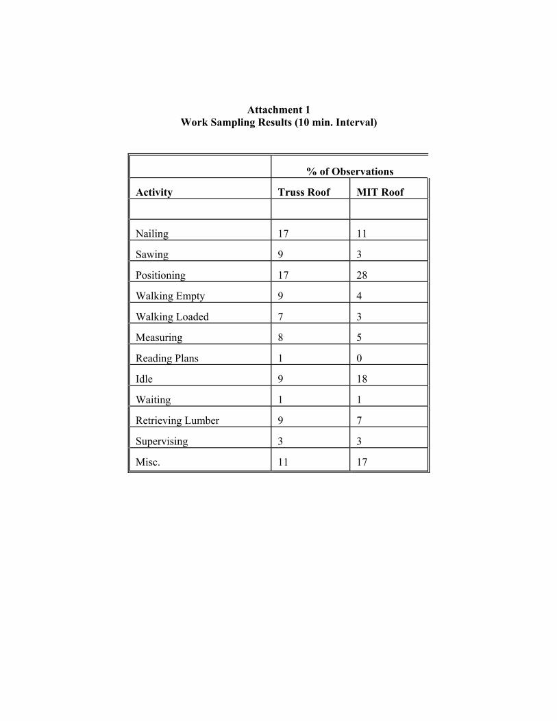
Attachment 1 Work Sampling Results (10 min. Interval)
% of Observations
Activity
Truss Roof
MIT Roof
Nailing
17
11
Sawing
9
3
Positioning
17
28
Walking Empty
9
4
Walking Loaded
7
3
Measuring
8
5
Reading Plans
1
0
Idle
9
18
Waiting
1
1
Retrieving Lumber
9
7
Supervising
3
3
Misc.
11
17