Embed Size (px)
Citation preview
Belt (mechanical) 1
Belt (mechanical)
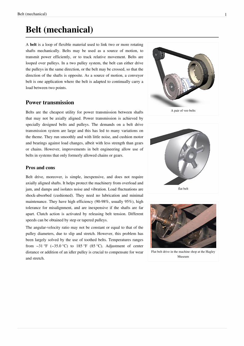
A pair of vee-belts
flat belt
Flat belt drive in the machine shop at the HagleyMuseum
A belt is a loop of flexible material used to link two or more rotatingshafts mechanically. Belts may be used as a source of motion, totransmit power efficiently, or to track relative movement. Belts arelooped over pulleys. In a two pulley system, the belt can either drivethe pulleys in the same direction, or the belt may be crossed, so that thedirection of the shafts is opposite. As a source of motion, a conveyorbelt is one application where the belt is adapted to continually carry aload between two points.
Power transmission
Belts are the cheapest utility for power transmission between shaftsthat may not be axially aligned. Power transmission is achieved byspecially designed belts and pulleys. The demands on a belt drivetransmission system are large and this has led to many variations onthe theme. They run smoothly and with little noise, and cushion motorand bearings against load changes, albeit with less strength than gearsor chains. However, improvements in belt engineering allow use ofbelts in systems that only formerly allowed chains or gears.
Pros and cons
Belt drive, moreover, is simple, inexpensive, and does not requireaxially aligned shafts. It helps protect the machinery from overload andjam, and damps and isolates noise and vibration. Load fluctuations areshock-absorbed (cushioned). They need no lubrication and minimalmaintenance. They have high efficiency (90-98%, usually 95%), hightolerance for misalignment, and are inexpensive if the shafts are farapart. Clutch action is activated by releasing belt tension. Differentspeeds can be obtained by step or tapered pulleys.The angular-velocity ratio may not be constant or equal to that of thepulley diameters, due to slip and stretch. However, this problem hasbeen largely solved by the use of toothed belts. Temperatures rangesfrom −31 °F (−35.0 °C) to 185 °F (85 °C). Adjustment of centerdistance or addition of an idler pulley is crucial to compensate for wearand stretch.

Belt (mechanical) 2
Flat belts
The drive belt: used to transfer power from theengine's flywheel. Here shown driving a
threshing machine.
Flat belts were used early in line shafting to transmit power infactories.[1] It is a simple system of power transmission that was wellsuited for its day. It delivered high power for high speeds (500 hp for10,000 ft/min), in cases of wide belts and large pulleys. These drivesare bulky, requiring high tension leading to high loads, so vee beltshave mainly replaced the flat-belts except when high speed is neededover power. The Industrial Revolution soon demanded more from thesystem, and flat belt pulleys needed to be carefully aligned to preventthe belt from slipping off. Because flat belts tend to climb towards thehigher side of the pulley, pulleys were made with a slightly convex or"crowned" surface (rather than flat) to keep the belts centered. Flatbelts also tend to slip on the pulley face when heavy loads are appliedand many proprietary dressings were available that could be applied to the belts to increase friction, and so powertransmission. Grip was better if the belt was assembled with the hair (i.e. outer) side of the leather against the pulleyalthough belts were also often given a half-twist before joining the ends (forming a Möbius strip), so that wear wasevenly distributed on both sides of the belt (DB). Belts were joined by lacing the ends together with leatherthonging,[2] [3] or later by steel comb fasteners.[4] A good modern use for a flat belt is with smaller pulleys and largecentral distances. They can connect inside and outside pulleys, and can come in both endless and jointedconstruction.
Round beltsRound belts are a circular cross section belt designed to run in a pulley with a circular (or near circular) groove. Theyare for use in low torque situations and may be purchased in various lengths or cut to length and joined, either by astaple, gluing or welding (in the case of polyurethane). Early sewing machines utilized a leather belt, joined either bya metal staple or glued, to a great effect.
Vee belts
Belts on a Yanmar 2GM20 marine diesel engine.
Vee belts (also known as V-belt or wedge rope) solved the slippageand alignment problem. It is now the basic belt for power transmission.They provide the best combination of traction, speed of movement,load of the bearings, and long service life. The V-belt was developed in1917 by John Gates of the Gates Rubber Company. They are generallyendless, and their general cross-section shape is trapezoidal. The "V"shape of the belt tracks in a mating groove in the pulley (or sheave),with the result that the belt cannot slip off. The belt also tends to wedgeinto the groove as the load increases — the greater the load, the greaterthe wedging action — improving torque transmission and making theV-belt an effective solution, needing less width and tension than flatbelts. V-belts trump flat belts with their small center distances and highreduction ratios. The preferred center distance is larger than the largestpulley diameter, but less than three times the sum of both pulleys.Optimal speed range is 1000–7000 ft/min. V-belts need larger pulleys for their larger thickness than flat belts. Theycan be supplied at various fixed lengths or as a segmented section, where the segments are linked (spliced) to form a

Belt (mechanical) 3
belt of the required length. For high-power requirements, two or more vee belts can be joined side-by-side in anarrangement called a multi-V, running on matching multi-groove sheaves. The strength of these belts is obtained byreinforcements with fibers like steel, polyester or aramid (e.g. Twaron or Kevlar). This is known as a multiple-beltdrive. When an endless belt does not fit the need, jointed and link V-belts may be employed. However they areweaker and only usable at speeds up to 4000 ft/min. A link v-belt is a number of rubberized fabric links held togetherby metal fasteners. They are length adjustable by disassembling and removing links when needed.
Multi-groove beltsA multi-groove or polygroove belt[5] is made up of usually 5 or 6 "V" shapes along side each other. This gives athinner belt for the same drive surface, thus is more flexible, although often wider. The added flexibility offers animproved efficiency, as less energy is wasted in the internal friction of continually bending the belt. In practice thisgain of efficiency is overshadowed by the reduced heating effect on the belt, as a cooler-running belt lasts longer inservice.A further advantage of the polygroove belt, and the reason they have become so popular, stems from the ability to berun over pulleys on the ungrooved back of the belt. Although this is sometimes done with vee belts and a single idlerpulley for tensioning, a polygroove belt may be wrapped around a pulley on its back tightly enough to change itsdirection, or even to provide a light driving force.[6]
Any vee belt's ability to drive pulleys depends on wrapping the belt around a sufficient angle of the pulley to providegrip. Where a single-vee belt is limited to a simple convex shape, it can adequately wrap at most three or possiblyfour pulleys, so can drive at most three accessories. Where more must be driven, such as for modern cars with powersteering and air conditioning, multiple belts are required. As the polygroove belt can be bent into concave paths byexternal idlers, it can wrap any number of driven pulleys, limited only by the power capacity of the belt.[6]
This ability to bend the belt at the designer's whim allows it to take a complex or "serpentine" path. This can assistthe design of a compact engine layout, where the accessories are mounted more closely to the engine block andwithout the need to provide movable tensioning adjustments. The entire belt may be tensioned by a single idlerpulley.
Ribbed beltA ribbed belt is a power transmission belt featuring lengthwise grooves. It operates from contact between the ribs ofthe belt and the grooves in the pulley. Its single-piece structure it reported to offer an even distribution of tensionacross the width of the pulley where the belt is in contact, a power range up to 600 kW, a high speed ratio, serpentinedrives (possibility to drive off the back of the belt), long life, stability and homogeneity of the drive tension, andreduced vibration. The ribbed belt may be fitted on various applications : compressors, fitness bikes, agriculturalmachinery, food mixers, washing machines, lawn mowers, etc.[7]
Belt (mechanical) 4
Film beltsThough often grouped with flat belts, they are actually a different kind. They consist of a very thin belt (0.5-15millimeters or 100-4000 micrometres) strip of plastic and occasionally rubber. They are generally intended forlow-power (10 hp or 7 kW), high-speed uses, allowing high efficiency (up to 98%) and long life. These are seen inbusiness machines, printers, tape recorders, and other light-duty operations.
Timing belts
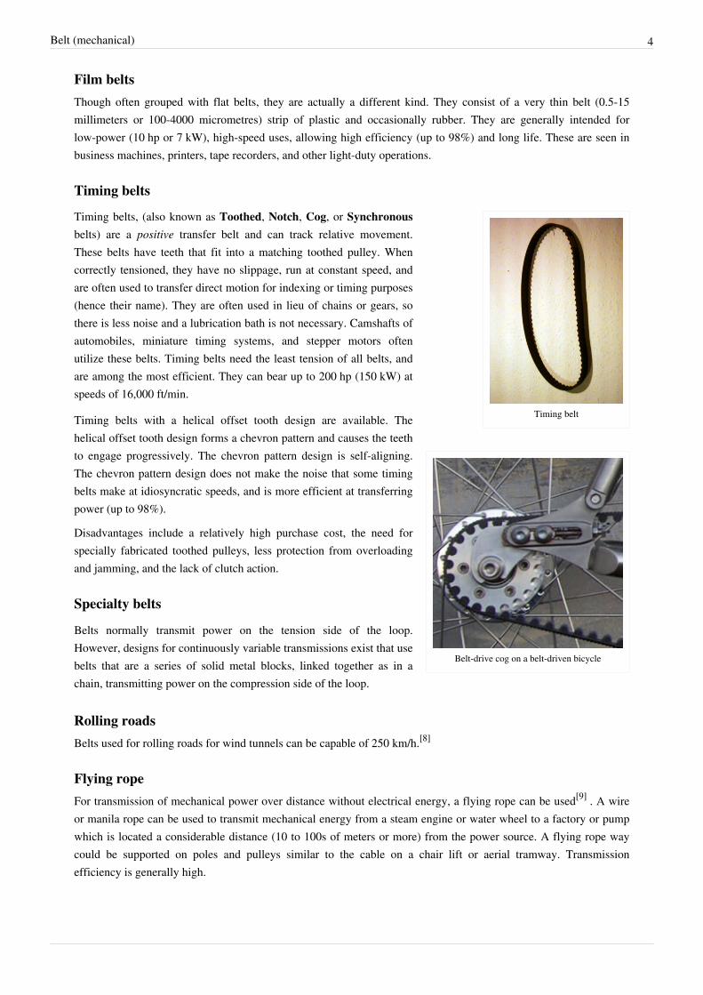
Timing belt
Belt-drive cog on a belt-driven bicycle
Timing belts, (also known as Toothed, Notch, Cog, or Synchronousbelts) are a positive transfer belt and can track relative movement.These belts have teeth that fit into a matching toothed pulley. Whencorrectly tensioned, they have no slippage, run at constant speed, andare often used to transfer direct motion for indexing or timing purposes(hence their name). They are often used in lieu of chains or gears, sothere is less noise and a lubrication bath is not necessary. Camshafts ofautomobiles, miniature timing systems, and stepper motors oftenutilize these belts. Timing belts need the least tension of all belts, andare among the most efficient. They can bear up to 200 hp (150 kW) atspeeds of 16,000 ft/min.
Timing belts with a helical offset tooth design are available. Thehelical offset tooth design forms a chevron pattern and causes the teethto engage progressively. The chevron pattern design is self-aligning.The chevron pattern design does not make the noise that some timingbelts make at idiosyncratic speeds, and is more efficient at transferringpower (up to 98%).
Disadvantages include a relatively high purchase cost, the need forspecially fabricated toothed pulleys, less protection from overloadingand jamming, and the lack of clutch action.
Specialty belts
Belts normally transmit power on the tension side of the loop.However, designs for continuously variable transmissions exist that usebelts that are a series of solid metal blocks, linked together as in achain, transmitting power on the compression side of the loop.
Rolling roadsBelts used for rolling roads for wind tunnels can be capable of 250 km/h.[8]
Flying ropeFor transmission of mechanical power over distance without electrical energy, a flying rope can be used[9] . A wireor manila rope can be used to transmit mechanical energy from a steam engine or water wheel to a factory or pumpwhich is located a considerable distance (10 to 100s of meters or more) from the power source. A flying rope waycould be supported on poles and pulleys similar to the cable on a chair lift or aerial tramway. Transmissionefficiency is generally high.
Belt (mechanical) 5
Standards for useThe open belt drive has parallel shafts rotating in the same direction, whereas the cross-belt drive also bears parallelshafts but rotate in opposite direction. The former is far more common, and the latter not appropriate for timing andstandard V-belts, because the pulleys contact both the both inner and outer belt surfaces. Nonparallel shafts can beconnected if the belt's center line is aligned with the center plane of the pulley. Industrial belts are usually reinforcedrubber but sometimes leather types, non-leather non-reinforced belts, can only be used in light applications.The pitch line is the line between the inner and outer surfaces that is neither subject to tension (like the outer surface)nor compression (like the inner). It is midway through the surfaces in film and flat belts and dependent oncross-sectional shape and size in timing and V-belts. Calculating pitch diameter is an engineering task and is beyondthe scope of this article. The angular speed is inversely proportional to size, so the larger the one wheel, the lessangular velocity, and vice versa. Actual pulley speeds tend to be 0.5–1% less than generally calculated because ofbelt slip and stretch. In timing belts, the inverse ratio teeth of the belt contributes to the exact measurement. Thespeed of the belt is:Speed = Circumference based on pitch diameter × angular speed in rpm
Selection criteriaBelt drives are built under the following required conditions: speeds of and power transmitted between drive anddriven unit; suitable distance between shafts; and appropriate operating conditions. The equation for power is:power (kW) = (torque in newton-meters) × (rpm) × (2π radians)/(60 sec × 1000 W)Factors of power adjustment include speed ratio; shaft distance (long or short); type of drive unit (electric motor,internal combustion engine); service environment (oily, wet, dusty); driven unit loads (jerky, shock, reversed); andpulley-belt arrangement (open, crossed, turned). These are found in engineering handbooks and manufacturer'sliterature. When corrected, the horsepower is compared to rated horsepowers of the standard belt cross sections atparticular belt speeds to find a number of arrays that will perform best. Now the pulley diameters are chosen. It isgenerally either large diameters or large cross section that are chosen, since, as stated earlier, larger belts transmitthis same power at low belt speeds as smaller belts do at high speeds. To keep the driving part at its smallest,minimum-diameter pulleys are desired. Minimum pulley diameters are limited by the elongation of the belt's outerfibers as the belt wraps around the pulleys. Small pulleys increase this elongation, greatly reducing belt life.Minimum pulley diameters are often listed with each cross section and speed, or listed separately by belt crosssection. After the cheapest diameters and belt section are chosen, the belt length is computed. If endless belts areused, the desired shaft spacing may need adjusting to accommodate standard length belts. It is often moreeconomical to use two or more juxtaposed V-belts, rather than one larger belt.In large speed ratios or small central distances, the angle of contact between the belt and pulley may be less than180°. If this is the case, the drive power must be further increased, according to manufacturer's tables, and theselection process repeated. This is because power capacities are based on the standard of a 180° contact angle.Smaller contact angles mean less area for the belt to obtain traction, and thus the belt carries less power.

Belt (mechanical) 6
Belt frictionBelt drives depend on friction to operate but, if the friction is excessive, there will be waste of energy and rapid wearof the belt. Factors which affect belt friction include belt tension, contact angle and the materials from which the beltand pulleys are made.
Belt tensionPower transmission is a function of belt tension. However, also increasing with tension is stress (load) on the beltand bearings. The ideal belt is that of the lowest tension which does not slip in high loads. Belt tensions should alsobe adjusted to belt type, size, speed, and pulley diameters. Belt tension is determined by measuring the force todeflect the belt a given distance per inch of pulley. Timing belts need only adequate tension to keep the belt incontact with the pulley.
Belt wearFatigue, more so than abrasion, is the culprit for most belt problems. This wear is caused by stress from rollingaround the pulleys. High belt tension; excessive slippage; adverse environmental conditions; and belt overloadscaused by shock, vibration, or belt slapping all contribute to belt fatigue.
SpecificationsTo fully specify a belt, the material, length, and cross-section size and shape are required. Timing belts, in addition,require that the size of the teeth be given. The length of the belt is the sum of the central length of the system on bothsides, half the circumference of both pulleys, and the square of the sum (if crossed) or the difference (if open) of theradii. Thus, when dividing by the central distance, it can be visualized as the central distance times the height thatgives the same squared value of the radius difference on, of course, both sides. When adding to the length of eitherside, the length of the belt increases, in a similar manner to the Pythagorean theorem. One important concept toremember is that as D1 gets closer to D2 there is less of a distance (and therefore less addition of length) until itsapproaches zero.On the other hand, in a crossed belt drive the sum rather than the difference of radii is the basis for computation forlength. So the wider the small drive increases, the belt length is higher.
See also• Belt track• Conveyor belt• Gilmer belt• Lariat chain - a science exhibit showing the effects when a belt is run 'too fast'• Roller chain• Timing belt

Belt (mechanical) 7
References[1] By Rhys Jenkins, Newcomen Society, (1971). Links in the History of Engineering and Technology from Tudor Times, Ayer Publishing. Page
34, ISBN 0836921674[2] James N. Boblenz. "How to lace a flat belt" (http:/ / www. farmcollector. com/ Looking-Back/ How-To-Lace-A-Flat-Belt. aspx). Farm
Collector. . Retrieved 2010-04-04.[3] "Belt lacing patterns" (http:/ / www. ag. ndsu. nodak. edu/ abeng/ plans/ nd4041-1. pdf) (PDF). North Dakota Statue Univ.. .[4] "Flat Belt Pulleys, Belting, Splicing" (http:/ / www. hitnmiss. com/ 25a. html). . Retrieved 2010-04-04.[5] DIN 7867[6] Automotive Handbook (3rd ed.). Robert Bosch GmbH. 1993. p. 304. ISBN 0-8376-0330-7.[7] "Hutchinson Transmission" (http:/ / www. hutchinsontransmission. com). . Retrieved 2009-12-22.[8] "Pininfarina Aerodynamic and Aeroacoustic Research Center" (http:/ / arc. pininfarina. it/ english/ news. html). Arc.pininfarina.it. . Retrieved
2009-10-24.[9] John Joseph Flather (1895). Rope-driving: a treatise on the transmission of power by means of fibrous ropes (http:/ / books. google. com/
books?id=hQ9IAAAAIAAJ& pg=PA161& lpg=PA161& dq="flying+ rope"+ transmission& source=bl& ots=kWkgZ4dCTQ&sig=--3c5gCzFOmolLHuJu3CFNePucA& hl=en& ei=FTd_S_u8LoyKsgPR4t37Cw& sa=X& oi=book_result& ct=result& resnum=1&ved=0CAkQ6AEwAA#v=onepage& q="flying rope" transmission& f=false). .


![INDEX [ ] Web view“conveyor belt installation” means a mechanical system used for the transportation of minerals, material, or persons on a belt](https://img.pdfslide.us/doc/110x75/5a70d52d7f8b9a9d538c5930/index-wwwcompliancetoolscozawwwcompliancetoolscoza013september2013minindoc.jpg)