Embed Size (px)
Citation preview
http://www.iaeme.com/IJARET/index.asp 330 [email protected]
International Journal of Advanced Research in Engineering and Technology (IJARET) Volume 11, Issue 2, February 2020, pp. 330-355, Article ID: IJARET_11_02_032
Available online at http://www.iaeme.com/IJARET/issues.asp?JType=IJARET&VType=11&IType=2
Journal Impact Factor (2020): 10.9475 (Calculated by GISI) www.jifactor.com
ISSN Print: 0976-6480 and ISSN Online: 0976-6499
© IAEME Publication Scopus Indexed
BEHAVIOUR OF RECTANGULAR CONCRETE
BEAMS REINFORCED INTERNALLY WITH
HFRP REINFORCEMENTS UNDER PURE
TORSION
P. Kapildev*
Research Scholar, Department of Civil & Structural Engineering,
Annamalai University, Annamalainagar, India.
G. Kumaran
Department of Civil & Structural Engineering,
Annamalai University, Annamalainagar, India.
*Corresponding Author Email: [email protected]
ABSTRACT
Finite Element Modelling and analysis of rectangular concrete beams reinforced
internally with Hybrid Fibre Reinforced Polymer (HFRP) reinforcements under pure
torsion is carried out in this study. Different parameters like grade of concrete, beam
longitudinal reinforcement ratio and transverse stirrups spicing are considered. The
basic strength properties of concrete, steel and HFRP reinforcements are determined
experimentally. Experimental torque verses twist relationship is established for
various values of torque and twist using elastic, plastic theories of torsion. Finally the
ultimate torque is determined using experimentaly for different parameters considered
in this study. Based on this study, a good agreement is made between finite element
analysis and the experimental behaviour.
Keywords: pure torsion; beam; HFRP reinforcements; steel; Experimental model
Cite this Article: P. Kapildev and G. Kumaran, Behaviour of Rectangular Concrete
Beams Reinforced Internally with HFRP Reinforcements Under Pure Torsion,
International Journal of Advanced Research in Engineering and Technology
(IJARET), 11 (2), 2020, pp 330-355.
http://www.iaeme.com/IJARET/issues.asp?JType=IJARET&VType=11&IType=2
1. INTRODUCTION
Fibre Reinforced Polymer (FRP) materials are becoming a new age material for concrete
structures. Its use has been recommended in ACI codes. But in India its applicability is rare in
view of the few manufacturers and lacking in commercial viability. The advantages of the
FRP materials lie in their better structural performance especially in aggressive environmental
Behaviour of Rectangular Concrete Beams Reinforced Internally with HFRP Reinforcements
Under Pure Torsion
http://www.iaeme.com/IJARET/index.asp 331 [email protected]
conditions in terms of strength and durability (Machida 1993; ACI 440R96 1996; Nanni
1993). FRP materials are commercially available in the form of cables, sheets, plates etc. But
in the recent times FRPs are available in the form of bars which are manufactured by
pultrusion process which are used as internal reinforcements as an alternate to the
conventional steel reinforcements. These FRP bars are manufactured with different surface
imperfections to develop good bond between the bar and the surrounding concrete. Fibre
reinforcements are well recognised as a vital constituent of the modern concrete structures.
FRP reinforcements are now being used in increasing numbers all over the world, including
India. FRP reinforcements are preferred by structural designers for the construction of
seawalls, industrial roof decks, base pads for electrical and reactor equipment and concrete
floor slabs in aggressive chemical environments owing to their durable properties.
Due to the advantages of FRP reinforcements in mind, many research works have been
carried out throughout the world on the use of FRP reinforcing bars in the structural concrete
flexural elements like slabs, beams, etc. (Nawy et al., 1997; Faza and GangaRao, 1992;
Benmokrane, 1995; Sivagamasundari et al., 2008; Deiveegan et al., 2010; Saravanan et al.,
2011). Therefore the present study discusses mainly on the behaviour of beams reinforced
internally with Glass Fibre Reinforced Polymer (HFRP) reinforcements under pure torsion.
The scope of the present study is restricted to with the HFRP reinforcements because of their
availability in India. First part of this study covers the theoretical analysis based on the
existing using space truss formulation for conventionally reinforced beams. Second part of
this study is related to the finite element modelling and analysis of HFRP/Steel reinforced
concrete beams. Finite element modelling is done with the help of ANSYS software with
different parametric conditions (Sivagamasundari et al., 2008; Deiveegan et al., 2010;
Saravanan et al., 2011). Finally, the results are summarised based on the Finite element
analysis and the theoretical analysis and are validated with the existing theories.
2. MATERIALS
2.1. Concrete
Normal Strength Concrete (NSC) of grades M30 and M60 are used in this study. Ordinary
Portland cement is used to prepare the concrete. The maximum size of aggregate used is 20
mm and the size of fine aggregate as M-sand ranges between 0 and 4.75 mm. After casting,
the specimens are allowed to cure in real environmental conditions for about 28 days so as to
attain strength. The test specimens are generally tested after a curing period of 28 days. The
strength of concrete under uniaxial compression is determined by loading ‗standard test
cubes‘ (150 mm size) to failure in a compression testing machine, as per IS 516 1959. The
modulus of elasticity of concrete is determined by loading ‗standard cylinders‘ (150 mm
diameter and 200 mm long) to failure in a compression testing machine, as per IS 516: 1959.
The mix proportions of the NSC are carried out as per Indian Standards (IS) 102621982 and
the average compressive strengths are obtained from laboratory tests (Sivagamasundari et al.,
2008; Deiveegan et al., 2010; Saravanan et al., 2011) and are depicted in Table 1(a).
Table 1 Properties of Concrete
Material/m3
M30 grade of
concrete
Ratio M60 grade of
concrete
Ratio
Cement 368.42kg
1:1.87:3.50
466.67 kg
1:1.36:2.70
Fine aggregate 690.04 kg 629.16 kg
Coarse aggregate 1290.988 kg 1263.55 kg
Water/cement ratio 0.38 0.30
Average compressive
strength of concrete cubes 42.00 MPa 76.00 MPa
P. Kapildev and G. Kumaran
http://www.iaeme.com/IJARET/index.asp 332 [email protected]
2.2. Reinforcements
The mechanical properties of all the types of HFRP reinforcements as per ASTMD 391684
Standards and steel specimens as per Indian standards are obtained from laboratory tests and
the results are tabulated in Table 1(b). The tensile strength of steel reinforcements (S) used in
this study, conforming to Indian standards and having an average value of the yield strength
of steel is considered for this study. HFRP reinforcements used in this study are manufactured
by pultrusion process with the Eglass fibre volume approximately 60% and these fibres are
reinforced with epoxy resins. Previous studies were carried out with three different types of
GFRP reinforcements (grooved, sand sprinkled & threaded) (ACI 440R96; Muthuramu , et
al., 2005; Sivagamasundari et al., 2008; Deiveegan et al., 2010; Saravanan et al., 2011) with
different surface indentations and are designated as Fg, Fs and Ft. In this study threaded type
HFRP reinforcement is used in place of conventional steel. The diameters of the longitudinal
and transverse reinforcements are 10 mm and 8 mm respectively. The standard minimum
diameters of the reinforcements as per Indian standards are adopted in this study. The tensile
strength properties are ascertained as per ACI standards shown in Table1(b) and are validated
by conducting the tensile tests at SERC, Chennai. The compressive modulus of elasticity of
GFRP reinforcing bars is smaller than its tensile modulus of elasticity (ACI 440R96;
Lawrence C Bank 2006; Sivagamasundari et al., 2008). It varies between 36 47 GPa which is
approximately 70% of the tensile modulus for GFRP reinforcements. Under compression
GFRP reinforcements have shown a premature failures resulting from end brooming and
internal fibre microbuckling. In this study, GFRP stirrups are manufactured by Vacuum
Assisted Resin Transfer Moulding process, using glass fibres reinforced with epoxy resin
(ACI 440R96; Sivagamasundari et al., 2008; Deiveegan et al., 2010; Saravanan et al., 2011).
Based on the experimental study, it is observed that the strength of GFRP stirrups at the bend
location (bend strength) is as low as 50 % of the strength parallel to the fibres. However, the
stirrup strength in straight portion is comparable to the yield strength of conventional steel
stirrups. Therefore, in this study, HFRP stirrups strength is taken as 30% of its tensile strength
i.e 150 MPa.
Table 2 Properties of reinforcements
Properties Sand coated Hybrid
FRP rod (Hf) Steel Fe 500 rod (Fe)
Tensile strength (MPa) 1052.04 520
Longitudinal Elastic modulus
(GPa) 64.70 210
Strain 0.012 0.002
Poisson‘s ratio 0.236 0.3
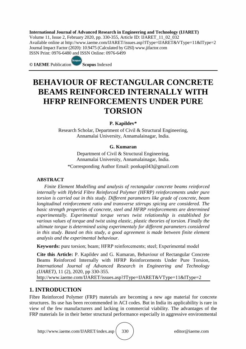
Figure 1 HFRP reinforcements with end anchorages for tensile tests
Behaviour of Rectangular Concrete Beams Reinforced Internally with HFRP Reinforcements
Under Pure Torsion
http://www.iaeme.com/IJARET/index.asp 333 [email protected]
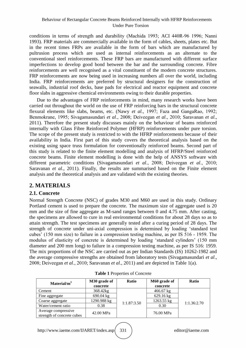
Figure 2 Failure of HFRP reinforcements tensile test
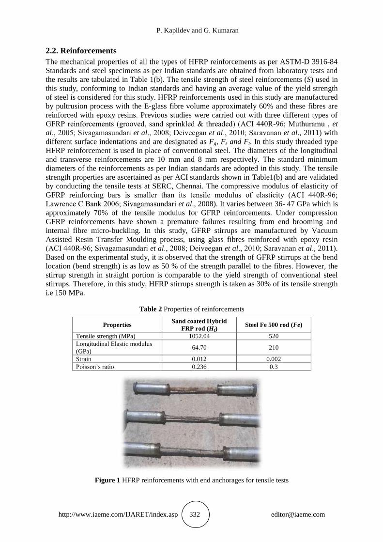
Stress-Strain Curve of Fe 500 steel Sand coated Hybrid FRP Reinforcements (Hf)
Figure 3 StressStrain curve for all the reinforcements involved in the present study
3. THEORETICAL IDEALISATION OF TORQUE –TWIST (T– ) CURVE
3.1. Theoretical Investigation
Theoretical torque verses twist relationship is established for various values of torque and
twist using elastic, plastic theories of torsion and also the ultimate torque is determined using
space truss analogy (Hsu 1968; MacGregor et al., 1995; Rasmussen et al., 1995; Ashar et al.,
1996; Khaldown et al., 1996; Liang et al., 2000; Trahait 2005; Luis et al., 2008; Chyuan
2010).
The theoretical investigation consists different rectangular beams and are designated are
as follows; Bp1m1S1Fe; Bp1m1S1Hf ;Bp1m2S1Fe; Bp1m2S1Hf ; Bp2m1S1Fe; Bp2m1S1Hf ;
Bp2m2S1Fe; Bp2m2S1Hf ; Bp1m1S2Fe; Bp1m1S2Hf ;Bp1m2S2Fe; Bp1m2S2Hf; Bp2m1S2Fe;
Bp2m1S2Hf ; Bp2m2S2Fe; Bp2m2S2Hf.
These beams are reinforced internally with threaded type Hybrid Fibre Reinforced
Polymer Reinforcements and conventional steel reinforcements with different grades of
concrete and steel reinforcement ratio under pure torsion is considered in this study. The
P. Kapildev and G. Kumaran
http://www.iaeme.com/IJARET/index.asp 334 [email protected]
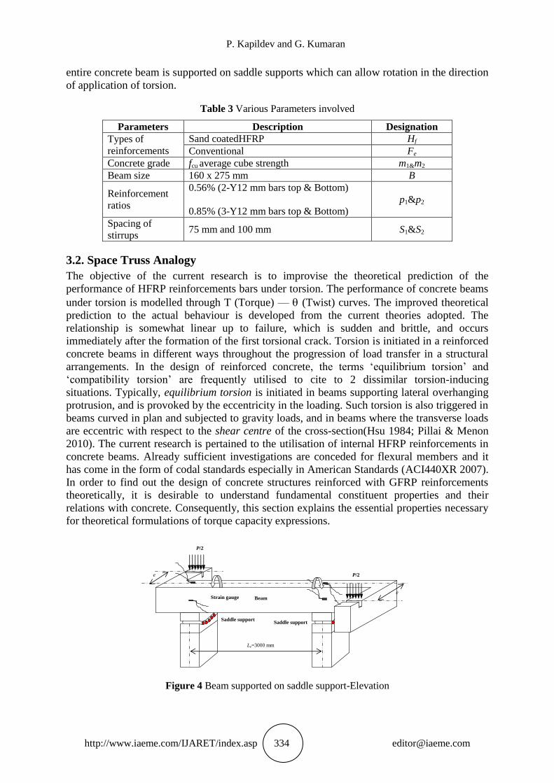
entire concrete beam is supported on saddle supports which can allow rotation in the direction
of application of torsion.
Table 3 Various Parameters involved
Parameters Description Designation
Types of
reinforcements
Sand coatedHFRP Hf
Conventional Fe
Concrete grade fcu average cube strength m1&m2
Beam size 160 x 275 mm B
Reinforcement
ratios
0.56% (2-Y12 mm bars top & Bottom)
0.85% (3-Y12 mm bars top & Bottom)
p1&p2
Spacing of
stirrups 75 mm and 100 mm S1&S2
3.2. Space Truss Analogy
The objective of the current research is to improvise the theoretical prediction of the
performance of HFRP reinforcements bars under torsion. The performance of concrete beams
under torsion is modelled through T (Torque) — (Twist) curves. The improved theoretical
prediction to the actual behaviour is developed from the current theories adopted. The
relationship is somewhat linear up to failure, which is sudden and brittle, and occurs
immediately after the formation of the first torsional crack. Torsion is initiated in a reinforced
concrete beams in different ways throughout the progression of load transfer in a structural
arrangements. In the design of reinforced concrete, the terms ‗equilibrium torsion‘ and
‗compatibility torsion‘ are frequently utilised to cite to 2 dissimilar torsion-inducing
situations. Typically, equilibrium torsion is initiated in beams supporting lateral overhanging
protrusion, and is provoked by the eccentricity in the loading. Such torsion is also triggered in
beams curved in plan and subjected to gravity loads, and in beams where the transverse loads
are eccentric with respect to the shear centre of the cross-section(Hsu 1984; Pillai & Menon
2010). The current research is pertained to the utilisation of internal HFRP reinforcements in
concrete beams. Already sufficient investigations are conceded for flexural members and it
has come in the form of codal standards especially in American Standards (ACI440XR 2007).
In order to find out the design of concrete structures reinforced with GFRP reinforcements
theoretically, it is desirable to understand fundamental constituent properties and their
relations with concrete. Consequently, this section explains the essential properties necessary
for theoretical formulations of torque capacity expressions.
Le=3000 mm
e
P/2
P/2
e
Support
Saddle support
Beam
Support
Saddle support
Strain gauge
Figure 4 Beam supported on saddle support-Elevation
Behaviour of Rectangular Concrete Beams Reinforced Internally with HFRP Reinforcements
Under Pure Torsion
http://www.iaeme.com/IJARET/index.asp 335 [email protected]
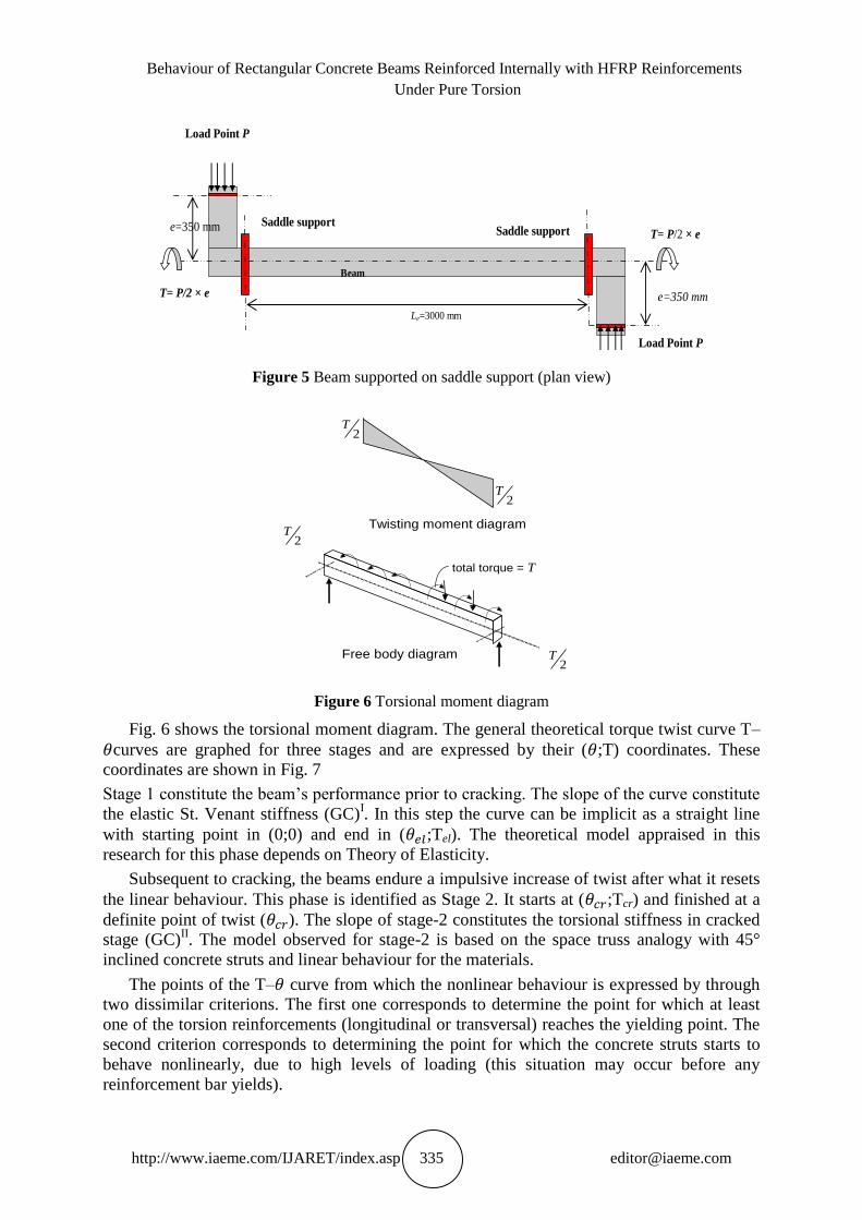
e=350 mm
e=350 mm
Le=3000 mm
Saddle support
Beam
Load Point P
T= P/2 × e
T= P/2 × e
Load Point P
Saddle support
Figure 5 Beam supported on saddle support (plan view)
Twisting moment diagram
T2
Free body diagram
total torque = T
T2
T2
T2
Figure 6 Torsional moment diagram
Fig. 6 shows the torsional moment diagram. The general theoretical torque twist curve T–
curves are graphed for three stages and are expressed by their ( ;T) coordinates. These
coordinates are shown in Fig. 7
Stage 1 constitute the beam‘s performance prior to cracking. The slope of the curve constitute
the elastic St. Venant stiffness (GC)I. In this step the curve can be implicit as a straight line
with starting point in (0;0) and end in ( ;Tel). The theoretical model appraised in this
research for this phase depends on Theory of Elasticity.
Subsequent to cracking, the beams endure a impulsive increase of twist after what it resets
the linear behaviour. This phase is identified as Stage 2. It starts at ( ;Tcr) and finished at a
definite point of twist ( ). The slope of stage-2 constitutes the torsional stiffness in cracked
stage (GC)II. The model observed for stage-2 is based on the space truss analogy with 45°
inclined concrete struts and linear behaviour for the materials.
The points of the T– curve from which the nonlinear behaviour is expressed by through
two dissimilar criterions. The first one corresponds to determine the point for which at least
one of the torsion reinforcements (longitudinal or transversal) reaches the yielding point. The
second criterion corresponds to determining the point for which the concrete struts starts to
behave nonlinearly, due to high levels of loading (this situation may occur before any
reinforcement bar yields).
P. Kapildev and G. Kumaran
http://www.iaeme.com/IJARET/index.asp 336 [email protected]
Stage 3 of the curve was plotted by using the Variable Angle Truss-Model, with non linear
behaviour of the materials and considering the Softening Effect.
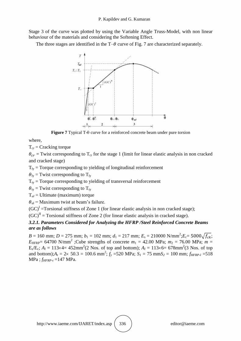
The three stages are identified in the T– curve of Fig. 7 are characterized separately.
Figure 7 Typical T- curve for a reinforced concrete beam under pure torsion
where,
Tcr = Cracking torque
= Twist corresponding to Tcr for the stage 1 (limit for linear elastic analysis in non cracked
and cracked stage)
Tly = Torque corresponding to yielding of longitudinal reinforcement
ly = Twist corresponding to Tly
Tty = Torque corresponding to yielding of transversal reinforcement
ty = Twist corresponding to Tty
Tul = Ultimate (maximum) torque
ul = Maximum twist at beam‘s failure.
(GC)I =Torsional stiffness of Zone 1 (for linear elastic analysis in non cracked stage);
(GC)II = Torsional stiffness of Zone 2 (for linear elastic analysis in cracked stage).
3.2.1. Parameters Considered for Analyzing the HFRP /Steel Reinforced Concrete Beams
are as follows
B = 160 mm; D = 275 mm; b1 = 102 mm; d1 = 217 mm; Es = 210000 N/mm2;Ec= √ ;
EHFRP= 64700 N/mm2 ;Cube strengths of concrete m1 = 42.00 MPa; m2 = 76.00 MPa; m =
Es/Ec; Al = 1134= 452mm2(2 Nos. of top and bottom); Al = 1136= 678mm
2(3 Nos. of top
and bottom);At = 2 50.3 = 100.6 mm2; fy =520 MPa; S1 = 75 mmS2 = 100 mm; fHFRP-l =518
MPa ; fHFRP-t =147 MPa.
Behaviour of Rectangular Concrete Beams Reinforced Internally with HFRP Reinforcements
Under Pure Torsion
http://www.iaeme.com/IJARET/index.asp 337 [email protected]
Table 4 Torque verses twist for various Parameters involved
Beams Tel el Tcr1 cr1 Teff eff Tyt yt Tul ul
Bp1m1FeS1 2.05 0.135 7.35 0.243 8.19 0.541 13.43 5.046 16.27 9.11
Bp1m1HfS1 2.05 0.135 7.35 0.243 8.19 0.541 12.30 14.59 9.91 11.68
Bp1m2FeS1 2.75 0.129 9.89 0.231 11.0 0.515 13.43 5.046 18.27 8.04
Bp1m2HfS1 2.75 0.129 9.89 0.231 11.0 0.515 12.30 14.54 9.91 12.62
Bp2m1FeS1 2.05 0.135 7.35 0.243 8.29 0.547 13.43 3.835 22.93 3.69
Bp2m1HfS1 2.05 0.135 7.35 0.243 8.29 0.547 12.30 10.99 11.26 7.31
Bp2m2FeS1 2.75 0.129 9.89 0.231 11.2 0.521 13.43 3.835 32.93 5.60
Bp2m2HfS1 2.75 0.129 9.89 0.231 11.2 0.521 12.30 10.94 13.26 7.23
Bp1m1FeS2 2.05 0.135 7.36 0.242 8.04 0.531 10.07 4.088 22.09 9.72
Bp1m1HfS2 2.05 0.135 7.36 0.242 8.04 0.531 9.23 11.85 7.48 13.62
Bp1m2FeS2 2.75 0.129 9.89 0.231 11.0 0.505 10.08 4.044 19.10 9.66
Bp1m2HfS2 2.75 0.129 9.89 0.231 10.8 0.505 9.23 11.81 8.91 13.52
Bp2m1FeS2 2.05 0.135 7.35 0.243 8.14 0.537 10.07 3.18 24.46 4.45
Bp2m1HfS2 2.05 0.135 7.35 0.243 8.14 0.537 9.23 9.14 14.81 6.67
Bp2m2FeS2 2.75 0.128 9.89 0.231 10.9 0.511 10.07 3.14 27.26 4.17
Bp2m2HfS2 2.75 0.128 9.89 0.231 10.9 0.511 9.23 9.11 18.81 9.60
4. EXPERIMENTAL OBSERVATIONS
4.1. Test Setup
All the test specimens are instrumented to measure their overall twist and axial deformations
using dial gauges and LVDTs. The geometry and reinforcement details of test specimens are
shown in Figs. 3.17 to 3.18.
Static Loading
Torsion testing frame of capacity 10 tonnes is used for testing the rectangular solid beam
specimens. The static monotonically increasing loads are applied at the ends with the help of
hydraulic jacks manually (100 kN capacity) and are monitored by pressure gauges. This frame
is provided with two plungers along with loading wedges at both the ends in order to induce
uniform torque. Torque is induced by applying eccentric loads along the axis of the beam with
an eccentricity of 350mm. The deflections or deformations of the beams are measured by dial
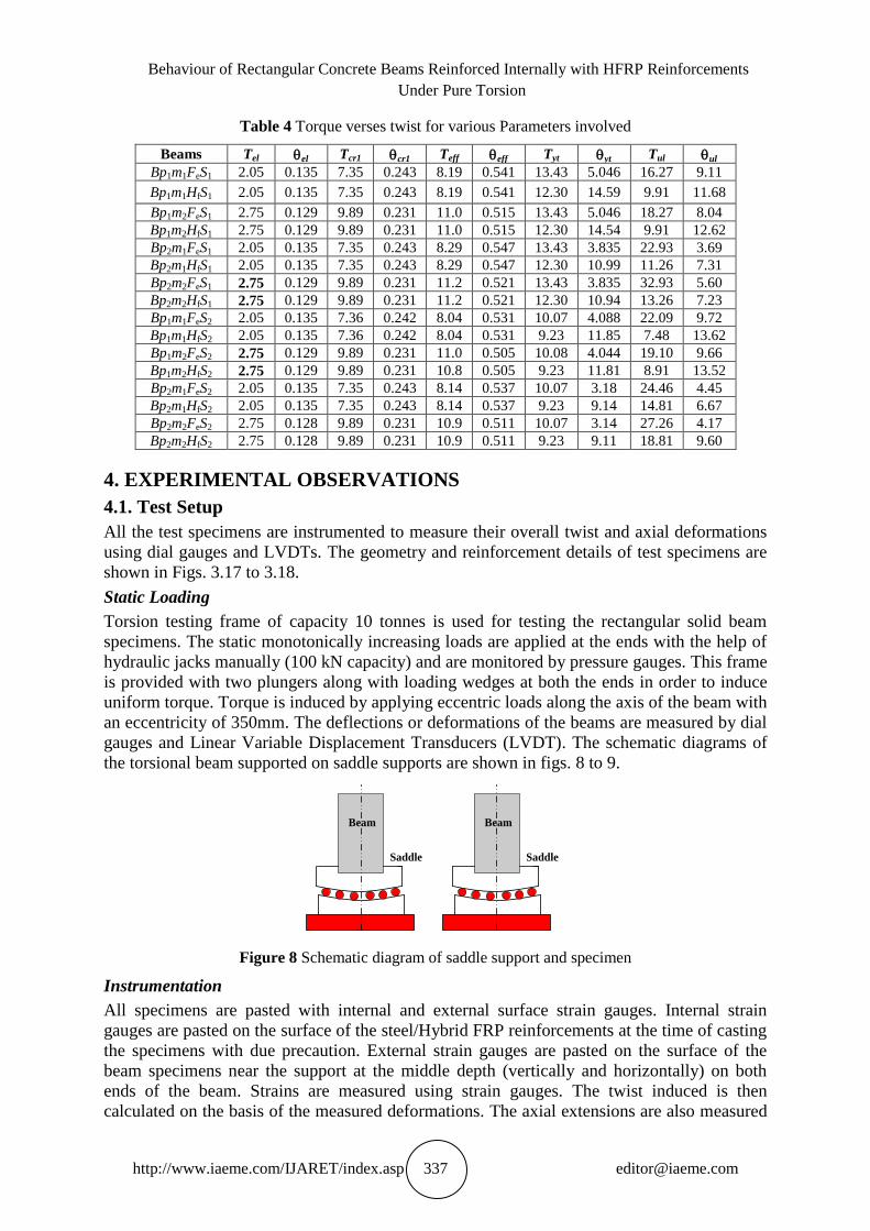
gauges and Linear Variable Displacement Transducers (LVDT). The schematic diagrams of
the torsional beam supported on saddle supports are shown in figs. 8 to 9.
Saddle
Beam
Saddle
Beam
Figure 8 Schematic diagram of saddle support and specimen
Instrumentation
All specimens are pasted with internal and external surface strain gauges. Internal strain
gauges are pasted on the surface of the steel/Hybrid FRP reinforcements at the time of casting
the specimens with due precaution. External strain gauges are pasted on the surface of the
beam specimens near the support at the middle depth (vertically and horizontally) on both
ends of the beam. Strains are measured using strain gauges. The twist induced is then
calculated on the basis of the measured deformations. The axial extensions are also measured
P. Kapildev and G. Kumaran
http://www.iaeme.com/IJARET/index.asp 338 [email protected]
with the help of dial gauges with a least count of 0.01 mm mounted on magnetic base stands
at the end of beam specimens at both the ends. A Data acquisition system is used with a
sampling rate of 50 samples/s to record all LVDT and electrical strain gauge signals. These
electrical signals are converted into strains and are processed with the help of computers. The
load is gradually applied with an increment of 1 kN up to the failure of the beams. The
experimental set up with instrumentations is shown in fig. 3.20. An arial view of the typical
experimental setup with all the instrumentations is shown in fig. 9
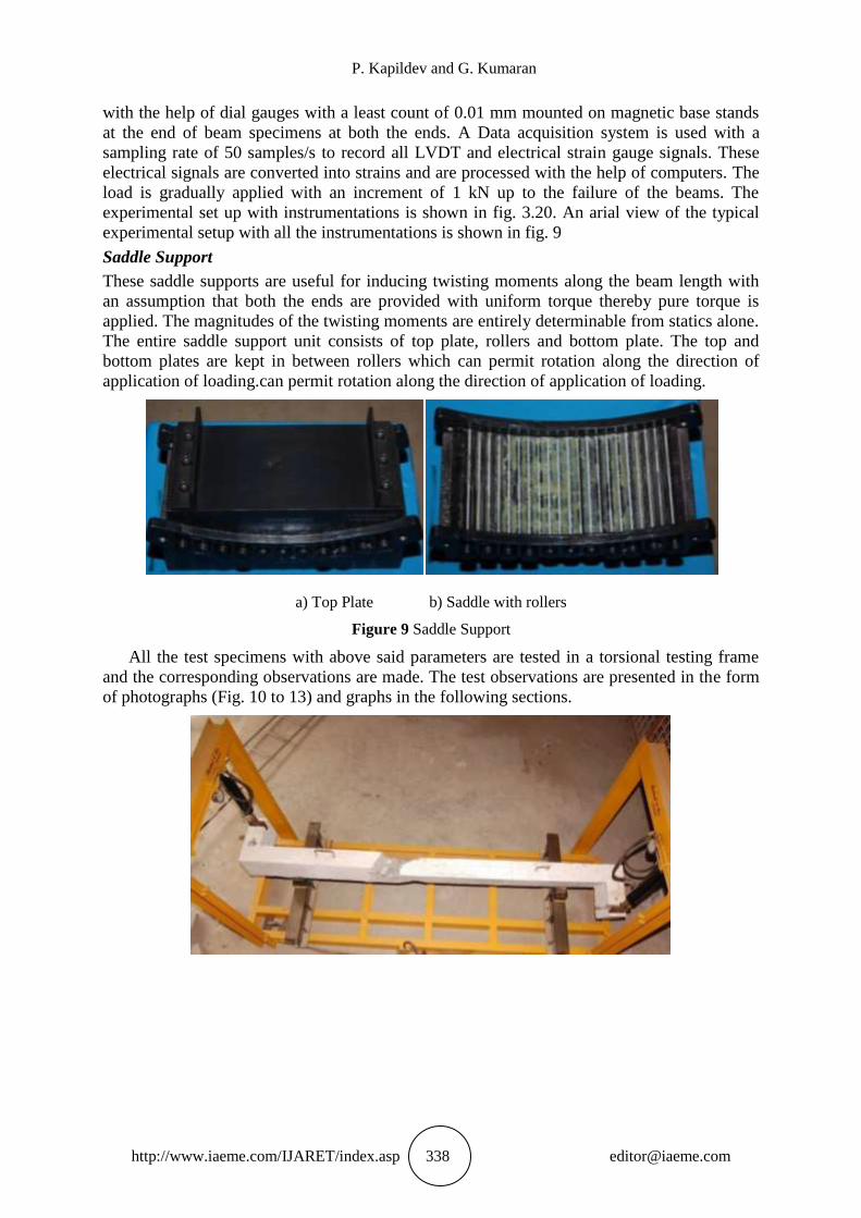
Saddle Support
These saddle supports are useful for inducing twisting moments along the beam length with
an assumption that both the ends are provided with uniform torque thereby pure torque is
applied. The magnitudes of the twisting moments are entirely determinable from statics alone.
The entire saddle support unit consists of top plate, rollers and bottom plate. The top and
bottom plates are kept in between rollers which can permit rotation along the direction of
application of loading.can permit rotation along the direction of application of loading.
a) Top Plate b) Saddle with rollers
Figure 9 Saddle Support
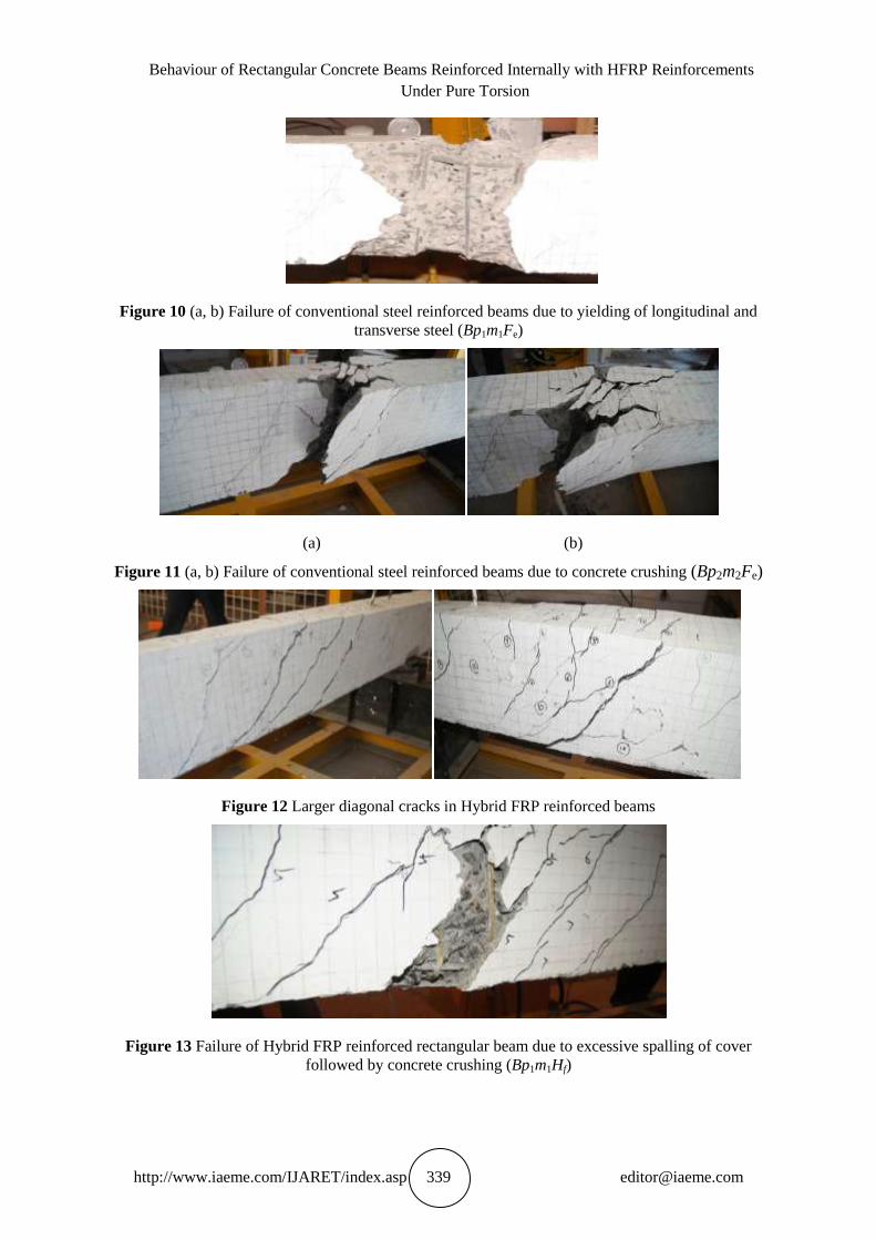
All the test specimens with above said parameters are tested in a torsional testing frame
and the corresponding observations are made. The test observations are presented in the form
of photographs (Fig. 10 to 13) and graphs in the following sections.
Behaviour of Rectangular Concrete Beams Reinforced Internally with HFRP Reinforcements
Under Pure Torsion
http://www.iaeme.com/IJARET/index.asp 339 [email protected]
Figure 10 (a, b) Failure of conventional steel reinforced beams due to yielding of longitudinal and
transverse steel (Bp1m1Fe)
(a) (b)
Figure 11 (a, b) Failure of conventional steel reinforced beams due to concrete crushing (Bp2m2Fe)
Figure 12 Larger diagonal cracks in Hybrid FRP reinforced beams
Figure 13 Failure of Hybrid FRP reinforced rectangular beam due to excessive spalling of cover
followed by concrete crushing (Bp1m1Hf)
P. Kapildev and G. Kumaran
http://www.iaeme.com/IJARET/index.asp 340 [email protected]
5. FINITE ELEMENT MODELLING AND ANALYSIS
The present study, discrete modelling approach is adoted to model the torsional behaviour of
HFRP and Steel Reinforced Concrete (RC) beams. Two different types of element are used to
model each of the reinforced concrete beams; the first one is the Solid65 concrete brick
element which is used for 3D modeling of concrete with reinforcing bars. This element has
eight nodes with three degrees of freedom per nodetranslations in the global x, y and z
directions. The element is capable of handling plastic deformation, cracking in three
orthogonal directions and crushing. Both standard and nonstandard elements can be refined
with additional nodes. These refined elements are of interest for more accurate stress analysis.
The second element type is the Link8 element which was used to model the steel/HFRP
reinforcement. This element is a 3D spar element and it has two nodes with three translational
degrees of freedom per node. This element is also capable of handling plastic deformation and
all are perfectly connected to the nodes of the concrete element. The connectivity between a
concrete node and a reinforcing steel/HFRP node can be achieved by the following method.
5.1. Assumptions Made in this Study
The assumptions considered in this are as follows:
The entire length of the beam is considered for the finite element analysis. The
boundary conditions adopted at the supports to allow rotation in the direction of
application of torque and axial displacement along the length of beam and all other
degrees of freedom restrained and at centre of the beam (symmetry point) all the
displacement degrees of freedom are restrained allowing rotational degrees of freedom
only in order to alleviate the problem of rigid body displacement which can provide a
equilibrium.
Torque is applied by imposing a line load along the width of beam on either side of the
beam end at a equal distance from centre (eccentricity e = 280 mm), obviously this
loading system provide a pure and uniform torque.
HFRP reinforcement are modelled as one dimensional element, only a one
dimensional stressstrain relation is adopted. HFRP reinforcements show their ultimate
tensile strength without exhibiting any material yielding. Unlike steel, the tensile
strength of HFRP reinforcements shown a liner relationship.
The nonlinearity derived from the nonlinear relationships in material models is
considered and the effect of geometric nonlinearity is not considered.
5.2. Material modelling
5.2.1. Concrete
The cracking behaviour in concrete elements needs to be modelled in order to predict
accurately the torquetwist behaviour of reinforced concrete members. At the cracked section
all tension is carried by the reinforcement. Tensile stresses are, however, present in the
concrete between the cracks, since some tension is transferred from steel to concrete through
bond. The magnitude and distribution of bond stresses between the cracks determine the
distribution of tensile stresses in the concrete and the reinforcing steel between the cracks.
Since cracking is the major source of material nonlinearity in the serviceability range of
reinforced concrete structures, realistic cracking models need to be developed. The selection
of a cracking model depends on the purpose of the finite element analysis (Filippou 1990;
Sivagamasundari et al, 2009; Deiveegan et al., 2010; Saravanan et al., 2011). A simplified
averaging procedure is adopted in this study, which assumes that cracks are distributed across
a region of the finite element. In this model, cracked concrete is supposed to remain a
Behaviour of Rectangular Concrete Beams Reinforced Internally with HFRP Reinforcements
Under Pure Torsion
http://www.iaeme.com/IJARET/index.asp 341 [email protected]
continuum and the material properties are then modified to account for the damage induced in
the material. After the first crack has occurred, the concrete becomes orthotropic with the
material axes oriented along the directions of cracking.
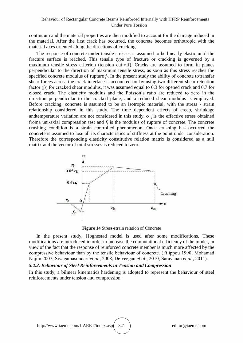
The response of concrete under tensile stresses is assumed to be linearly elastic until the
fracture surface is reached. This tensile type of fracture or cracking is governed by a
maximum tensile stress criterion (tension cutoff). Cracks are assumed to form in planes
perpendicular to the direction of maximum tensile stress, as soon as this stress reaches the
specified concrete modulus of rupture ft. In the present study the ability of concrete to transfer
shear forces across the crack interface is accounted for by using two different shear retention
factor (β) for cracked shear modulus, it was assumed equal to 0.3 for opened crack and 0.7 for
closed crack. The elasticity modulus and the Poisson‘s ratio are reduced to zero in the
direction perpendicular to the cracked plane, and a reduced shear modulus is employed.
Before cracking, concrete is assumed to be an isotropic material, with the stress strain
relationship considered in this study. The time dependent effects of creep, shrinkage
andtemperature variation are not considered in this study. o is the effective stress obtained
froma uniaxial compression test and ft is the modulus of rupture of concrete. The concrete
crushing condition is a strain controlled phenomenon. Once crushing has occurred the
concrete is assumed to lose all its characteristics of stiffness at the point under consideration.
Therefore the corresponding elasticity constitutive relation matrix is considered as a null
matrix and the vector of total stresses is reduced to zero.
Figure 14 Stressstrain relation of Concrete
In the present study, Hognestad model is used after some modifications. These
modifications are introduced in order to increase the computational efficiency of the model, in
view of the fact that the response of reinforced concrete member is much more affected by the
compressive behaviour than by the tensile behaviour of concrete. (Filippou 1990; Mohamad
Najim 2007; Sivagamasundari et al., 2008; Deiveegan et al., 2010; Saravanan et al., 2011).
5.2.2. Behaviour of Steel Reinforcements in Tension and Compression
In this study, a bilinear kinematics hardening is adopted to represent the behaviour of steel
reinforcements under tension and compression.
P. Kapildev and G. Kumaran
http://www.iaeme.com/IJARET/index.asp 342 [email protected]
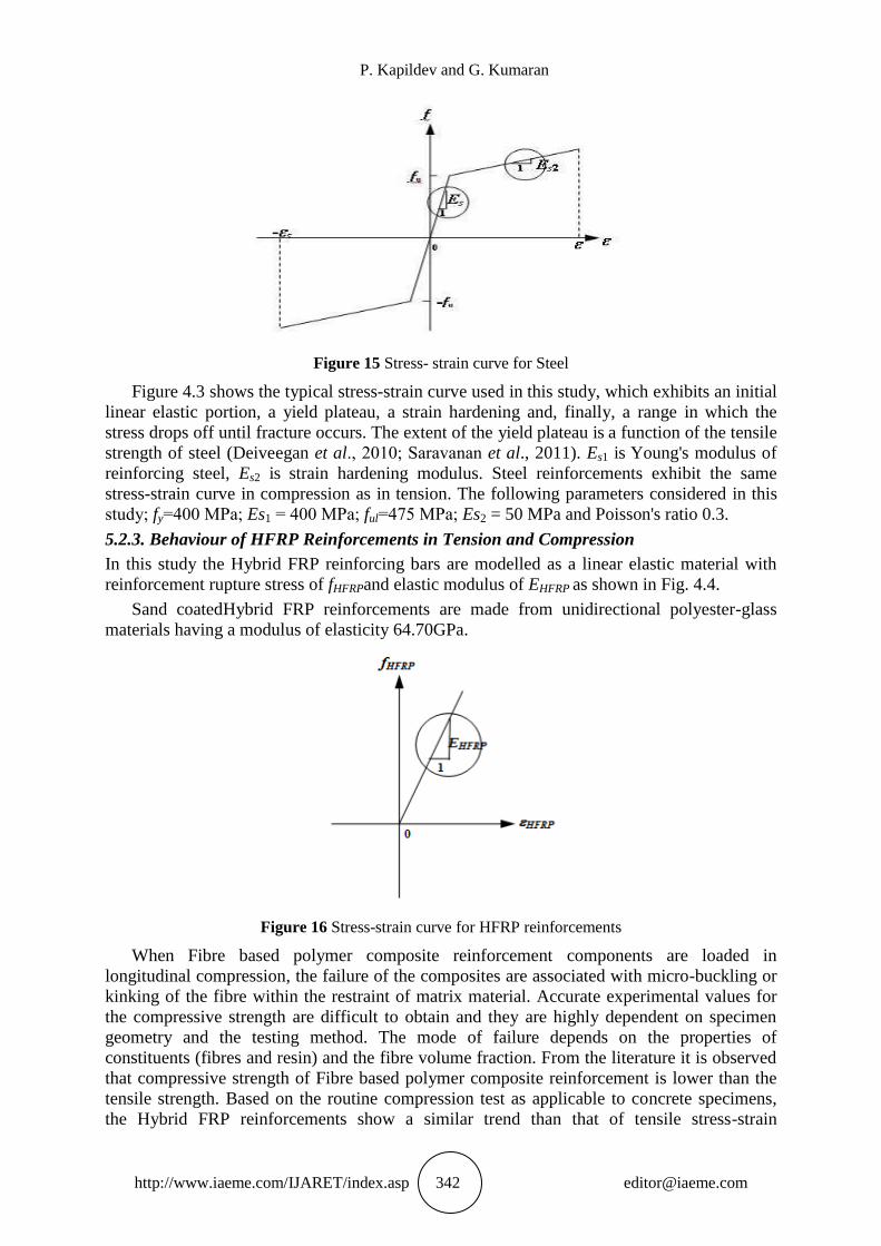
Figure 15 Stress strain curve for Steel
Figure 4.3 shows the typical stressstrain curve used in this study, which exhibits an initial
linear elastic portion, a yield plateau, a strain hardening and, finally, a range in which the
stress drops off until fracture occurs. The extent of the yield plateau is a function of the tensile
strength of steel (Deiveegan et al., 2010; Saravanan et al., 2011). Es1 is Young's modulus of
reinforcing steel, Es2 is strain hardening modulus. Steel reinforcements exhibit the same
stressstrain curve in compression as in tension. The following parameters considered in this
study; fy=400 MPa; Es1 = 400 MPa; ful=475 MPa; Es2 = 50 MPa and Poisson's ratio 0.3.
5.2.3. Behaviour of HFRP Reinforcements in Tension and Compression
In this study the Hybrid FRP reinforcing bars are modelled as a linear elastic material with
reinforcement rupture stress of fHFRPand elastic modulus of EHFRP as shown in Fig. 4.4.
Sand coatedHybrid FRP reinforcements are made from unidirectional polyester-glass
materials having a modulus of elasticity 64.70GPa.
Figure 16 Stress-strain curve for HFRP reinforcements
When Fibre based polymer composite reinforcement components are loaded in
longitudinal compression, the failure of the composites are associated with micro-buckling or
kinking of the fibre within the restraint of matrix material. Accurate experimental values for
the compressive strength are difficult to obtain and they are highly dependent on specimen
geometry and the testing method. The mode of failure depends on the properties of
constituents (fibres and resin) and the fibre volume fraction. From the literature it is observed
that compressive strength of Fibre based polymer composite reinforcement is lower than the
tensile strength. Based on the routine compression test as applicable to concrete specimens,
the Hybrid FRP reinforcements show a similar trend than that of tensile stress-strain
Behaviour of Rectangular Concrete Beams Reinforced Internally with HFRP Reinforcements
Under Pure Torsion
http://www.iaeme.com/IJARET/index.asp 343 [email protected]
relationship. The compressive strength of GFRP reinforcements show 50% reduction than the
tensile strength (Sivagamasundari and Kumaran2008a & 2008b). But due to non availability
of testing procedure, a similar stress-strain behaviour is considered in compression with a
reduced tensile modulus (50% reduction).
5.2.4. Modelling of Slip between the Reinforcements and Concrete
In the simplified analysis of reinforced concrete structures complete compatibility of strains
between concrete and steel is usually assumed, which implies perfect bond. In reality there is
no strain compatibility between reinforcing steel and surrounding concrete near cracks. This
incompatibility and the crack propagation give rise to relative displacements between steel
and concrete, which are known as bond-slip. The bond-slip relationship is established based
on the laboratory experiments, such as the standard pull-out test, the force is applied at the
projecting end of a bar which is embedded in a concrete cylinder. In the finite element model,
when the nodes of the truss element do not need to coincide with the nodes of the concrete
element, then there is a slip. This relative slip between the reinforcement and the concrete is
explicitly taken in this study. Steel/ Hybrid FRP reinforcements exhibit a uniaxial response,
having strength and stiffness characteristics in the bar direction only. The behaviour is treated
incrementally as a one dimensional problem.
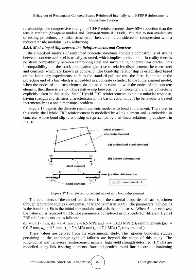
Figure 17 depicts the discrete reinforcements model with bond slip element. Therefore, in
this study, the Hybrid FRP reinforcement is modelled by a link element and is embedded in
concrete, whose bond-slip relationship is represented by a tri-linear relationship as shown in
Fig. 18.
Figure 17 Discrete reinforcement model with bond-slip element
The parameters of the model are derived from the material properties of each specimen
through laboratory studies (Sivagamasundariand Kumaran 2009). The parameters include: ds
is the bond-slip, Eb is the initial slip modulus and ,τ1is the bond stress. When ds1 exceeds ds2,
the value Eb1is replaced by Eb2.The parameters considered in this study for different Hybrid
FRP reinforcements are as follows:
ds1 = 0.017 mm, ds2 = 0.4 mm ,τ1 = 6.5 MPa and τ2 = 13.23 MPa (Hf reinforcements);ds1 =
0.017 mm, ds2 = 0.3 mm , τ1 = 7.6 MPa and τ2 = 17.2 MPa (Fe conventional ).
These values are derived from the experimental study. The rigorous bond-slip studies
pertaining to the anchorage type of failures are beyond the scope of this study. The
longitudinal and transverse reinforcement namely, high yield strength deformed (HYSD) are
modelled using link 8/spring elements. Rate independent multi linear isotropic hardening
P. Kapildev and G. Kumaran
http://www.iaeme.com/IJARET/index.asp 344 [email protected]
option with Von-Mises yield criterion has been used to define the material property of steel
rebar.
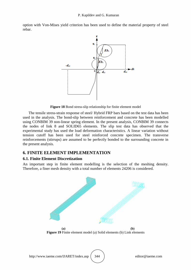
Figure 18 Bond stress-slip relationship for finite element model
The tensile stress-strain response of steel/ Hybrid FRP bars based on the test data has been
used in the analysis. The bond-slip between reinforcement and concrete has been modelled
using CONBIM 39 non-linear spring element. In the present analysis, CONBIM 39 connects
the nodes of link 8 and SOLID65 elements. The slip test data has observed that the
experimental study has used the load deformation characteristics. A linear variation without
tension cutoff has been used for steel reinforced concrete specimen. The transverse
reinforcements (stirrups) are assumed to be perfectly bonded to the surrounding concrete in
the present analysis.
6. FINITE ELEMENT IMPLEMENTATION
6.1. Finite Element Discretization
An important step in finite element modelling is the selection of the meshing density.
Therefore, a finer mesh density with a total number of elements 24206 is considered.
(a) (b)
Figure 19 Finite element model (a) Solid elements (b) Link elements
Behaviour of Rectangular Concrete Beams Reinforced Internally with HFRP Reinforcements
Under Pure Torsion
http://www.iaeme.com/IJARET/index.asp 345 [email protected]
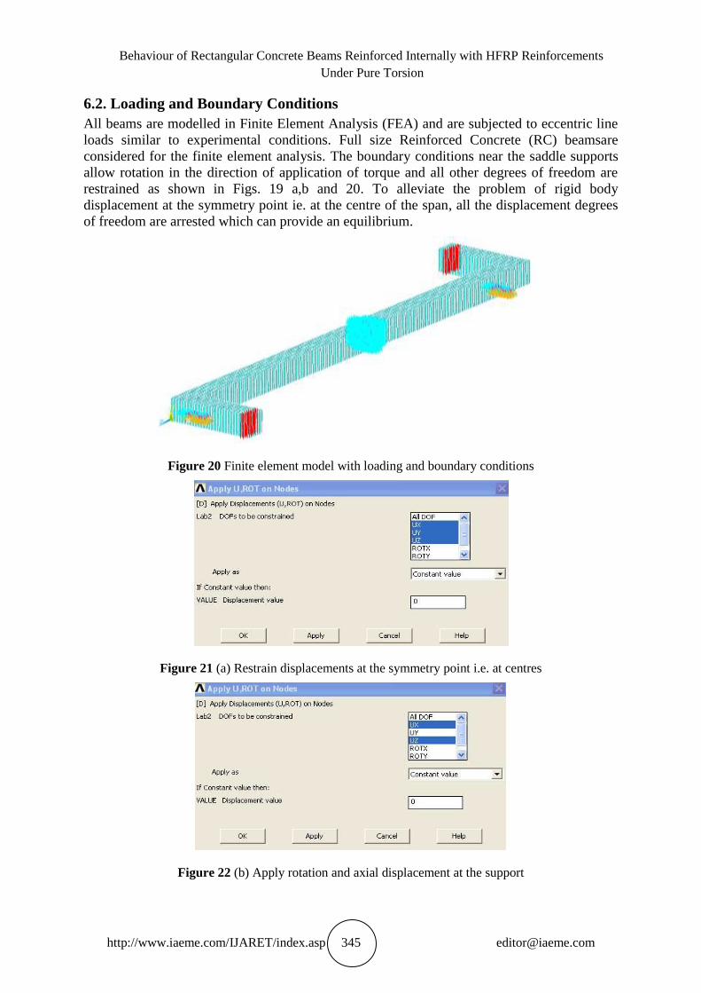
6.2. Loading and Boundary Conditions
All beams are modelled in Finite Element Analysis (FEA) and are subjected to eccentric line
loads similar to experimental conditions. Full size Reinforced Concrete (RC) beamsare
considered for the finite element analysis. The boundary conditions near the saddle supports
allow rotation in the direction of application of torque and all other degrees of freedom are
restrained as shown in Figs. 19 a,b and 20. To alleviate the problem of rigid body
displacement at the symmetry point ie. at the centre of the span, all the displacement degrees
of freedom are arrested which can provide an equilibrium.
Figure 20 Finite element model with loading and boundary conditions
Figure 21 (a) Restrain displacements at the symmetry point i.e. at centres
Figure 22 (b) Apply rotation and axial displacement at the support
P. Kapildev and G. Kumaran
http://www.iaeme.com/IJARET/index.asp 346 [email protected]
Table 5 Material properties of steel/Hybrid FRP reinforcements
Properties Steel(Fe) HFRP (Hf)
Modulus of elasticity Es, (GPa) 210 64.70
Bar size (mm) 12 12
Tensile strength, for main
reinforcement 520 518
Tensile strength, for stirrup
reinforcement 520 147
Compressive strength, fcHFRP(MPa) 660.98 760.05
Poisson‘s ratio 0.3 0.23
Table 6. Material properties for concrete
Properties M30 Grade M60 Grade
Elastic modulus Ec(Pa) 21666 32000
Poisson‘s ratio 0.15 0.2
Ultimate compressive stress fcu(MPa) 42.00 76.00
Tension stiffening coefficient, α 0.6 0.6
Tension stiffening strain coefficient, εm 0.0015 0.0016
6.3. Nonlinear Analysis Procedure
This study uses NewtonRaphson equilibrium iterations for updating the model stiffness.
NewtonRaphson equilibrium iterations provide convergence at the end of each load
increment within tolerance limits. This approach assesses the outofbalance load vector,
which is the difference between the restoring forces (the loads corresponding to the element
stresses) and the applied loads prior to the application of load. Subsequently, the program
carries out a linear solution, using the outofbalance loads, and checks for convergence. If
convergence criteria are not satisfied, the outofbalance load vector is to be re evaluated, the
stiffness matrix is to be updated, and thus a new solution is attained. This iterative procedure
continues until the problem converges. In this study, convergence criteria are based on force
and displacement, and the convergence tolerance limits are initially selected by the program.
It is found that convergence of solutions for the models was difficult to achieve due to the
nonlinear behaviour of reinforced concrete. Therefore, the convergence tolerance limits are
increased to a maximum of 5 times the default tolerance limits (0.5% for force checking and
5% for displacement checking) in order to obtain convergence of the solutions.
For the nonlinear analysis, automatic time stepping is done in the program and it predicts
that it controls load step sizes. Based on the previous solution history and the physics of the
models, if the convergence behaviour is smooth, automatic time stepping will increase the
load increment up to a selected maximum load step size. If the convergence behaviour is
abrupt, automatic time stepping will bisect the load increment until it is equal to a selected
minimum load step size. The maximum and minimum load step sizes are required for the
automatic time stepping. The ultimate torque is the torque at which divergence occurred.
These analyses are carried out with high end system configuration with an integrated
environment for modelling and analysis ( Vasanth 2010 ). The results are also compared with
experimental observations.
Behaviour of Rectangular Concrete Beams Reinforced Internally with HFRP Reinforcements
Under Pure Torsion
http://www.iaeme.com/IJARET/index.asp 347 [email protected]
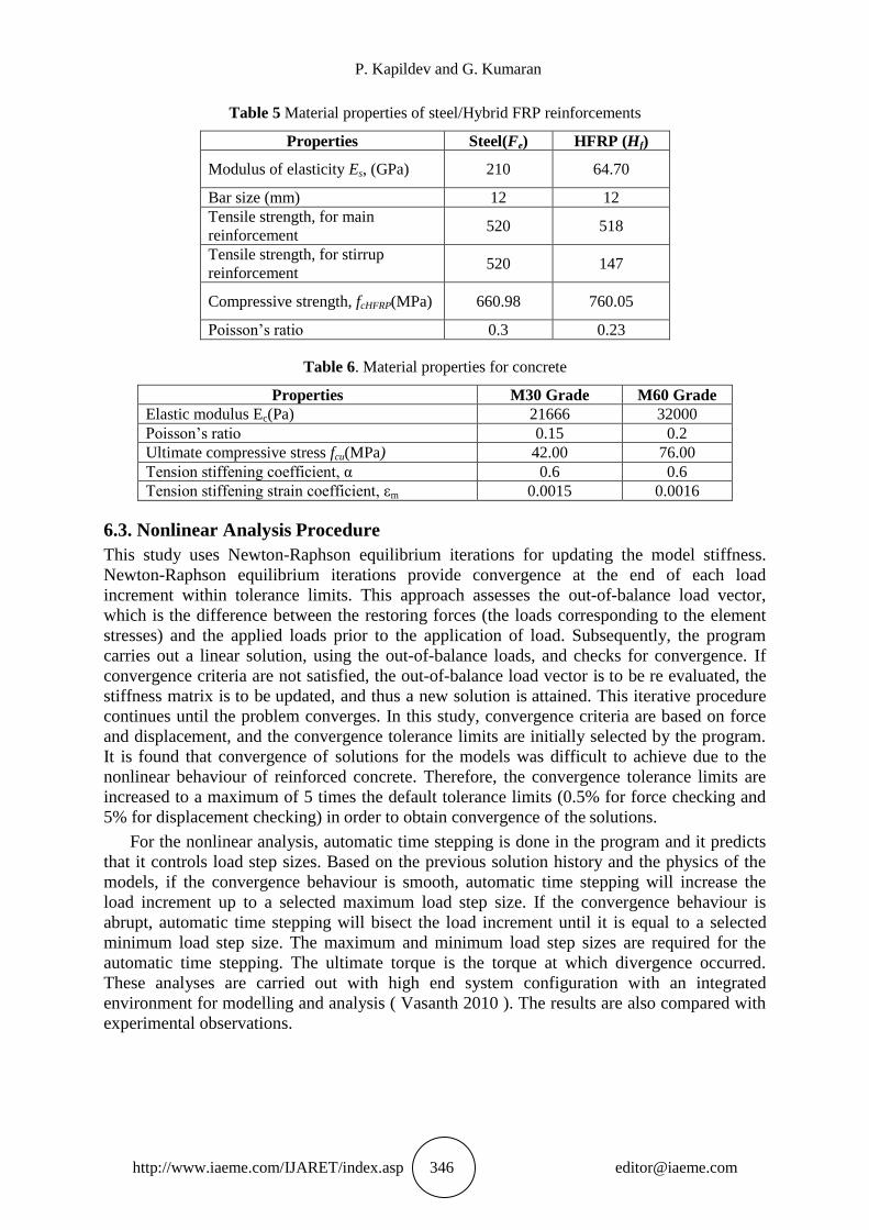
Figure 23 Stress Contours obtained from analysis
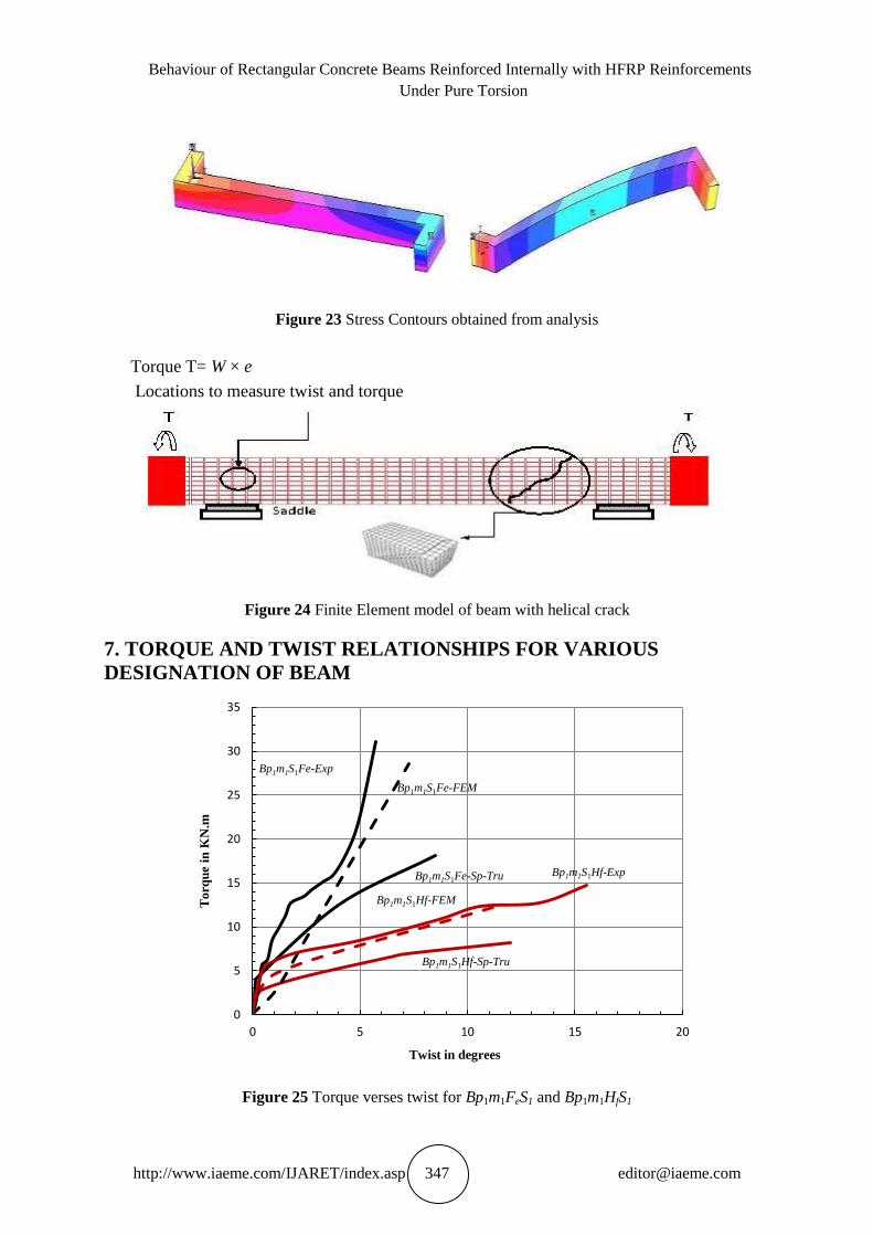
Torque T= W × e
Locations to measure twist and torque
Figure 24 Finite Element model of beam with helical crack
7. TORQUE AND TWIST RELATIONSHIPS FOR VARIOUS
DESIGNATION OF BEAM
Figure 25 Torque verses twist for Bp1m1FeS1 and Bp1m1HfS1
0
5
10
15
20
25
30
35
0 5 10 15 20
Torq
ue
in K
N.m
Twist in degrees
Bp1m1S1Fe-Sp-Tru
Bp1m1S1Fe-FEM
Bp1m1S1Hf-Sp-Tru
Bp1m1S1Hf-FEM
Bp1m1S1Fe-Exp
Bp1m1S1Hf-Exp
P. Kapildev and G. Kumaran
http://www.iaeme.com/IJARET/index.asp 348 [email protected]
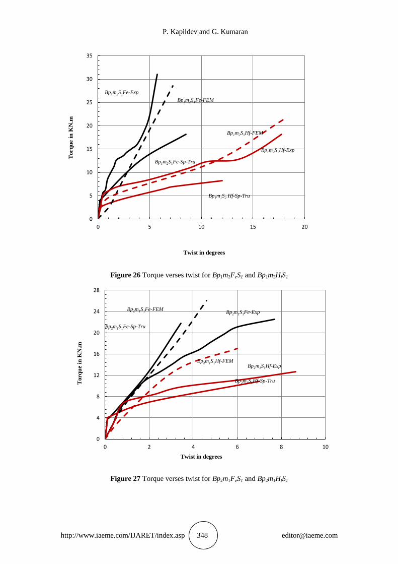
Figure 26 Torque verses twist for Bp1m2FeS1 and Bp1m2HfS1
Figure 27 Torque verses twist for Bp2m1FeS1 and Bp2m1HfS1
0
5
10
15
20
25
30
35
0 5 10 15 20
Torq
ue
in K
N.m
Twist in degrees
Bp1m2S1Fe-Sp-Tru
Bp1m2S1Fe-FEM
Bp1m1S2 Hf-Sp-Tru
Bp1m2S1Hf-FEM
Bp1m2S1Fe-Exp
Bp1m2S1Hf-Exp
0
4
8
12
16
20
24
28
0 2 4 6 8 10
Torq
ue
in K
N.m
Twist in degrees
Bp2m1S1Fe-Sp-Tru
Bp2m1S1Fe-FEM
Bp2m1S1Hf-Sp-Tru
Bp2m1S1Hf-FEM
Bp2m1S1Fe-Exp
Bp2m1S1Hf-Exp
Behaviour of Rectangular Concrete Beams Reinforced Internally with HFRP Reinforcements
Under Pure Torsion
http://www.iaeme.com/IJARET/index.asp 349 [email protected]
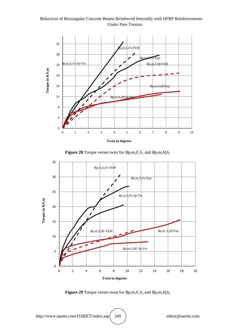
Figure 28 Torque verses twist for Bp2m2FeS1 and Bp2m2HfS1
Figure 29 Torque verses twist for Bp1m1FeS2 and Bp1m1HfS2
0
4
8
12
16
20
24
28
32
0 1 2 3 4 5 6 7 8 9 10
Torq
ue
in K
N.m
Twist in degrees
Bp2m2S1Fe-Sp-Tru
Bp2m2S1Fe-FEM
Bp2m2S1Hf-Sp-Tru
Bp2m2S1Hf-FEM
Bp2m2S1Fe-Exp
Bp2m2S1Hf-Exp
0
5
10
15
20
25
30
35
0 2 4 6 8 10 12 14 16 18 20
Torq
ue
in K
N.m
Twist in degrees
Bp1m1 S2Hf-Exp
Bp1m1S2Fe-Sp-Tru
Bp1m1S2Fe-FEM
Bp1m1S2Hf- Sp-Tru
Bp1m1S2Hf -FEM
Bp1m2 S2Fe-Exp
P. Kapildev and G. Kumaran
http://www.iaeme.com/IJARET/index.asp 350 [email protected]
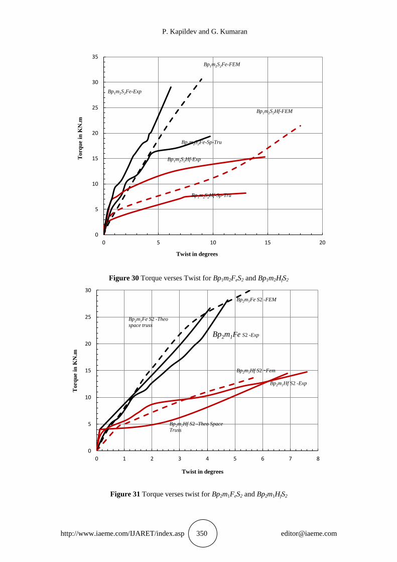
Figure 30 Torque verses Twist for Bp1m2FeS2 and Bp1m2HfS2
Figure 31 Torque verses twist for Bp2m1FeS2 and Bp2m1HfS2
0
5
10
15
20
25
30
35
0 5 10 15 20
Torq
ue
in K
N.m
Twist in degrees
Bp1m2S2Fe-Sp-Tru
Bp1m2S2Fe-FEM
Bp1m2S2Hf-Sp-Tru
Bp1m2S2Hf-FEM
Bp1m2S2Fe-Exp
Bp1m2S2Hf-Exp
0
5
10
15
20
25
30
0 1 2 3 4 5 6 7 8
Torq
ue
in K
N.m
Twist in degrees
Bp2m1Hf S2 -Fem
Bp2m1Fe S2 -FEM
Bp2m1Fe S2 -Exp
Bp2m1Hf S2 -Theo Space
Truss
Bp2m1Fe S2 -Theo
space truss
Bp2m1Hf S2 -Exp
Behaviour of Rectangular Concrete Beams Reinforced Internally with HFRP Reinforcements
Under Pure Torsion
http://www.iaeme.com/IJARET/index.asp 351 [email protected]
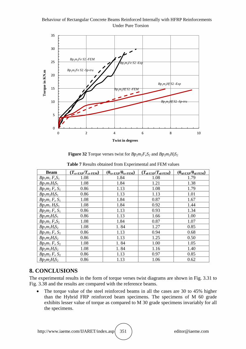
Figure 32 Torque verses twist for Bp2m2FeS2 and Bp2m2HfS2
Table 7 Results obtained from Experimental and FEM values
Beam (Tcr-EXP/Tcr-FEM) (θcr-EXP/θcr-FEM) (Tul-EXP/Tul-FEM) (θul-EXP/θul-FEM)
Bp1m1 FeS1 1.08 1.84 1.08 1.79
Bp1m1HfS1 1.08 1.84 1.21 1.38
Bp1m2 Fe S1 0.86 1.13 1.08 1.79
Bp1m2HfS1 0.86 1.13 1.13 1.01
Bp2m1 Fe S1 1.08 1.84 0.87 1.67
Bp2m1 HfS1 1.08 1.84 0.92 1.44
Bp2m2 Fe S1 0.86 1.13 0.93 1.34
Bp2m2HfS1 0.86 1.13 1.66 1.00
Bp1m1 FeS2 1.08 1.84 0.87 1.07
Bp1m1HfS2 1.08 1. 84 1.27 0.85
Bp1m2 Fe S2 0.86 1.13 0.94 0.68
Bp1m2HfS2 0.86 1.13 1.25 0.50
Bp2m1 Fe S2 1.08 1. 84 1.00 1.05
Bp2m1HfS2 1.08 1. 84 1.16 1.40
Bp2m2 Fe S2 0.86 1.13 0.97 0.85
Bp2m2HfS2 0.86 1.13 1.06 0.62
8. CONCLUSIONS
The experimental results in the form of torque verses twist diagrams are shown in Fig. 3.31 to
Fig. 3.38 and the results are compared with the reference beams.
The torque value of the steel reinforced beams in all the cases are 30 to 45% higher
than the Hybrid FRP reinforced beam specimens. The specimens of M 60 grade
exhibits lesser value of torque as compared to M 30 grade specimens invariably for all
the specimens.
0
5
10
15
20
25
30
35
0 2 4 6 8 10
Torq
ue
in K
N.m
Twist in degrees
Bp2m2Hf S2 -FEM
Bp2m2Fe S2 -FEM
Bp2m2Hf S2 -Sp-tru
Bp2m2Hf S2 -Exp
Bp2m2Fe S2 -Exp
Bp2m2Fe S2 -Sp-tru
P. Kapildev and G. Kumaran
http://www.iaeme.com/IJARET/index.asp 352 [email protected]
The twist value of the Hybrid FRP reinforced beams in all the cases are 20 to 50%
higher than the conventionally reinforced beam specimens. The specimens of M 60
grade exhibits higher twist value of torque as compared to M 30 grade specimens
invariably for all the specimens.
The specimens having the spacing of stirrups 75mm show identical values of torque
and twist value in the ultimate load capacity, both for the steel and Hybrid FRP
reinforced concrete beams, inspite of the concrete grade and the reinforcement ratios.
The increased percentages of (0.86%) reinforcements show better performance in the
load carrying capacity, both for the steel and Hybrid FRP reinforced specimens 10%
to 15%. The same kind of variation has been noticed for the specimens having the
spacing of stirrups 75mm.
The torque-twist behaviour of concrete beams reinforced with HFRP reinforcements
are similar to that of concrete beams reinforced with steel reinforcements until the
formation of the first torsional crack. The value of first crack (Tcr) is insensitive to the
type of reinforcement used. When cracking occurs, there is an increase in twist under
nearly constant torque, due to a drastic loss of torsional stiffness. Beyond this,
however, the strength and behaviour depend on the amount and type of longitudinal
and torsional reinforcement present in the beam.
From the experimental study it is seen that two types of failures are observed for
beams reinforced with steel reinforcements, namely, yielding of longitudinal and
transverse reinforcements and concrete crushing. It is also observed from the present
study that for beams reinforced with conventional steel reinforcements having a
reinforcement ratio lesser than 1% (ie.0.56%) are failed by yielding of longitudinal
and transverse reinforcements before crushing of concrete in compression (Fig.3.26)
but beams with approximately closer to 1% (ie.0.86%) of steel reinforcement ratio are
failed by crushing of concrete in compression before yielding of longitudinal or
transverse reinforcements (Fig.3.27).
Also it is seen that two types of failures are observed for beams (Figs.3.25 to 3.30)
reinforced with Hybrid FRP reinforcements, namely, concrete crushing and rupture of
Hybrid FRP stirrups under tension. Hybrid FRP reinforced concrete beams are failed
due to crushing of concrete followed by rupture of Hybrid FRP stirrups when the
reinforcement ratio lesser than 1% (0.56%). It is probably due to the fact that the
ultimate tensile strains of Hybrid FRP stirrups (generally HFRP pultruded
reinforcements have higher ultimate strains in fact higher than conventional steel, but
HFRP stirrups are not manufactured by pultrusion process and are indeed,
manufactured by vacuum resin bath method which are having lesser ultimate strains
but slightly greater than concrete ultimate strains) and are slightly higher than the
ultimate compressive strains of concrete. Such mode of failure is invariably observed
for all Hybrid FRP reinforced beams with a reinforcement ratio lesser than 1% and
approximately closer to 1%. But none of beams failed due to rupture of Hybrid RFP
reinforcements prior to concrete strain reaches ultimate. It is probably due to the fact
that the ultimate tensile strains of Hybrid FRP reinforcements are greater than the
ultimate compressive strains of concrete.
Torsional strength and angle of twist increases with the increase in grade of concrete
and percentage of longitudinal and transverse reinforcements. But Hybrid FRP
reinforced concrete beams showed higher angle of twist than the conventional
reinforcements. This fact is primarily due to higher tensile strain values for Hybrid
FRP reinforcements than the steel reinforcements.
Behaviour of Rectangular Concrete Beams Reinforced Internally with HFRP Reinforcements
Under Pure Torsion
http://www.iaeme.com/IJARET/index.asp 353 [email protected]
It is also noted that by replacing main and transverse steel reinforcements by an equal
percentage of Hybrid FRP reinforcements, reduced their torsional capacities by 30%
for lower grade concrete but their increase is reduced by 20% for higher grade
concrete and higher percentage of steel.
It is also observed that for steel reinforced concrete beam, the yielding of
reinforcement leads to a larger increase in twist with little change in torque, whereas
Hybrid FRP reinforced beams show no yielding of reinforcements and the twist
continues to increase with the increase in torque, there by exhibiting some ductility
despite the brittle nature of Hybrid FRP reinforcements.
Higher grade of concrete and higher percentage of steel, the torque–twist diagrams
show a increase in torque together with a rapid increase of beam twist. The failures
were characterized by crushing of the concrete at the compressive face, followed by
the yielding of steel stirrups and rupture of Hybrid FRP stirrups. This qualitative
behaviour is observed in Hybrid FRP/steel beams; consequently the overall behavior
of the Hybrid FRP beam is similar to the behavior of conventionally reinforced
concrete beams except that the failure of Hybrid FRP stirrups even after concrete
crushing.
The post peak values of torsional strength of beams have greater influence on the
spacing of stirrups. The minimum spacing of stirrups are arrived based on the Indian
Standards. An examination of the curves reveals that the slope of the curves at the
initial stages of loading is mild for Hybrid FRP reinforced specimens whereas for
conventionally reinforced specimen it is steeper. This is primarily due to lower elastic
modulus than conventional steel reinforcements.
During test all specimens exhibited satisfactory ultimate torsional behaviour, however
the post-peak behaviour differs for Hybrid FRP reinforced beam than the
conventionally reinforced beams.
REFERENCES
[1] ACI 440R96, ―StateoftheArt Report on Fiber Reinforced Plastic (FRP) Reinforcement
for Concrete Structures‖, Reported by ACI Committee 440.
[2] Asghar.M Bhatti and Anan Almughrabi (1996), "Refined Model to Estimate Torsional
Strength of Reinforced Concrete Beams, "ACI Structural Journal, 95(5) pp 614622.
[3] Balajiponraj. G (2011), ―Experimental Study on the Behaviour of Concrete Beams
Reinforced Internally With GFRP Reinforcements under Pure Torsion‖, M.E Thesis,
Department of Civil and Structural Engineering, Annamalai University.
[4] Benmokrane. B, Chaallal. O and Masmoudi. R (1995), flexural response of concrete
Beams Reinforced with FRP Reinforcing Bars, ACI Materials Journal, 91(2), pp 46 55.
[5] Bernardo. F.A et at., (1995), ―Behaviour of Concrete Beams Under Torsion: NSC Plain
and hollow beams‖, Journal of Material and Structures, 41, pp 11431167
[6] ChyuanHwan Jeng, (2010), ―Simple Rational Formulas for cracking Torque and twist of
Reinforced Concrete Members‖, ACI Structural Journal, 107(2), pp 189197.
[7] Collins, M.P., (1972), The TorqueTwist Characteristics of Reinforced Concrete Beams,
Inelasticity and Nonlinearity in Structural Concrete, SM Study No. 8, University of
Waterloo Press, Waterloo, pp 211–232.
P. Kapildev and G. Kumaran
http://www.iaeme.com/IJARET/index.asp 354 [email protected]
[8] Deiveegan. A and Kumaran. G, (2010), ―Reliability Study of Concrete Columns internally
reinforced with Nonmetallic Reinforcements‖, International Journal of Civil and
Structural Engineering, 1(2), pp 270287.
[9] Faza. S.S and Ganga Rao. H.V.S, (1992), bending and bond behavior of concrete beams
reinforced with fibre reinforced plastic rebars, WVDOHRP83 phase 1 report, west
Virginia University, Morgantown, pp 128173.
[10] Filippou. Kwak, H.G. Filip C (1990), finite element analysis of reinforced structures
under monotonic loads, A report on research conducted in Department of Civil
engineering, University of California, Berkeley.
[11] Hsu (1968), T.T.C., Behaviour of Reinforced Concrete Rectangular Members, ACI
Publication SP – 18, ‗Torsion of Structural Concrete‘ American Concrete Institute,
Detroit, pp 261–306.
[12] Hsu, (1968), T.T.C., Ultimate Torque of Reinforced Rectangular Beams, ASCE Journal of
Structural Engineering, 94(1), pp 485–510.
[13] Hsu T.T.C (1984), Torsion of Reinforced Concrete, Van Nostrand Reinhold Publishing
Company, Inc, New York
[14] Hsu T.T.C, Mo YL (1985), Softening of concrete in torsional members—Design
recommendations, Journal of American Concrete Institute Proceedings, 82(4), pp 443–
452.
[15] IS: 10262 (1982), Guide lines for concrete mix design, Bureau of Indian Standards, New
Delhi.
[16] IS: 516 (1959), Code of practiceMethods of test for strength of concrete, Bureau of
Indian standards, New Delhi.
[17] Khaldoun. N et al., (1996), ―Simple Model for Predicting Torsional Strength of
Reinforced and Prestressed Concrete Sections‖, ACI Structural Journal, 93(6),
pp 658666.
[18] Lawrence C. Bank (2006), ―Composite for Construction – Structural Design with FRP
Materials, John Wiley & Sons.
[19] Liang Jenq Leu and Yu Shu Lee, (2000), ― Torsion Design Charts for Reinforced
Concrete Rectangular Members, Journal of Structural Engineering, 126 (2), pp 210218
[20] Lu ıs F. A. Bernardo and Se rgio M. R. Lopes (2007), behaviour of concrete beams
under torsion, Journal of Materials and Structures, 2, pp 3549.
[21] Machida. A (1993), StateoftheArt Report on Continuous Fiber Reinforcing Materials,
Society of Civil Engineers (JSCE), Tokyo, Japan.
[22] MacGregor. J.G and Ghoneim. M.G (1995), ―Design for Torsion‖, ACI Structural Journal,
92(2), pp 21118
[23] Mattock, A.H (1968), ―How to Design for Torsion‖, ACI Publication SP – 18, ‗Torsion of
Structural Concrete‘, American Concrete Institute, March.
[24] Mohammad Najim Mahmood (2007), Nonlinear Analysis of Reinforced Concrete Beams
Under Pure Torsion, Journal of Applied Sciences, 7(22), pp: 35243529.
[25] Muthuramu. K.I, Palanichamy. M.S, Vandhiyan. R (2005), retrofitting of reinforced
concrete rectangular beam using Eglass fibre, Indian Concrete Journal, 1, pp 1520.
[26] Nawy. E.G and Neuwerth. G.E (1997), Fiberglass Reinforced Concrete Slabs and Beams,
Journal of Structural Division, ASCE, 103(2).
[27] Nanni, A (1993), "Flexural Behaviour and Design of RC Members using FRP
Reinforcement, "Journal of the structural Engineering, ASCE, 119(11), pp 33443359.
Behaviour of Rectangular Concrete Beams Reinforced Internally with HFRP Reinforcements
Under Pure Torsion
http://www.iaeme.com/IJARET/index.asp 355 [email protected]
[28] Niema (1993), EI, Fiber Reinforced concrete Beams under Torsion, ACI Structural
Journal, 90(5).
[29] Rahal K.N and Collins. MP (1995), ―Analysis of sections subjected to combined shesr and
torsionA theoretical model‖, ACI Structural Journal, 92(4), pp 459469.
[30] Rasmussen. L.J and Basker. G (1995), Torsion in Reinforced Normal and High Strength
Concrete BeamsPart2: Theory and Design, ACI Structural Journal, 92(1), pp149156.
[31] Saravanan. J and Kumaran. G, 2011), ―Joint shear strength of FRP reinforced concrete
beamcolumn joints‖, Central European Journal of Engineering, 1(1), pp 89102
[32] Salih Elhadi. Moh. Ahmed and ELNiema (1998), Fiber Reinforced Concrete Beams
Subjected to Combined Bending, Shear and Torsion, Sudan Engineering Society Journal,
45(36).
[33] Sivagamasundari, R (2008), ―Analytical and experimental study of one way slabs
reinforced with glass fibre polymer reinforcements‖, Ph.D. Thesis, Department of Civil
and Structural Engineering, Annamalai University.
[34] Trahait. N.S (2005), ―Nonlinear No uniform Torsion‖, ASCE Journal of Structural
Engineering, 131(7), pp 11351142.
[35] Unnikrishna Pillai and Devdas Menon, (2003), ―Reinforced Concrete Design‖, Tata Mc
GrawHill Publishing Company Limited, New Delhi.
[36] Vasanth.V (2010), ―Torsional Behaviour of rectangular concrete beams reinforced with
Glass Fibre Polymer Reinforcements‖, M.E Thesis, Department of Civil and Structural
Engineering, Annamalai University.
[37] Kaushal Kumar, Piyush Gulati, and Akash Gupta, Dinesh Kumar Shukla. (2017). A
Review of Friction Stir Processing of Aluminium Alloys Using Different Types of
Reinforcements. International Journal of Mechanical Engineering and Technology, 8(7),
pp. 1638–1651.
[38] Y.K. Sabapathy, S. Santhanabharathi, M. Bhagirathan, Priyadarshini K.P, Manimanickam
R.M, Durga Abishek Katragadda, Pown Krishnan B, (2018), Behaviour of Concrete Short
Columns with GFRP Reinforcements. International Journal of Civil Engineering and
Technology, 9(1), pp. 455-461
[39] S. Dhipanaravind and R. Sivagamasundari, (2017), Strength Characterization of Glass-
Carbon Hybrid Reinforcements - An Experimental Investigation. International Journal of
Civil Engineering and Technology, 8(2), pp. 338–346
[40] Abdulameer Qasim Hasan, (2019), Analytical and Experimental Response of Single Pile
to Pure Torsion, International Journal of Civil Engineering and Technology, 10(3), pp.
841–851
[41] Nagaraj S B, Chetan S, Shyamaprasad S, Venugopal Nair, (2019), Fatigue Analysis of
Out-Put Shaft Subjected to Pure Torsion, International Journal of Mechanical Engineering
and Technology, 10(4), pp. 9-16