Embed Size (px)
Citation preview
EARTHQUAKE ENGINEERING AND STRUCTURAL DYNAMICS, VOL. 26, 989—1003 (1997)
BEHAVIOUR OF CONTINUOUS PIPELINE SUBJECT TOTRANSVERSE PGD
XUEJIE LIUs AND MICHAEL J. O’ROURKEt*
Department of Civil Engineering Rensselaer Polytechnic Institute, Troy, NY 12180-3590, U.S.A
SUMMARYThe response of buried continuous pipeline to tranverse Permanent Ground Deformation (PGD) has been studied bya number of investigators over the past few years. Herein the numerical results by O’Rourke1 (1988) and Suzuki et al.2 aswell as analytical results by O’Rourke3 are compared. It is shown that the numerical results specifically the peak tensilestrain induced in the pipeline for moderate to large widths of the PGD zone (width *30 m) agree reasonably well, andcompare favourably with existing simplified, closed form, analytical results. However, the peak compressive pipe strainsdiffer as well tensile strains for small widths of the PGD zone (width ¼+10 m). New numerical results are presentedwhich clarify these differences. In addition, an improved analytical model is introduced. Using information from PGDcase histories primarily from Japan, the improved analytical model is shown to match reasonably well with numericalresults. ( 1997 John Wiley & Sons, Ltd.
Earthquake Engng. Struct. Dyn., 26, 989—1003 (1997)
No. of Figures: 15. No. of Tables: 2. No. of References: 8.
KEY WORDS: buried pipeline; permanent ground deformation; pipe strain; transverse PGD
INTRODUCTION
For the seismic analysis and design of buried pipelines, two separate hazards are typically considered. Thewave propagation hazard refers to transient strains induced in a pipeline due to travelling wave effects. ThePermanent Ground Deformation (PGD) hazard refers to pipeline strain due to landslides, ground settlementor liquefaction-induced lateral spreading.
In discussing the PGD hazard, one must distinguish between longitudinal PGD and transverse PGD.Longitudinal PGD refers soil movement parallel to the pipe axis while transverse PGD refers to soilmovement perpendicular to the pipe axis. In general, any arbitrary ground deformation can be decomposedinto a longitudinal and a transverse component. For continuous (e.g. welded steel) pipelines subject tolongitudinal PGD, O’Rourke et al.4 have developed relationships between pipe strain, the amount of groundmovement, and the spatial extent of the PGD zone. Based on these relationships, O’Rourke and O’Rourke5correctly predicted the observed behaviour to six pipelines along Balboa Blvd., which were subject tolongitudinal PGD during the 1994 Northridge earthquake. The analysis indicated that three Grade-B(GR-B) steel pipelines (two large diameter water pipelines with welded slip joints and one gas pipeline withunshielded electric arc joints) would fail while three butt welded gas pipelines would survive, which was, infact, the observed behaviour. Hence existing models for buried pipe response to longitudinal PGD appearadequate. This paper focuses on pipe response to transverse PGD.
* Correspondence to: M. J. O’Rourke, Department of Civil Engineering, Rensselaer Polytechnic Institute, Troy, NY 12180-3590, U.S.A.s Research Assistantt Professor
Contract grant sponsor: NCEER
CCC 0098—8847/97/100989—15$17·50 Received 12 September 1996( 1997 John Wiley & Sons, Ltd. Revised 28 January 1997
When subject to tranverse PGD, a continuous pipeline will stretch and bend as it attempts to accomodatethe tranverse ground movement. The failure mode for the pipe depends then upon the relative amount ofaxial tension (stretching) and flexural (bending) strain. That is, if the axial tension strain is low, the pipe wallmay buckle in compression due to excessive bending. On the other hand, if axial tension is not small, the pipemay rupture in tension due to the combined effects of axial tension and flexure.
Pipeline response to transverse PGD is, in general, a function of the amount of ground movement d, thewidth W of the PGD zone, as well as the pattern of ground deformation. In this paper, continuous pipelineresponse to spatially distributed transverse PGD in which the ground movement towards the centre of thePGD zone is substantially larger than that close to the margins is discussed. Herein the pipeline is assumed tobe contained in a competent soil layer which overrides a liquefied layer below when the PGD is due to lateralspreading. Various analytical idealizations of the spatial distribution (i.e. the pattern of ground deformation)for transverse PGD which have been used in the past are reviewed. Results from existing analytical andnumerical model are compared and differences are noted. New numerical and analytical results are presentedwhich clarify the differences. Finally, the new simplified, closed form, analytical approach proposed herein isshown to work reasonably well for combinations of ground movement d and width ¼ observed in casehistories of transverse PGD in Japan.
IDEALIZATIONS OF SPATIALLY DISTRIBUTED TRANSVERSE PGD
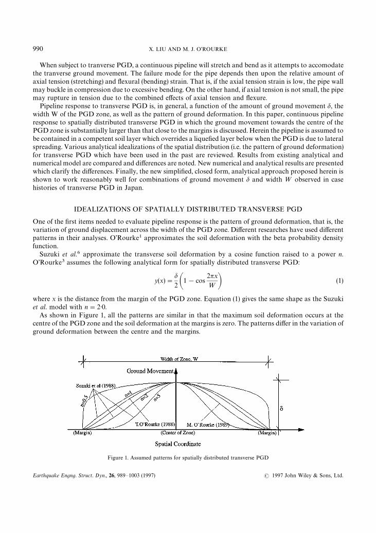
One of the first items needed to evaluate pipeline response is the pattern of ground deformation, that is, thevariation of ground displacement across the width of the PGD zone. Different researches have used differentpatterns in their analyses. O’Rourke1 approximates the soil deformation with the beta probability densityfunction.
Suzuki et al.6 approximate the transverse soil deformation by a cosine function raised to a power n.O’Rourke3 assumes the following analytical form for spatially distributed transverse PGD:
y(x)"d2 A1!cos
2nx
¼ B (1)
where x is the distance from the margin of the PGD zone. Equation (1) gives the same shape as the Suzukiet al. model with n"2·0.
As shown in Figure 1, all the patterns are similar in that the maximum soil deformation occurs at thecentre of the PGD zone and the soil deformation at the margins is zero. The patterns differ in the variation ofground deformation between the centre and the margins.
Figure 1. Assumed patterns for spatially distributed transverse PGD
990 X. LIU AND M. J. O’ROURKE
Earthquake Engng. Struct. Dyn., 26, 989—1003 (1997) ( 1997 John Wiley & Sons, Ltd.
PREVIOUS FINITE ELEMENT RESULTS
The finite element method allows explicit consideration of the non-linear characteristics at the pipe—soilinterface in both the transverse and longitudinal directions as well as non-linear stress—strain relations forpipe material. O’Rourke1 and Suzuki et al.6 have used the finite element approach to evaluate buried piperesponse to spatially distributed transverse PGD. Assumptions and numerical results from each arepresented below.
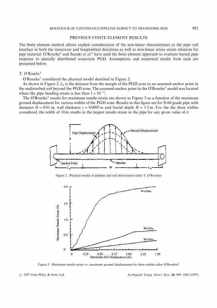
¹. O’Rourke1
O’Rourke1 considered the physical model sketched in Figure 2.As shown in Figure 2, ¸
!is the distance from the margin of the PGD zone to an assumed anchor point in
the undisturbed soil beyond the PGD zone. The assumed anchor point in the O’Rourke1 model was locatedwhere the pipe bending strain is less than 1]10~5.
The O’Rourke1 results for maximum tensile strain are shown in Figure 3 as a function of the maximumground displacement for various widths of the PGD zone. Results in this figure are for X-60 grade pipe withdiameter D"0·61 m, wall thickness t"0·0095 m and burial depth H"1·5 m. For the the three widthsconsidered, the width of 10m results in the largest tensile strain in the pipe for any given value of d.
Figure 2. Physical model of pipeline and soil deformation (after T. O’Rourke)
Figure 3. Maximum tensile strain vs. maximum ground displacement for three widths (after O’Rourke)1
BEHAVIOUR OF CONTINUOUS PIPELINE SUBJECT TO TRANSVERSE PGD 991
( 1997 John Wiley & Sons, Ltd. Earthquake Engng. Struct. Dyn., 26, 989—1003 (1997)
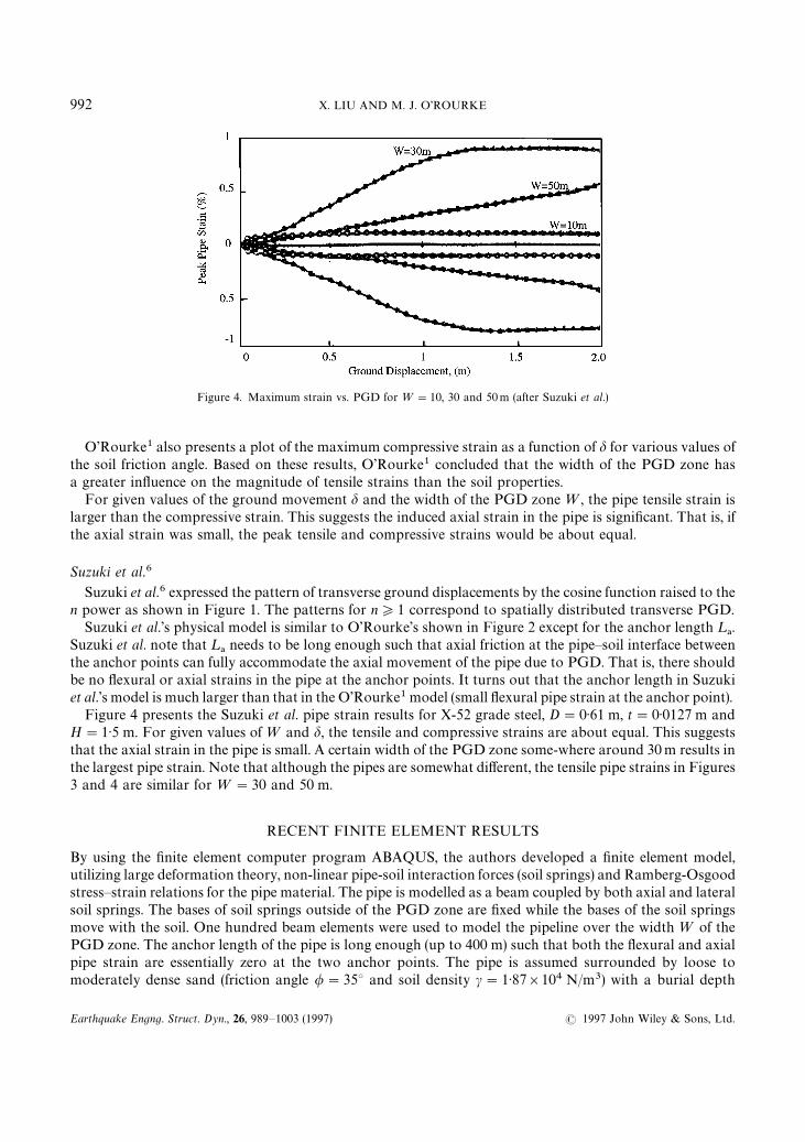
Figure 4. Maximum strain vs. PGD for ¼"10, 30 and 50m (after Suzuki et al.)
O’Rourke1 also presents a plot of the maximum compressive strain as a function of d for various values ofthe soil friction angle. Based on these results, O’Rourke1 concluded that the width of the PGD zone hasa greater influence on the magnitude of tensile strains than the soil properties.
For given values of the ground movement d and the width of the PGD zone ¼, the pipe tensile strain islarger than the compressive strain. This suggests the induced axial strain in the pipe is significant. That is, ifthe axial strain was small, the peak tensile and compressive strains would be about equal.
Suzuki et al.6
Suzuki et al.6 expressed the pattern of transverse ground displacements by the cosine function raised to then power as shown in Figure 1. The patterns for n*1 correspond to spatially distributed transverse PGD.
Suzuki et al.’s physical model is similar to O’Rourke’s shown in Figure 2 except for the anchor length ¸!.
Suzuki et al. note that ¸!needs to be long enough such that axial friction at the pipe—soil interface between
the anchor points can fully accommodate the axial movement of the pipe due to PGD. That is, there shouldbe no flexural or axial strains in the pipe at the anchor points. It turns out that the anchor length in Suzukiet al.’s model is much larger than that in the O’Rourke1 model (small flexural pipe strain at the anchor point).
Figure 4 presents the Suzuki et al. pipe strain results for X-52 grade steel, D"0·61 m, t"0·0127 m andH"1·5 m. For given values of ¼ and d, the tensile and compressive strains are about equal. This suggeststhat the axial strain in the pipe is small. A certain width of the PGD zone some-where around 30m results inthe largest pipe strain. Note that although the pipes are somewhat different, the tensile pipe strains in Figures3 and 4 are similar for ¼"30 and 50 m.
RECENT FINITE ELEMENT RESULTS
By using the finite element computer program ABAQUS, the authors developed a finite element model,utilizing large deformation theory, non-linear pipe-soil interaction forces (soil springs) and Ramberg-Osgoodstress—strain relations for the pipe material. The pipe is modelled as a beam coupled by both axial and lateralsoil springs. The bases of soil springs outside of the PGD zone are fixed while the bases of the soil springsmove with the soil. One hundred beam elements were used to model the pipeline over the width ¼ of thePGD zone. The anchor length of the pipe is long enough (up to 400 m) such that both the flexural and axialpipe strain are essentially zero at the two anchor points. The pipe is assumed surrounded by loose tomoderately dense sand (friction angle /"35° and soil density c"1·87]104 N/m3) with a burial depth
992 X. LIU AND M. J. O’ROURKE
Earthquake Engng. Struct. Dyn., 26, 989—1003 (1997) ( 1997 John Wiley & Sons, Ltd.
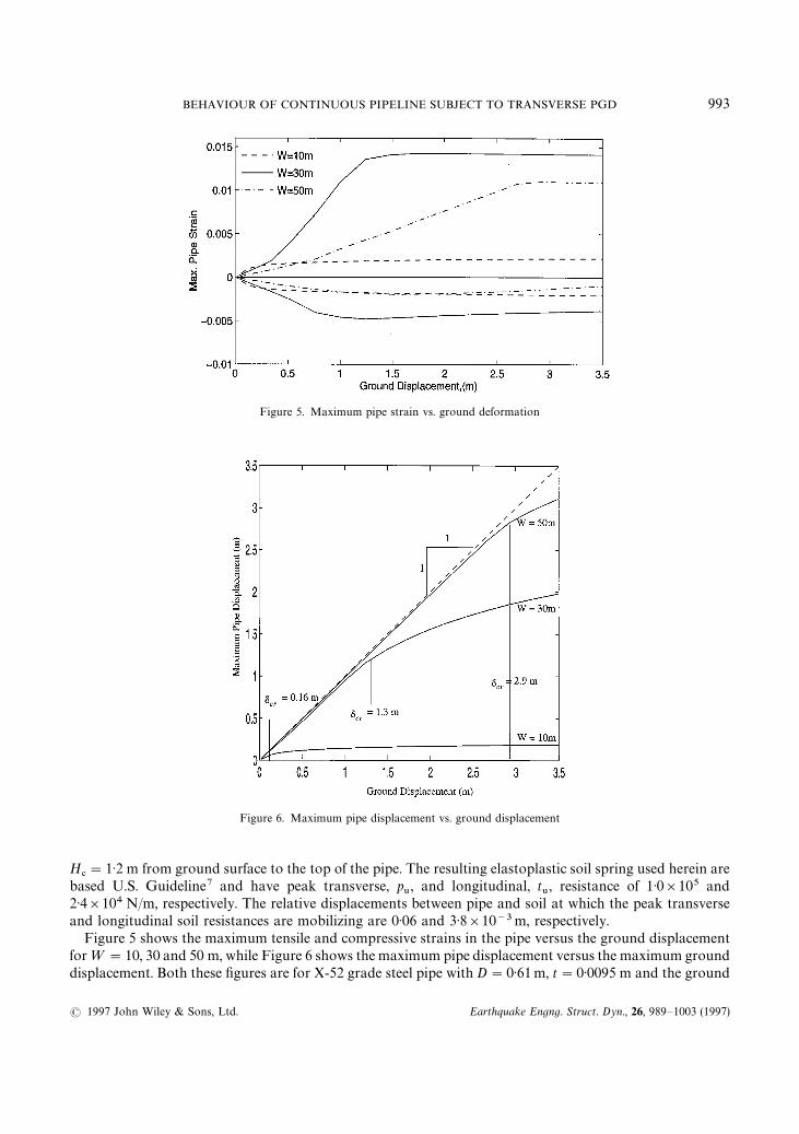
Figure 5. Maximum pipe strain vs. ground deformation
Figure 6. Maximum pipe displacement vs. ground displacement
H#"1·2 m from ground surface to the top of the pipe. The resulting elastoplastic soil spring used herein are
based U.S. Guideline7 and have peak transverse, p6, and longitudinal, t
6, resistance of 1·0]105 and
2·4]104 N/m, respectively. The relative displacements between pipe and soil at which the peak transverseand longitudinal soil resistances are mobilizing are 0·06 and 3·8]10~3m, respectively.
Figure 5 shows the maximum tensile and compressive strains in the pipe versus the ground displacementfor ¼"10, 30 and 50 m, while Figure 6 shows the maximum pipe displacement versus the maximum grounddisplacement. Both these figures are for X-52 grade steel pipe with D"0·61m, t"0·0095 m and the ground
BEHAVIOUR OF CONTINUOUS PIPELINE SUBJECT TO TRANSVERSE PGD 993
( 1997 John Wiley & Sons, Ltd. Earthquake Engng. Struct. Dyn., 26, 989—1003 (1997)
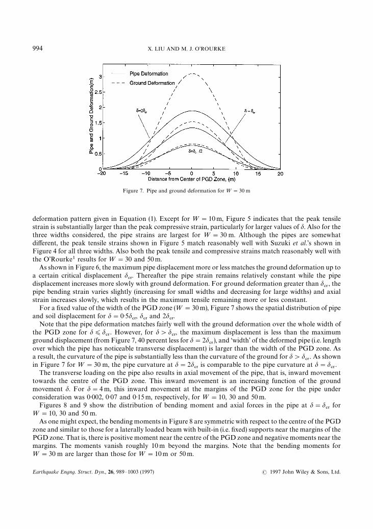
Figure 7. Pipe and ground deformation for ¼"30 m
deformation pattern given in Equation (1). Except for ¼"10m, Figure 5 indicates that the peak tensilestrain is substantially larger than the peak compressive strain, particularly for larger values of d. Also for thethree widths considered, the pipe strains are largest for ¼"30 m. Although the pipes are somewhatdifferent, the peak tensile strains shown in Figure 5 match reasonably well with Suzuki et al.’s shown inFigure 4 for all three widths. Also both the peak tensile and compressive strains match reasonably well withthe O’Rourke1 results for ¼"30 and 50m.
As shown in Figure 6, the maximum pipe displacement more or less matches the ground deformation up toa certain critical displacement d
#3. Thereafter the pipe strain remains relatively constant while the pipe
displacement increases more slowly with ground deformation. For ground deformation greater than d#3
, thepipe bending strain varies slightly (increasing for small widths and decreasing for large widths) and axialstrain increases slowly, which results in the maximum tensile remaining more or less constant.
For a fixed value of the width of the PGD zone (¼"30m), Figure 7 shows the spatial distribution of pipeand soil displacement for d"0·5d
#3, d
#3and 2d
#3.
Note that the pipe deformation matches fairly well with the ground deformation over the whole width ofthe PGD zone for d)d
#3. However, for d'd
#3, the maximum displacement is less than the maximum
ground displacement (from Figure 7, 40 percent less for d"2d#3
), and ‘width’ of the deformed pipe (i.e. lengthover which the pipe has noticeable transverse displacement) is larger than the width of the PGD zone. Asa result, the curvature of the pipe is substantially less than the curvature of the ground for d'd
#3. As shown
in Figure 7 for ¼"30 m, the pipe curvature at d"2d#3
is comparable to the pipe curvature at d"d#3
.The transverse loading on the pipe also results in axial movement of the pipe, that is, inward movement
towards the centre of the PGD zone. This inward movement is an increasing function of the groundmovement d. For d"4 m, this inward movement at the margins of the PGD zone for the pipe underconsideration was 0·002, 0·07 and 0·15m, respectively, for ¼"10, 30 and 50m.
Figures 8 and 9 show the distribution of bending moment and axial forces in the pipe at d"d#3
for¼"10, 30 and 50 m.
As one might expect, the bending moments in Figure 8 are symmetric with respect to the centre of the PGDzone and similar to those for a laterally loaded beam with built-in (i.e. fixed) supports near the margins of thePGD zone. That is, there is positive moment near the centre of the PGD zone and negative moments near themargins. The moments vanish roughly 10 m beyond the margins. Note that the bending moments for¼"30 m are larger than those for ¼"10m or 50m.
994 X. LIU AND M. J. O’ROURKE
Earthquake Engng. Struct. Dyn., 26, 989—1003 (1997) ( 1997 John Wiley & Sons, Ltd.
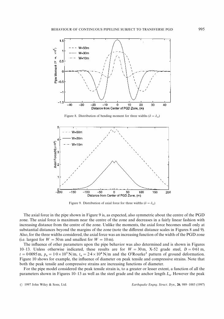
Figure 8. Distribution of bending moment for three widths (d"d#3)
Figure 9. Distribution of axial force for three widths (d"d#3)
The axial force in the pipe shown in Figure 9 is, as expected, also symmetric about the centre of the PGDzone. The axial force is maximum near the centre of the zone and decreases in a fairly linear fashion withincreasing distance from the centre of the zone. Unlike the moments, the axial force becomes small only atsubstantial distances beyond the margins of the zone (note the different distance scales in Figures 8 and 9).Also, for the three widths considered, the axial force was an increasing function of the width of the PGD zone(i.e. largest for ¼"50m and smallest for ¼"10m).
The influence of other parameters upon the pipe behavior was also determined and is shown in Figures10—13. Unless otherwise indicated, these results are for ¼"30m, X-52 grade steel, D"0·61 m,t"0·0095m, p
6"1·0]105N/m, t
6"2·4]104N/m and the O’Rourke3 pattern of ground deformation.
Figure 10 shows for example, the influence of diameter on peak tensile and compressive strains. Note thatboth the peak tensile and compressive strains are increasing functions of diameter.
For the pipe model considered the peak tensile strain is, to a greater or lesser extent, a function of all theparameters shown in Figures 10—13 as well as the steel grade and the anchor length ¸
!. However the peak
BEHAVIOUR OF CONTINUOUS PIPELINE SUBJECT TO TRANSVERSE PGD 995
( 1997 John Wiley & Sons, Ltd. Earthquake Engng. Struct. Dyn., 26, 989—1003 (1997)
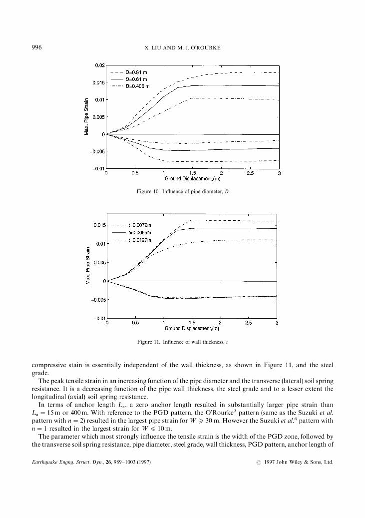
Figure 10. Influence of pipe diameter, D
Figure 11. Influence of wall thickness, t
compressive stain is essentially independent of the wall thickness, as shown in Figure 11, and the steelgrade.
The peak tensile strain in an increasing function of the pipe diameter and the transverse (lateral) soil springresistance. It is a decreasing function of the pipe wall thickness, the steel grade and to a lesser extent thelongitudinal (axial) soil spring resistance.
In terms of anchor length ¸!, a zero anchor length resulted in substantially larger pipe strain than
¸!"15 m or 400m. With reference to the PGD pattern, the O’Rourke3 pattern (same as the Suzuki et al.
pattern with n"2) resulted in the largest pipe strain for ¼*30 m. However the Suzuki et al.6 pattern withn"1 resulted in the largest strain for ¼)10m.
The parameter which most strongly influence the tensile strain is the width of the PGD zone, followed bythe transverse soil spring resistance, pipe diameter, steel grade, wall thickness, PGD pattern, anchor length of
996 X. LIU AND M. J. O’ROURKE
Earthquake Engng. Struct. Dyn., 26, 989—1003 (1997) ( 1997 John Wiley & Sons, Ltd.
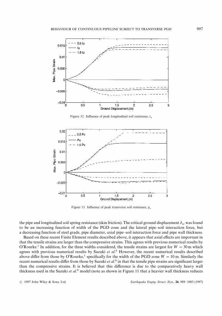
Figure 12. Influence of peak longitudinal soil resistance, t6
Figure 13. Influence of peak transverse soil resistance, p6
the pipe and longitudinal soil spring resistance (skin friction). The critical ground displacement d#3
was foundto be an increasing function of width of the PGD zone and the lateral pipe—soil interaction force, buta decreasing function of steel grade, pipe diameter, axial pipe—soil interaction force and pipe wall thickness.
Based on these recent Finite Element results described above, it appears that axial effects are important inthat the tensile strains are larger than the compressive strains. This agrees with previous numerical results byO’Rourke.1 In addition, for the three widths considered, the tensile strains are largest for ¼"30 m whichagrees with previous numerical results by Suzuki et al.6 However, the recent numerical results describedabove differ from those by O’Rourke,1 specifically for the width of the PGD zone ¼"10 m. Similarly therecent numerical results differ from those by Suzuki et al.6 in that the tensile pipe strains are significant largerthan the compressive strains. It is believed that this difference is due to the comparatively heavy wallthickness used in the Suzuki et al.6 model (note as shown in Figure 11 that a heavier wall thickness reduces
BEHAVIOUR OF CONTINUOUS PIPELINE SUBJECT TO TRANSVERSE PGD 997
( 1997 John Wiley & Sons, Ltd. Earthquake Engng. Struct. Dyn., 26, 989—1003 (1997)
the peak tensile strain but essentially has no effect on the peak compressive strain) in combination witha relatively weak longitudinal soil spring.
PREVIOUS ANALYTICAL APPROACH
O’Rourke3 developed a simple analytical model for pipeline response to spatially distributed transversePGD. He considered two types of response. For a wide width of the PGD zone, the pipeline is relativelyflexible and its lateral displacement is assumed to closely match that of the soil. For this case the pipe strainwas assumed to be mainly due to the ground curvature (i.e. displacement controlled). For a narrow width, thepipeline is relatively stiff and the pipe lateral displacement is substantially less than that of the soil. In thiscase, the pipe strain was assumed to be due to loading at the soil—pipe interface (i.e. loading controlled).
For the wide PGD width/flexible pipe case, the pipe is assumed to match the soil deformation given byEquation (1). The maximum bending strain, e
", in the pipe, is given by
e""$
n2dD
¼2(2)
In this simple model, the axial tensile strain is based solely upon the arclength of the pipe between the PGDzone margins. Assuming the pipe matches exactly the lateral soil displacement, the average axial tensilestrain, e
!, is approximated by
e!"A
n2B
2
Ad¼B
2(3)
For the narrow width/stiff pipe case, the pipe is modeled as a beam, built-in at each margin (i.e. fixed—fixedbeam), subject to the maximum lateral force per unit length p
6at the soil—pipe interface. For this case the
axial tension due to arclength effects is small and neglected. Hence, the maximum strain in the pipe is givenby
e""$
p6¼2
3nEtD2(4)
Note that O’Rourke3 assumes that the pipe is fixed at the margins and hence neglects any inward (i.e. axial)movement of pipe at the margin of PGD zone. As a result, equation (3) overestimates the axial strain in thepipe, as will be shown later.
RECENT ANALYTICAL APPROACH
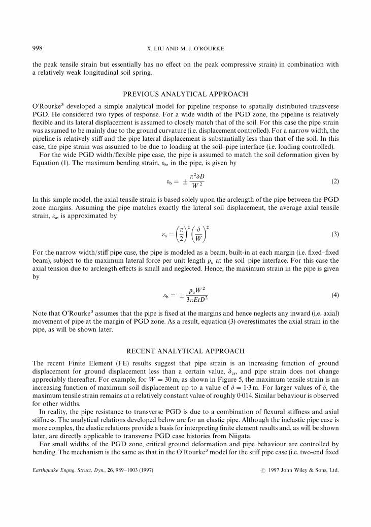
The recent Finite Element (FE) results suggest that pipe strain is an increasing function of grounddisplacement for ground displacement less than a certain value, d
#3, and pipe strain does not change
appreciably thereafter. For example, for ¼"30m, as shown in Figure 5, the maximum tensile strain is anincreasing function of maximum soil displacement up to a value of d"1·3m. For larger values of d, themaximum tensile strain remains at a relatively constant value of roughly 0·014. Similar behaviour is observedfor other widths.
In reality, the pipe resistance to transverse PGD is due to a combination of flexural stiffness and axialstiffness. The analytical relations developed below are for an elastic pipe. Although the inelastic pipe case ismore complex, the elastic relations provide a basis for interpreting finite element results and, as will be shownlater, are directly applicable to transverse PGD case histories from Niigata.
For small widths of the PGD zone, critical ground deformation and pipe behaviour are controlled bybending. The mechanism is the same as that in the O’Rourke3 model for the stiff pipe case (i.e. two-end fixed
998 X. LIU AND M. J. O’ROURKE
Earthquake Engng. Struct. Dyn., 26, 989—1003 (1997) ( 1997 John Wiley & Sons, Ltd.
beam with constant distributed load). The critical ground deformation is given by
d#3-bending"
p6¼4
384EI(5)
For very larger widths of the PGD zone, the pipe behaves like a flexible cable (i.e. negligible flexural stiffness).For this case, the critical displacement is controlled primarily by the axial force. For parabolic cable, therelation between the axial force ¹ at the ends and the maximum lateral deformation (or sag) d is given by
¹"
p6¼2
8d(6)
As shown in Figure 7, the ground displacement is larger than the pipe displacement in the middle region ofthe PGD zone (assumed herein to be ¼/2), over which the maximum transverse resistance per unit length, p
6,
at the pipe—soil interface (i.e. the distributed load) is imposed. Taking the ‘sag’ over this middle region to bed/2, the interrelationship between the tensile force, ¹, and ground displacement, d, is given by
¹"nDtp"p6(¼/2)2
8(d/2)"
p6¼2
16d(7)
where p is the axial stress in the pipe (assumed to be constant within the PGD zone).Inward movement of the pipe occurs at the margin of the PGD zone due to this axial force. Assuming
a constant longitudinal friction force, t6, beyond the margins, the pipe inward movement at each margin is
**/8!3$
"
nDtp2
2Et6
(8)
The total axial elongation of the pipe within the PGD zone is approximated by the average axial strain givenby equation (3) (i.e. arclength effect) times the width ¼. This elongation is due to stretching within the zone(p¼/E) and inward movement at the margins from equation (8):
n2d2
4¼"
p¼E
#2nDtp2
2Et6
(9)
The critical ground deformation, dcr-axial for ‘cable-like’ behaviour and the corresponding axial pipe stress, p,can be calculated by simultaneous solution of equations (7) and (9). These values are presented in Table I forthree values of the width ¼ and the standard properties mentioned previously (i.e. D"0.61m, t"0·0095m,p6"1·0]105N/m, t
6"2·4]104N/m). Note that the critical ground deformation is controlled by axial
force for this case, and that the maximum axial stress at d"d#3
in an increasing function of width of the PGDzone.
For any arbitrary width of the PGD zone, somewhat between small and very large, resistance is providedby both flexural (beam) and axial (cable) effects. Considering these elements to be acting in parallel,
d#3"
1
1
dcr-bending
#
1
dcr-axial
(10)
Table II lists the resulting critical displacements of an elastic pipe (D"0·61m, t"0·0095m, etc.) for ¼"10,30 and 50m along with the corresponding elastic finite element results. For ¼"30 and 50 m, the criticaldisplacement from equation (10) matches that from the elastic finite element model. However, for ¼"10m,the critical displacement from equation (10) is an order of magnitude less than that from the elastic finiteelement model. This is due, in part, to the assumption of a constant transverse load p
6on the pipe for bending
BEHAVIOUR OF CONTINUOUS PIPELINE SUBJECT TO TRANSVERSE PGD 999
( 1997 John Wiley & Sons, Ltd. Earthquake Engng. Struct. Dyn., 26, 989—1003 (1997)
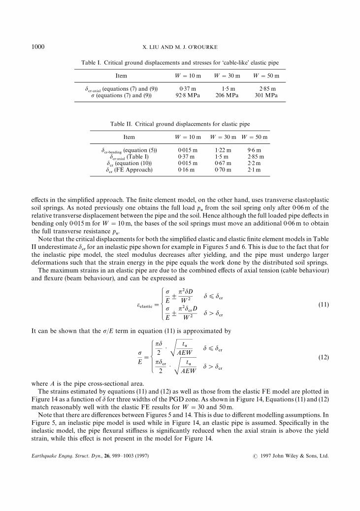
Table I. Critical ground displacements and stresses for ‘cable-like’ elastic pipe
Item ¼"10 m ¼"30 m ¼"50 m
d#3-axial (equations (7) and (9)) 0·37 m 1·5 m 2·85 mp (equations (7) and (9)) 92·8 MPa 206 MPa 301 MPa
Table II. Critical ground displacements for elastic pipe
Item ¼"10 m ¼"30 m ¼"50 m
dcr-bending (equation (5)) 0·015 m 1·22 m 9·6 mdcr-axial (Table I) 0·37 m 1·5 m 2·85 m
d#3
(equation (10)) 0·015 m 0·67 m 2·2 md#3
(FE Approach) 0·16 m 0·70 m 2·1 m
effects in the simplified approach. The finite element model, on the other hand, uses transverse elastoplasticsoil springs. As noted previously one obtains the full load p
6from the soil spring only after 0·06m of the
relative transverse displacement between the pipe and the soil. Hence although the full loaded pipe deflects inbending only 0·015m for ¼"10 m, the bases of the soil springs must move an additional 0·06m to obtainthe full transverse resistance p
6.
Note that the critical displacements for both the simplified elastic and elastic finite element models in TableII underestimate d
#3for an inelastic pipe shown for example in Figures 5 and 6. This is due to the fact that for
the inelastic pipe model, the steel modulus decreases after yielding, and the pipe must undergo largerdeformations such that the strain energy in the pipe equals the work done by the distributed soil springs.
The maximum strains in an elastic pipe are due to the combined effects of axial tension (cable behaviour)and flexure (beam behaviour), and can be expressed as
e%-!45*#
"
pE$
n2dD
¼2d)d
#3
pE$
n2d#3
D
¼2d'd
#3
(11)
It can be shown that the p/E term in equation (11) is approximated by
pE"
nd2
· St6
AE¼
d)d#3
nd#3
2· S
t6
AE¼
d'd#3
(12)
where A is the pipe cross-sectional area.The strains estimated by equations (11) and (12) as well as those from the elastic FE model are plotted in
Figure 14 as a function of d for three widths of the PGD zone. As shown in Figure 14, Equations (11) and (12)match reasonably well with the elastic FE results for ¼"30 and 50m.
Note that there are differences between Figures 5 and 14. This is due to different modelling assumptions. InFigure 5, an inelastic pipe model is used while in Figure 14, an elastic pipe is assumed. Specifically in theinelastic model, the pipe flexural stiffness is significantly reduced when the axial strain is above the yieldstrain, while this effect is not present in the model for Figure 14.
1000 X. LIU AND M. J. O’ROURKE
Earthquake Engng. Struct. Dyn., 26, 989—1003 (1997) ( 1997 John Wiley & Sons, Ltd.
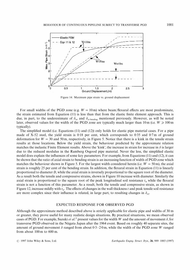
Figure 14. Maximum pipe strain vs. ground displacement
For small widths of the PGD zone (e.g. ¼"10m) where beam/flexural effects are most predominate,the strain estimated from Equation (11) is less than that from the elastic finite element approach. This isdue, in part, to the underestimate of d
#3and dcr-bending mentioned previously. However, as will be noted
later, observed values for the width of the PGD zone are typically much larger than 10m (i.e. ¼*100mtypically).
The simplified model (i.e. Equations (11) and (12)) only holds for elastic pipe material cases. For a pipemade of X-52 steel, the yield strain is 0·18 per cent, which corresponds to 0·35 and 0·7m of grounddeformation for ¼"30 and 50m, respectively, in Figure 5. Notice that there is a kink in the tensile strainresults at those locations. Below the yield strain, the behaviour predicted by the approximate relationmatches the inelastic Finite Element results. Above the ‘kink’, the increase in strain for increase in d is largerdue to the reduced modulus in the Ramberg Osgood pipe material. Never the less, the simplified elasticmodel does explain the influences of some key parameters. For example, from Equations (11) and (12), it canbe shown that the ratio of axial strain to bending strain is an increasing function of width of PGD zone whichmatches the behaviour shown in Figure 5. For the largest width considered herein (i.e. ¼"50 m), the axialstrain is roughly 25 per cent of the bending strain. In addition, the flexural strain in Equation (11) is linearlyproportional to diameter D, while the axial strain is inversely proportional to the square root of the diameter.As a result both the tensile and compressive strains, shown in Figure 10 increase with diameter. Similarly theaxial strain is proportional to the square root of the peak longitudinal soil resistance t
6while the flexural
strain is not a function of this parameter. As a result, both the tensile and compressive strain, as shown inFigure 12, increase mildly with t
6. The effects of changes in the wall thickness t and peak tensile soil resistance
are more complex since their influence is related, in large part, to resulting changes in d#3.
EXPECTED RESPONSE FOR OBSERVED PGD
Although the approximate method described above is strictly applicable for elastic pipe and widths of 30 mor greater, they prove useful for many realistic design situations. By practical situations, we mean observedcases of PGD. For example, Suzuki et al.2 present values for the width ¼ and the amount of movement d, fortransverse PGD observed in the Niigata Japan after the 1964 event. Based on roughly 40 separate sites, theamount of ground movement d ranged from about 0·3—2·0m, while the width of the PGD zone ¼ rangedfrom about 100m to 600 m.
BEHAVIOUR OF CONTINUOUS PIPELINE SUBJECT TO TRANSVERSE PGD 1001
( 1997 John Wiley & Sons, Ltd. Earthquake Engng. Struct. Dyn., 26, 989—1003 (1997)
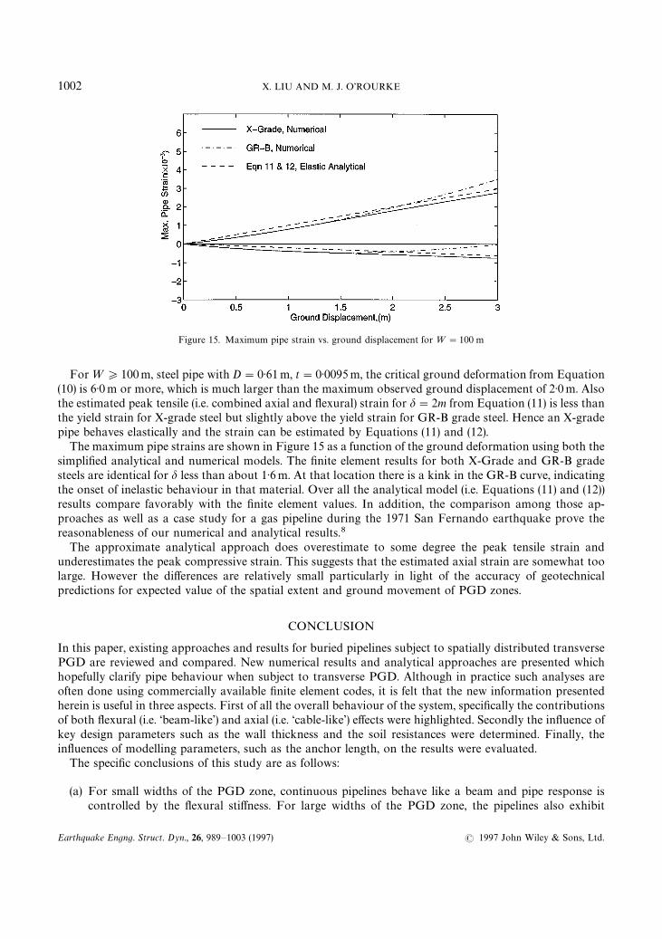
Figure 15. Maximum pipe strain vs. ground displacement for ¼"100 m
For ¼*100m, steel pipe with D"0·61m, t"0·0095m, the critical ground deformation from Equation(10) is 6·0m or more, which is much larger than the maximum observed ground displacement of 2·0m. Alsothe estimated peak tensile (i.e. combined axial and flexural) strain for d"2m from Equation (11) is less thanthe yield strain for X-grade steel but slightly above the yield strain for GR-B grade steel. Hence an X-gradepipe behaves elastically and the strain can be estimated by Equations (11) and (12).
The maximum pipe strains are shown in Figure 15 as a function of the ground deformation using both thesimplified analytical and numerical models. The finite element results for both X-Grade and GR-B gradesteels are identical for d less than about 1·6m. At that location there is a kink in the GR-B curve, indicatingthe onset of inelastic behaviour in that material. Over all the analytical model (i.e. Equations (11) and (12))results compare favorably with the finite element values. In addition, the comparison among those ap-proaches as well as a case study for a gas pipeline during the 1971 San Fernando earthquake prove thereasonableness of our numerical and analytical results.8
The approximate analytical approach does overestimate to some degree the peak tensile strain andunderestimates the peak compressive strain. This suggests that the estimated axial strain are somewhat toolarge. However the differences are relatively small particularly in light of the accuracy of geotechnicalpredictions for expected value of the spatial extent and ground movement of PGD zones.
CONCLUSION
In this paper, existing approaches and results for buried pipelines subject to spatially distributed transversePGD are reviewed and compared. New numerical results and analytical approaches are presented whichhopefully clarify pipe behaviour when subject to transverse PGD. Although in practice such analyses areoften done using commercially available finite element codes, it is felt that the new information presentedherein is useful in three aspects. First of all the overall behaviour of the system, specifically the contributionsof both flexural (i.e. ‘beam-like’) and axial (i.e. ‘cable-like’) effects were highlighted. Secondly the influence ofkey design parameters such as the wall thickness and the soil resistances were determined. Finally, theinfluences of modelling parameters, such as the anchor length, on the results were evaluated.
The specific conclusions of this study are as follows:
(a) For small widths of the PGD zone, continuous pipelines behave like a beam and pipe response iscontrolled by the flexural stiffness. For large widths of the PGD zone, the pipelines also exhibit
1002 X. LIU AND M. J. O’ROURKE
Earthquake Engng. Struct. Dyn., 26, 989—1003 (1997) ( 1997 John Wiley & Sons, Ltd.
‘cable-like’ behaviour and the pipe response is controlled, in part, by axial forces which are resisted byfriction at the pipe—soil interface outside of the PGD zone.
(b) For the pipe considered, flexural strains were larger than axial strain. In addition, peak tensile strain islarger than peak compressive strain.
(c) The assumed anchor length in FE models is an important parameter. Unrealistically, large pipe straincan be developed when the assumed anchor points are too close to the margins of the PGD zone.
(d) Using observed values for the amount and spatial extent of the PGD zone, it is shown that closed formanalytical relations developed herein can be used to estimate peak tension and compression strains.This simplified approach can be used for estimating pipe strain when the pipeline is surrounded bya variety of soil types. Specifically, the axial and lateral pipe-soil interaction forces are functions of thesoil properties.
ACKNOWLEDGEMENT
The work presented herein was sponsored by the National Center for Earthquake Engineering Research(NCEER). This support is gratefully acknowledged. However, all conclusions are the authors alone and donot necessarily reflect the views of NCEER.
REFERENCES
1. T. D. O’Rourke, ‘Critical aspects of soil—pipeline interaction for large ground deformation’, Proc. 1st Japan—º.S. ¼orkshop on¸iquefaction, ¸arge Ground Deformation and ¹heir Effects on ¸ifeline Facilities, November 1988, pp. 118—126.
2. N. Suzuki, T. Kobayashi, H. Nakane and M. Ishikawa, ‘Modelling of permanent ground deformation for buried pipelines’, Proc. 2ndº.S.—Japan ¼orkshop on ¸iquefaction, ¸arge Ground Deformation and ¹heir Effects on ¸ifelines, 1989, pp. 413—425.
3. M. J. O’Rourke, ‘Approximate analysis procedures for permanent ground deformation effects on buried pipelines’, Proc. 2ndº.S.—Japan ¼orkshop on ¸iquefaction, ¸arge Ground Deformation and ¹heir Effects on ¸ifelines, 1989, pp. 336—347.
4. M. J. O’Rourke, X. Liu, R. Flores-Berrones, ‘Steel pipe wrinkling due to longitudinal permanent ground deformation’, J ¹ransporta-tion Engng. 121, 443—451 (1995).
5. T. D. O’Rourke, M. J. O’Rourke, ‘Pipeline response to permanent ground deformation: a benchmark case’, Proc. 4th º.S. Conf. on¸ifeline Earthquake Engineering, TCLEE, ASCE, San Francisco, California, August 1995, pp. 288—295.
6. N. Suzuki, O. Arata and I. Suzuki, ‘Subject to liquefaction-induced permanent ground displacement’, Proc. 1st Japan—º.S. ¼orkshopon ¸iquefaction, ¸arge Ground Deformation and ¹heir Effects on ¸ifeline Facilities, November 1988, pp. 155—162.
7. ASCE, Guidelines for the Seismic Design of Oil and Gas Pipeline Systems, Committee on Gas and Liquid Fuel Lifeline, ASCE, 1984.8. X. Liu, Response of buried continuous pipelines subject to earthquake effects, Ph.D. Dissertation, Department of Civil Engineering,
Rensselear Polytechnic Institute, December, 1996, 143p.
.
BEHAVIOUR OF CONTINUOUS PIPELINE SUBJECT TO TRANSVERSE PGD 1003
( 1997 John Wiley & Sons, Ltd. Earthquake Engng. Struct. Dyn., 26, 989—1003 (1997)