Embed Size (px)
Citation preview
61:3 (2013) 79–85 | www.jurnalteknologi.utm.my | eISSN 2180–3722 | ISSN 0127–9696
Full paper Jurnal
Teknologi
Behavior of Eccentrically Loaded Plain and Steel Fiber Reinforced Concrete Filled Steel Box Columns Hanan Hussien Eltobgy
a*, Ibrahim Galal Shaaban
a, Salah Eldin Abdullah
a
aEngineering Department, Faculty of Engineering at Shoubra, Cairo, Postal Code 11241, Benha University, Egypt
*Corresponding author: [email protected]
Article history
Received :1 November 2012
Received in revised form :15 January
2013
Accepted :15 March 2013
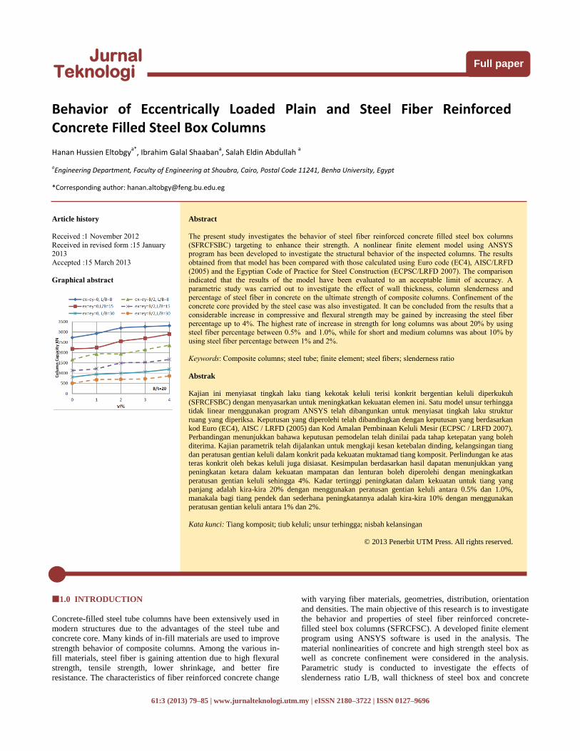
Graphical abstract
Abstract
The present study investigates the behavior of steel fiber reinforced concrete filled steel box columns
(SFRCFSBC) targeting to enhance their strength. A nonlinear finite element model using ANSYS
program has been developed to investigate the structural behavior of the inspected columns. The results
obtained from that model has been compared with those calculated using Euro code (EC4), AISC/LRFD
(2005) and the Egyptian Code of Practice for Steel Construction (ECPSC/LRFD 2007). The comparison indicated that the results of the model have been evaluated to an acceptable limit of accuracy. A
parametric study was carried out to investigate the effect of wall thickness, column slenderness and
percentage of steel fiber in concrete on the ultimate strength of composite columns. Confinement of the concrete core provided by the steel case was also investigated. It can be concluded from the results that a
considerable increase in compressive and flexural strength may be gained by increasing the steel fiber
percentage up to 4%. The highest rate of increase in strength for long columns was about 20% by using steel fiber percentage between 0.5% and 1.0%, while for short and medium columns was about 10% by
using steel fiber percentage between 1% and 2%.
Keywords: Composite columns; steel tube; finite element; steel fibers; slenderness ratio
Abstrak
Kajian ini menyiasat tingkah laku tiang kekotak keluli terisi konkrit bergentian keluli diperkukuh
(SFRCFSBC) dengan menyasarkan untuk meningkatkan kekuatan elemen ini. Satu model unsur terhingga tidak linear menggunakan program ANSYS telah dibangunkan untuk menyiasat tingkah laku struktur
ruang yang diperiksa. Keputusan yang diperolehi telah dibandingkan dengan keputusan yang berdasarkan
kod Euro (EC4), AISC / LRFD (2005) dan Kod Amalan Pembinaan Keluli Mesir (ECPSC / LRFD 2007). Perbandingan menunjukkan bahawa keputusan pemodelan telah dinilai pada tahap ketepatan yang boleh
diterima. Kajian parametrik telah dijalankan untuk mengkaji kesan ketebalan dinding, kelangsingan tiang
dan peratusan gentian keluli dalam konkrit pada kekuatan muktamad tiang komposit. Perlindungan ke atas teras konkrit oleh bekas keluli juga disiasat. Kesimpulan berdasarkan hasil dapatan menunjukkan yang
peningkatan ketara dalam kekuatan mampatan dan lenturan boleh diperolehi dengan meningkatkan
peratusan gentian keluli sehingga 4%. Kadar tertinggi peningkatan dalam kekuatan untuk tiang yang panjang adalah kira-kira 20% dengan menggunakan peratusan gentian keluli antara 0.5% dan 1.0%,
manakala bagi tiang pendek dan sederhana peningkatannya adalah kira-kira 10% dengan menggunakan
peratusan gentian keluli antara 1% dan 2%.
Kata kunci: Tiang komposit; tiub keluli; unsur terhingga; nisbah kelansingan
© 2013 Penerbit UTM Press. All rights reserved.
1.0 INTRODUCTION
Concrete-filled steel tube columns have been extensively used in
modern structures due to the advantages of the steel tube and
concrete core. Many kinds of in-fill materials are used to improve
strength behavior of composite columns. Among the various in-
fill materials, steel fiber is gaining attention due to high flexural
strength, tensile strength, lower shrinkage, and better fire
resistance. The characteristics of fiber reinforced concrete change
with varying fiber materials, geometries, distribution, orientation
and densities. The main objective of this research is to investigate
the behavior and properties of steel fiber reinforced concrete-
filled steel box columns (SFRCFSC). A developed finite element
program using ANSYS software is used in the analysis. The
material nonlinearities of concrete and high strength steel box as
well as concrete confinement were considered in the analysis.
Parametric study is conducted to investigate the effects of
slenderness ratio L/B, wall thickness of steel box and concrete
80 Hanan Hussien, Ibrahim Galal & Salah Eldin / Jurnal Teknologi (Sciences & Engineering) 61:3 (2013) 79–85
strength on the behavior and strength of the steel fiber reinforced
concrete filled steel box columns. The results obtained from the
finite element model has been compared with those obtained from
a recent experimental work made by Mursi, M. and Uy, B. (2003)
[1], Mursi, M. and Uy, B. (2004) [2], and Schneider (1998) [3],
as well as the results obtained using Euro-code (EC4)[4],
AISC/LRFD (2005) [5] and Egyptian code of practice for steel
construction ECPSC/LRFD (2007) [6].
2.0 FINITE ELEMENT MODEL
2.1 General
The physical behavior of steel fiber reinforced concrete-filled
steel box columns is simulated by modeling the components of
these columns. These components are; (a) the confined concrete
containing steel fibers, (b) the steel box, (c) the steel plates as a
loading jacks and (d) the interface between the concrete and the
steel box. In addition to these parameters, the choice of the
element type and mesh size that provide reliable results with
reasonable computational time is also important in simulating
structures with interface elements, Abdullah, S. (2012) [7].
2.2 Finite Element Type and Mesh
The concrete core of fiber reinforced concrete filled steel box
columns is modeled using 8-node brick elements, with three
translation degrees of freedom at each node (element; SOLID 65
in ANSYS12.0) [8]. Steel fibers is modeled in concrete using the
rebar option included in SOLID 65 real constant by defining the
steel fiber material properties, volumetric ratio and orientation
angle in x, y and z directions. The steel box is modeled using a 4-
node shell element, with six degrees of freedom at each node
(element; SHELL 63 in ANSYS12.0) [8]. Inelastic material and
geometric nonlinear behavior are used for this element. Von
Mises yield criteria is used to define the yield surface. No strain-
hardening is assumed for the steel box. Thus, if strain-hardening
characteristics are observed in concrete filled steel box column
behavior, it is primarily due to the interaction between the steel
and concrete components. A 50 mm thick steel plate, modeled
using (element; SOLID 45 in ANSYS12.0) [8], was added at the
support locations in order to avoid stress concentration problems
and to prevent localized crushing of concrete elements near the
supporting points and load application locations. The gap element
is used for the interface between the concrete and the steel
components. The gap element has two faces; when the faces are in
contact; compressive forces develop between the two materials
resulting in frictional forces. The friction coefficient used in the
analysis is 0.25. On the other hand, if the gap element is in
tension, the two faces become separated from each other, resulting
in no contact between the concrete and steel, and consequently no
bond is developed. TARGE170 is used to represent various 3-D
“target” surfaces for the associated contact elements
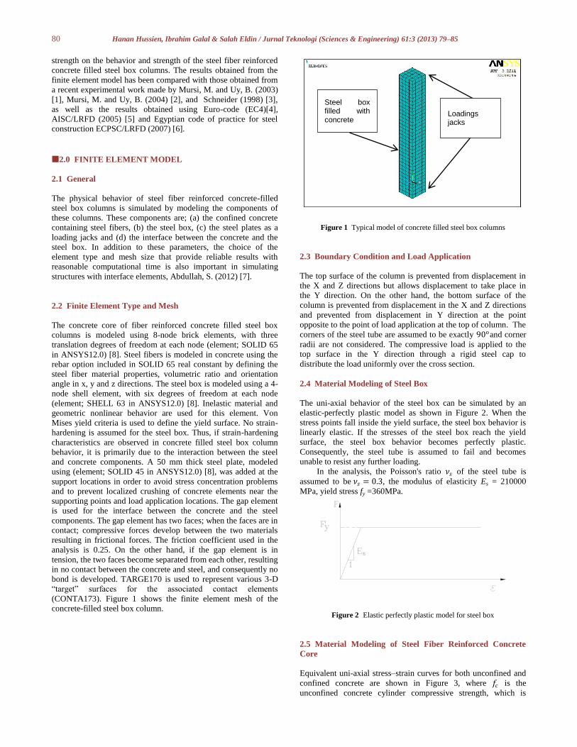
(CONTA173). Figure 1 shows the finite element mesh of the
concrete-filled steel box column.
Figure 1 Typical model of concrete filled steel box columns
2.3 Boundary Condition and Load Application
The top surface of the column is prevented from displacement in
the X and Z directions but allows displacement to take place in
the Y direction. On the other hand, the bottom surface of the
column is prevented from displacement in the X and Z directions
and prevented from displacement in Y direction at the point
opposite to the point of load application at the top of column. The
corners of the steel tube are assumed to be exactly 90oand corner
radii are not considered. The compressive load is applied to the
top surface in the Y direction through a rigid steel cap to
distribute the load uniformly over the cross section.
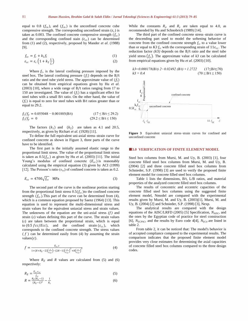
2.4 Material Modeling of Steel Box
The uni-axial behavior of the steel box can be simulated by an
elastic-perfectly plastic model as shown in Figure 2. When the
stress points fall inside the yield surface, the steel box behavior is
linearly elastic. If the stresses of the steel box reach the yield
surface, the steel box behavior becomes perfectly plastic.
Consequently, the steel tube is assumed to fail and becomes
unable to resist any further loading.
In the analysis, the Poisson's ratio 𝜈𝑠 of the steel tube is
assumed to be 𝜈𝑠 = 0.3, the modulus of elasticity Es = 210000
MPa, yield stress fy =360MPa.
Figure 2 Elastic perfectly plastic model for steel box
2.5 Material Modeling of Steel Fiber Reinforced Concrete
Core
Equivalent uni-axial stress–strain curves for both unconfined and
confined concrete are shown in Figure 3, where 𝑓𝑐 is the
unconfined concrete cylinder compressive strength, which is
Loadings jacks
Steel box filled with concrete
81 Hanan Hussien, Ibrahim Galal & Salah Eldin / Jurnal Teknologi (Sciences & Engineering) 61:3 (2013) 79–85
equal to 0.8 (𝑓𝑐𝑢 ), and (𝑓𝑐𝑢 ) is the unconfined concrete cube
compressive strength. The corresponding unconfined strain (𝜀𝑐) is
taken as 0.003. The confined concrete compressive strength (𝑓𝑐𝑐 )
and the corresponding confined stain (𝜀𝑐𝑐 ) can be determined
from (1) and (2), respectively, proposed by Mander et al. (1988)
[9].
𝑓𝑐𝑐 = 𝑓𝑐 + 𝑘1𝑓𝑙 (1)
𝜀𝑐𝑐 = 𝜀𝑐 1 + 𝑘2𝑓𝑙
𝑓𝑐 (2)
Where 𝑓𝑙 , is the lateral confining pressure imposed by the
steel box. The lateral confining pressure (𝑓𝑙) depends on the B/t ratio and the steel tube yield stress. The approximate value of (𝑓𝑙)
can be obtained from empirical equations given by Hu et al.
(2003) [10], where a wide range of B/t ratios ranging from 17 to
150 are investigated. The value of (𝑓𝑙) has a significant effect for
steel tubes with a small B/t ratio. On the other hand, the value of
(𝑓𝑙) is equal to zero for steel tubes with B/t ratios greater than or
equal to 29.2.
𝑓𝑙/𝑓𝑦 = 0.055048 − 0.001885(B/t) (17 ≤ B/t ≤ 29.2)
𝑓𝑙/𝑓𝑦 = 0 (29.2 ≤ B/t ≤ 150)
The factors (𝑘1) and (𝑘2) are taken as 4.1 and 20.5,
respectively, as given by Richart et al. (1928) [11].
To define the full equivalent uni-axial stress–strain curve for
confined concrete as shown in Figure 3, three parts of the curve
have to be identified.
The first part is the initially assumed elastic range to the
proportional limit stress. The value of the proportional limit stress
is taken as 0.5(𝑓𝑐𝑐 ) as given by Hu et al. (2003) [11]. The initial
Young‟s modulus of confined concrete (𝐸𝑐𝑐 ) is reasonably
calculated using the empirical equation (3) given by ACI (1999)
[12]. The Poisson‟s ratio (υcc) of confined concrete is taken as 0.2.
𝐸𝑐𝑐 = 4700 𝑓𝑐𝑐 MPa (3)
The second part of the curve is the nonlinear portion starting
from the proportional limit stress 0.5(𝑓𝑐𝑐 )to the confined concrete
strength (𝑓𝑐𝑐 ).This part of the curve can be determined from (4),
which is a common equation proposed by Saenz (1964) [13]. This
equation is used to represent the multi-dimensional stress and
strain values for the equivalent uniaxial stress and strain values.
The unknowns of the equation are the uni-axial stress (𝑓) and
strain (ε) values defining this part of the curve. The strain values
(ε) are taken between the proportional strain, which is equal
to (0.5 𝑓𝑐𝑐/𝐸𝑐𝑐), and the confined strain (𝜀𝑐𝑐), which
corresponds to the confined concrete strength. The stress values
( 𝑓 ) can be determined easily from (4) by assuming the strain
values(𝜀).
𝑓 =𝐸𝑐𝑐 𝜀
1+ 𝑅+𝑅𝐸−2 𝜀
𝜀𝑐𝑐 − 2𝑅−1
𝜀
𝜀𝑐𝑐
2+𝑅
𝜀
𝜀𝑐𝑐
3 (4)
Where 𝑅𝐸 and 𝑅 values are calculated from (5) and (6)
respectively:
𝑅𝐸 =𝐸𝑐𝑐 𝜀𝑐𝑐
𝑓𝑐𝑐 (5)
𝑅 =𝑅𝐸 𝑅𝜎−1
𝑅𝐸−1 2 −1
𝑅𝜀 (6)
While the constants 𝑅𝜎 and 𝑅𝜀 are taken equal to 4.0, as
recommended by Hu and Schnobrich (1989) [14].
The third part of the confined concrete stress–strain curve is
the descending part used to model the softening behavior of
concrete from the confined concrete strength fcc to a value lower
than or equal to K3 fcc with the corresponding strain of 11𝜀𝑐𝑐 . The
reduction factor (𝑘3) depends on the B/t ratio and the steel tube
yield stress 𝑓𝑦 . The approximate value of k3 can be calculated
from empirical equations given by Hu et al. (2003) [10].
k3=0.000178(B/t) 2−0.02492 (B/t) +1.2722 (17≤B/t≤70)
k3 = 0.4 (70 ≤ B/t ≤ 150)
f c
f
c cc cc11
f cc
c
f cck3
confined concrete
unconfined concrete
Pro
port
ional
Lim
it
0.5f cc
Figure 3 Equivalent uniaxial stress–strain curves for confined and
unconfined concrete
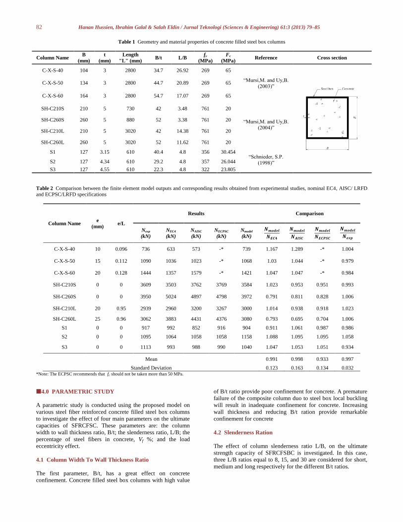
3.0 VERIFICATION OF FINITE ELEMENT MODEL
Steel box columns from Mursi, M. and Uy, B. (2003) [1], four
concrete filled steel box columns from Mursi, M. and Uy, B.
(2004) [2] and three concrete filled steel box columns from
Schnieder, S.P. (1998) [3] are used to verify the proposed finite
element model for concrete filled steel box columns.
Table 1 lists the dimensions, B/t, L/B ratios, and material
properties of the analyzed concrete filled steel box columns.
The results of concentric and eccentric capacities of the
concrete filled steel box columns using the suggested finite
element model, Nmodel are compared with the experimental
results given by Mursi, M. and Uy, B. (2003)[1], Mursi, M. and
Uy, B. (2004) [2] and Schnieder, S.P. (1998) [3], Nexp.
The analytical results are compared with the design
equations of the AISC/LRFD (2005) [5] Specification, NAISC, and
the ones by the Egyptian code of practice for steel construction
[6], NECPSC, and the results by Euro code 4[4], NEC4 are listed in
table 2.
From table 2, it can be noticed that: The model's behavior is
of accepted compliance compared to the experimental results. The
comparison indicates that the proposed finite element model
provides very close estimates for determining the axial capacities
of concrete filled steel box columns compared to the three design
codes.
82 Hanan Hussien, Ibrahim Galal & Salah Eldin / Jurnal Teknologi (Sciences & Engineering) 61:3 (2013) 79–85
Table 1 Geometry and material properties of concrete filled steel box columns
Column Name B
(mm)
t
(mm)
Length
"L" (mm) B/t L/B
fy
(MPa)
Fc
(MPa) Reference Cross section
C-X-S-40 104 3 2800 34.7 26.92 269 65
“Mursi,M. and Uy,B.
(2003)”
C-X-S-50 134 3 2800 44.7 20.89 269 65
C-X-S-60 164 3 2800 54.7 17.07 269 65
SH-C210S 210 5 730 42 3.48 761 20
“Mursi,M. and Uy,B. (2004)”
SH-C260S 260 5 880 52 3.38 761 20
SH-C210L 210 5 3020 42 14.38 761 20
SH-C260L 260 5 3020 52 11.62 761 20
S1 127 3.15 610 40.4 4.8 356 30.454 “Schnieder, S.P.
(1998)” S2 127 4.34 610 29.2 4.8 357 26.044
S3 127 4.55 610 22.3 4.8 322 23.805
Table 2 Comparison between the finite element model outputs and corresponding results obtained from experimental studies, nominal EC4, AISC/ LRFD
and ECPSC/LRFD specifications
Column Name e
(mm) e/L
Results Comparison
Nexp
(kN)
NEC4
(kN)
NAISC
(kN)
NECPSC
(kN)
Nmodel
(kN)
𝑵𝒎𝒐𝒅𝒆𝒍
𝑵𝑬𝑪𝟒
𝑵𝒎𝒐𝒅𝒆𝒍
𝑵𝑨𝑰𝑺𝑪
𝑵𝒎𝒐𝒅𝒆𝒍
𝑵𝑬𝑪𝑷𝑺𝑪
𝑵𝒎𝒐𝒅𝒆𝒍
𝑵𝒆𝒙𝒑
C-X-S-40 10 0.096 736 633 573 -* 739 1.167 1.289 -* 1.004
C-X-S-50 15 0.112 1090 1036 1023 -* 1068 1.03 1.044 -* 0.979
C-X-S-60 20 0.128 1444 1357 1579 -* 1421 1.047 1.047 -* 0.984
SH-C210S 0 0 3609 3503 3762 3769 3584 1.023 0.953 0.951 0.993
SH-C260S 0 0 3950 5024 4897 4798 3972 0.791 0.811 0.828 1.006
SH-C210L 20 0.95 2939 2960 3200 3267 3000 1.014 0.938 0.918 1.023
SH-C260L 25 0.96 3062 3883 4431 4376 3080 0.793 0.695 0.704 1.006
S1 0 0 917 992 852 916 904 0.911 1.061 0.987 0.986
S2 0 0 1095 1064 1058 1058 1158 1.088 1.095 1.095 1.058
S3 0 0 1113 993 988 990 1040 1.047 1.053 1.051 0.934
Mean 0.991 0.998 0.933 0.997
Standard Deviation 0.123 0.163 0.134 0.032 *Note: The ECPSC recommends that fc should not be taken more than 50 MPa.
4.0 PARAMETRIC STUDY
A parametric study is conducted using the proposed model on
various steel fiber reinforced concrete filled steel box columns
to investigate the effect of four main parameters on the ultimate
capacities of SFRCFSC. These parameters are: the column
width to wall thickness ratio, B/t; the slenderness ratio, L/B; the
percentage of steel fibers in concrete, Vf %; and the load
eccentricity effect.
4.1 Column Width To Wall Thickness Ratio
The first parameter, B/t, has a great effect on concrete
confinement. Concrete filled steel box columns with high value
of B/t ratio provide poor confinement for concrete. A premature
failure of the composite column duo to steel box local buckling
will result in inadequate confinement for concrete. Increasing
wall thickness and reducing B/t ration provide remarkable
confinement for concrete
4.2 Slenderness Ration
The effect of column slenderness ratio L/B, on the ultimate
strength capacity of SFRCFSBC is investigated. In this case,
three L/B ratios equal to 8, 15, and 30 are considered for short,
medium and long respectively for the different B/t ratios.

83 Hanan Hussien, Ibrahim Galal & Salah Eldin / Jurnal Teknologi (Sciences & Engineering) 61:3 (2013) 79–85
4.3 Percentage of Steel Fiber in Concrete Vf %
The third parameter concerns with the effect of steel fiber
percentage in concrete Vf %. The steel fiber percentage in
concrete is taken equal to 0% for plain concrete and up to 4%.
4.4 Effect of Load Application
The last parameter discusses the effect of loading application.
The compression loads are considered centric and eccentric. The
eccentricity effect (ex B and ey B ) is considered to be equal to
0.5.
The geometry and material properties of the analyzed steel
fiber reinforced concrete filled steel box columns are illustrated
in Table 3.
Table 3 Geometry and material properties of concrete filled steel box
columns
Co
lum
ns
Dimensions
(mm)
L/B
ra
tio
B/t
ra
tio
Concrete
Strength S
teel
yie
ld s
tren
gth
Un
co
nfi
ned
Co
nfi
ned
B t L
fc fcc fy
(MPa)
C01
200 10
1600 8
20 30 55.6 360 C02 3000 15 C03 6000 30
C04
200 8
1600 8
25 30 41.7 360 C05 3000 15 C06 6000 30
C07
200 5
1600 8
40 30 30 360 C08 3000 15 C09 6000 30
5.0 DISCUSSION OF THE RESULTS
5.1 Effect of Steel Plate Wall Thickness
Wall thickness of steel box has a great effect on short to
medium height columns. Compact steel plate for column wall
thickness provides more confinement to the concrete core that
contributes to an increase in the overall column capacity. Non-
compact steel plate for wall column thickness provides less
confinement that will result in substantial decrease in the
column's capacity. The effect of column wall thickness on long
columns has a less effect on the column behavior due to the
overall column buckling. Figure 4 indicates the axial and
eccentric capacity versus B/t ratio for different L/B ratios.
5.2 Effect of Column Slenderness Ratio
The increase in column's height has a minor effect on short and
medium columns, the fail is attributed to the inelastic bucking,
meaning that, the column fails by the crushing of concrete
and/or yielding of the steel plates then the column capacity
decreases in percentage ranges from 3 % to 30 %, while for long
columns, the column's height has a great influence on the
column's capacity that fails due to overall buckling before the
crushing of concrete and/or yielding of the column steel plates.
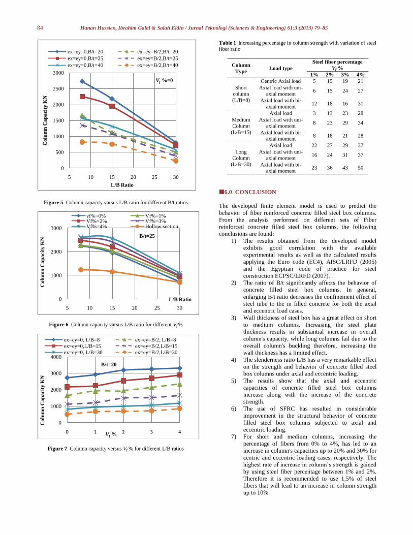
Figure 5 shows the axial and eccentric column's capacity versus
L/B ratio for different B/t ratios, and Figure 6 shows axial
column capacity versus L/B ratio for different value of Vf %.
5.3 Effect of Percentage of Steel Fiber
Figure 7 plots the axial and eccentric column capacity versus
steel fiber percentage in the in-filed concrete, Vf % for different
B/t and L/B ratios. Table 4 presents the percentage of increase
in column capacities with the increase in Vf % for the different
columns‟ aspect ratios, under the different axial centric and
eccentric load cases.
For short and medium columns, increasing the percentage
of fibers from 0% to 4%, will lead to an increase in column's
capacity in percentage varies from 3% to 28% for axial load and
from 6% to 30% for eccentric load. The highest rate of increase
lies within a percentage of fibers between 1% and 2%.
Therefore it is recommended to use 1.5% of steel fibers in case
of short and medium columns.
For long columns, increasing the percentage of fibers from
0% to 4%, will lead to an increase in column's capacity by
percentage varies from 22% to 37% for axial load, and from
16% to 50% for eccentric load. The highest rate of increase lies
between 0% and 1%. Therefore it is recommended to use 0.5%
of steel fibers in case of long column.
Figure 4 Column capacities versus B/t ratio for different L/B ratios
0
500
1000
1500
2000
2500
3000
20 25 30 35 40
Co
lum
n C
ap
acit
y K
N
B/t Ratio
Vf %=0
ex=ey=0,L/B=8 ex=ey=B/2,L/B=8
ex=ey=0,L/B=15 ex=ey=B/2,L/B=15
ex=ey=0,L/B=30 ex=ey=B/2,L/B=30
84 Hanan Hussien, Ibrahim Galal & Salah Eldin / Jurnal Teknologi (Sciences & Engineering) 61:3 (2013) 79–85
Figure 5 Column capacity varsus L/B ratio for different B/t ratios
Figure 6 Column capacity varsus L/B ratio for different Vf %
Figure 7 Column capacity versus Vf % for different L/B ratios
Table 1 Increasing percentage in column strength with variation of steel fiber ratio
Column
Type Load type
Steel fiber percentage
Vf %
1% 2% 3% 4%
Short
column (L/B=8)
Centric Axial load 5 15 19 21
Axial load with uni-
axial moment 6 15 24 27
Axial load with bi-
axial moment 12 18 16 31
Medium Column
(L/B=15)
Axial load 3 13 23 28
Axial load with uni-axial moment
8 23 29 34
Axial load with bi-
axial moment 8 18 21 28
Long Column
(L/B=30)
Axial load 22 27 29 37
Axial load with uni-axial moment
16 24 31 37
Axial load with bi-
axial moment 23 36 43 50
6.0 CONCLUSION
The developed finite element model is used to predict the
behavior of fiber reinforced concrete filled steel box columns.
From the analysis performed on different sets of Fiber
reinforced concrete filled steel box columns, the following
conclusions are found:
1) The results obtained from the developed model
exhibits good correlation with the available
experimental results as well as the calculated results
applying the Euro code (EC4), AISC/LRFD (2005)
and the Egyptian code of practice for steel
construction ECPSC/LRFD (2007).
2) The ratio of B/t significantly affects the behavior of
concrete filled steel box columns. In general,
enlarging B/t ratio decreases the confinement effect of
steel tube to the in filled concrete for both the axial
and eccentric load cases.
3) Wall thickness of steel box has a great effect on short
to medium columns. Increasing the steel plate
thickness results in substantial increase in overall
column's capacity, while long columns fail due to the
overall column's buckling therefore, increasing the
wall thickness has a limited effect.
4) The slenderness ratio L/B has a very remarkable effect
on the strength and behavior of concrete filled steel
box columns under axial and eccentric loading.
5) The results show that the axial and eccentric
capacities of concrete filled steel box columns
increase along with the increase of the concrete
strength.
6) The use of SFRC has resulted in considerable
improvement in the structural behavior of concrete
filled steel box columns subjected to axial and
eccentric loading.
7) For short and medium columns, increasing the
percentage of fibers from 0% to 4%, has led to an
increase in column's capacities up to 20% and 30% for
centric and eccentric loading cases, respectively. The
highest rate of increase in column‟s strength is gained
by using steel fiber percentage between 1% and 2%.
Therefore it is recommended to use 1.5% of steel
fibers that will lead to an increase in column strength
up to 10%.
0
500
1000
1500
2000
2500
3000
5 10 15 20 25 30
Co
lum
n C
ap
acit
y K
N
L/B Ratio
Vf %=0
ex=ey=0,B/t=20 ex=ey=B/2,B/t=20
ex=ey=0,B/t=25 ex=ey=B/2,B/t=25
ex=ey=0,B/t=40 ex=ey=B/2,B/t=40
0
1000
2000
3000
5 10 15 20 25 30
Co
lum
n C
ap
acit
y K
N
L/B Ratio
B/t=25
vf%=0% Vf%=1%Vf%=2% Vf%=3%Vf%=4% Hollow section
0
1000
2000
3000
4000
0 1 2 3 4
Co
lum
n C
ap
acit
y K
N
Vf %
B/t=20
ex=ey=0, L/B=8 ex=ey=B/2, L/B=8
ex=ey=0,L/B=15 ex=ey=B/2,L/B=15
ex=ey=0, L/B=30 ex=ey=B/2,L/B=30
85 Hanan Hussien, Ibrahim Galal & Salah Eldin / Jurnal Teknologi (Sciences & Engineering) 61:3 (2013) 79–85
For long columns, increasing the percentage of fibers from 0%
to 4% has led to an increase in column's capacity up to 50%.
The biggest rate of increase in column strength is gained by
using steel fiber percentage between 0% and 1%. Therefore it is
recommended to use 0.5% of steel fibers that will lead to an
increase in column strength up to 20%.
References
[1] Mursi, M. and Uy, B. 2003. Strength of Concrete Filled Steel Box
Columns Incorporating Interaction Buckling. Journal of Structural Engineering, ASCE. 129(5): 626–639.
[2] Mursi, M. and Uy, B. 2004. Strength of Slender Concrete Filled High Strength Steel Box Columns. Journal of Constructional Steel Research. 60: 1825–1848.
[3] Schneider, S. P. 1998. Axially Loaded Concrete-Filled Steel Tubes. Journal of Structural Engineering, ASCE. 124(10): 1125–1138.
[4] Euro code 4. 2004 Design of Composite Steel and Concrete Structures. Part 1.1, General Rules and Rules for Buildings (with UK national application document), DD ENV 1994-1-1. London (UK): British Standards Institution.
[5] ANSI/AISC, 360-05. 2005 Specifications for Structural Steel Buildings (ASD/LRFD). Chicago, Illinois.
[6] Egyptian Code of Practice for Steel Construction. 2007. LRFD, (Load and Resistance Factor Design).
[7] Abdullah, S. 2012. Structural Behavior of Fiber Reinforced Concrete Filled Steel Box Columns. M.Sc. Thesis, Faculty of Engineering at Shoubra, Benha University, Egypt. 120.
[8] ANSYS Verification Manual, Release 12.0. ANSYS, Inc. 2009. United States.
[9] Mander, J. B., Priestley, M. J. N., and Park, R. 1988. Theoretical stress–Strain Model for Confined Concrete. Journal of Structural Engineering, ASCE. 114(8): 1804–1826.
[10] Hu, H. T., Huang, C. S., Wu, M. H., and Wu, Y. M. 2003. Nonlinear Analysis of Axially Loaded Concrete-filled Tube Columns with Confinement Effect. Journal of Structural Engineering, ASCE. 129(10): 1322–1329.
[11] Richart, F. E., Brandzaeg, A., and Brown, R. L. 1928. A Study Of The Failure of Concrete Under Combined Compressive Stresses. Bull. 185. Champaign (IL, USA): University of Illinois Engineering Experimental Station.
[12] ACI. 1999. Building Code Requirements For Structural Concrete and Commentary. ACI 318-99. Detroit (USA): American Concrete Institute.
[13] Saenz, L. P. 1964. Discussion of „Equation for the Stress–strain Curve of Concrete by P. Desayi, and S. Krishnan. Journal of the American Concrete Institute. 61: 1229–1235.
[14] Hu, H. T., and Schnobrich, W. C. 1989. Constitutive Modeling of Concrete by Using Non-Associated Plasticity. Journal of Materials in Civil Engineering. 1(4):199–216.