Embed Size (px)
Citation preview
International Journal of Scientific and Research Publications, Volume 2, Issue 6, June 2012 1 ISSN 2250-3153
www.ijsrp.org
Effect of in-plane forces on frequency parameters
A.K.L. Srivastava, S.R.Pandey
* Department of Civil Engineering, N. I. T. Jamshedpur- 831014, India
Abstract- Vibration and buckling characteristics of stiffened
plates subjected to in-plane uniform and non-uniform edge
loading at the plate boundaries are investigated using the finite
element method. Rectangular stiffened plates possessing
different boundary conditions, aspect ratios, varying mass and
stiffness properties and varying number of stiffeners have been
analyzed for buckling and vibration studies. The characteristic
equations for the natural frequencies, buckling loads and their
corresponding mode shapes are obtained from the equation of
motion. The effects of the position of stiffeners and number of
stiffeners, aspect ratios, boundary conditions, stiffeners
parameters upon the buckling load parameter and fundamental
frequency of the stiffened plates are investigated. The results are
obtained considering the bending displacements of the plate and
the stiffener. Eccentricity of the stiffeners gives rise to axial and
bending displacement in the middle plane of the plate.
Comparison with published results indicates good agreement. In
the structure modelling, the plate and the stiffeners are treated as
separate elements where the compatibility between these two
types of elements is maintained.
Index Terms- Finite element method, Stiffened plate,
Buckling and frequency parameter, Stiffeners parameters
Notations
a - Plate dimension in longitudinal direction
b - Plate dimension in the transverse direction
t - Plate thickness
E, G - Young’s and shear moduli for the plate material
b s , d s - web thickness and depth of a x-stiffener
,
- Non –dimensional element coordinate
A S - Cross sectional area of the stiffener
SI - Moment of inertia of the stiffener cross-section about
reference axis
{q} r - Vector of nodal displacement a rth
node
[D P ] - Rigidity matrix of plate
[D S ] - Rigidity matrix of stiffener
[K e ] - Elastic stiffness matrix of plate
[K S ] - Elastic stiffness matrix of stiffener
Sp MM , - Consistent mass matrix of plate, stiffener
[K G ] - Geometric stiffness matrix
[N] r - Matrix of a shape function of a node r
P cr - Critical buckling load
P (t) - In plane load
ST - Torsional constant
SP - Polar moment of inertia of the stiffener element
I. INTRODUCTION
he dynamic behaviour of stiffened plates has been the
subject of intensive study for many years. For aerodynamic
considerations, stiffener will be provided inside the hull of
aircraft and for space structures the stringer can be provided
outside if that is more structurally efficient. Stiffened plates are
structural components consisting of plates reinforced by a system
of ribs to enhance their load carrying capacities. These structures
are widely used in aircraft, ship, bridge, building, and some other
engineering activities. In many circumstances these structures are
found to be exposed to in-plane loading.
The buckling and vibration characteristics of stiffened plates
subjected to uniform and non-uniform in-plane edge loading are
of considerable importance to aerospace, naval, mechanical and
structural engineers. Aircraft wing skin panels, which are made
of thin sheets are usually subjected to non-uniform in-plane
stresses caused by concentrated or partial edge loading at the
edges, and due to panel stiffener support conditions
Diez et al. [1] studied the effect of combined normal and
shear in-plane loads by the Galerkin method. Transverse
vibration of rectangular plates subjected to in-plane forces under
various combinations has been studied by Singh and Dey [2] by a
difference based variational approach.
The vibration and buckling of partially loaded simply
supported plates were studied by Deolasi et al. [3]. Recently
Sundersan et al. [4] have studied the influence of partial edge
compression on buckling behaviour of angle ply plates for a few
orientations.
A brief literature survey reveals that a variety of methods
have been proposed to study the vibration of stiffened plates. The
most common method used in early literature was to approximate
the stiffened plate as equivalent orthotropic plates, using the
smeared stiffener approach. In more recent literature, with the
help of high-speed computers, the plate and stiffeners were
treated separately. Such numerical methods as the finite element
method and finite difference method are widely used.
Aksu [5] has presented a variational principle in conjunction
with the finite difference method for analysis of free vibration of
uni-directionally and cross-stiffened plates considering in-plane
inertia and in plane displacements in both directions.
T
International Journal of Scientific and Research Publications, Volume 2, Issue 6, June 2012 2
ISSN 2250-3153
www.ijsrp.org
Shastry and Rao [6] have used the 3 noded conforming
element and refined beam-bending element for arbitrary oriented
stiffeners.
Olson and Hazell [7] have presented a critical study on
clamped integrally stiffened plate by the finite element method.
The mode shapes and frequencies have been determined
experimentally using the real time holographic technique. The
effect of change in rib stiffness on various modes has been
studied.
Bapu Rao et al. [8] have also reported their work on
experimental determination of frequencies with real time
holographic technique for skew stiffened cantilever plates.
Mukhopadhyay [9] has applied the semi-analytic finite difference
method to the stability analysis of rectangular stiffened plates
based on the plate beam idealization.
Sheikh and Mukhopadhyay [10] applied the spline finite strip
method to the free vibration analysis of stiffened plates of
arbitrary shapes. They analyzed the plate of rectangular, skew
and annular shapes with concentric as well as eccentric stiffeners.
Large amplitude, free flexural vibration of stiffened plates has
been investigated by the spline finite strip method by Sheikh and
Mukhopadhyay [11]. The stiffener has been elegantly modelled
so that it can be placed anywhere within the plate strip.
Harik and Guo [12] have developed a compound finite
element model to investigate the stiffened plates in free vibration
where they have treated the beam and plate element as the
integral part of a compound section, and not as independent
bending components.
Bedair [13] has studied the free vibration characteristics of
stiffened plates due to plate/stiffener proportions. He has
considered the plate and the stiffener as the discrete elements
rigidly connected at their junctions and the nonlinear strain
energy function of the assembled structure has been transformed
into an unconstrained optimization problem to which Sequential
quadratic programming has been applied to determine the
magnitudes of the lowest natural frequency and the associated
mode shape
Allman [14] has carried out the analysis of buckling loads of
square and rectangular stiffened plates using triangular element.
He has presented the results both by including and neglecting the
torsional stiffness of the stiffeners. Vibration of stiffened plates
with elastically restrained edges has been analyzed by Wu and
Liu [15] using Rayleigh-Ritz method. The first four lower
frequencies for restrained plates up to six intermediate stiffeners
are calculated.
Mukhopadhyay [16] has extended the static and vibration
analysis of plates to analyse the stability of ship plating and
allied plated structures using the semi-analytic method.
An isoparametric stiffened plate bending element for the
buckling analysis of stiffened plate has been presented by
Mukherjee and Mukhopadhyay [17]. Here the stiffener can be
positioned anywhere within the plate element and need not
necessarily be placed on the nodal lines.The general spline finite
strip method has been extended by Sheikh and Mukhopadhyay
[18] to analyse stiffened plate of arbitrary shape. Stiffened plates
having various shapes, boundary conditions and also possessing
various dispositions of stiffeners have been analyzed by the
proposed method. The stability of partially stiffened, simply
supported and clamped square plates is studied by Roy et al.
[19]. A high precision triangular finite element and a compatible
stiffener element are used in the finite element analysis. Buckling
of stiffened plates has been studied by Bedair [20]. An
investigation on stiffened plates has been conducted to determine
the elastic parameters as well as the cross-sectional dimensions
of rectangular stiffeners from experimental modal data and finite
element prediction, using model-updating technique by
Chakraborty and Mukhopadhyay [21].
A differential quadrature analysis for the free vibration of
eccentrically stiffened plates is studied by Zeng and Bert [22].
The plate and the stiffeners are separated at the interface with
equilibrium and continuity condition satisfied. Vibration and
dynamic stability of stiffened plates subjected to in-plane
uniform harmonic edge loading is studied using finite element
analysis by Srivastava et al. [23] considering and neglecting in-
plane displacements. Further Srivastava et al [24] extended their
work to study the principal dynamic instability behaviour of
stiffened plates subjected to non-uniform harmonic in-plane edge
loading. Various methods used for vibration analysis such as Ritz
technique, Levy’s solution, finite difference method, finite
element method, Galerkin method, differential quadrature
method and method using boundary characteristics orthogonal
polynomials (BCOP) have been reviewed extensively by Leissa
[25]. The effect of the gap between the stiffener tip and the
supporting edge on the natural frequencies has been investigated
by Nair and Rao [26]. The panel is represented by triangular
plate bending elements and the stiffener by beam elements.
The applied load is seldom uniform and the boundary
conditions may be completely arbitrary in practice. The problem
becomes complicated when the numbers of stiffeners are
increasing regardless of the position of stiffeners not necessary
along the nodal lines. Loading is non-uniformly distributed over
the edges and along the stiffeners thus affecting the boundary
conditions. Analysis of stiffened plate is carried out normally by
energy method by adding energies due to plate and stiffener. The
energy stored in the stiffener will depend on its cross section and
if a thin walled open section, the effect of twisting as well as
warping have to be included. These studies for most part being
concerned with the numerical analysis of the theoretical buckling
load and also mostly related to unstiffened plates.
The present paper deals with the problem of vibration and
buckling of rectangular stiffened plates subjected to in-plane
uniform and non-uniform edge loading. Finite element
formulation is applied for obtaining the non-uniform stress
distribution in the plate and also to solve the buckling load and
frequency parameters in various modes with different boundary
conditions, aspect ratios and various parameters of stiffened
plates. The analysis presented determines the stresses all over the
region. In the present analysis, the plate is modeled with the nine
nodded isoperimetric quadratic element where the contributions
of bending and membrane actions are taken into account. Thus
the analysis can be carried out for both thin and thick plates.
Moreover it can be applied to a structure having irregular
boundaries. The formulation of the stiffener is done in such a
manner so that it may lie anywhere within a plate element. In
order to maintain compatibility between plate and stiffener, the
interpolation functions used for the plate are used for the
stiffeners also.
International Journal of Scientific and Research Publications, Volume 2, Issue 6, June 2012 3
ISSN 2250-3153
www.ijsrp.org
II. MATHEMATICAL FORMULATION
The governing equations for the buckling and vibration of
stiffened plates subjected to in-plane harmonic edge loading are
developed. The presence of uniform and non-uniform external
in-plane loads, boundary conditions, stiffeners locations and
cutouts if any in the plate induce a non-uniform stress field in the
structures. This necessitates the determination of the stress field
as a prerequisite to the solution of the problems like vibration,
buckling and vibration behaviour of stiffened plates. As the
thickness of the structure is relatively smaller, the determination
of stress field reduces to the solution of a plane stress problem in
the plate skin and stiffeners (where the thickness and breath are
small compared to length). The stiffened plates are modeled and
the governing equations are solved by finite element method. In
the present analysis, the plate is modelled with nine noded
isoparametric quadratic elements where the contributions of
bending and membrane actions are taken into account. One of the
advantages of the element is that it includes the effect of shear
deformation and rotary inertia in its formulation. Thus the
analysis can be carried out for both thin and thick plates.
Moreover it can be applied to a structure having irregular
boundaries. Also it can handle any position of cutout, different
boundary and position of in-plane concentrated loads or loading
conditions. In order to maintain compatibility between plate and
stiffener, the interrelation functions used for the plate are used
for the stiffeners also. Numerical methods like finite element
method (FEM) are preferred for problems involving complex in
plane loading and boundary conditions as analytical methods are
not easily adaptable. The formulation is based on Mindlin's plate
theory, which will allow for the incorporation of shear
deformation. The plate skin and the stiffeners/composite are
modelled as separate elements but the compatibility between
them is maintained. The nine noded isoparametric quadratic
elements with five degrees of freedom (u, v, w, X and y ) per
node have been employed in the present analysis.
The in-plane displacements u and v need to be considered
only when the stiffeners are connected eccentrically to the plate.
If the plate and stiffeners are connected concentrically, no in
plane stresses develop The effect of in-plane deformations is
taken into account in addition to the deformations due to
bending, which will help to model the stiffener eccentricity
conveniently. The element matrices of the stiffened plate element
consist of the contribution of the plate and that of the stiffener.
in the power of the thickness co-ordinate as:
The explicit evaluation of integrals involved in the evaluation
of element stiffness and mass matrices of the plate is tedious and
as such is not attempted. A Gaussian integration technique has
been adopted for this purpose for its high accuracy and also it can
be implemented easily. A exact integration needs an order of 3 x
3. However, a reduced integration proves to be more effective
and cheaper. To integrate the element matrices a 2 x 2 Gaussian
integration has been adopted, however, the order of integration
has been mentioned.
To integrate the element matrices a 2 x 2 Gaussian integration has been adopted, however, the order of integration has been
mentioned.
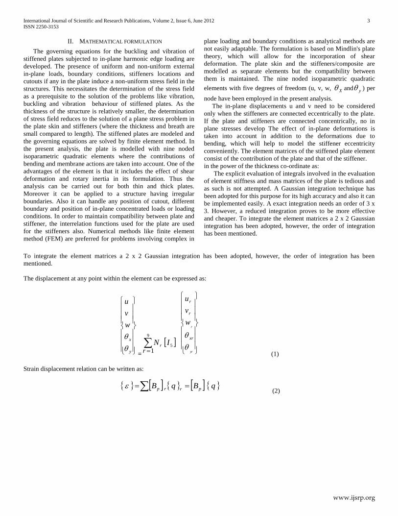
The displacement at any point within the element can be expressed as:
y
x
w
v
u
=
9
5
1r
IN r
yr
r
xr
r
r
w
v
u
(1)
Strain displacement relation can be written as:
qBqB prrp (2)
International Journal of Scientific and Research Publications, Volume 2, Issue 6, June 2012 4
ISSN 2250-3153
www.ijsrp.org
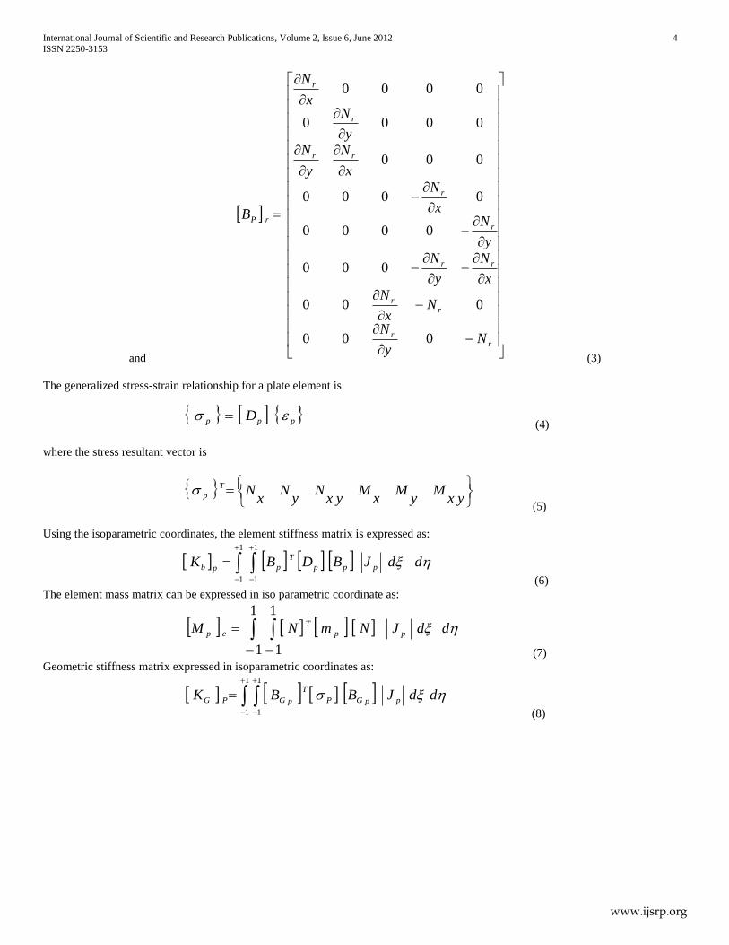
and
rr
rr
rr
r
r
rr
r
r
rP
Ny
N
Nx
N
x
N
y
N
y
Nx
N
x
N
y
N
y
Nx
N
B
000
000
000
0000
0000
000
0000
0000
(3)
The generalized stress-strain relationship for a plate element is
ppp D
(4)
where the stress resultant vector is
yx
My
Mx
Myx
Ny
Nx
NT
p (5)
Using the isoparametric coordinates, the element stiffness matrix is expressed as:
1
1
1
1
ddJBDBK ppp
T
ppb
(6)
The element mass matrix can be expressed in iso parametric coordinate as:
1
1
1
1
ddJNmNM pp
T
ep
(7)
Geometric stiffness matrix expressed in isoparametric coordinates as:
1
1
1
1
ddJBBK ppGP
T
pGPG
(8)
International Journal of Scientific and Research Publications, Volume 2, Issue 6, June 2012 5
ISSN 2250-3153
www.ijsrp.org
120
12000
012
012
00
120
12000
012
012
00
0000
0000
33
33
33
33
tt
tt
tt
tt
tt
tt
yxy
xxy
xyy
xyx
yxy
xyx
P
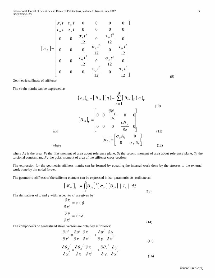
(9)
Geometric stiffness of stiffener
The strain matrix can be expressed as
9
1rrqrBqB GSGSGS
(10)
and
0000
0000
x
rN
x
rN
rBGS
(11)
where
SX
Sx
S S
A
0
0
(12)
where AS is the area, FS the first moment of area about reference plane, SS the second moment of area about reference plane, TS the
torsional constant and PS the polar moment of area of the stiffener cross-section.
The expression for the geometric stiffness matrix can be formed by equating the internal work done by the stresses to the external
work done by the nodal forces.
The geometric stiffness of the stiffener element can be expressed in iso-parametric co- ordinate as:
dJBBK SGSS
T
SGSG
1
1 (13)
The derivatives of x and y with respect to x / are given by
sin
cos
/
/
x
y
x
x
(14)
The components of generalized strain vectors are obtained as follows:
/
/
/
/
/
/
x
y
y
u
x
x
x
u
x
u
(15)
/
/
/
/
/
/
x
y
yx
x
xx
xxx
(16)
International Journal of Scientific and Research Publications, Volume 2, Issue 6, June 2012 6
ISSN 2250-3153
www.ijsrp.org
/
/
/
/
/
/
x
y
yx
x
xx
y yy
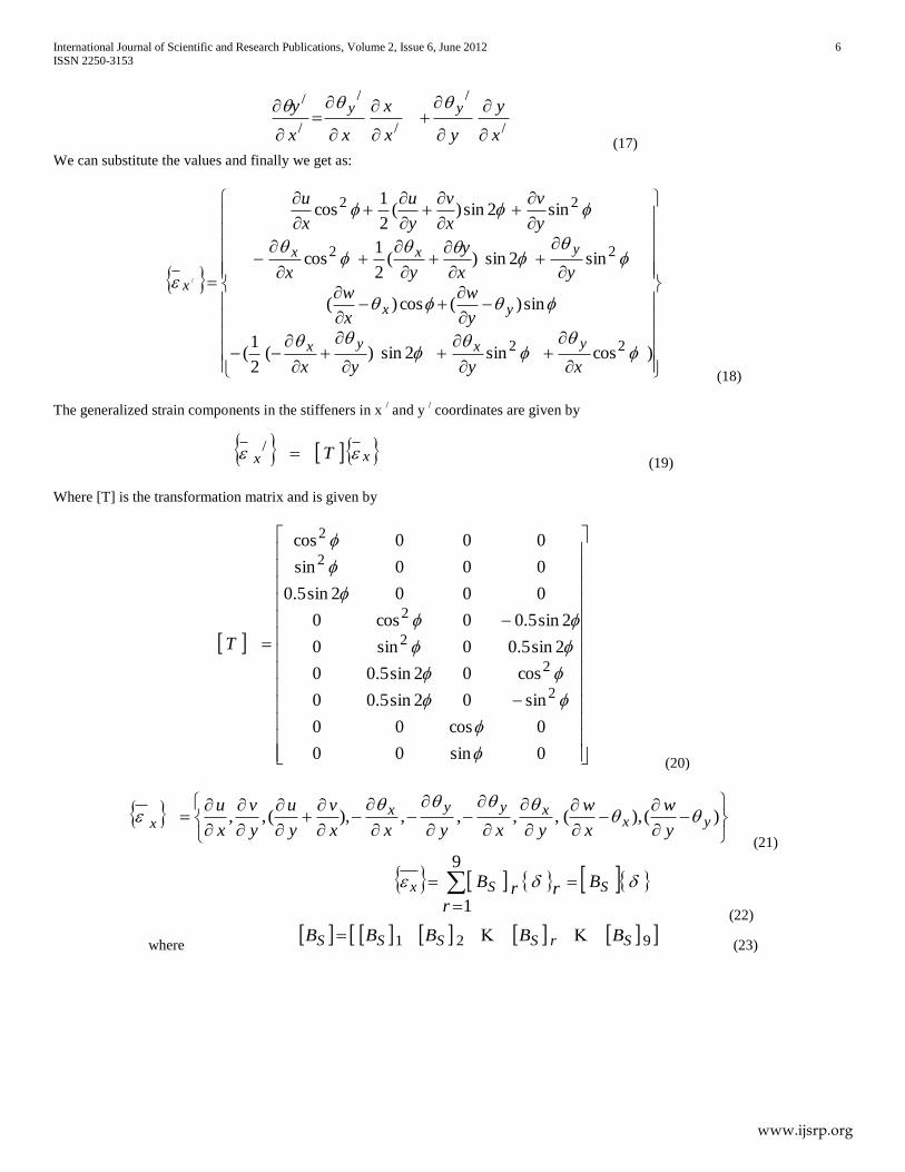
(17)
We can substitute the values and finally we get as:
)cossin2sin)(2
1(
sin)(cos)(
sin2sin)(2
1cos
sin2sin)(2
1cos
22
22
22
/
xyyx
y
w
x
w
yx
y
yx
y
v
x
v
y
u
x
u
yxyx
yx
yxx
x
(18)
The generalized strain components in the stiffeners in x / and y
/ coordinates are given by
xx T /
(19)
Where [T] is the transformation matrix and is given by
0sin00
0cos00
sin02sin5.00
cos02sin5.00
2sin5.00sin0
2sin5.00cos0
0002sin5.0
000sin
000cos
2
2
2
2
2
2
T
(20)
)(),(,,,,),(,, yx
xyyxx y
w
x
w
yxyxx
v
y
u
y
v
x
u
(21)
9
1r
BrrB SSx
(22)
where 921 SrSSSS BBBBB
(23)
International Journal of Scientific and Research Publications, Volume 2, Issue 6, June 2012 7
ISSN 2250-3153
www.ijsrp.org
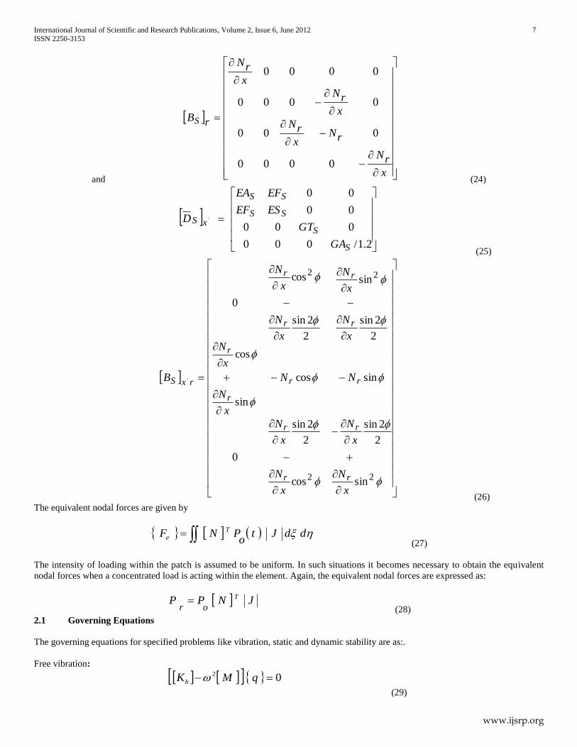
and
x
rN
rNx
rN
x
rN
x
rN
rBS
0000
000
0000
0000
(24)
2.1/000
000
00
00
'
S
S
SS
SS
xS
GA
GT
ESEF
EFEA
D
(25)
22
22
sin
2
2sin
cos
2
2sin
0
sincos
sin
cos
2
2sin
sin
2
2sin
cos
0
/
x
N
x
N
x
N
x
N
NN
x
N
x
Nx
N
x
N
x
N
x
N
B
r
r
r
r
rr
r
r
r
r
r
r
rxS
(26)
The equivalent nodal forces are given by
ddJto
PNF T
e (27)
The intensity of loading within the patch is assumed to be uniform. In such situations it becomes necessary to obtain the equivalent
nodal forces when a concentrated load is acting within the element. Again, the equivalent nodal forces are expressed as:
JNPP T
or
(28)
2.1 Governing Equations
The governing equations for specified problems like vibration, static and dynamic stability are as:.
Free vibration:
02 qMKb
(29)
International Journal of Scientific and Research Publications, Volume 2, Issue 6, June 2012 8
ISSN 2250-3153
www.ijsrp.org
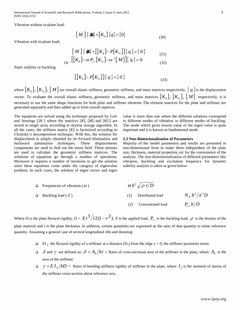
Vibration without in-plane load:
0 qKqM b
(30)
Vibration with in-plane load:
0 qKPKqM Gb
(31)
Or 02 qMKPK Grcb
(32)
Static stability or buckling
0 qKPK Gb (33)
where bK , GK , M are overall elastic stiffness, geometric stiffness, and mass matrices respectively, q is the displacement
vector. To evaluate the overall elastic stiffness, geometric stiffness, and mass matrices bK , GK , M respectively, it is
necessary to use the same shape functions for both plate and stiffener elements The element matrices for the plate and stiffener are
generated separately and then added up to form overall matrices.
The equations are solved using the technique proposed by Corr
and Jennings [28 ] where the matrices [K], [M] and [KG] are
stored in single array according to skyline storage algorithm. In
all the cases, the stiffness matrix [K] is factorized according to
Cholesky’s decomposition technique. With this, the solution for
displacement is simply obtained by its forward elimination and
backward substitution techniques. These displacements
components are used to find out the stress field. These stresses
are used to calculate the geometric stiffness matrices. The
solutions of equations go through a number of operations.
Moreover it requires a number of iterations to get the solution
since these equations come under the category of eigenvalue
problem. In such cases, the solution of eigen vector and eigen
value is more than one where the different solutions correspond
to different modes of vibration or different modes of buckling.
The mode which gives lowest value of the eigen value is quite
important and it is known as fundamental mode.
2.3 Non-dimensionalisation of Parameters
Majority of the model parameters and results are presented in
non-dimensional form to make them independent of the plate
size, thickness, material properties, etc for the convenience of the
analysis. The non-dimensionalisation of different parameters like
vibration, buckling and excitation frequency for dynamic
stability analysis is taken as given below:
Frequencies of vibration ( ) Dtb 2
Buckling load ( ) (1) Distributed load DbN X
22
(2) Concentrated load DbP rc
Where D is the plate flexural rigidity, D = )21(123 tE , P is the applied load, rcP is the buckling load, is the density of the
plate material and t is the plate thickness. In addition, certain quantities are expressed as the ratio of that quantity to some reference
quantity. Assuming a general case of several longitudinal ribs and denoting
EI S the flexural rigidity of a stiffener at a distance (Dx) from the edge y = 0, the stiffener parameter terms
and are defined as: tbAS = Ratio of cross-sectional area of the stiffener to the plate, where SA is the
area of the stiffener.
bDIE S = Ratio of bending stiffness rigidity of stiffener to the plate, where SI is the moment of inertia of
the stiffener cross-section about reference axis.
International Journal of Scientific and Research Publications, Volume 2, Issue 6, June 2012 9
ISSN 2250-3153
www.ijsrp.org
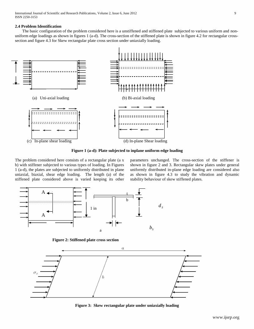
2.4 Problem Identification
The basic configuration of the problem considered here is a unstiffened and stiffened plate subjected to various uniform and non-
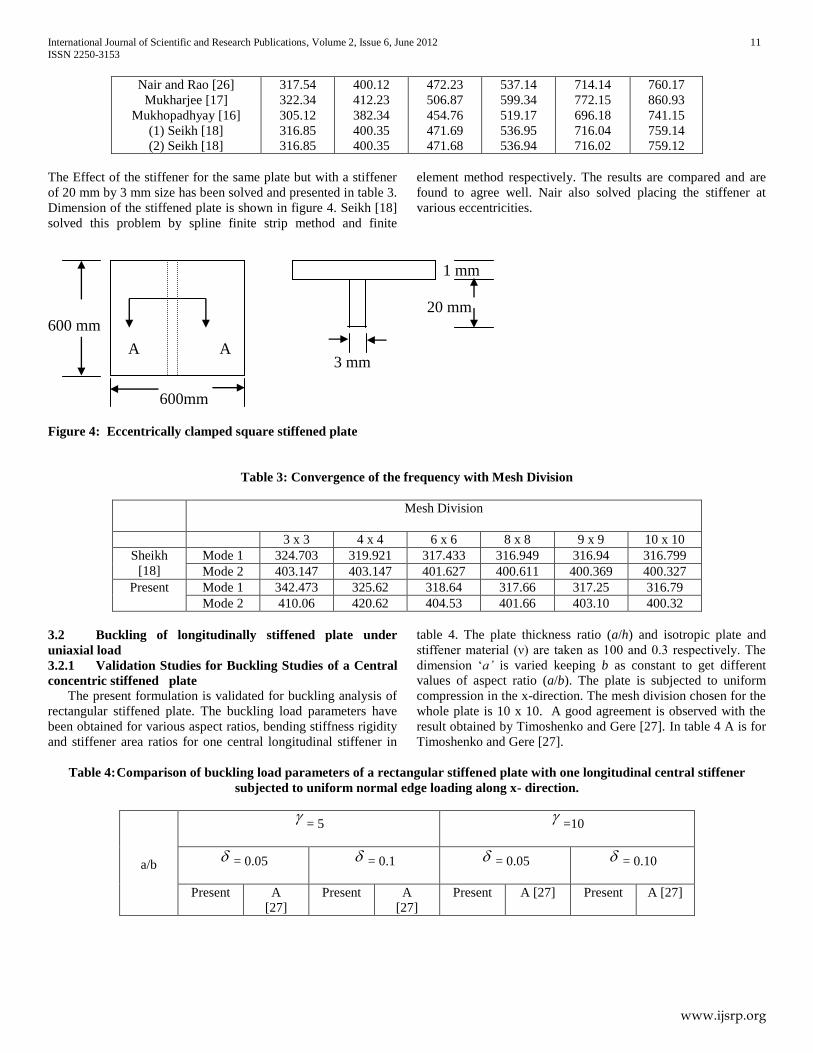
uniform edge loadings as shown in figures 1 (a-d). The cross-section of the stiffened plate is shown in figure 4.2 for rectangular cross-
section and figure 4.3 for Skew rectangular plate cross section under uniaxially loading.
b
c
a
(a) Uni-axial loading (b) Bi-axial loading
(c) In-plane shear loading (d) In-plane Shear loading
Figure 1 (a-d): Plate subjected to inplane uniform edge loading
The problem considered here consists of a rectangular plate (a x
b) with stiffener subjected to various types of loading. In Figures
1 (a-d), the plates are subjected to uniformly distributed in plane
uniaxial, biaxial, shear edge loading. The length (a) of the
stiffened plate considered above is varied keeping its other
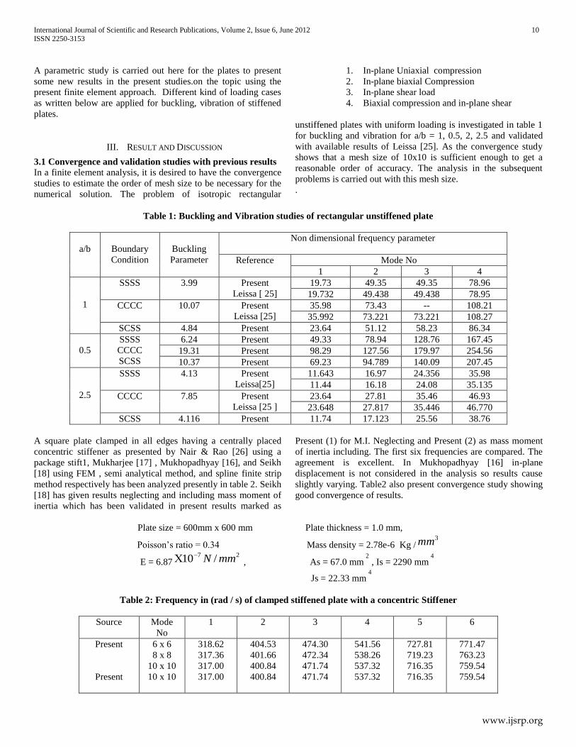
parameters unchanged. The cross-section of the stiffener is
shown in figure 2 and 3. Rectangular skew plates under general
uniformly distributed in-plane edge loading are considered also
as shown in figure 4.3 to study the vibration and dynamic
stability behaviour of skew stiffened plates.
t
b
1 in Sd
a Sb
Figure 2: Stiffened plate cross section
Figure 3: Skew rectangular plate under uniaxially loading
A
A
A
International Journal of Scientific and Research Publications, Volume 2, Issue 6, June 2012 10
ISSN 2250-3153
www.ijsrp.org
A parametric study is carried out here for the plates to present
some new results in the present studies.on the topic using the
present finite element approach. Different kind of loading cases
as written below are applied for buckling, vibration of stiffened
plates.
1. In-plane Uniaxial compression
2. In-plane biaxial Compression
3. In-plane shear load
4. Biaxial compression and in-plane shear
III. RESULT AND DISCUSSION
3.1 Convergence and validation studies with previous results
In a finite element analysis, it is desired to have the convergence
studies to estimate the order of mesh size to be necessary for the
numerical solution. The problem of isotropic rectangular
unstiffened plates with uniform loading is investigated in table 1
for buckling and vibration for a/b = 1, 0.5, 2, 2.5 and validated
with available results of Leissa [25]. As the convergence study
shows that a mesh size of 10x10 is sufficient enough to get a
reasonable order of accuracy. The analysis in the subsequent
problems is carried out with this mesh size.
.
Table 1: Buckling and Vibration studies of rectangular unstiffened plate
a/b
Boundary
Condition
Buckling
Parameter
Non dimensional frequency parameter
Reference Mode No
1 2 3 4
1
SSSS 3.99 Present
Leissa [ 25]
19.73 49.35 49.35 78.96
19.732 49.438 49.438 78.95
CCCC 10.07 Present
Leissa [25]
35.98 73.43 -- 108.21
35.992 73.221 73.221 108.27
SCSS 4.84 Present 23.64 51.12 58.23 86.34
0.5
SSSS
CCCC
SCSS
6.24 Present 49.33 78.94 128.76 167.45
19.31 Present 98.29 127.56 179.97 254.56
10.37 Present 69.23 94.789 140.09 207.45
2.5
SSSS 4.13 Present
Leissa[25]
11.643 16.97 24.356 35.98
11.44 16.18 24.08 35.135
CCCC 7.85 Present
Leissa [25 ]
23.64 27.81 35.46 46.93
23.648 27.817 35.446 46.770
SCSS 4.116 Present 11.74 17.123 25.56 38.76
A square plate clamped in all edges having a centrally placed
concentric stiffener as presented by Nair & Rao [26] using a
package stift1, Mukharjee [17] , Mukhopadhyay [16], and Seikh
[18] using FEM , semi analytical method, and spline finite strip
method respectively has been analyzed presently in table 2. Seikh
[18] has given results neglecting and including mass moment of
inertia which has been validated in present results marked as
Present (1) for M.I. Neglecting and Present (2) as mass moment
of inertia including. The first six frequencies are compared. The
agreement is excellent. In Mukhopadhyay [16] in-plane
displacement is not considered in the analysis so results cause
slightly varying. Table2 also present convergence study showing
good convergence of results.
Plate size = 600mm x 600 mm Plate thickness = 1.0 mm,
Poisson’s ratio = 0.34 Mass density = 2.78e-6 Kg /3mm
E = 6.8727 /10 mmN , As = 67.0 mm
2, Is = 2290 mm
4
Js = 22.33 mm4
Table 2: Frequency in (rad / s) of clamped stiffened plate with a concentric Stiffener
Source Mode
No
1 2 3 4 5 6
Present
Present
6 x 6
8 x 8
10 x 10
10 x 10
318.62
317.36
317.00
317.00
404.53
401.66
400.84
400.84
474.30
472.34
471.74
471.74
541.56
538.26
537.32
537.32
727.81
719.23
716.35
716.35
771.47
763.23
759.54
759.54
International Journal of Scientific and Research Publications, Volume 2, Issue 6, June 2012 11
ISSN 2250-3153
www.ijsrp.org
Nair and Rao [26]
Mukharjee [17]
Mukhopadhyay [16]
(1) Seikh [18]
(2) Seikh [18]
317.54
322.34
305.12
316.85
316.85
400.12
412.23
382.34
400.35
400.35
472.23
506.87
454.76
471.69
471.68
537.14
599.34
519.17
536.95
536.94
714.14
772.15
696.18
716.04
716.02
760.17
860.93
741.15
759.14
759.12
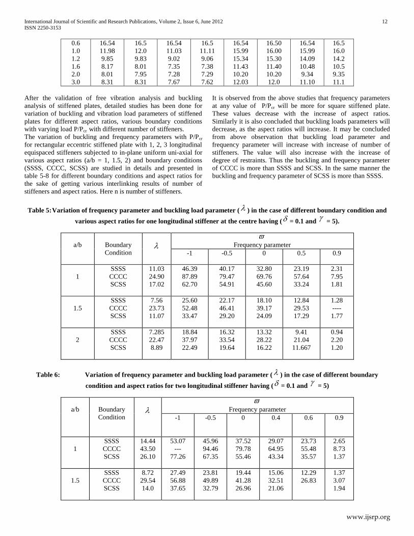
The Effect of the stiffener for the same plate but with a stiffener
of 20 mm by 3 mm size has been solved and presented in table 3.
Dimension of the stiffened plate is shown in figure 4. Seikh [18]
solved this problem by spline finite strip method and finite
element method respectively. The results are compared and are
found to agree well. Nair also solved placing the stiffener at
various eccentricities.
1 mm
20 mm
600 mm
AAA 3 mm
600mm
Figure 4: Eccentrically clamped square stiffened plate
Table 3: Convergence of the frequency with Mesh Division
Mesh Division
3 x 3 4 x 4 6 x 6 8 x 8 9 x 9 10 x 10
Sheikh
[18]
Mode 1 324.703 319.921 317.433 316.949 316.94 316.799
Mode 2 403.147 403.147 401.627 400.611 400.369 400.327
Present Mode 1 342.473 325.62 318.64 317.66 317.25 316.79
Mode 2 410.06 420.62 404.53 401.66 403.10 400.32
3.2 Buckling of longitudinally stiffened plate under
uniaxial load
3.2.1 Validation Studies for Buckling Studies of a Central
concentric stiffened plate The present formulation is validated for buckling analysis of
rectangular stiffened plate. The buckling load parameters have
been obtained for various aspect ratios, bending stiffness rigidity
and stiffener area ratios for one central longitudinal stiffener in
table 4. The plate thickness ratio (a/h) and isotropic plate and
stiffener material (ν) are taken as 100 and 0.3 respectively. The
dimension ‘a’ is varied keeping b as constant to get different
values of aspect ratio (a/b). The plate is subjected to uniform
compression in the x-direction. The mesh division chosen for the
whole plate is 10 x 10. A good agreement is observed with the
result obtained by Timoshenko and Gere [27]. In table 4 A is for
Timoshenko and Gere [27].
Table 4: Comparison of buckling load parameters of a rectangular stiffened plate with one longitudinal central stiffener
subjected to uniform normal edge loading along x- direction.
a/b
= 5
=10
= 0.05 = 0.1 = 0.05 = 0.10
Present A
[27]
Present A
[27]
Present A [27] Present A [27]
A A
International Journal of Scientific and Research Publications, Volume 2, Issue 6, June 2012 12
ISSN 2250-3153
www.ijsrp.org
0.6
1.0
1.2
1.6
2.0
3.0
16.54
11.98
9.85
8.17
8.01
8.31
16.5
12.0
9.83
8.01
7.95
8.31
16.54
11.03
9.02
7.35
7.28
7.67
16.5
11.11
9.06
7.38
7.29
7.62
16.54
15.99
15.34
11.43
10.20
12.03
16.50
16.00
15.30
11.40
10.20
12.0
16.54
15.99
14.09
10.48
9.34
11.10
16.5
16.0
14.2
10.5
9.35
11.1
After the validation of free vibration analysis and buckling
analysis of stiffened plates, detailed studies has been done for
variation of buckling and vibration load parameters of stiffened
plates for different aspect ratios, various boundary conditions
with varying load P/Pcr with different number of stiffeners.
The variation of buckling and frequency parameters with P/Pcr
for rectangular eccentric stiffened plate with 1, 2, 3 longitudinal
equispaced stiffeners subjected to in-plane uniform uni-axial for
various aspect ratios (a/b = 1, 1.5, 2) and boundary conditions
(SSSS, CCCC, SCSS) are studied in details and presented in
table 5-8 for different boundary conditions and aspect ratios for
the sake of getting various interlinking results of number of
stiffeners and aspect ratios. Here n is number of stiffeners.
It is observed from the above studies that frequency parameters
at any value of P/Pcr will be more for square stiffened plate.
These values decrease with the increase of aspect ratios.
Similarly it is also concluded that buckling loads parameters will
decrease, as the aspect ratios will increase. It may be concluded
from above observation that buckling load parameter and
frequency parameter will increase with increase of number of
stiffeners. The value will also increase with the increase of
degree of restraints. Thus the buckling and frequency parameter
of CCCC is more than SSSS and SCSS. In the same manner the
buckling and frequency parameter of SCSS is more than SSSS.
Table 5: Variation of frequency parameter and buckling load parameter ( ) in the case of different boundary condition and
various aspect ratios for one longitudinal stiffener at the centre having ( = 0.1 and
= 5).
a/b
Boundary
Condition
Frequency parameter
-1 -0.5 0 0.5 0.9
1
SSSS
CCCC
SCSS
11.03
24.90
17.02
46.39
87.89
62.70
40.17
79.47
54.91
32.80
69.76
45.60
23.19
57.64
33.24
2.31
7.95
1.81
1.5
SSSS
CCCC
SCSS
7.56
23.73
11.07
25.60
52.48
33.47
22.17
46.41
29.20
18.10
39.17
24.09
12.84
29.53
17.29
1.28
----
1.77
2
SSSS
CCCC
SCSS
7.285
22.47
8.89
18.84
37.97
22.49
16.32
33.54
19.64
13.32
28.22
16.22
9.41
21.04
11.667
0.94
2.20
1.20
Table 6: Variation of frequency parameter and buckling load parameter ( ) in the case of different boundary
condition and aspect ratios for two longitudinal stiffener having ( = 0.1 and
= 5)
a/b
Boundary
Condition
Frequency parameter
-1 -0.5 0 0.4 0.6 0.9
1
SSSS
CCCC
SCSS
14.44
43.50
26.10
53.07
---
77.26
45.96
94.46
67.35
37.52
79.78
55.46
29.07
64.95
43.34
23.73
55.48
35.57
2.65
8.73
1.37
1.5
SSSS
CCCC
SCSS
8.72
29.54
14.0
27.49
56.88
37.65
23.81
49.89
32.79
19.44
41.28
26.96
15.06
32.51
21.06
12.29
26.83
1.37
3.07
1.94
International Journal of Scientific and Research Publications, Volume 2, Issue 6, June 2012 13
ISSN 2250-3153
www.ijsrp.org
2
SSSS
CCCC
SCSS
7.68
25.11
10.27
19.35
39.46
24.18
16.79
34.64
21.07
13.69
28.81
17.35
10.60
22.80
13.56
8.66
18.89
11.13
0.96
2.18
1.26
Table 7: Variation of frequency parameter and buckling load parameter ( ) in the case of different boundary condition and
aspect ratios for three longitudinal stiffener having ( = 0.1 and
= 5).
a/b
BoundaryC
ondition
Frequency parameter
-1 -0.5 0 0.4 0.6 0.9
1
SSSS
CCCC
SCSS
17.04
60.64
32.08
57.67
---
85.63
49.94
---
74.55
40.78
88.85
61.27
31.58
69.93
47.76
25.79
57.79
39.15
2.88
6.61
4.41
1.5
SSSS
CCCC
SCSS
9.69
34.12
16.30
28.97
60.95
40.63
25.09
53.25
35.37
20.49
43.95
29.05
15.87
34.42
22.64
12.96
28.29
18.36
1.45
3.20
2. 09
2
SSSS
CCCC
SCSS
8.03
27.2
11.38
19.78
40.92
25.46
17.13
35.82
22.18
14
29.67
18.24
10.83
23.35
14.24
8.85
19.25
11.68
0.99
2.19
1.32
Table 8: Variation of frequency parameter and buckling load parameter ( ) for stiffened plate (Equispaced, one stiffener, two
stiffener, three stiffener) with different aspect ratio and boundary condition having ( = 0.1,
= 5)
No of Stiffener
1 2 3
a/b
Boundary
Condition
1
SSSS
CCCC
SCSS
11.03
24.90
17.02
32.80
69.76
45.60
14.40
43.50
26.70
37.52
79.78
55.46
17.04
60.64
32.08
40.78
88.85
61.25
2
SSSS
CCCC
SCSS
7.285
22.47
8.89
13.32
28.22
16.22
7.68
25.11
10.27
13.69
28.81
17.35
8.03
27.2
11.38
14.00
29.67
18.24
1.5
SSSS
CCCC
SCSS
7.56
23.73
11.07
18.10
39.17
24.09
8.72
29.54
14.03
19.44
41.28
26.96
9.69
34.12
16.30
20.49
43.95
29.05
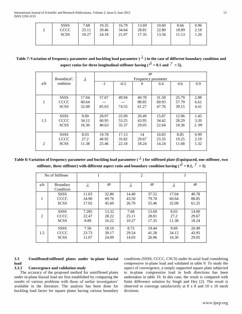
3.3 Unstiffened/stiffened plates under in-plane biaxial
load
3.3.1 Convergence and validation study
The accuracy of the proposed method for unstiffened plates
under in-plane biaxial load are first established by comparing the
results of various problems with those of earlier investigators’
available in the literature. The analysis has been done for
buckling load factor for square plates having various boundary
conditions (SSSS, CCCC, CSCS) under bi-axial load considering
compressive in-plane load and validated in table 9. To study the
aspect of convergence, a simply supported square plate subjected
to in-plane compressive load in both directions has been
undertaken in table 10. In this case, the result is compared with
finite difference solution by Singh and Dey [2]. The result is
observed to converge satisfactorily at 8 x 8 and 10 x 10 mesh
divisions.
International Journal of Scientific and Research Publications, Volume 2, Issue 6, June 2012 14
ISSN 2250-3153
www.ijsrp.org
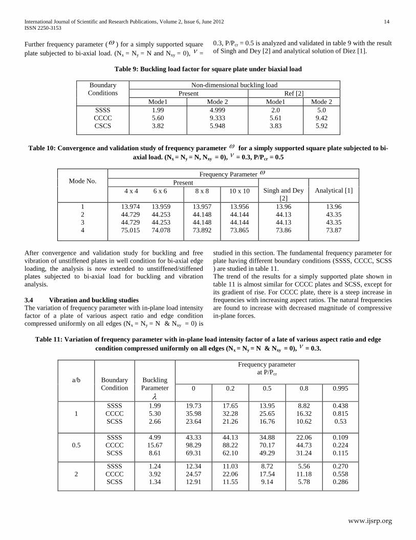
Further frequency parameter ( ) for a simply supported square
plate subjected to bi-axial load. (Nx = Ny = N and Nxy = 0), =
0.3, P/Pcr = 0.5 is analyzed and validated in table 9 with the result
of Singh and Dey [2] and analytical solution of Diez [1].
Table 9: Buckling load factor for square plate under biaxial load
Boundary
Conditions
Non-dimensional buckling load
Present Ref [2]
Mode1 Mode 2 Mode1 Mode 2
SSSS
CCCC
CSCS
1.99
5.60
3.82
4.999
9.333
5.948
2.0
5.61
3.83
5.0
9.42
5.92
Table 10: Convergence and validation study of frequency parameter for a simply supported square plate subjected to bi-
axial load. (Nx = Ny = N, Nxy = 0), = 0.3, P/Pcr = 0.5
Mode No. Frequency Parameter
Present
Singh and Dey
[2]
Analytical [1]
4 x 4 6 x 6 8 x 8 10 x 10
1
2
3
4
13.974 13.959
44.729 44.253
44.729 44.253
75.015 74.078
13.957
44.148
44.148
73.892
13.956
44.144
44.144
73.865
13.96
44.13
44.13
73.86
13.96
43.35
43.35
73.87
After convergence and validation study for buckling and free
vibration of unstiffened plates in well condition for bi-axial edge
loading, the analysis is now extended to unstiffened/stiffened
plates subjected to bi-axial load for buckling and vibration
analysis.
3.4 Vibration and buckling studies
The variation of frequency parameter with in-plane load intensity
factor of a plate of various aspect ratio and edge condition
compressed uniformly on all edges (Nx = Ny = N & Nxy = 0) is
studied in this section. The fundamental frequency parameter for
plate having different boundary conditions (SSSS, CCCC, SCSS
) are studied in table 11.
The trend of the results for a simply supported plate shown in
table 11 is almost similar for CCCC plates and SCSS, except for
its gradient of rise. For CCCC plate, there is a steep increase in
frequencies with increasing aspect ratios. The natural frequencies
are found to increase with decreased magnitude of compressive
in-plane forces.
Table 11: Variation of frequency parameter with in-plane load intensity factor of a late of various aspect ratio and edge
condition compressed uniformly on all edges (Nx = Ny = N & Nxy = 0), = 0.3.
a/b
Boundary
Condition
Buckling
Parameter
Frequency parameter
at P/Pcr
0 0.2 0.5 0.8 0.995
1
SSSS
CCCC
SCSS
1.99
5.30
2.66
19.73
35.98
23.64
17.65
32.28
21.26
13.95
25.65
16.76
8.82
16.32
10.62
0.438
0.815
0.53
0.5
SSSS
CCCC
SCSS
4.99
15.67
8.61
43.33
98.29
69.31
44.13
88.22
62.10
34.88
70.17
49.29
22.06
44.73
31.24
0.109
0.224
0.115
2
SSSS
CCCC
SCSS
1.24
3.92
1.34
12.34
24.57
12.91
11.03
22.06
11.55
8.72
17.54
9.14
5.56
11.18
5.78
0.270
0.558
0.286
International Journal of Scientific and Research Publications, Volume 2, Issue 6, June 2012 15
ISSN 2250-3153
www.ijsrp.org
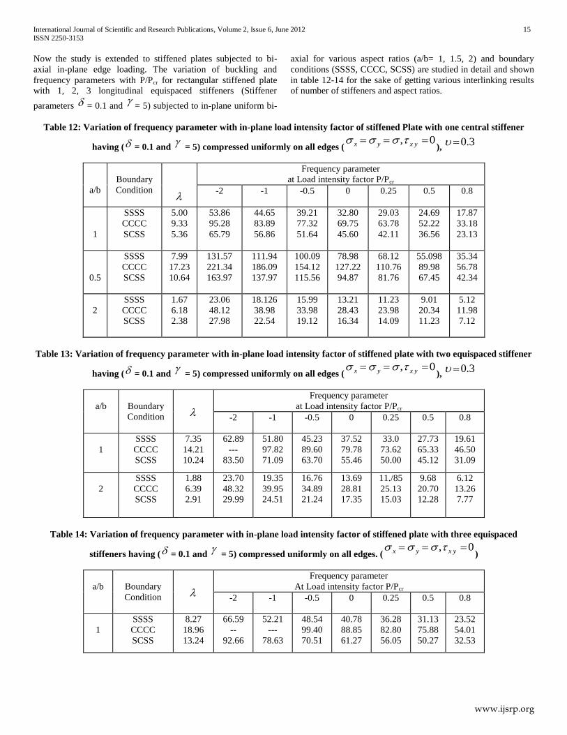
Now the study is extended to stiffened plates subjected to bi-
axial in-plane edge loading. The variation of buckling and
frequency parameters with P/Pcr for rectangular stiffened plate
with 1, 2, 3 longitudinal equispaced stiffeners (Stiffener
parameters = 0.1 and
= 5) subjected to in-plane uniform bi-
axial for various aspect ratios (a/b= 1, 1.5, 2) and boundary
conditions (SSSS, CCCC, SCSS) are studied in detail and shown
in table 12-14 for the sake of getting various interlinking results
of number of stiffeners and aspect ratios.
Table 12: Variation of frequency parameter with in-plane load intensity factor of stiffened Plate with one central stiffener
having ( = 0.1 and
= 5) compressed uniformly on all edges (0, yxyx
), 3.0
a/b
Boundary
Condition
Frequency parameter
at Load intensity factor P/Pcr
-2 -1 -0.5 0 0.25 0.5 0.8
1
SSSS
CCCC
SCSS
5.00
9.33
5.36
53.86
95.28
65.79
44.65
83.89
56.86
39.21
77.32
51.64
32.80
69.75
45.60
29.03
63.78
42.11
24.69
52.22
36.56
17.87
33.18
23.13
0.5
SSSS
CCCC
SCSS
7.99
17.23
10.64
131.57
221.34
163.97
111.94
186.09
137.97
100.09
154.12
115.56
78.98
127.22
94.87
68.12
110.76
81.76
55.098
89.98
67.45
35.34
56.78
42.34
2
SSSS
CCCC
SCSS
1.67
6.18
2.38
23.06
48.12
27.98
18.126
38.98
22.54
15.99
33.98
19.12
13.21
28.43
16.34
11.23
23.98
14.09
9.01
20.34
11.23
5.12
11.98
7.12
Table 13: Variation of frequency parameter with in-plane load intensity factor of stiffened plate with two equispaced stiffener
having ( = 0.1 and
= 5) compressed uniformly on all edges (0, yxyx
), 3.0
a/b
Boundary
Condition
Frequency parameter
at Load intensity factor P/Pcr
-2 -1 -0.5 0 0.25 0.5 0.8
1
SSSS
CCCC
SCSS
7.35
14.21
10.24
62.89
---
83.50
51.80
97.82
71.09
45.23
89.60
63.70
37.52
79.78
55.46
33.0
73.62
50.00
27.73
65.33
45.12
19.61
46.50
31.09
2
SSSS
CCCC
SCSS
1.88
6.39
2.91
23.70
48.32
29.99
19.35
39.95
24.51
16.76
34.89
21.24
13.69
28.81
17.35
11./85
25.13
15.03
9.68
20.70
12.28
6.12
13.26
7.77
Table 14: Variation of frequency parameter with in-plane load intensity factor of stiffened plate with three equispaced
stiffeners having ( = 0.1 and
= 5) compressed uniformly on all edges. (0, yxyx
)
a/b
Boundary
Condition
Frequency parameter
At Load intensity factor P/Pcr
-2 -1 -0.5 0 0.25 0.5 0.8
1
SSSS
CCCC
SCSS
8.27
18.96
13.24
66.59
--
92.66
52.21
---
78.63
48.54
99.40
70.51
40.78
88.85
61.27
36.28
82.80
56.05
31.13
75.88
50.27
23.52
54.01
32.53
International Journal of Scientific and Research Publications, Volume 2, Issue 6, June 2012 16
ISSN 2250-3153
www.ijsrp.org
2
SSSS
CCCC
SCSS
2.08
7.19
3.39
24.42
49.84
31.53
19.78
41.18
25.77
17.13
35.96
22.33
13.99
29.67
18.24
12.11
25.87
15.80
9.89
21.29
12.91
6.26
13.69
8.17
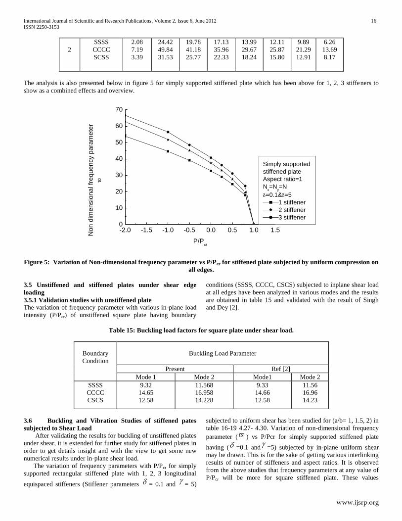
The analysis is also presented below in figure 5 for simply supported stiffened plate which has been above for 1, 2, 3 stiffeners to
show as a combined effects and overview.
-2.0 -1.5 -1.0 -0.5 0.0 0.5 1.0 1.50
10
20
30
40
50
60
70
Non d
imensio
nal fr
equency p
ara
mete
r
P/Pcr
Simply supported
stiffened plate
Aspect ratio=1
Nx=N
y=N
=0.1&=5
1 stiffener
2 stiffener
3 stiffener
Figure 5: Variation of Non-dimensional frequency parameter vs P/Pcr for stiffened plate subjected by uniform compression on
all edges.
3.5 Unstiffened and stiffened plates uunder shear edge
loading
3.5.1 Validation studies with unstiffened plate
The variation of frequency parameter with various in-plane load
intensity (P/Pcr) of unstiffened square plate having boundary
conditions (SSSS, CCCC, CSCS) subjected to inplane shear load
at all edges have been analyzed in various modes and the results
are obtained in table 15 and validated with the result of Singh
and Dey [2].
Table 15: Buckling load factors for square plate under shear load.
Boundary
Condition
Buckling Load Parameter
Present Ref [2]
Mode 1 Mode 2 Mode1 Mode 2
SSSS
CCCC
CSCS
9.32
14.65
12.58
11.568
16.958
14.228
9.33
14.66
12.58
11.56
16.96
14.23
3.6 Buckling and Vibration Studies of stiffened pates
subjected to Shear Load
After validating the results for buckling of unstiffened plates
under shear, it is extended for further study for stiffened plates in
order to get details insight and with the view to get some new
numerical results under in-plane shear load.
The variation of frequency parameters with P/Pcr for simply
supported rectangular stiffened plate with 1, 2, 3 longitudinal
equispaced stiffeners (Stiffener parameters = 0.1 and
= 5)
subjected to uniform shear has been studied for (a/b= 1, 1.5, 2) in
table 16-19 4.27- 4.30. Variation of non-dimensional frequency
parameter ( ) vs P/Pcr for simply supported stiffened plate
having ( =0.1 and
=5) subjected by in-plane uniform shear
may be drawn. This is for the sake of getting various interlinking
results of number of stiffeners and aspect ratios. It is observed
from the above studies that frequency parameters at any value of
P/Pcr will be more for square stiffened plate. These values
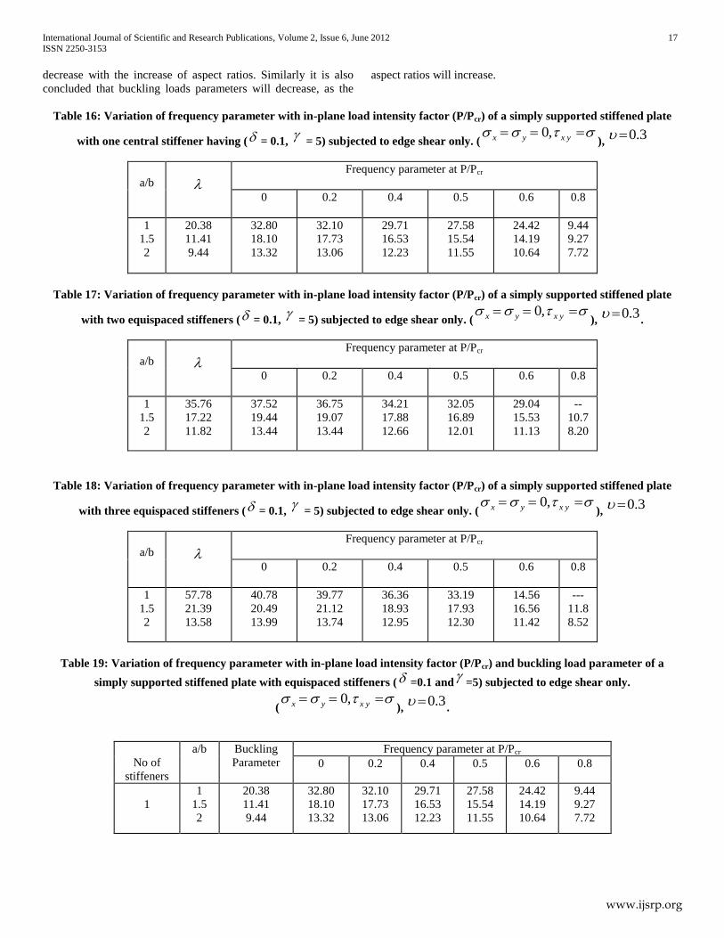
International Journal of Scientific and Research Publications, Volume 2, Issue 6, June 2012 17
ISSN 2250-3153
www.ijsrp.org
decrease with the increase of aspect ratios. Similarly it is also
concluded that buckling loads parameters will decrease, as the
aspect ratios will increase.
Table 16: Variation of frequency parameter with in-plane load intensity factor (P/Pcr) of a simply supported stiffened plate
with one central stiffener having ( = 0.1,
= 5) subjected to edge shear only. ( yxyx ,0
), 3.0
a/b
Frequency parameter at P/Pcr
0 0.2 0.4 0.5 0.6 0.8
1
1.5
2
20.38
11.41
9.44
32.80
18.10
13.32
32.10
17.73
13.06
29.71
16.53
12.23
27.58
15.54
11.55
24.42
14.19
10.64
9.44
9.27
7.72
Table 17: Variation of frequency parameter with in-plane load intensity factor (P/Pcr) of a simply supported stiffened plate
with two equispaced stiffeners ( = 0.1,
= 5) subjected to edge shear only. ( yxyx ,0
), 3.0
.
a/b
Frequency parameter at P/Pcr
0 0.2 0.4 0.5 0.6 0.8
1
1.5
2
35.76
17.22
11.82
37.52
19.44
13.44
36.75
19.07
13.44
34.21
17.88
12.66
32.05
16.89
12.01
29.04
15.53
11.13
--
10.7
8.20
Table 18: Variation of frequency parameter with in-plane load intensity factor (P/Pcr) of a simply supported stiffened plate
with three equispaced stiffeners ( = 0.1,
= 5) subjected to edge shear only. ( yxyx ,0
), 3.0
a/b
Frequency parameter at P/Pcr
0 0.2 0.4 0.5 0.6 0.8
1
1.5
2
57.78
21.39
13.58
40.78
20.49
13.99
39.77
21.12
13.74
36.36
18.93
12.95
33.19
17.93
12.30
14.56
16.56
11.42
---
11.8
8.52
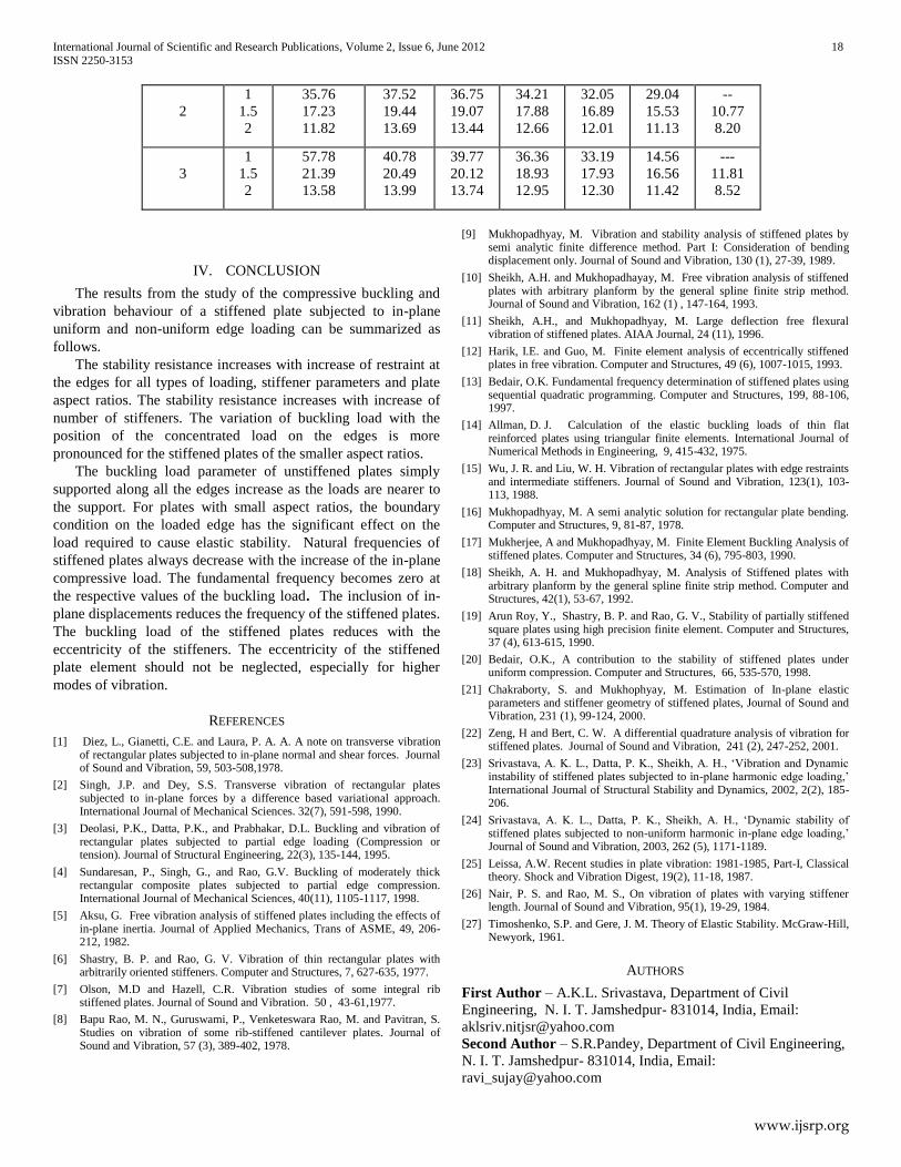
Table 19: Variation of frequency parameter with in-plane load intensity factor (P/Pcr) and buckling load parameter of a
simply supported stiffened plate with equispaced stiffeners ( =0.1 and
=5) subjected to edge shear only.
( yxyx ,0
), 3.0
.
No of
stiffeners
a/b Buckling
Parameter
Frequency parameter at P/Pcr
0 0.2 0.4 0.5 0.6 0.8
1
1
1.5
2
20.38
11.41
9.44
32.80
18.10
13.32
32.10
17.73
13.06
29.71
16.53
12.23
27.58
15.54
11.55
24.42
14.19
10.64
9.44
9.27
7.72
International Journal of Scientific and Research Publications, Volume 2, Issue 6, June 2012 18
ISSN 2250-3153
www.ijsrp.org
2
1
1.5
2
35.76
17.23
11.82
37.52
19.44
13.69
36.75
19.07
13.44
34.21
17.88
12.66
32.05
16.89
12.01
29.04
15.53
11.13
--
10.77
8.20
3
1
1.5
2
57.78
21.39
13.58
40.78
20.49
13.99
39.77
20.12
13.74
36.36
18.93
12.95
33.19
17.93
12.30
14.56
16.56
11.42
---
11.81
8.52
IV. CONCLUSION
The results from the study of the compressive buckling and
vibration behaviour of a stiffened plate subjected to in-plane
uniform and non-uniform edge loading can be summarized as
follows.
The stability resistance increases with increase of restraint at
the edges for all types of loading, stiffener parameters and plate
aspect ratios. The stability resistance increases with increase of
number of stiffeners. The variation of buckling load with the
position of the concentrated load on the edges is more
pronounced for the stiffened plates of the smaller aspect ratios.
The buckling load parameter of unstiffened plates simply
supported along all the edges increase as the loads are nearer to
the support. For plates with small aspect ratios, the boundary
condition on the loaded edge has the significant effect on the
load required to cause elastic stability. Natural frequencies of
stiffened plates always decrease with the increase of the in-plane
compressive load. The fundamental frequency becomes zero at
the respective values of the buckling load. The inclusion of in-
plane displacements reduces the frequency of the stiffened plates.
The buckling load of the stiffened plates reduces with the
eccentricity of the stiffeners. The eccentricity of the stiffened
plate element should not be neglected, especially for higher
modes of vibration.
REFERENCES
[1] Diez, L., Gianetti, C.E. and Laura, P. A. A. A note on transverse vibration of rectangular plates subjected to in-plane normal and shear forces. Journal of Sound and Vibration, 59, 503-508,1978.
[2] Singh, J.P. and Dey, S.S. Transverse vibration of rectangular plates subjected to in-plane forces by a difference based variational approach. International Journal of Mechanical Sciences. 32(7), 591-598, 1990.
[3] Deolasi, P.K., Datta, P.K., and Prabhakar, D.L. Buckling and vibration of rectangular plates subjected to partial edge loading (Compression or tension). Journal of Structural Engineering, 22(3), 135-144, 1995.
[4] Sundaresan, P., Singh, G., and Rao, G.V. Buckling of moderately thick rectangular composite plates subjected to partial edge compression. International Journal of Mechanical Sciences, 40(11), 1105-1117, 1998.
[5] Aksu, G. Free vibration analysis of stiffened plates including the effects of in-plane inertia. Journal of Applied Mechanics, Trans of ASME, 49, 206-212, 1982.
[6] Shastry, B. P. and Rao, G. V. Vibration of thin rectangular plates with arbitrarily oriented stiffeners. Computer and Structures, 7, 627-635, 1977.
[7] Olson, M.D and Hazell, C.R. Vibration studies of some integral rib stiffened plates. Journal of Sound and Vibration. 50 , 43-61,1977.
[8] Bapu Rao, M. N., Guruswami, P., Venketeswara Rao, M. and Pavitran, S. Studies on vibration of some rib-stiffened cantilever plates. Journal of Sound and Vibration, 57 (3), 389-402, 1978.
[9] Mukhopadhyay, M. Vibration and stability analysis of stiffened plates by semi analytic finite difference method. Part I: Consideration of bending displacement only. Journal of Sound and Vibration, 130 (1), 27-39, 1989.
[10] Sheikh, A.H. and Mukhopadhayay, M. Free vibration analysis of stiffened plates with arbitrary planform by the general spline finite strip method. Journal of Sound and Vibration, 162 (1) , 147-164, 1993.
[11] Sheikh, A.H., and Mukhopadhyay, M. Large deflection free flexural vibration of stiffened plates. AIAA Journal, 24 (11), 1996.
[12] Harik, I.E. and Guo, M. Finite element analysis of eccentrically stiffened plates in free vibration. Computer and Structures, 49 (6), 1007-1015, 1993.
[13] Bedair, O.K. Fundamental frequency determination of stiffened plates using sequential quadratic programming. Computer and Structures, 199, 88-106, 1997.
[14] Allman, D. J. Calculation of the elastic buckling loads of thin flat reinforced plates using triangular finite elements. International Journal of Numerical Methods in Engineering, 9, 415-432, 1975.
[15] Wu, J. R. and Liu, W. H. Vibration of rectangular plates with edge restraints and intermediate stiffeners. Journal of Sound and Vibration, 123(1), 103-113, 1988.
[16] Mukhopadhyay, M. A semi analytic solution for rectangular plate bending. Computer and Structures, 9, 81-87, 1978.
[17] Mukherjee, A and Mukhopadhyay, M. Finite Element Buckling Analysis of stiffened plates. Computer and Structures, 34 (6), 795-803, 1990.
[18] Sheikh, A. H. and Mukhopadhyay, M. Analysis of Stiffened plates with arbitrary planform by the general spline finite strip method. Computer and Structures, 42(1), 53-67, 1992.
[19] Arun Roy, Y., Shastry, B. P. and Rao, G. V., Stability of partially stiffened square plates using high precision finite element. Computer and Structures, 37 (4), 613-615, 1990.
[20] Bedair, O.K., A contribution to the stability of stiffened plates under uniform compression. Computer and Structures, 66, 535-570, 1998.
[21] Chakraborty, S. and Mukhophyay, M. Estimation of In-plane elastic parameters and stiffener geometry of stiffened plates, Journal of Sound and Vibration, 231 (1), 99-124, 2000.
[22] Zeng, H and Bert, C. W. A differential quadrature analysis of vibration for stiffened plates. Journal of Sound and Vibration, 241 (2), 247-252, 2001.
[23] Srivastava, A. K. L., Datta, P. K., Sheikh, A. H., ‘Vibration and Dynamic instability of stiffened plates subjected to in-plane harmonic edge loading,’ International Journal of Structural Stability and Dynamics, 2002, 2(2), 185-206.
[24] Srivastava, A. K. L., Datta, P. K., Sheikh, A. H., ‘Dynamic stability of stiffened plates subjected to non-uniform harmonic in-plane edge loading,’ Journal of Sound and Vibration, 2003, 262 (5), 1171-1189.
[25] Leissa, A.W. Recent studies in plate vibration: 1981-1985, Part-I, Classical theory. Shock and Vibration Digest, 19(2), 11-18, 1987.
[26] Nair, P. S. and Rao, M. S., On vibration of plates with varying stiffener length. Journal of Sound and Vibration, 95(1), 19-29, 1984.
[27] Timoshenko, S.P. and Gere, J. M. Theory of Elastic Stability. McGraw-Hill, Newyork, 1961.
AUTHORS
First Author – A.K.L. Srivastava, Department of Civil
Engineering, N. I. T. Jamshedpur- 831014, India, Email:
Second Author – S.R.Pandey, Department of Civil Engineering,
N. I. T. Jamshedpur- 831014, India, Email: