Embed Size (px)
Citation preview
HOUSEL
Behavior of a Rotor
in a Two-Phase Field
Electrical Engineering
B. S. 4 " J* :
'
>-
1901
UNJVEKi'ITVOF
TU-. UBRAM
+ ****** I § I* * * * * * * * * * mmm * * * *\s-<Wimmm lIKf * * * * # ^ * * # *****,************
jf| * * * "SiHr 1toW* *' *
#* * * * * * * * 1 1 I
;
I . I I I |p |i
* i al # * lllifl 4 1 I 1 i I H* * ^ # * * * f + * # * * + + • * ^
^mmmm^m^^m* \ 1 MiSilBH 1 #; ;
* IBf F # # # f
t ^ T * * f"
I §
* * * *
* # # #* f«
air- . j£
****** *##*.#'^ .a #• # # 4. 4: •# 4* #
ir w w 1framing anb $Tabor
LIBRARYOF THE
# University of Illinois.|
^CI,A|. BOOK. VOLUME.
TF ~ 3F
'
4.' * 4 1 A\:W W W IF
*r ^ W
****** yao'l =»h*\at Jt A tr r
TP "T T-
# # ih f*
^ ^ ^# #= *r # 1r ^ * ^ ^ ^* Jk^:
*6 >Xl *A at JL ^ -de Jl ' & d
f* ^ * ^ ^ ^ ^ $ ^ ^ ^ ^ ^ ^ ^ ^
I
Accession No.
^. j!
^ jt 4. ^
.* * * * -1* * * * 4r 4 f************** * * * ^ T
J^f '^i^l
*
mm
# ^ ^
#i
4

V J
-- ;v
'
:
- =^ '
<*, j
* : T IF--- . f
-
• W' * '^li^"!/^r"-"-.:.' /-^r' • ^ T
Ilb
if
^* * * #

Digitized by the Internet Archive
in 2013
http://archive.org/details/behaviorofrotoriOOhous
BEHAVIOR CP A ROTOR IN A TWO-PHASE FIELD.
By 0. L. Housel.
THESIS FOR THE DEGREE OF BACHELOR OF SCIENCE IN
ELK CTR I CAL ENG 1 1 IEER IN
G
in the
COLLEGE OF ENGINEERING
UNIVERSITY OF ILLINOIS.
Presented JUNE, 1901.

tf'SA
UNIVERSITY OF ILLINOIS
May 31, 1901 190
THIS IS TO CERTIFY THAT THE THESIS PREPARED UNDER MY SUPERVISION BY
Oboar Lloyd PIousel
Behavior of a Rotor in a Two-Phase Field
IS APPROVED BY ME AS FULFILLING THIS PART OF THE REQUIREMENTS FOR THE DEGREE
Bachelor of Science in Electrical Engineering.
>
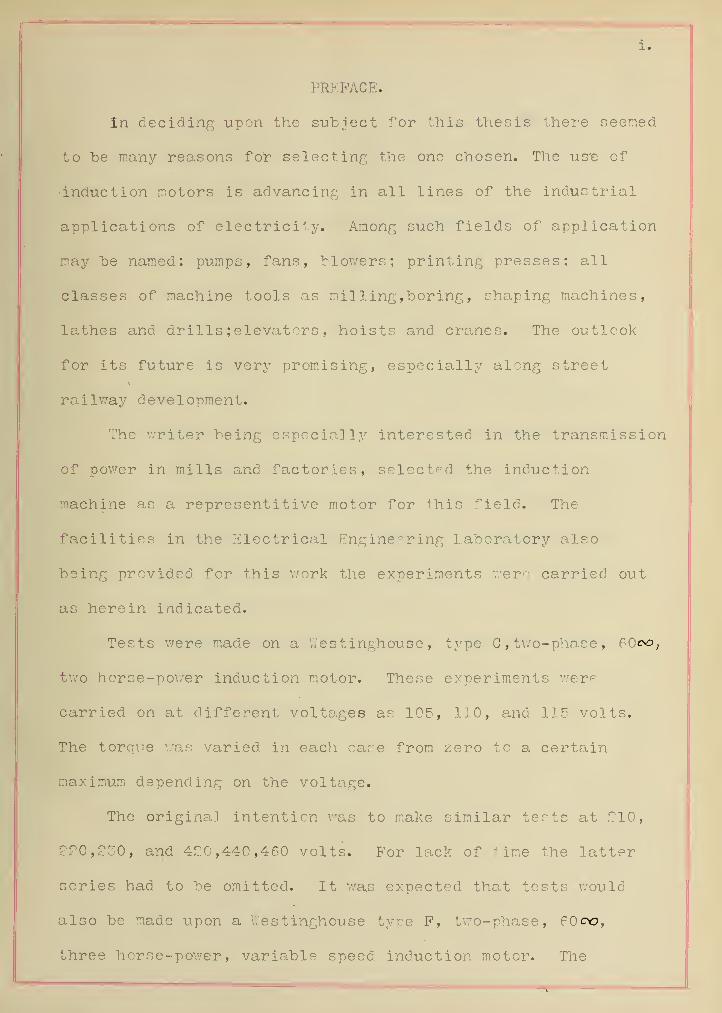
PREFACE.
In deciding upon the subject for this thesis there seemed
to "be many reasons for selecting the one chosen. The use of
•induction motors is advancing in all lines of the industrial
applications of electricity. Among such fields of application
may be named: pumps, fans, blowers; printing presses; all
classes of machine tools as milling,boring, shaping machines,
lathes and drills ; elevators , hoists and cranes. The outlook
for its future is very promising, especially along street
railway development.
The writer being especially interested in the transmission
of power in mills and factories, selected the induction
machine as a representi tive motor for this field. The
facilities in the Electrical Engineering Laboratory also
being provided for this work the experiments were carried out
as herein indicated.
Tests were made on a V/estinghouse , type C, two-phase, 60oo;
two horse-power induction motor. These experiments were
carried on at different voltages as 105, 110, and 115 volts.
The torque was varied in each case from zero to a certain
maximum depending on the voltage.
The original intention was to make similar tests at 210,
220, £30, and 420,440,460 volts. For lack of time the latter
series had to be omitted. It was expected that tests would
also be made upon a V.'es tinghouse type P, two-phase, 60c>o,
three horse-power, variable speed induction motor. The

manufacturers were unable to ship this motor in time to "begin
the experiments.
In conclusion it may be said of the thesis investigations
•carried out as shown in the following pages:
(1.) Extremely light weight, 250 pounds rated, for maximum
power which it was found capable of developing,
3.4 Kilo Watts at 115 volts.
(2.) The slip was, at normal rated load, about 6 1/2
per cent.
(3.) Under all conditions of the trials with various
impressed voltages the starting torque was in excess
of that usually allowed for machines of this size.
(4. ) The real efficiency showed a high maintained value
of about 80 per cent, in general for a wide range of
load, from about 50 per cent, underload to about
25 per cent overload.
(5.^ The power factor showed a satisfactory maintained
value of about 85 per cent, from about full load to
maximum overload.

iii.
SYLLABUS.
INDUCTION MOTORS.
I. ^DEVELOPMENT OF THE INDUCTION MOTOR.
1 . -Production of rotary or rotating magnetic fields; 1, 2,
or ^-phase.
2. -Interaction of magnetic field upon its induced current in
conductor.
Spinning disks Bahbage, Arago, Faraday ; wattmeter disk.
Eddy currents in spinning disks of copper and aluminium
Eddy currents in copper or aluminium cylinder,
continuous or split, as the rotor of the induction
motor, of squirrel-cage type.
3. -Early types of induction motors:l, 2, and 3-phase.
4. -Example of principles of induction motor in wattmeters.
II. -THKORY AND PRINCIPLES.
1. -General principles underlying action of induction motor.
2. -Relation of induction motor,general and as two-phase :
-
(a.) to the alternating current transformer,
(b) to the direct current shunt motor.
3. -Theory and principles of special types of induction motors.
Single-phase :Brown,l.'agner ; Two-phase , Ferraris ,Tesla;
Three-phase, General Electric.
III. -CLASSIFICATION.
1. -General: Rotary induction apparatus which consists of
primary and secondary windings , rotating with respect

to each other, comprising:
(a) Induction motors.
(b) Induction generators.
(c) Frequency changers.
(d) Rotary phase converters.
-Induction motors with variable resistance in armature or
rotor.
-Induction motors with short-circuited armatures, squirrel-
cage rotors.
IV. -ELEMENTS OF DESIGN.
-Allowances, constants and coefficients.
(a) Leakage, leakage factor and air gap.
(b) Inductance of s tat or and rotor.
(c) Core losses, hystersis and eddy currents.
f R(d) Copper losses: Equivalent resistance — —'— for
calculating copper losses: value of this method:
dependance on voltage, load, frequency, etc.
Electric and magnetic circuits of machine.
Mechanical and structural details.
V. -CONSTRUCTION.
Electrical details, windings, diagrams, insulation, etc.
Magnetic considerations, lamination of cores, balance of
rotor.
Mechanical and structural details; static and dynamic
balance of rotor.
Description of induction motors in commercial use.

V.
5 . -Accesoriee
:
Phase-splitting devices for single phase motors;
Starting and switching-in arrangements, compensators.
Variable speed control, multi-speed motors.
Use of resistance, induction and capacity in starting
and in control.
VI. - INSPECT I OK.
1 . -Mechanical , electrical, and magnetic.
VII. -OPERATION.
1 . -Starting : effect and value of starting devices ; torque
,
current.
2 . -Functional working; normal and overload conditions.
3. -Effect of varying the impressed E. L. F. , on starting and
operation loaded.
4. -Cacpac ty of 2- and 3-phase machines operated single-phase.
5. -Reversal Of 2- and 3-phase motors.
6 . -Faulty working and remedies.
7. -Influence of frequency , speed and slip ; variable speed
performance.
8. -Regulation, control of vol tage ; effect on lighting circuits.
VIII. -PERFORMANCE AND TESTING.
1 . -Principles and methods employed : electrical , magnetic , and
mechanical.
2. -Errors,precautions , precision of measurements.
3. -Effect of variables on performance : voltage , frequency
,
phase shifting.

Functional performance : characteristics , losses , efficiency.
Starting performance , start ing and crossing devices:
current, torque, etc.
Electrical characteristics of performance: current ,E.L. F. ,
power and power factor, true and apparent efficiency,
torque efficiency, phase difference , idle or "wattless"
energy.(a) Losses , determination and separation of.
(b) Impressed E. M. P. - dependence upon of speed,
maximum torque, slip, power, power factor , efficiencies
and various losses.
(c) Frequency,- dependence upon, of speed, maximum
torque, slip, power, power factor, efficiency and
various losses.
(d) Current values: magnetizing current, idle or
"wattless" current , starting cutrent , induced rotor
currents.
Magnetic determinations: indue t ion, leakage , leakage factor,
air gap, core losses.
Performance,general characteristics of,- electrical,
magnetic, mechanical.
(a) Deductions and conclusion from behavior performance
and test.
(b) Do results of test corroborate principles of
action and constants used in designs?

vii.
IX. -SPECIAL STUDIES OF INDUCTION MOTORS.
1. -Analysis of action of induction motor, application of
diagrams , etc.
2. -Establishment of laws of induction motor, electrical,
magnetic, and mechanical.
3. -Phase splitting and phase splitting devices.
4. -Induct ion motor or an induction generator.
5 . -Concatenation of induction motors.
6. -Induction motors as frequency changing transformer.
7. -Influence of wave form upon iron losses.

vii i.
BEHAVIOR OP A ROTOR IN A TWO-PHASE FIELD.
TABLE OF CONTENTS.
CHAPTER I*
• DEVELOPMENT OF THE TWO-PHASE INDUCTION MOTOR.
Article. Page,
1. Production of a two-phase rotating magnetic field. -1.
2. Interaction of a magnetic field upon its
induced current in the rotor. -4.
3. Early types of induction motors. -7.
CHAPTER II.
THEORY AND PRINCIPLES.
1. General principles underlying the action
of the induction motor. -10.
2. Relation of an induction motor to an
alternating current transformer. -\7,
3. Relation of the induction motor to a direct
current motor. -14.
CHAPTER III.
CLASSIFICATION.
1. Classification of rotary induction apparatus. -16.
CHAPTER IV.
CONSTRUCT! ON.
1. Electrical and mechanical measurements. -17.
ix
CHAPTER V.
PERFORMANCE AND TESTING.
Article. Page.
1. Methods employed. -21.
2. Errors and precautions. -24.
3. Effect of variables upon the performance -27*
of the induction motor.

BEHAVIOR OF A ROTOR IN A TWO-PHASE FIELD
WESTINGHOUSE TWO-PHASE, 2 H. P. 60c*J, 110, 220, 440 VOLTS,
INDUCTION MOTOR.
General Performance and Efficiency Determinations.
Experiment 1. Performance at 115 volts.
Experiment 2. Performance at 110 volts.
Experiment 3. Performance at 105 volts.

xi.
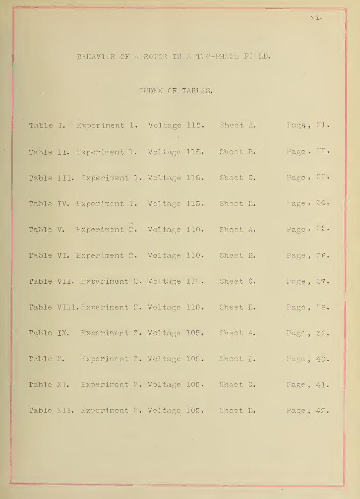
BEHAVIOR OF A ROTOR IN A TWO- PHASE :FIELD.
INDEX OF TABLES.
Table I. Experiment 1. Voltage 115. Sheet Ari. Page,
,
31.
Table II. Experiment. 1
.
Voltage 115. Sheet B. Page »O
Table III. Experiment 1. Voltage 1] 5. Sheet C. Pacre 9
•7 <7.
i . <..«
Table IV. Experiment 1. Voltage 115. Sheet D. Pace >o 34.
Table V. Experiment 2. Voltage 110. Sheet A. Page >
Table VI. Experiment 2. Voltage 110. Sheet B. Pace . 3fl.
Table VII. Experiment C. Vol tage 110. Sheet C. Pace , 37.
Table VIII. Experiment 2. Voltage 110. Sheet B. Pace . 38.
Table IX. Experiment 3. Voltage 105. Sheet A. Pace . 39.
Table X. Experiment 3. Vol tage 105. Sheet B. Pace . 40.
Table XI. Experiment 3. Voltage 105. Sheet C. Page , 41.
Table. XII. Experiment 3. Voltage 105. Sheet D. Page , 42.

XI 1.
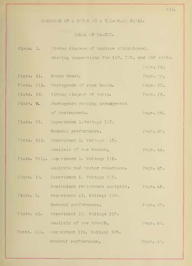
BEHAVIOR CF A ROTOR IK A TWO-PHASE FIELL.
INDEX OF PLATES.
Plate. I.
Plate. II.
Plate. III.
Plate. IV.
Plate. V. .
Plate. VI.
Plate. VII.
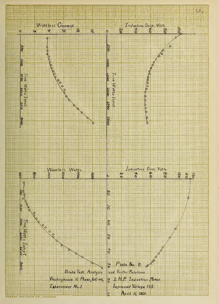
Plate. VIII.
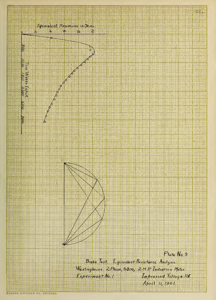
Plate. IX.
Plate. X.
Plate. XI.
Plate. XII.
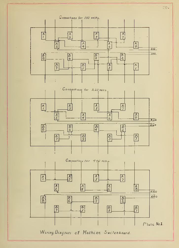
Wiring diagram of machine switchboard,
showing connections for 110, 220, and 440 volts.
Page, 20.
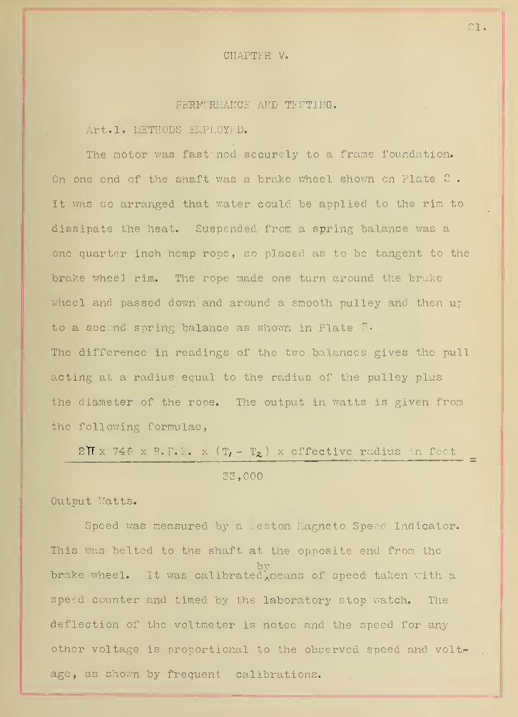
Brake wheel. Page, 22.
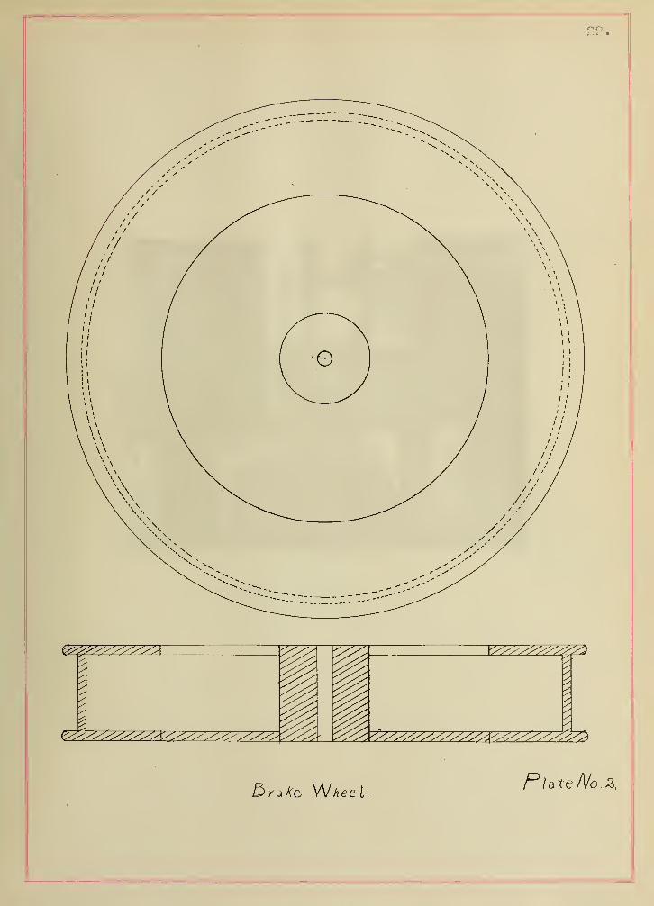
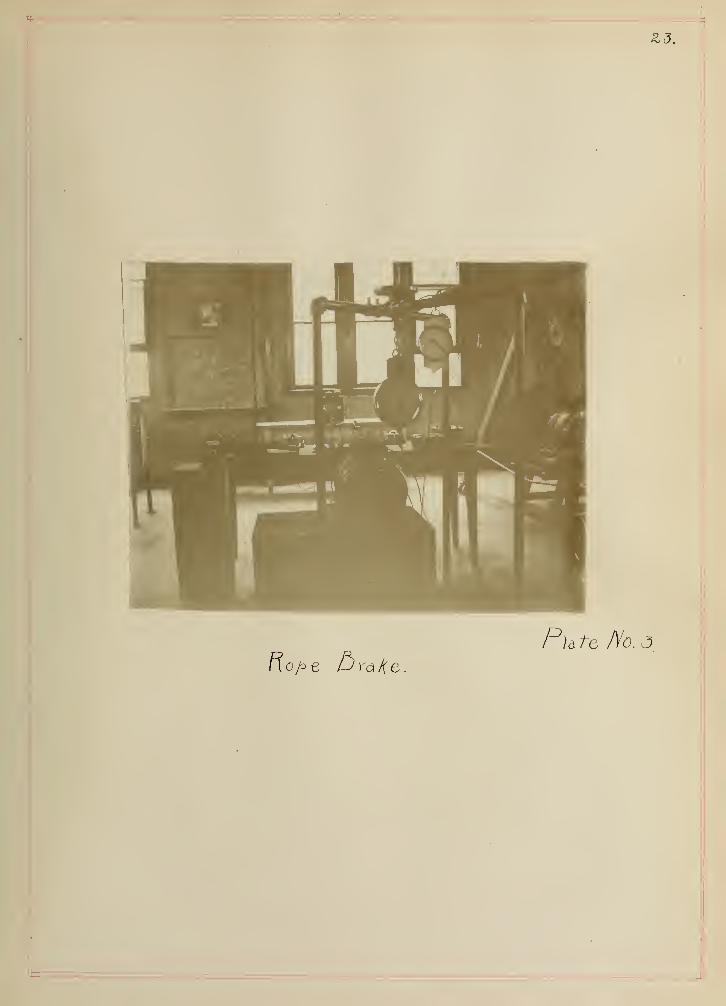
Photograph of rope brake. Page, 23.
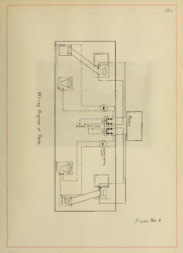
Wiring diagram of table. Page, 25.
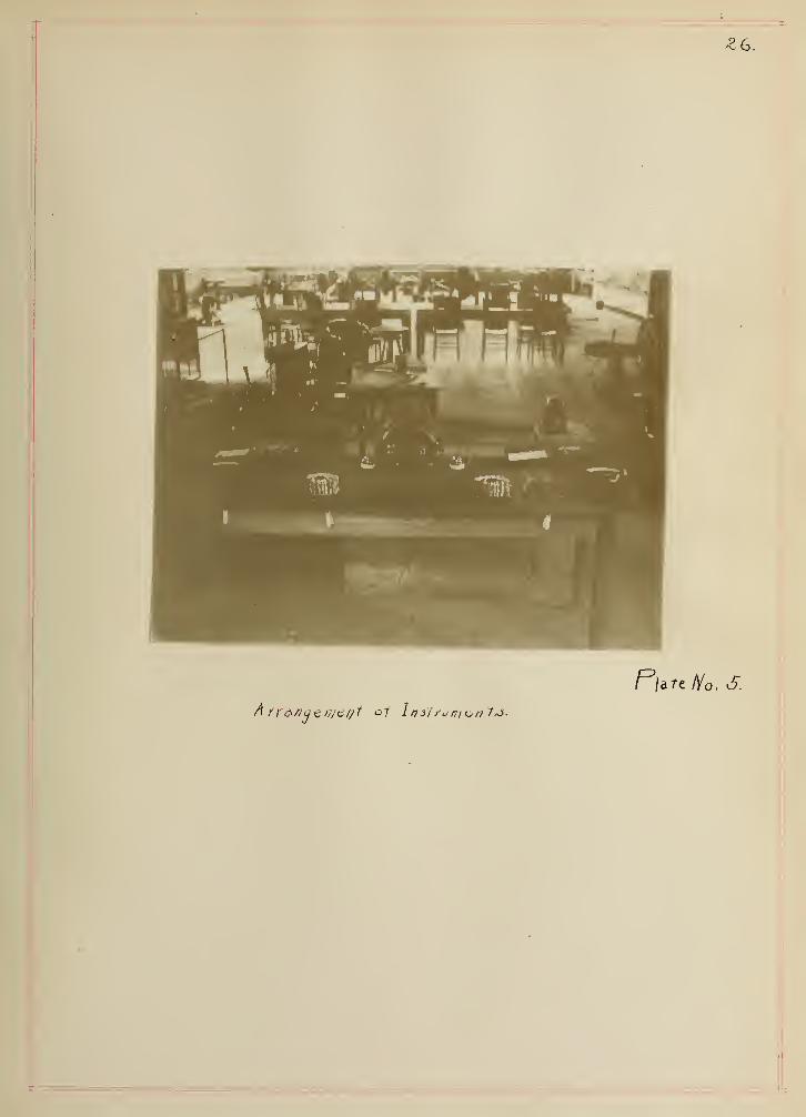
Photograph showing arrangement
of instruments. Page, 26.
Experiment I. Voltage 115.
General performance, Page, 43.
Experiment I. Voltage '15.
Analysis of one branch, Page, 44.
Experiment I. Voltage 115.
Analysis and vector relations., Page, 45.
Experiment I. Voltage 115.
Equivalent resistance ., analysis , Page, 46.
Experiment II. Voltage 110.
General performance, Page, 4?.
Experiment II. Voltage 110.
Analysis of one branch, Page, 48.
Experiment III. Voltage 105.
General performance, Page, 49.

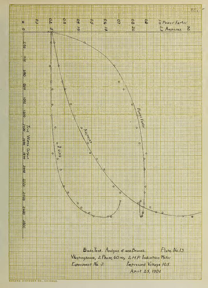
Plate. XIII. Experiment III. Voltage 105.
Analysis of one "branch, Page

y.iv.
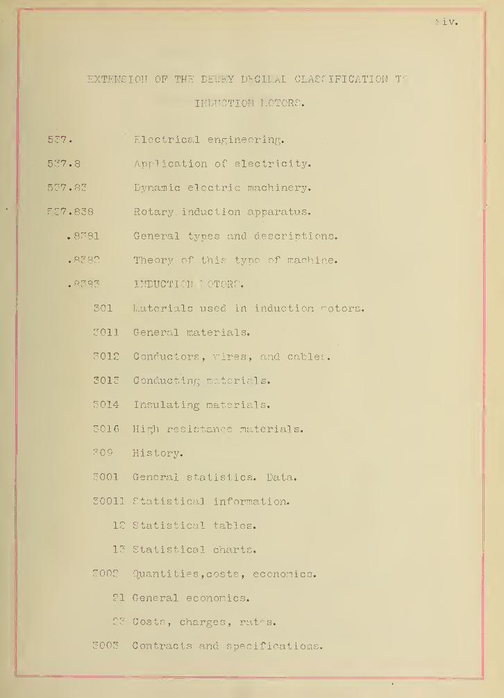
EXTENSION OP THE DEWEY DECIMAL CLASSIFICATION TO
INDUCTION MOTORS.
537. Electrical engineering.
537.8 Application of electricity.
537.83 Dynamic electric machinery.
537.838 Rotary, induction apparatus.
.8381 General types and descriptions.
.8382 Theory of this type of machine.
.8383 INDUCTION MOTORS.
301 Materials used in induction rotors
3011 General materials.
3012 Conductors, vires, and cables.
3013 Conducting materials.
3014 Insulating materials.
3016 High resistance materials.
309 History.
3001 General statistics. Data.
30011 Statistical information.
12 Statistical tables.
13 Statistical charts.
3002 Quantities , costs , economics.
21 General economics.
23 Costs, charges, rates.
3003 Contracts and specifications.

XV.
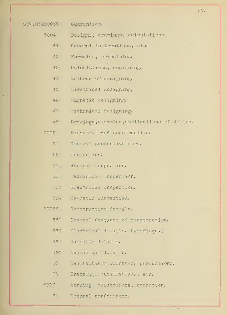
537.83830037 Guarantees.
3004 Designs, drawings, calculations.
41 General instructions, etc.
42 Formulae, principles.
43 Calculations, designing.
44 Methods of designing.
45 Electrical designing.o o
46 Magnetic designing.
47 Mechanical designing.
49 Drawings , examples applications of design.
3005 Executive and constructive.
51 • General productive work.
55 Inspection.
551 General inspection.
552 Mechanical inspection.
553 Electrical inspection.
554 Magnetic inspection.
30056 Constructive details.
561 General features of construction.
562 Electrical details. (Windings.)
563 Magnetic details.
564 Mechanical details.
57 Manufacturing , workshop productions.
58 Erect ing , ins tal lat i ons , etc.
3006 Working, maintenance, operation.
61 General performance.

xvi.
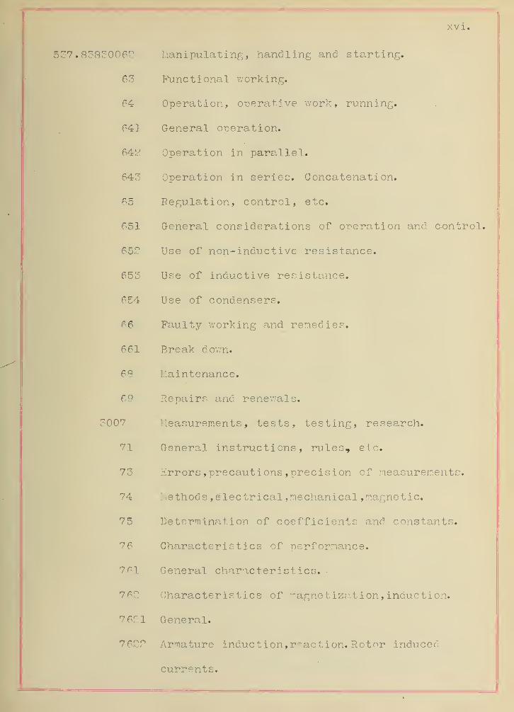
537.83830062 Manipulating, handling and starting.
63 Functional working.
64 Operation, operative work, running.
641 General operation.
648 Operation in parallel.
643 Operation in series. Concatenation.
65 Regulation, control, etc.
651 General considerations of operation and control.
65? Use of non-inductive resistance.
653 Use of inductive resistance.
654 Use of condensers.
66 Faulty working and remedies.
661 Break down.
68 Maintenance.
69 Repairs and renewals.
3007 Measurements, tests, testing, research.
71 General instructions, rules, etc.
73 Errors , precauti ons , precision of measurements.
74 ! lethods , electrical , mechanical , magnetic.
75 Determination of coefficients and constants.
76 Characteristics of performance.
7tl General characteristics.
762 Characteristics of magnetization, indue tion.
7 621 General.
7 622 Armature induction, reaction. Rotor induced
currents.
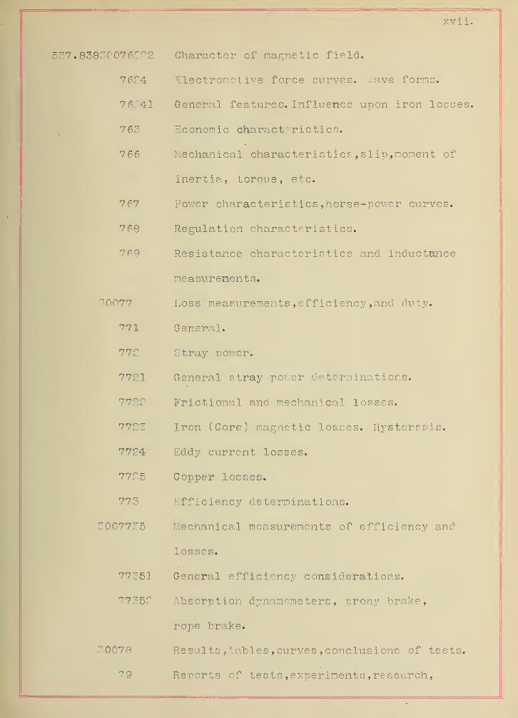
xvii.
537.8383007 6222 Character of magnetic field.
7 624 Electromotive force curves. ..ave forms.
7 6241 General features. Influence upon iron losses.
763 Economic characteristics.
766 Mechanical characteristics , slip, moment of
inertia, torque, etc.
767 Power characteristics ,horse-power curves.
7 68 Regulation characteristics.
7 69 Resistance characteristics and inductance
measurements.
30077 Loss measurements , efficiency , and duty.
771 General.
772 Stray power.
7721 General stray power determinations.
Frictional and mechanical losses.
7723 Iron (Core) magnetic losses. Hysteresis.
7724 Eddy current losses.
7725 Copper losses.
773 Efficiency determinations.
3007735 Mechanical measurements of efficiency and
losses.
77351 General efficiency considerations.
77352 Absorption dynamometers, pronv brake,
rope brake.
30078 Results , tables , curves , conclusions of tests.
79 Reports of tests , experiments , research,
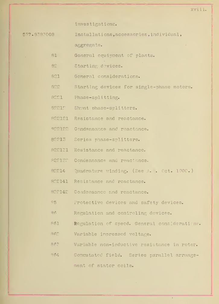
XVI 1 1.
investigations.
537 . 8383008 Installations , accessories , ind ividuaJ
,
aggregate.
81 General equipment of plants.
82 Starting devices.
821 General considerations.
822 Starting devices for single-phase motors.
8221 Phase-splitting.
82212 Shunt phase-splitters.
822121 Resistance and reactance.
822122 Condensance and reactance.
82213 Series phase-splitters.
822131 Resistance and reactance. •
822132 Condensance and reactance.
82214 quadrature winding. (See A. E. Oct. 1900.)
822141 Resistance and reactance.
822142 Condensance and reactance.
85 Protective devices and safety devices.
86 Regulation and controling devices.
861 Regulation of speed. General considerations.
862 Variable impressed voltage.
863 Variable non-inductive resistance in rotor.
864 Commutatec field. Series parallel arrange-
ment of stator coils.

XIX.
537.83830087 Measuring instruments,
88 Listridut ing arrangements , switchboards , etc.
89 Miscellaneous.
30007? National electrical code. Installation of
induction motors.
.83831 Single-phase induction motors.
32 Tv/o-phase induction motors.
33 Three-phase induction motors.

XX
BEHAVIOR OF A. ROTOR IN A TWO-PHASE FIELD.
BIBLIOGRAPHY.
POLYPHASE ELECTRICAL CURRENTS AND ALTERNATING CURRENT
MOTORS, Ey SILVANUS P. THOMPSON, London, 1900.
ALTERNATING CURRENTS AMD ALTERNATING-CURRENT MACHINERY,
By D. C. and J. P. JACKSON, New York, 1896.
POWER DISTRIBUTION FOR ELECTRIC RAILROADS, By Louis BELL.
Third Edition. New York, 1900.
ALTERNATING CURRENT PHENOMINA,
By C. P. STEINMETZ. Third Edition, New York, 1900.
STANDARD POLYPHASE APPARATUS AND SYSTEMS
,
By M. A. OUDIN, New York, 1899.

1.
CHAPTER I.
DEVELOPMENT OF THE TWO-PHASE INDUCTION MOTOR.
Aft. 1. PRODUCTION OF A TWO-PHASE ROTATING MAGNETIC 'FIELD.-
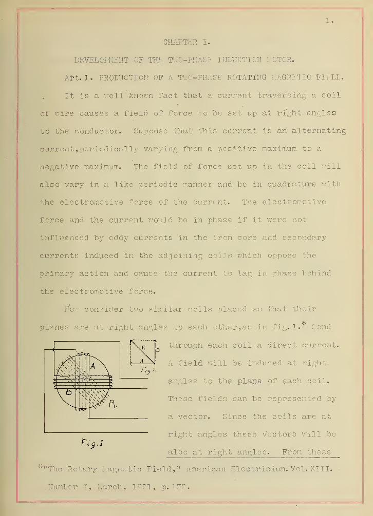
It is a well known fact that a current traversing a coil
of wire causes a field of force to be set up at right angles
to the conductor. Suppose that this current is an alternating
current ,periodically varying from a positive maximum to a
negative maximum. The field of force set up in the coil Will
also vary in a like periodic manner and be in quadrature with
the electromotive force of the current. The electromotive
force and the current would be in phase if it were not
influenced by eddy currents' in the iron core and secondary
currents induced in the adjoining coils which oppose the
primary action and cause the current to lag in phase behind
the electromotive force.
Nov/ consider two similar coils placed so that their
planes are at right angles to each other, as in fig. 1." Send
through each coil a direct current.
A field will be induced at right
angles to the plane of each coil.
These fields can be represented by
a vector. Since the coils are at
right angles these vectors will be
also at right angles. From these
'"'"The Rotary Magnetic Field," American electrician. Vol. XIII.
Number 3, March, 1901, p. 132.

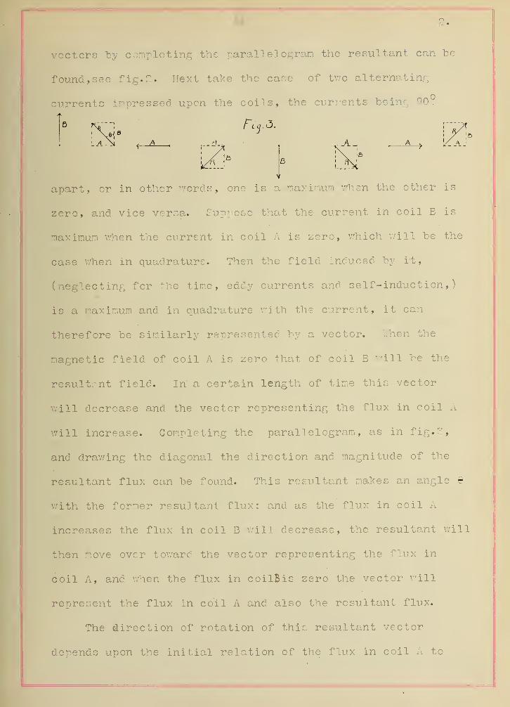
vectors "by completing the parallelogram the resultant can be
found, see fig. 2. Next take the case of two alternating
currents impressed upon the coils, the currents being 90°
apart, or in other words, one is a maximum when the other is
zero, and vice versa. Suppose that the current in coil E is
maximum when the current in coil A is zero, which will be the
case when in quadrature. Then the field induced by rt,
is a maximum and in quadrature with the current, it can
therefore be similarly represented by a vector. "..hen the
magnetic field of coil A is zero that of coil E will be the
resultant field. In' a certain length of time this vector
will decrease and the vector representing the flux in coil A
will increase. Completing the parallelogram, as in fig.?,
and drawing the diagonal the direction and magnitude of the
resultant flux can be found. This resultant makes an angle 9
with the former resultant flux; and as the flux in coil A
increases the flux in coil B will decrease, the resultant will
then move over toward the vector representing the flux in
coil A, and when the flux in coilBis zero the vector will
represent the flux in coil A and also the resultant flux.
The direction of rotation of this resultant vector
depends upon the initial relation of the flux in coil A to
B
(neglecting f or the time, eddy currents and self-induction,)

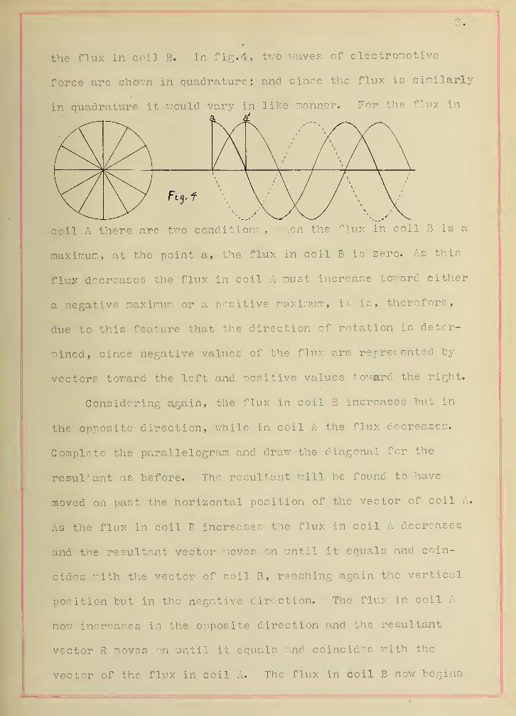
the flux in coil B. In fig. 4, two waves of electromotive
force are shown in quadrature; and since the flux is similarly
in quadrature it would vary in like manner. For the flux in
Fi 3 . f \* x y x / \ * x\^^^yS S X^
coil A there are two conditions , when the flux in coil B is a
maximum, at the point a, the flux in coil B is zero. As this
flux decreases the flux in coil A must increase toward either
a negative maximum or a positive maximum, it is, therefore,
due to this feature that the direction of rotation is deter-
mined, since negative values of the flux are represented by
vectors toward the left and positive values toward the right.
Considering again, the flux in coil B increases hut in
the opposite direction, while in coil A the flux decreases.
Complete the parallelogram and draw the diagonal for the
resultant as before. The resultant will be found to have
moved on past the horizontal position of the vector of coil A.
As the flux in coil B increases the flux in coil A decreases
and the resultant vector moves on until it equals and coin-
cides with the vector of coil B, reaching again the vertical
position but in the negative direction. The flux in coil A
now increases in the opposite direction and the resultant
vector R moves on until it equals and coincides with the
vector of the flux in coil A. The flux in coil B now begins

4.
to increase in the first direction and the flux in coil A
decreases. When the flux in coil A reaches zero the flux in
coil B is maximum and the resultant R has reached the point
of starting. Hence for each cycle of the two fluxes in
quadrature there is one revolution of the flux vector R. If
the current varies according to a sine wave the relation
between the two instantaneous values of the corresponding
flux is such as to always give the same magnitude to the
resultant vector representing the resultant flux.
Art. 2. INTERATION OF A MAGNETIC FIELD UPON ITS INDUCED
CURRENT IN THE CONDUCTOR.
About 1824, Gambey discovered that a magnetic needle
when set in motion, came to rest sooner if the bottom of the
box was made of copper or some good conductor than if it were
made of wood or some poor conductor. Arago demonstrated
before the Academie de Science , in 1824, by several experi-
ments, the' same phenomenon. Re suspended inside copper and
inside wood rings a magnetic needle:' this was pushed aside
from its stationary nosition to an angle of 45° and then
allowed to vibrate and the number of oscillations counted
until the needle came to rest. He found that in the wood
ring there were 144 oscillations, in the thin -copper ring
there were 66, in the heavy copper ring there were only 33.
This showed the damping action caused by the copper ring. He
-"Polyphase Klectric Currents and Alternating Current Machinery"By S. P. Thompson.

decided that there was a force present which existed only
when there was motion and he called this "Magnetism of
Rotation."
In 1825, Babbage and Herschel, showed that if a magnet
placed under a copper disk which is pivoted and able to move
freely, upon being "revolved caused, the copper disk to revolve
also and with a speed somewhat proportional to the speed of
the magnetf They also noticed that if several radial slits
were cut .in the disk the tendency to rotate was grea.tly
decreased.
It was not until 1831, that a theory was founded which
satisfactorly exlained these phenomina. At this time
Faraday showed that when a disk was revolved in a magnetic
field there were currents set up in the disk and that these
currents, called eddy currents, set up a field of force which
opposed, the field of the magnet and hence caused the disk to
tend to come to rest, according to Lentz law.*" He also
showed, that if a copper disk was placed edgewise between the
poles of a strong magnet, and a copper brush was placed on
the edge and one on the shaft, a current would flow through
the wire connecting the brushes, when the dick is revolved.
Therefore, a conductor moving so as to cut the lines of force
of any field will have induced in it an P. I.'.. F.- which will
cause a current to flow, which current in turn has a field of
Thompson Ibid.
Electricity and Magnetism. By S.P.Thompson. Page
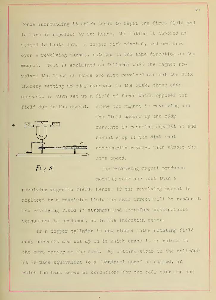
force surrounding it which tends to repel the first field and
in turn is repelled by it; hence, the notion is opposed as
stated in Lentz law. A copper disk pivoted, and centered
oyer a revolving magnet, rotates in the sane direction as. the
magnet. This is explained as follows; when the nagnet re-
volves the lines of force are also revolved and cut the disk
thereby setting up eddy currents in the disk, these eddy
currents in turn set up a field of force which opposes the
field due to the magnet. Since the magnet is revolving and
the field caused by the eddy
currents is reacting against it and
cannot stop it the disk must
necessarily revolve with almost the
sane speed.
The revolving magnet produces
nothing nore nor less than a
revolving magnetic field. Hence, if the revolving magnet is
replaced by a revolving field the same effect will be produced.
The revolving field is stronger and therefore considerable
torque can be produced, as in the induction motor.
If a copper cylinder is now placed inthe rotating field
eddy currents are set up in it which cause it to rotate in
the came manner as the disk. By cutting slots in the cylinder
it is made equivalent to a "squirrel ca.ge" so called, in
which the bars serve as conductors for the eddy currents and
\

7.
and the field set up "by them is stronger and therefore the
torque is greater.
Art.?. EARLY TYPES OF INDUCTION MOTORS.
The first induction motor was made by ..alter Baily, in
1879. There were four electromagnets set horizontally and
close together. Over these and close to them was pivoted a
copper disk. By means of a commutator, which was turned by
hand, a current was sent from the batteries and alternately
reversed in the coils of the magnets, which were connected so
that the diagonal coils were in series with each other. By
this means the lines of force were cut by the disk and eddy
currents were induced in it, hence it rotated. If the
direction of the current in one coil is reversed the
direction of rotation is reversed and if the relative time of
reversals of the current in the two circuits is changed the
direction of rotation is also changed.
In 1885, Professor Ferraris made the first motor which
had a rotating field due to two alternating currents which
differed in phase by 00°. He used two pairs of electro-
magnets connected in series around which was a yoke made of
iron wire. The difference of phase was made by placing in
one circuit a large non-inductive resistance, a, in fig. 6,
and in the other circuit a large inductive resistance ,b , in
fig. 6, and connecting both circuits to a single phase
supply. A closed copper cylinder pivoted between the magnets

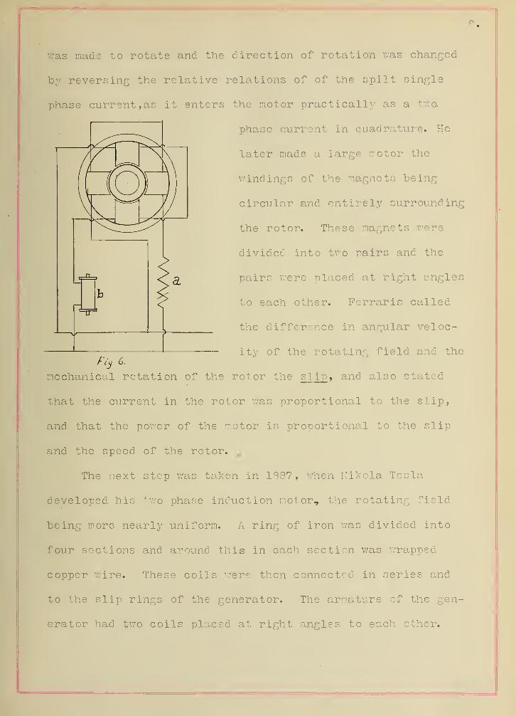
8.
was made to rotate and the direction of rotation was changed
by reversing the relative relations of of the spilt single
phase current, as it enters the motor practically as a two.
phase current in quadrature. He
later made a large motor the
windings of the magnets being
circular and entirely surrounding
the rotor. These magnets were
divided into two pairs and the
pairs were placed at right angles
to each other. Ferraris called
the difference in angular veloc-
ity of the rotating field and the
mechanical rotation of the rotor the slip , and also stated
that the current in the rotor was proportional to the slip,
and that the power of the motor is proportional to the slip
and the speed of the rotor. ,
The next step was taken in 1887, when Nikola Tesla
developed his two phase induction motor, the rotating field
being more nearly uniform. A ring of iron was divided into
four sections and around this in each section was wrapped
copper wire. These coils were then connected in series and
to the slip rings of the generator. The armature of the gen-
erator had two coils placed at right angles to each ether.

9.
Therefore, the E. M. P. of the two coils of the generator would
"be in quadrature. When the generator was delivering a two-
phase current a rotating field was consequently set up in .the
field of the ring forming the stator, and the iron disk
forming the rotor was caused to rotate by it.
CHAPTER II.
THEORY AND PRINCIPLES.
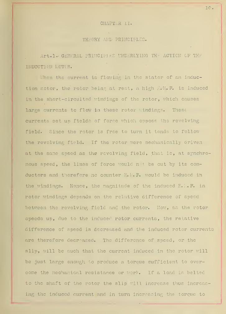
Art . 1 GENERAL • PRINCIPLES UNDERLYING THE ACTION OF THE
INDUCTION MOTOR.
Wheal the current is flowing in the s tat or of an induc-
tion motor, the rotor being at rest, a high E. M. F. is induced
in the short-circuited windings of the rotor, which causes
large currents to flow in these rotor windings. These
currents set up fields of force which oppose the revolving
field. Since the rotor is free to turn it tends to follow
the revolving field. If the rotor were mechanically driven
at the same speed as the revolving field, that is, at synchro-
nous speed, the lines of force would n't be cut by its con-
ductors and therefore no counter E. M. F. would be induced in
the windings. Hence, the magnitude of the induced E. I... F. in
rotor windings depends on the relative difference of speed
between the revolving field and the rotor. Now, as the rotor
speeds up, due to the inducer1 rotor currents, the relative
difference of speed is decreased and the induced rotor current
are therefore decreased. The difference of speed, or the
slip, will be such that the current induced in the rotor will
be just large enough to produce a torque sufficient to over-
come the mechanical resistance or work. If a load is belted
to the shaft of the rotor the slip will increase thus increas-
ing the induced current and in turn increasing the torque to

li-
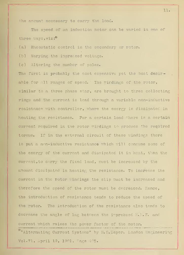
the amount necessary to carry the load.
The speed of an induction motor can he varied in one of
three ways,viz S*
(a) Rheostatic control in the secondary or rotor,
(h) Varying the impressed voltage,
(c) Altering the number of poles.
The first is probably the most expensive yet the most desir-
able for all ranges of speed. ' The windings of the rotor,
similar to a three phase star, are brought to three collecting
rings and the current is lead through a variable non-inductive
resistance with controller, where the energy is dissipated in
heating the resistance. For a certain load there is a certain
current required in the rotor windings to produce the required
torque. If in the external circuit of these windings there
is put a non-inductive resistance which will consume some of
the energy of the current and dissipated it in heat, then the
current, to carry the fixed load, must be increased by the
amount dissipated in heating the resistance. To increase the
current in the rotor windings the slip must be increased and
therefore the speed of the rotor must be decreased. Hence,
the introduction of resistance tends to reduce the speed of
the rotor. The introduction of the resistance also tends to
decrease the angle of lag between the impressed E. M. F. and
current which raises the power factor of the motor.
"Alternating Current Systems" by H.S.Meyer. London Engineering
Vol.71, April 19, 1901, Page 195.

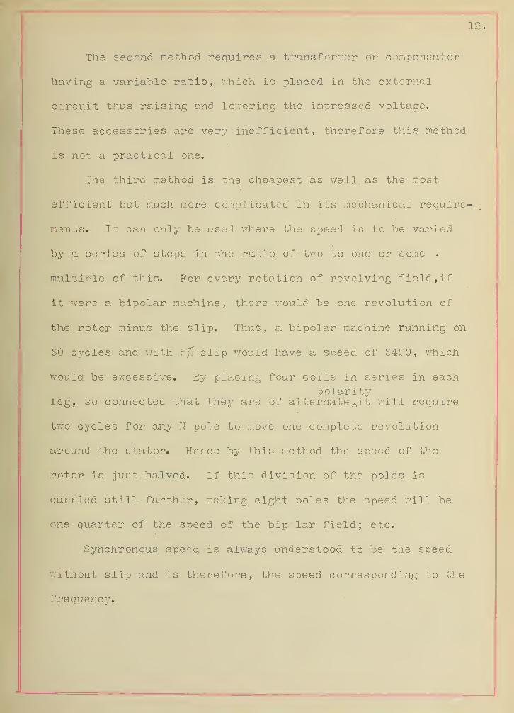
The second method requires a transformer or compensator
having a variable ratio, Which is placed in the external
circuit thus raising and lowering the impressed voltage.
These accessories are very inefficient, therefore this. method
is not a practical one.
The third method is the cheapest as well, as the most
efficient but much more complicated in its mechanical require-
ments. It can only be used where the speed is to be varied
by a series of steps in the ratio of two to one or some .
multiple of this. For every rotation of revolving field, if
it were a bipolar machine, there would be one revolution of
the rotor minus the slip. Thus, a bipolar machine running on
60 cycles and with 5% slip would have a s.peed of 34^0, which
would be excessive. By placing four coils in series in eachpol arity
leg, so connected that they are of alternate Ait will require
two cycles for any N pole to move one complete revolution
around the stator. Hence by this method the speed of the
rotor is just halved. If this division of the poles is
carried still farther, making eight poles the speed will be
one quarter of the speed of the bipolar field; etc.
Synchronous spend is always understood to be the speed
without slip and is therefore, the speed corresponding to the
frequency.

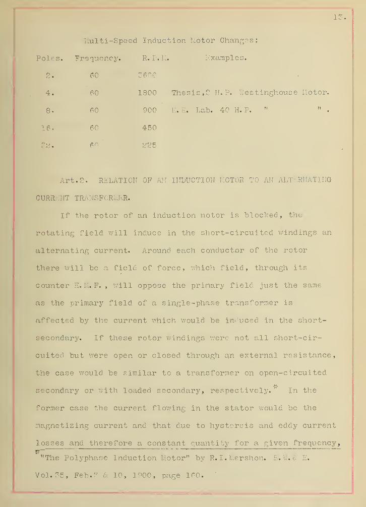
Multi-Speed Induction Motor Changes:
Poles. Frequency. R. P. M. Examples.
2. 60 3600
4. 60 1800 Thesis, 2 II. P. V.'es t inghouse Motor.
8 • 60 900 E. E. Lab. 40 H. P. " " .
16. 60 450
*o 60 225
Art. 2. RELATION OF AN INDUCTION MOTOR TO AN ALTERNATING
CURRENT TRANSFORMER.
If the rotor of an induction motor is blocked, the
rotating field will induce in the short-circuited windings an
alternating current. Around each conductor of the rotor
there will be a field of force, which field, through its
counter E.M. F. , will oppose the primary field just the same
as the primary field of a single-phase transformer is
affected by the current which would be induced in the short-
secondary. If these rotor windings were not all short-cir-
cuited but were open or closed through an external resistance,
the case would be similar to a transformer on open-circuited
secondary or with loaded secondary, respectively. " In the
former case the current flowing in the stator would be the
magnetizing current and that due to hystersis and eddy current
losses and therefore a constant quantity for a given frequency,
"The Polypha.se Induction Motor" by R. L.Mershon. E. W. $ E.
Vol. 35, Feb. 3 & 10, 1900, page 160.'

14
and the copper losses would be very small. In the second
case, as the external resistance is increased the current
flowing is increased and therefore the copper losses are in-
creased and the total losses at any load is the sum of the
losses on open circuit and the copper losses due to the
resistance.
When the rotor coils are short circuited a heavy induced
current flows through them and corresponding energy must be
taken from the line by the s tat or in addition to the magne-
tizing current. The slip in the induction motor is analogous
to the drop in voltage in the alternating current transformer.
Art. 3. RELATION OF THE INDUCTION MOTOR TO A DIRECT-
CURRENT LOT OR.
Upon starting a direct-current motor there is a heavy
rush of current in the armature. This is generally dissi-
pated in the usual starting box resistances which are put in
the armature external circuit. There is a similar result in
starting an induction motor, and it is taken care of in a like
manner if there is external resistance in the rotor circuit.
In the armature of the shunt motor there is a counter E. M. F.
generated due to the conductors cutting the lines of force of
the shunt field. The mechanical work of the motor is against
this counter E. I.I. F. In an induction motor there likewise is
a similar action. A counter E. M. F. is generated in the
primary windings due to the induced currents in the revolving

secondary windings. This counter E. M. P* is similar to the
counter E.M. F. of the shunt motor,- so that in both motors
the speed falls off as the load is increased and no other
change of operating conditions is made;1"
Mershon,I*bid.

CHAPTER III.
CLASSIFICATION?
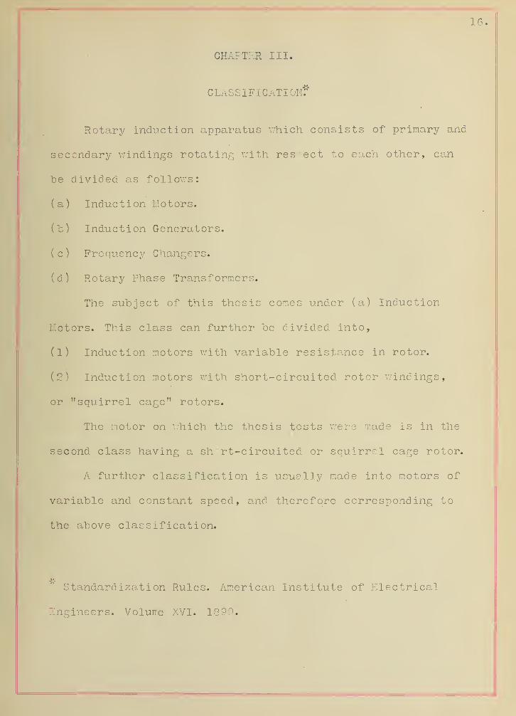
Rotary induction apparatus which consists of primary and
secondary windings rotating with resect to each other, can
"be divided as follows:
(a) Induction I.Iotors.
(b) Induction Generators.
( c ) Frequency Changers.
(d) Rotary Phase Transformers.
The subject of this thesis comes under (a) Induction
Motors. This class can further be divided into,
(1) Induction motors with variable resistance in rotor.
(2) Induction motors with short-circuited rotor windings,
or "squirrel cage" rotors.
The motor on Which the thesis tests were made is in the
second class having a short-circuited or squirrel cage rotor.
A further classification is usually made into motors of
variable and constant speed, and therefore corresponding to
the above classification.
Standardization Rules. American Institute of Electrical
Engineers. Volume XVI. 1899.

17
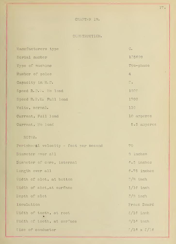
CIIAPTKR IV..
CONSTRUCTION.
Manufacturers type G.
Serial number 135698
Type of machine Two-phase
Number of poles 4
Capacity in H. P. 2.
Speed R. P. M. Ho load 1800
Speed R. P. 1.1. Full load 1700
Volts, normal. 110
Current, Full load 10 amperes
Current, No load 5.5 ampere
ROTOR. .
Peripheral velocity - feet per second 70
Diameter over all 8 inches
piameter of core, internal 6.5 inches
Length over all 6.75 inches
Width of slot, at bottom 3/8 inch
Width of slot, at surface 1/16 inch
Depth of slot 3/8 inch
Insulation Press Board
Width of tooth, at root•
c/16 inch
Width of tooth, at surface 9/16 inch
Size of conductor 5/16 x 5/16
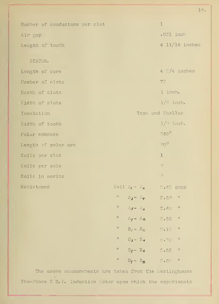
Number of conductors per slot
Air gap
Length of tooth
STATOR.
Length of core
Number of slots
Depth of slots
Width of slots
Insulation
.031 inch
4 11/16 inches
4 3/4 inches
72
1 inch.
1/8 inch.
Tape and Shellac
W 4 r\ + Vi nf + n n + ViII ill Ull Ul uuutii 1/8 i nch.
360°
Length of polar arc 90 u
Coils per slot 1
Coils per pole 9
Coils in series
Resistance Coil A, - Az 2.63 ohms
2.59 it
tf A it
" A7 - A B it
" B,- B^ 2.10 ti
" B„- B« a . 8a it
" Bj-- B 6 2.55 ii
Br- BS 2 . 62 it
The above measurements are taken from the V/estinghouse
Two-Phase 2 H. P. Induction Motor upon .which the experiments

for this thesis were made.
The stator winding is distributed and each pole consists
of nine (?) coils which are connected in series. The ';•
.terminals are brought to a switchboard on top of the machine
where connections can be made for operating at 110, 22.0, or
44-0 volts. A diagram is given on Plate Number 1, showing
these connections.
The bearings are in the casings which close the sides of
the stator. They are self oiling. The rotor is well balanced
and turns very freely in the bearings. It has been found
from three or four experiments, that it requires, on the
average, eleven minutes for the rotor to come to standstill
after the current is shut off, the motor running light at
that instant.

Goqn&cliGfti 'for I/O vajfs.
AZ
bb
A
S
3
A8,
1LQ_
T7Q"
&7
£>
J"
c onneci,o n3 for ZZOvolti.
A3
A5
/A
6
A7
A8
9.
C onne.z1iot) S for *f iO Zoit^,
6
"51
Plate No.2.
Wiring D Ldjra/?] of Machine Switch hoard.

CHAPTER V.
PERFORMANCE AMD TESTING.
Art.l. METHODS EMPLOYED.
The motor was fastened securely to a frame foundation.
On one end of the shaft was a brake wheel shown on Plate 2 .
It was so arranged that water could he applied to the rim to
dissipate the heat. Suspended from a spring balance was a
one quarter inch hemp rope, so placed as to he tangent to the
brake wheel rim. The rope made one turn around the brake
wheel and passed down and around a smooth pulley and then up
to a second spring balance as shown in Plate ?•
The difference in readings of the two balances gives the pull
acting at a radius equal to the radius of the pulley plus
the diameter of the rope. The output in watts is given from
the following formulae,
2tT x 746 x R. P. M. x (T,- Tz ) x effective radius in feet
33,000
Output V/atts.
Speed was measured by a Weston Magneto Speed Indicator.
This was belted to the shaft at the opposite end from the
bybrake wheel. It was calibrated Ameans of speed taken with a
speed counter and timed by the laboratory stop watch. The
deflection of the voltmeter is noted and the speed for any
other voltage is proportional to the observed speed and voltn
age, as shown by frequent calibrations.

Ph te /Vo. J

The electrical input was' measured by a Weston Wattmeter
and Voltmeter and a Thompson Ammeter in each leg. A table was
wired permanently and the instruments set on it as shown in
Plate 4, and in Plate 5.
The current was taken from the University Plant where it
is generated at a voltage of 440. It was transformed down to
110 in two V.estinghouse 0. D. Transformers. There was a
West inghouse potential regulator attached to the transformers
and by this the voltage could be maintained constant.
Art. 2. ERRORS AND PRECAUTIONS.
Having started a test on a certain voltage as the new
load was added it was necessary to allow it to run a minute
or two and so reach a steady value. Errors also might arise
from not having the instruments all read at the same time but
this was overcome as far as possible by having all readings
taken a signal by the person adjusting the load. Before each
reading the voltage was observed and kept constant by the
potential regulator. All instruments were calibrated by
comparison with the West on Laboratory Standards and the read-
ings corrected before calculations were made therefrom. In
all cases single readings alone were taken for each condition
of the experiment.

-pi a r
Plate No. f.
£6.

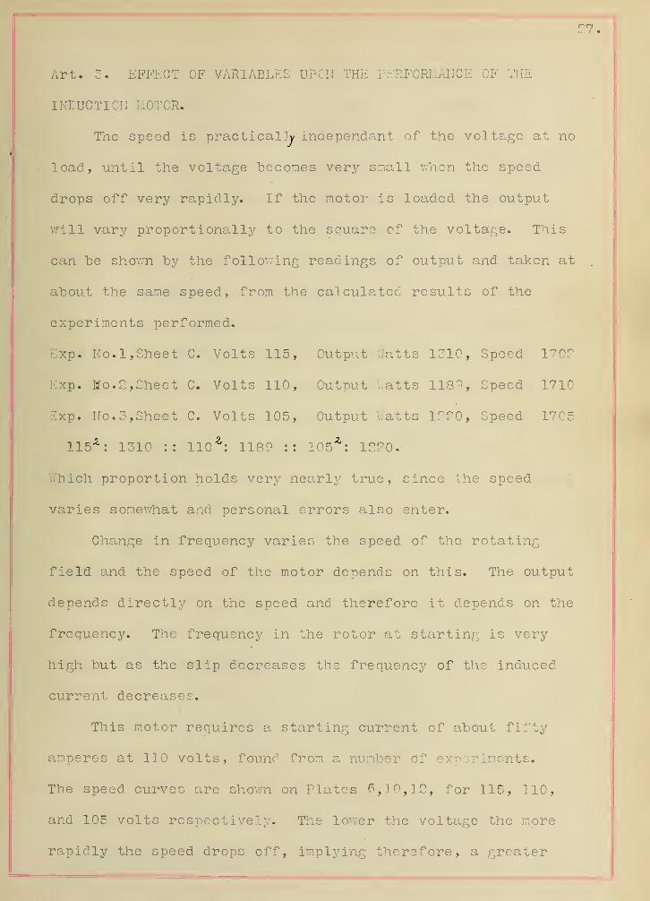
Art. 3. EFFECT OF VARIABLES UPON THE PERFORMANCE OF THE
INDUCTION MOTOR*
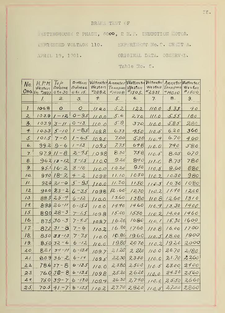
The speed is practically independant of the voltage at no
load, until the voltage becomes very small when the speed
drops off very rapidly. If the motor is loaded the output
will vary proportionally to the square of the voltage. This
can be shown by the following readings of output and! taken at
about the same speed, from the calculated results of the
experiments performed.
Exp. No. 1, Sheet C. Volts 115, Output Watts 1310, Speed 170?
Exp. Mo. 2, Sheet C. Volts 110, Output '..atts 118°, Speed 1710
Exp. No. 3,Sheet C. Volts 105, Output Watts 1220, Speed 1705
115A : 1310 :: 110*: 1189 :: 105*: 1220
V/hich proportion holds very nearly true, since the speed
varies somewhat and personal errors also enter.
Change in frequency varies the speed of the rotating
field and the speed of the motor depends on this. The output
depends directly on the speed and therefore it depends on the
frequency. The frequency in the rotor at starting is very
high but as the slip decreases the frequency of the induced
current decreases.
This motor requires a starting current of about fifty
amperes at 110 volts, found from a number of experiments.
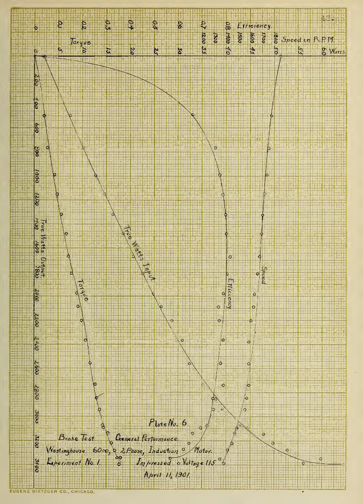
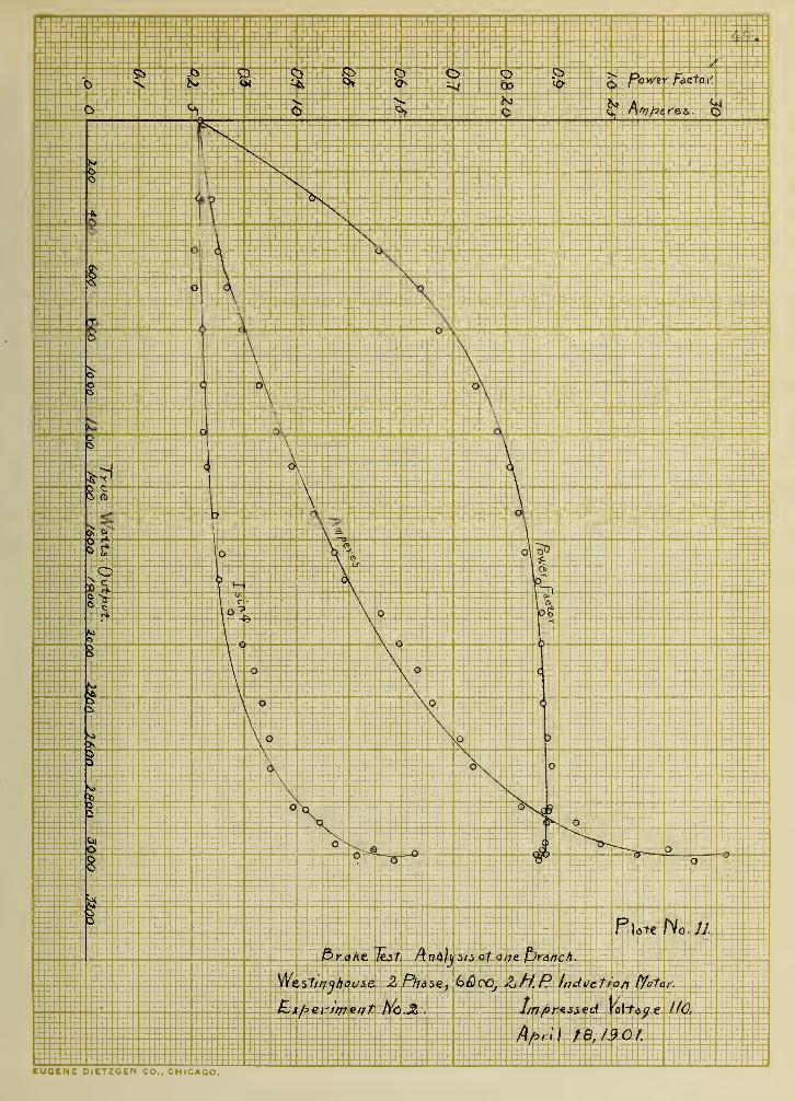
The speed curves are shown on Plates 6,10,12, for 115, 110,
and 105 volts respectively. The lower the voltage the more
rapidly the speed drops off, implying therefore, a greater

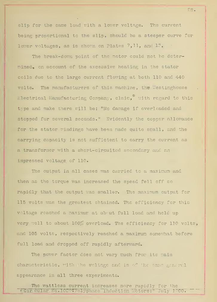
28 •
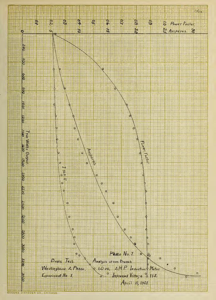
slip for the same load with a lower voltage. The current
being proportional to the slip, should be a steeper curve for
lower voltages, as is shown on Plates 7 ,H, and 1?.
The break-down point of the motor could not be deter-
mined, on account of the excessive heating in the stator
coils due to the large current flowing at both 110 and 440
volts. The manufacturers of this machine, the Wes tinghous
e
Electrical Manufacturing Company, claim," with regard to' this
type and make there will be: "No damage if overloaded and
stopped for several seconds." Evidently the copper allowance
for the stator windings have been made quite small, and the
carrying capacity is not sufficient to carry the current as
a transformer with a short-circuited secondary and an
impressed voltage, of 110.
The output in all cases was carried to a maximum and
then as the torque was increased the speed fell off so
rapidly that the output was smaller. The maximum output for
115 volts was the greatest obtained. The efficiency for this
voltage reached a maximum at about full- load and held up
very well to about 100^ overload. The efficiency for 110 volts,
and 105 volts, respectively reached a maximum somewhat before
full load and dropped off rapidly afterward.
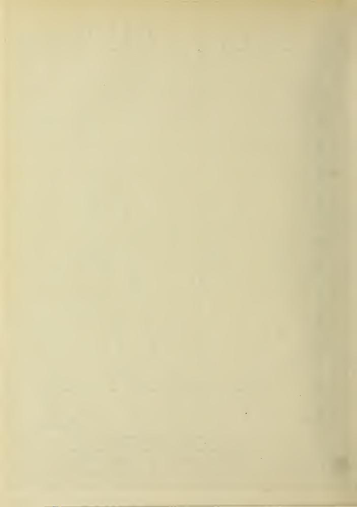
The power factor does not vary much from its main
characteristic, With the voltage and. is of the same general
appearance in all three experiments.
The wattless current increases more rapidly for the~>-Cir, cular No. lU^P'.'Polyphase Induction fAotors:" July lyoo.

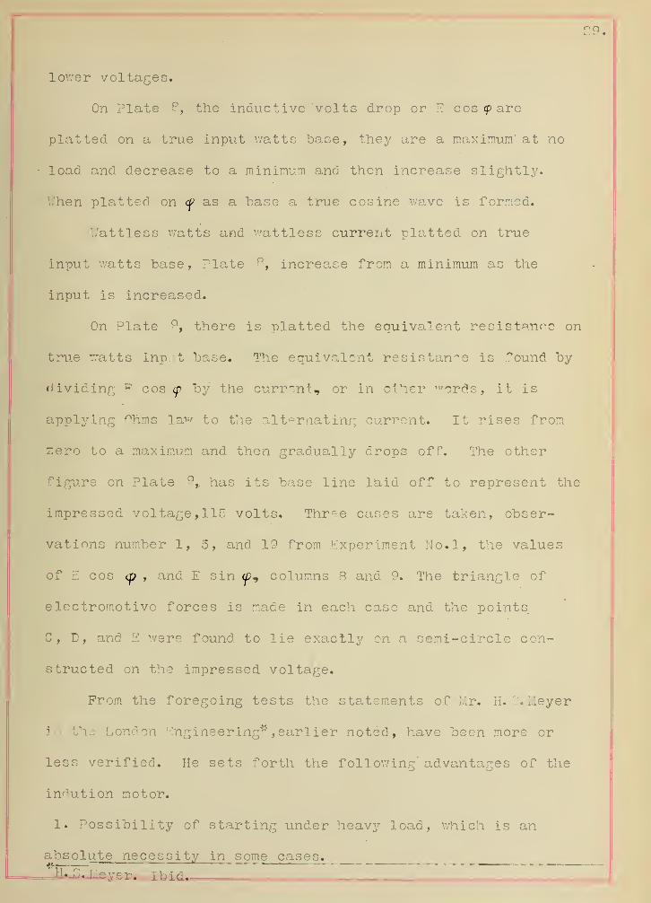
29.
lower voltages.
On Plate 8, the inductive 'volts drop or E cos <p are
platted on a true input watts "base, they are a maximum' at no
load. and. decrease to a minimum and then increase slightly.
When platted on (p as a base a true cosine v/ave is formed.
Wattless watts and wattless current platted, on true
input watts base, Plate 8, increase from a minimum as the
input is increased.
On Plate °, there is platted, the equivalent resistance on
true watts input base. The equivalent resistance is found by
dividing E cos cp by the current, or in other n, ords, it is
applying Ohms law to the alternating current. It rises from
zero to a maximum and then gradually drops off. The other
figure on Plate 9, has its base line 1'aid off to represent the
impressed voltage, llo volts. Thr~e cases are taken, obser-
vations number 1, 5, and 19 from Experiment No.l, the values
of E cos <p , and E sin <p, columns 8 and 9. The triangle of
electromotive forces is made in each case and the points
C, D, and E were found to lie exactly on a semi-circle con-
structed on the impressed voltage.
Prom the foregoing tests the statements of Mr. H. G.'Meyer
in the London Engineering"* , earlier noted, have been more or
less verified. He sets forth the following' advantages of the
indution motor.
1. Possibility of starting under heavy load, which is an
absolute necessity in some cases.Jf- " ... — — ... I I
'
I .. ~ —

2. The primary circuit serves a double purpose, furnishing
both the exciting and load current, thereby doing away with a
direct current exciting source.
3. Great simplicity in mechanical construction, more partic-
ularly in the revolving parts where frequently, by the use of
a "squirrsl-cage" winding all current collecting devices are
avoided.
4. The voltage of the rotor can be made very low, thus simp-
lifying insulation.
5. The motor can be worked at different speeds.

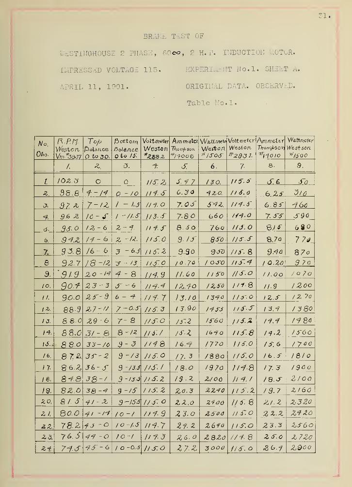
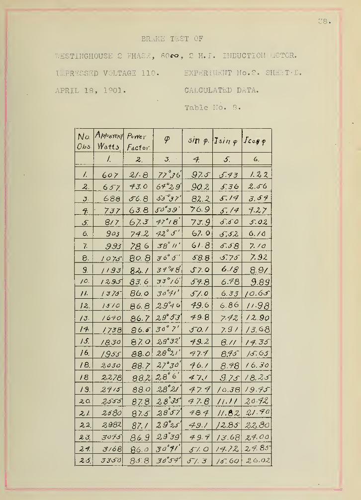
BRAKE TEST OF
Y/ESTINGHOUSE 2 PHASE, 60eo, 2 H. P. INDUCTION LOTOR.
IMPRESSED VOLTAGE 115. EXPERIMENT No.l. SHEET A.
APRIL 11, 1901. ORIGINAL DATA. OBSERVED.
Table No.l.
No,
UPO-
i »• i • i /
WestonTob
to JO.
Balanceo to 15.
Voltmeter
WestonWZB8Z
A YTi tn sXtt.
Thompson.
WaJ.tmefa
Weston\lo\t meter
Weston
^29<5 J-
Thompson^11-0 IO
Wattmeter
Wzstson.v/500
1.o
a. O. 6
.
7-Qo
.
Qy
,
I o Q i/SZ Si 7 130. I'Sf S.G S6
z. 98.
8
T--/7 o-/o 11+ s 6. JO // S o 6 25 3/0
J. 37. & 7-/Z 1 - I.S 1/7- o 7. OS S*Z l/f-S 6.85 *6o
7. 36. Z 16 - S i -/is 1/3. S 7-8 b60. /M-o 7. SS S90
dr. Pis. o 1 Z - 6 z-7. n7.s 8. So 76o IIS. QJ6~
6. 3*z /f -6 z -iz l/S.O 9- IS dso l/S-.S 7 7a
7. $3.8 /6- 6 3 -6.J lld'Z 9.30 <9So l/S. 8 87o
8 92.7 IS-/Z J - J3 l/S-0 ,0.70 / OJD ltd'* 1 Q.%0 3 7o
3. '91.9 Jlo -M -f - 8 tH.9 11-60 1 1 So IISO 1 I.OO / o /o
IO. S -6 l/<?.7 IZ.7Q IZSO //i-S //.$ 1 2oo
II. 9o.o 2S-9 6-7- Hi- 7 13-10 13^0 1 l<T.O 1 z.s / Z 7o
{Z. 88-9 z/-// 7 — o.s 7/S 3 I J.Oo J4SS i/S-S 1 3.7 13 80
13. 8 8-0 7- S //SO IS-2 /f60 l/S.Z 17.7 IfBo
f*. 8 8.0 31- 8 8 -iz /is:/ IS-
1
/6-f llS-8 17.1 Id'60
IS* 8 8.o 33- /o 3-3 1/7 8 M.«f 1770 /ISO IS. 6 /yoa
/6. 87 Z 3S~- 2 9 -73 //SO 17 3 /S8o /ISO / b.S 18/0
1 7. 86.Z 36-jr 9 ~/3.J US- / 18 -O IS70 l/i-8 173 1900
/ 8. 8*3 38-/ 3 -t3 <* l/SZ IS . Z Z/oo IMJ IB.S 2 loo
id. 8Z.o 38 3 ~/S 1 IS. z Z0.3 l/S.Z 13.7 Zl 60
zo, 8 I. S 7I--Z 9 -ISA IIS o ZZ.O IIS. 8 Z/.2 Z3Z0
Z I eo.o to '/ 1/7-9 ZJ.O li S.o z z.z Z7Z0
2.Z. 78.Z fj-o /o-/.S n-1.7 27. Z Z6fo 1 ISO 23.3 Z5~6o
Z3. 76 S 4<? -O to-t 1/7-3 ZG.o Z QZC //* 8 ZS.o Z72o
%f. 7i.S 7-S~6 I o -o.s l/s.o Z7.Z 3 ooo 1/ S. o &6.1 ZQoo

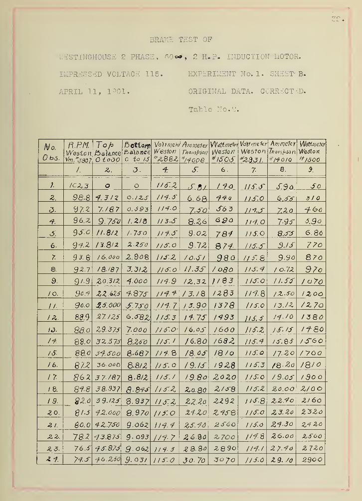
BRAKE TEST OF
V/ESTINGHOUSE 2 PHASE, 60«#, 2 H.P. INDUCTION MOTOR.
IMP&SSEB VOLTAGE 115. EXPERIMENT No. 1. SHEET' B.
APRIL 11, 1901* ORIGINAL DATA. CORRECTED.
Table No. 2.
No.
n
ft P/VWeston
To hbalance
£ oOO
ft fi>tto«»
balanceto 10
WesionA0O0Z
Am mp.leyr 1 1 r/ 1/ f \s ( \_ /
7/70/77/5JO/7
^/fooe w 10 03
Vo)fi7?e1tr
*Zd3 /.
Wattmeter
^1600
/ 2 <*J4.1. u A 8
;. o 1/6~.Z if. 8/ / 90 l/6-.3~ S36 So
z. 98.8 O./ZS 6.68 -flo us.o 6.S3 3/0
a.cJ7-2 7-/67 O. S93 IMO 7.3-0 S63 IM.S 7.ZO
* 36.
z
9- 7Sa I.ZIQ II 3.S S.Z6 ego 7-9S S.90
SS.o it.S/z / ISO l/f-S 9-OZ 781 115.0 8.SS 6.86
6. / 3.8/2 z.zsra //SO S1Z II5.S 3.IS 770
93.Q /6.00a Z.%0% i/sz /O-SI 980 US. 8 9.9o 8 7o
8. /Q.I81 3 3/2 71 so i).3S / 080 ns.i lo.7Z 97oa. 9 / 9 Z0.3/Z ^.00 U1-9 IZ.3Z ;/Q3 1 ISO 1 1. ss / a 7c
/o. ZZ.6ZS 9-87S //?.* Z3./8 /2Q3 1/9-8 /z.so /Zoo
/ /. £5. 000 S 7X0 //i- 7 1 3.90 1378 //so I3./Z /z 70
i z 89.9 27. /ZS &.S8Z US3 !f-7S 1195 IIS. 3 11. /o /380
13. Z9.37S 7-006 //SO' 1 6. cs /660 JlSZ is. IS ii-80
88.o 8.Z6'o t/S. / /6.QO /68Z list IS. 85 /SOO/<5". 89.0 6-687 //?. 8 /8.0-S IQ/o I/So /7.Z0 / 700
/6. 87-^ 36 60S 3-8/
Z
//S. 1'9. IS /9Z8 1 iS.3 /Q.Zo /Qio
1 7- 3 7/87 Q.8/Z i/s. / 19. 80 ZOZO /ISO /9.os /So
1 8. 818 38-937 8-89S iisz Za.so l/SZ Z0.00 Z/o c
19, gzo B.937 IISZ ZZ.Zo ZZ9Z j/s.8 Z2.<?o z/60
2 0. 8 is f2. 000 8.97o //3-.0 li-ZO Z-93S 1 /So Z3.Zo ZJZo
-3 /. &0.0 4ZJ30 9-o6z I /<?.<? ZS.16 2o~60 //So Zi-30 ZC
7&Z 13.87S 9- 093 1/17 Z6Q0 z. 700 //-f-8 Z0.O6 Z.S60
£ 3. 76.S IS 873 9.06Z 1113 ZQ.Qo ZQSO /MJ 2 7.<?o Z7Zo
Hs 9.°y/ 1 1 f.O 30- 7o 30 70 JISO Z9. /c 2900

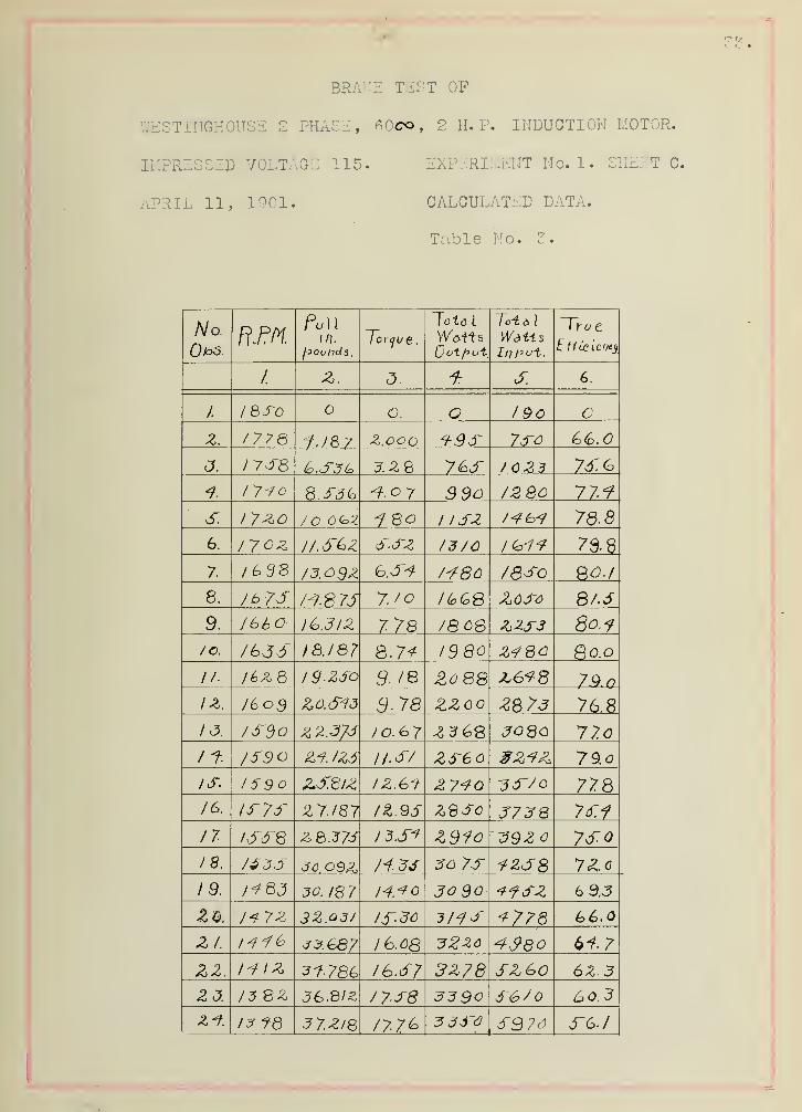
BRAKE TEST OF
WESTINGHOUSE 2 PHASE , KOco , 2 H. P. INDUCTION MDTOR.
IL1PRESSID VOLTAGE 115. EXPERIMENT No. 1. SHEBT C.
APRIL 11, 1901. CALCULATED DATA.
Table No. 5.
K 1
No.Pi,))f U 1 L
in.
Jot&
I
U ol f> ut.
To-i a \
WaUsIII pvt.
~Vy u t
EffLciei/tj
i <<j .
4. <-.
L.
1. I&so O. O 190
z. 1778 jje>7 Z.000 t9S 7SO
J. I7SS (o.S3(o 3. Z 8 7&S 1 023 7S.(o
f. I 7-70 8.S3(a 9 9o 72 80 77.9
6". I 7^0 / O 6<°Z 1 ISZ 78-8
6. 17'oz l/.d'^Z s.sz 1376 7S-d
7 i^ds /3.0>$Z /-780 I8S0 9>0.f
8. M.87J 7. to HoGS Z03-3 8/.S
9. /66C )(o.3IZ 7-78 /8 0S &2S3 80.1
/©. 18.187 8.7* 1380 Z<?30 80.0
// I6&Q 19-ZSo 9- /8 &088 79.0
I609 3.78 ZZoo Z8 7J 76.8
/ i3. /S~9o Z 2.3/S IO.&7 so 80 77.0
/f /S9 /ZS //.«*"/ zsec 79.o
IS, 1590 Z,J~.8lZ iz.61- £740 S6~70 778IS. IS73~ Z7./87 iz.95 zeso J7S8 7d:i
11 IS~S~8 z 8.37S I3.S-? Z31o ?92 7SO18. t$36 J0.O9Z li-ZS 30 7S <fZJ8 72.0
19. I^QJ 30. 18 7 H.^o 30 So tfSZ 6 9.3
ZQ. /«* 7Z 3ZPdl 13-30 -3MS 1-778 66.0
Zf. J3.G87 /6.0S (>i-7
Z2. IflZ 3f. 786 I6.3~7 3Z78 SZ60 6Z 3
Z 3. 13 BZ J6.8/£ /7S8 S3 9c S670 60.3
Zf. 1? fd 37.Z/8 /7-7<° 333~6 S97J 5~G./

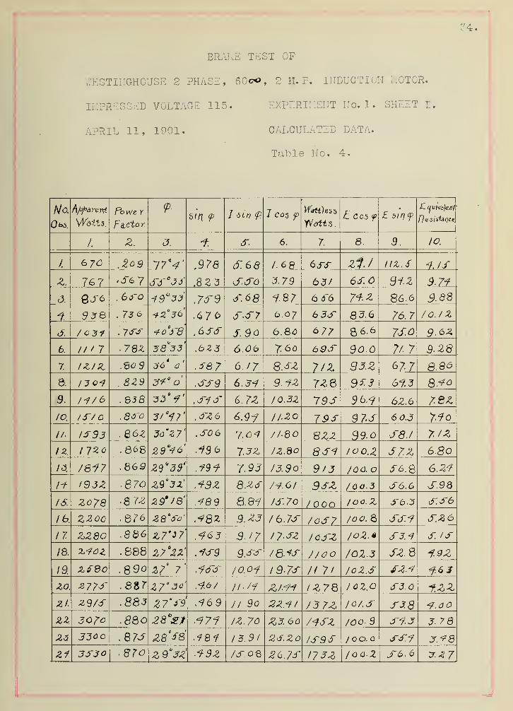
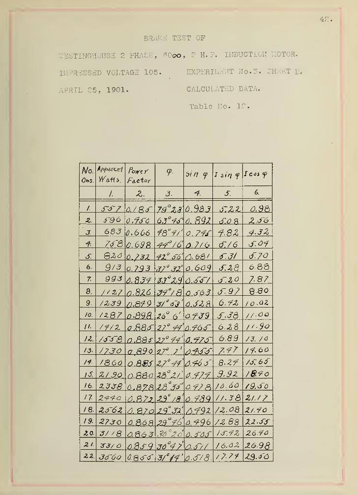
BRAKE TEST OP
Y.'ESTIMGHOUSE 2 PHASE, 60co, 2 H. P. INDUCTION MOTO&;
IMPRESSED VOLTAGE 115. EXPERIMENT No. 1. SHEET L.
APRIL 11, 1901. CALCULATED DATA.
Table No. 4.
No.
Obi.
Apparent
Watts.
PoWe Y
F q r'f.o y
<DTbin <p J <5tV? <P 1 Cog f
Wattles?,
TJ&tt 5 .
L cos y
1 2XL)
.
I/.-4/
< A 7 8 a
/ .978 S.68 1.6 8 635 Zi.7 nz. s 1. If
Z. 7G7 ,56 7 dTf'JJ .8 2 3 d~.<5o 3.79 63/ 6fO 91.Z 9.71
c5. QJO . 660 Jd~
9
^. 68 1.87 6f6 71 z 86.6 9.88
93& . 73 6 .67 6 5-57 6.07 6 35 8 3.6 76.7 /o./z
j: /63f . 755 *o J 8 .655 5. 90 6.86 677 8 6.6 7S.0 9-6Z
6. II / 7 . 782 38 33 .623 6.06 7.60 635 90.
Q
77 7 9- 28
7. IZ/Z 36 a .se 7 0.17 8.5Z 7 IZ 93.Z 677 8.86
8. /304 .8ZS 3*° .559 6.31 9.1Z 7ZQ 963 61.3 8.40
9. . 838 •33 1 .615 6.7Z IQ.3Z 79S 96.<? 6Z.6 78Z
/a 15/
o
.850 3' 17 .5Z6 6.9<? ll-ZO 795 97S 6 0.3 710
//. 1533 . 86Z 3ca
Z7' ,50 6 7.04 //80 8ZZ 39.0 S8J 7. iz
I 7Zo . 8^8 29 46 19 6 7-3Z /Z.80 851 100.Z S7.Z 68013. 7817 .863 Z^
Q3S' .191 7-93 /3.9o 9/3 J6Q. O JT6.8 6.Z1
ii- I93Z &70 Z9°3Z' .19Z 8.Z6 74.6
1
96Z /CO.
3
S6.6 f.98
2o?8 • 8 7Z Z9'/Q' .489 8.81 /6.70 /ooo /oc.Z 56-3 6.66
lb. ZZoo .Q76 Z8°5d' ,1Q% 9.Z3 76.75 /03-7 /oo. 8 ss.i 6~.Z6
17. ZZ80 .866 Z7'37' .^63 S.I7 J7-6Z J63~Z /oZ.* 63.4 5. /5IS. XlOZ .888 Z7°ZZ' .13-9 9.65 78-45 J/oo 702.3 6Z.8 i.9Z
19. Zf8o .890 Z7° 7' .165 10.01 1 9-75 // 7
1
JoZ.S 5Z.4 1.6 S
zo. 27 7
S
.8S>7 Z7" 3d' .1.6/ IZ78 I OZ.O 63.0 -f.zz
zi. Z9/5 .883 Z7°f4 .169 //. 9o 2Z.1I 76 7Z /o/.S 538ZZ 307° .8Q0 .171 IZ. 70 Z3. 60 713~Z /oo. 9 51.3 3 78
za .876 ZQ°68 .481 13.91 25. Zo 1595 1 00. 55.1 3.4833-30 87o Z9°3Z 19Z /SO® 26.7f .17 3Z /oo.Z J-6. 6 J.Z7

BRAKE TEST OP
Y/ESTINGHOUSE 2 PHASE, 60©D, 2 H. P. INDUCTION MOTOR.
IMPRESSED VOLTAGE 110. EXPERIMENT Ho. 2. SHEET A.
APRIL 18, 1901. ORIGINAL DATA. OBSERVED.
Table No. 5.
No. R PMf i , / / ITo k
to jo to /S.
We si.on^2Q8Z
Weston*/3~oS.
VolfmiAtY
We sion
*ZS3I *MD/0
W&tlflKitK
We s ion.
/.oso
,
<J.•ro 6. 7 8
.
Q\J
i /06 8 O // a. 6 o.Z IZ2. //o. S.3S
z. /0J.9 / -/Z -9.S // fi Z70 1//.0 s.ss I80
foj.9 J'// Q -/J. I/O A S'S 3 7£> l//).o T.8S Z80I QS3 S'-'o / -&jf
/O.9. 8 6.33 ffo l/O.S 6.20 366
<5. 1 O/.S 7-0 / ^ 6.S loss 7.0o d~30 ///*>.-? 6.70 4 606. 39-2 / -/3. 103.6 77S 6f-6 //o.o 7.^0 3TS0
7- 979 // -8 /0 9.8 8.S<o 7J~&. 1/6.3" epo8. 96.Z /j^/Z 3-/.S ) 10.0 9.zc ///-/] S.7J 7S09. 9 S.i I6-Z 3 -/o l/G.O 1 o.zo 9so II0.S 9.6c 880to. 9?o /8-Z I0 9.Q 1 I. lo 1 od'o l/o.z / 0.30 9 80// 92.° S'SJ Jto.C //. 3o use //4.S /O.30 10 80
IZ. 900 6 ~3.S /0,9.B IZ -60 /Z70 //o.Z //.¥o /ZOO
io &S-S 6-/Z )7 o.o 1 3.60J 3 SO I/0.8 /Z.60 /3/0
If. 89.9 2 6-// 6-/S.J !/ C.6 /4.<?G 60 //6.<7 /3.JC 7^00)
13 8 9.0 Z& J 7-/.S /o9.8 IS', oc /SSO //o.Z /4.00 /<?60
16- ft7A JO -J 7-i.s 103.7 1 6Z0 16 SO //o. / IS~.3o I60O
n H7.Z 3/ -a 7-6 l/o.Z 1760 //4d /6.60 770O
18. 8J0 733-/3 7-7.S / /n.O ie.Qo /9 60 //o.S /8.00 I900
19. SS.o 3Z ~6 6 -/Z //CO 19.80 ZO 70 s/o.z J9Z0 Zooozo 6 -I3.S
/09-X ZI.ZO Z Z%o //6.0 ZO.70 Z78036-JL 6 - /f /OSS' ZZ.36 Z3SO 1/0.6 %\.?o ZZ60
ZZ. 78-6 37-
8
t> -/J.J" //o. Z3.80 zsoo l/A- S Z3.oo %ioo
23. 76.0 JS-8 6 -/JJ /OS, 8 ZSZo Z 620///). ZS60
Z f TS.o 30-
7
6 -13.0 Z740 I/O. Z d~.S0 Z6602S. 7o.3 11 ~7 b ~/JS / /o.Z Z7TO ZQZo //d. d~ Z7.44 ZQ60

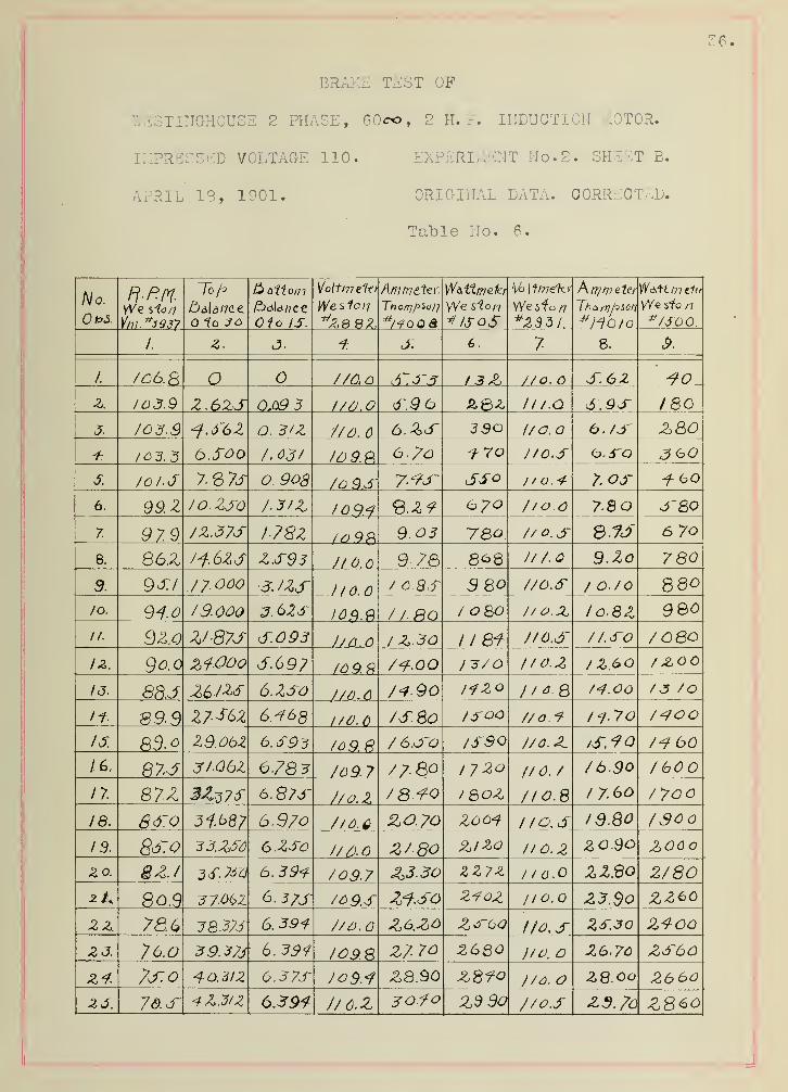
BRAKE TEST OF
iSTIITGHOUSE 2 PHASE, 60co, 2 H. ?. INDUCTION MOTOR.
IMPRESSED VOLTAGE 110. EXPERIMENT No. 2. SHEET E.
APRIL 13, 1901. ORIGINAL DATA. CORRECTED.
Table No. 6.
No.
U Pwi
n-npf.VVe sW/
la h
1c JO
f\ Hi1^ Oil Ot/7
Oio IS.
Volt/77 eit/
^8 8Z
AM hi fi "f-p r/ \/ff //ye ttri.
Tho/?]pS<J/j
*/<?QQ&
Wdii1.tn(>1er
VVe si 0/1
* ISoSWe if0/7
t\ tft hi c fpi
Th a mj^^on
W&1t hit let
*/S00/
<i 77jt L
. 7 0.
/. /C6.fi o 770,0 <7T.3T3 770.0 S.6Z
Z. 103.9 Z.6ZS 0.Q9 3 7/77.0 S.9 6 £Q2 ///.a S.93- /so
3. /03.9 ^.6'6Z O. B/Z 777). 6 6.ZS 390 l/o.o 0./3~ Z804 /033 6SOO /.037 10 9.9, 6./0 ?• 70 7/0.S <o.S~0 JOO3. 10 l-S 7- 8 7s 0. 90s 70 9.S 7.-9S~ iSSO / / 0.4 7. ojr 41 60
6. 99. Z /o.Zso 7-3/2, / 0.9.4 <d.Z<? 6 70 7/oo 78 3'80
7. 979 7Z.37S 1-782 lo 98 9.03 78o 7/ 0.s 8.JJ 6 7o
8. 86Z /1.623 Z.S93 J10.6 9- 78 8^8 7/7. C 9.Zo 780
9. 9SI / 7. 000 3. IZS ) (0.0 7 O SS 3 SO 7/O.S / o./o 88Olo. /9.000 S. 62S JO$.fi 7/.RO I 080 7/o.X, I0.8Z 9®o
II. 9Z.0 Z/-87J dT.093 J/ 0.0 / Z.30 II 81 7/0,6' 71. SO 7 08O
IZ. 9co Zf.Ooo S.697 /09.fi 7^7-.0O 1 -370 //O.Z /Z.bO / JcOO
id. 8RJ Z6-/ZS 6.ZSO 770.Q 7<t9o /4ZO l/*8 74.00 /3 /O
if 899 Z7-S6Z 6.168 1/0.6 7S.SO IS-oo 7/0.4 /4-70 7^700
16. 83.° 29.062 6.S93 76 9.fi 7 6.S~0 73~9Q 7/O.Z (S.?0 7*9 60
/6. 87.3 J/-06Z 6783 709.7 77-80 1720 I/O. / 76.90 7 60O
it 87.Z 3Z?7S 6.873* 7/o.Z 7 8-^0 l 8OZ I/O.8 / 7.6O 7 7oo
18. 6<s~o 31.687 6.970 7/0.6 ZO.70 2004 l/o.s ie.Qo 7S0O
19. ~33.ZS6 6-ZSo 7/AO z/ 80 Z/ZO I/O. 2 zo.90 ZOOoZo. 8 Z.I 6. 394 709.7 z>3.30 ZZ7Z / (0.0 ZZBo 2/802L 803 6.3/S 70 9.S 240Z //o. Z3.$o ZZ60
2 2. 78.6 3Q37S 6.394 7/0.0 Z6.ZO Z<T6d t/0,S ZS.3Q Z400Z J. 76.o 39.37S 6.391 109.8 Z7 70 2680 )/o. Z6.70 ZS60
24. 7J-.0 40. 312 6.37S 7o9.<? £8.90 Z8?o 7/6. 28. 00 2660zs. 76-S 4 Z 6,39* 7/6.Z BO.fo Z3 90 7/0.S Z9.7o Z860

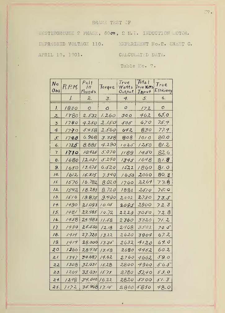
BRAKE TEST OF
NESTING-HOUSE 2 PHASE , 60co, 2 II.?. INDUCTION MOTOR
IMPRESSES) VOLTAGE 110. EXPERIMENT No. 2. SHEET
APRIL 13, 1901. CALCULATED DATA.
Table No. 7.
/V o.
ObS.
Pel)
f~~ouii d S.
l yv e
Uujpo T.
To1* I
True Y&fts1 rut
2, o • /• 6.
1 1830 O 77Z
z. /78o Z.S3Z 7.Z60 JO 6J~.0
3. 77$o 2. /SO sos 6pO 7S.-9
4. 77? Q 2.S60 6<?Z §3Q 77.<7
S. 6.968 3. 338 70/ QO.O
6. 888f <f.Z9o 7Zd~0 Q/-Z
7- t7fo /o.-izs 0.0/0 f'Q9 7<?SO 82.6
8. 7680 S-ZyO 76*78
9. I 66~0 / 3. 6/<f o&ZO )3'Z1 7 860 8/-
10. 7b/Z I6~.3?f 7 6J~4 Z06O 80. ^
II. I6'76 76. 7Q2. 8.0ZO 7760 7 7* $
U. 7S7Z I8.Z83 8-77 ZS/O 7s, O
/ J AT/
6
/3.&7S $.*79o Zoox Z7JO 73.SIf Z/093 /0.0& 2L09S Z90O 7 2>- 3
i j. /<z / XjA. ./aJ / o./z z ZZd jO Q 7 Z. a
7<fSQ Zi-783 I/.S8 Z 360 33Z6 77. Z
n 7<?S0 /z./s Z<?68 JSdZ 70. s/&. /3.1Z Z6ZO 396*7 67Z19. /<?/f 28.ooo J3.36~ Z63Z ^/ZO 6t%a 1366 Z8-77S J3.JQ Z68O <?<7SZ 60.
Z
z/. l~317 2 0.68
;
Ji.ez Z760 466Z d~9.
zz. /30Q JZ.Q3/ 7S.Z% Z800 -7960 S6.S23. IZbf 3303/ /s.ys £780 SZ<7 J-J.
Z + 7Z<7% 3"?, aaa 76. ZZ ZSZo SSOO S7- 3
25. //?2 3S. 968 1 7. 7f ZQOO SQSO 18-0
BRAKE TEST OF
WESTINGHOUSE 2 PHASE, KQco , 2 H. P. INDUCTION MOTOR.
IMPRESSED VOLTAGE 110. EXPERIMENT No. 2. SHEET' £>.
APRIL IS, 1901. CALCULATED DATA.
Table No. 8.
No.1/1/ . * A ,
Po We v? dip
f. 7 sin f fcof f
/. 2. 3. S. 6.
/. 2/>8 77*J 6 97 J~ S.43
Z. 6 J~7 43.0 64°29' 90.Z S~.36 2.f6
J. 688 J-6.8 Sf°j7' 82.2 £~./4 3. ^4
f- /\J7 6d.& 76.9 6~/4 f.Z7
S. 1-7 °/e' 73.9 S.02
6. 74.Z 42° s' Q>7. tf~.S2 6.76
r 78. 6 38 II 61.
8
6-.3~8 7. '0
8. Bo. 8 SS-8 7.31
9. / 133 SZ./ 3 * v e' S70 6./S 8. 9//o. 1 Z9S 83. 6 £-<?& 6.48 3.89
II. tsidr- 86. o J~7.o 6.33
IZ. 86. 8 Z9°4<>' 1-9.6 6.86 //9813. / 610 86.7 29* S3' 49.
8
74
Z
/2.90
14 1738 Q6.47 36° 7' J~0. / 7-9/ J 3.68
/830 Q7.0 Z9"3Z' 49.2 a// /4- ~33~
8S-0 28°Zi' «?74 /3-.6S
/a 88.
7
Z7°30' 46./ 8-48 / 6. 36
18 ZZ7Q 88.Z 28 6 47J 9.7s 78.ZS
7 3. 2,4/S &8.o 28°2/' /o.38 J9-4S
87-8 <?7.8 //,// 20-4ZZ
Z6-Q0 Q 7.S Zd°S7' 4S.4- //.e>z Z/.4Q
A3. Z982 87/ 2 9%y 4-9. / JZ.8S ZZ.dO
&3. 86.3 29°39' 4 3-4 13.68 24. 00
3.4. 3/68 Q6.o joy/ f/. o /4-7Z Z4-86-
26. 333~6 8^8 JT/. 3 /6~. OO ZG.Q2
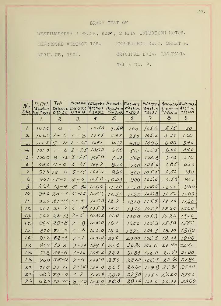
BRAKE TEST OF
V/ESTINGHOUSE g PHASE, 60c* , 2 H. P. INDUCTION MOTOR.
IMPRESSED VOLTAGE 105. EXPERIMENT No. 3. SHEET A.
APRIL 25, 1901. ORIGINAL DATA. OBSERVED.
Table No. 9.
No.
Up 6.
ft. ''
We 3"* 0/7
VW. J.9J 7
iu i
to JO
P>o'itotn
Q to IS.
We 5to a?
l\ ni nip4p v
v7*oo&
W&it i7ieftr
yi7e s ft>/7.
*/5Q 5
rt) XT frlzTtY
^£93 1
Vi H./7H.KT
We ifo/y.
6~Qo
/
/. Z. O.4-T fr 6. 7 8 9
1. / J. O 1 oS.O 706 /oj:6 JO
Z. 7 - 6 / -8 76<?-3~ frdZ Z^O 70S.Z 6~.3<7 1 60
3 /Of. s f -// / ~/jT /dS./ b- 70 ^700 10 6.0 6.00 3^0
<Z /o/- 7-Z, 3 -7.3 706~-0 6-80 TflO 7oS6~ 6.60 410
S. j oq. 6 8 -AS 3 ~7S 7.33 its. a 7. 70 J-70
6. 99,
o
// - O 3 -7.S /di<7 Q.ZO 7oo /Ocf.O 7 33 6Z0
7. 97.9 /~3 — 704.Q 8-90 8.SS 730
8. 9 b./ I65~. O 1 O.oo Soo /od:d~ 630
9. 9JA fa-*? /dj'0 77-7 O / OZQ 70d\<fi 0.9 300
lo. Zo-*7 S~-7J 70&.Z 17-SO IIZO 77.S-C 706O
//• 93 ^/ -// 6 - <? /04~ IZ.7 IZIO 7d 6~ 6~ 7Z- 7<J 7726
I*. 9/7 z<7~7 6 -/^ ' 7dtT. J 71.0 7J?0 70<f. T' U.6 7300
7 J. 90.0 Z6 -/z7-.3~ 70S-Z 7^.0 76'6 /oS.Q 7?Z0 /<?3~0
Z3-8 7- 6 70 6~ 76-7 J66C 70>j:3 7J~S0 73~3~A
IS. 7/ -O 7 70 S.O /9.Q 7870 7'66'. J 73- 30 7360/6. 7-7 JO S, ZO 06 706'
3
7S-Jo 79 00
H 33~6 > -A* 70^.3 Z/. 6 ZO&C 76-4~.0 Zo*?o ZOO*?6
1 8. Ji-6 7-f.tr 709 Z 22-0 Z7 ac 70 6~0 Zi.-7° Xi 30
19 7-b / o$:o JZ3.0 Z3Z0 IQ<f.<? Z2. 66 ZZS6zo. yt.s Z7-/Z 7-7* 749*4 Zb-3 26Z0 76^8 Zf.&o Z-740
2 2. 6QZ 33 - 7-7 7<34~. 2786 / 6d~-0 Z7.zo 27?oZZ G2.o Q-70 7d 3. /o6~, ZO.60

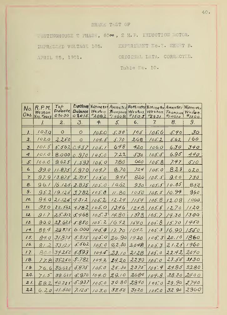
BRAKE TEST OF
mSTINGHOUSE 2 PHASE, Mm, 2 H. P. INDUCTION MOTOR.
IMPRESSED VOLTAGE 105. EXPERIMENT No. 3. SHExT B.
APRIL 25, 1901. ORIGINAL DATA. CORRECTED.
Table No. 10.
l 1
No.
UPS.
CD O tyf
n. r. n.Weston
To/>
fo JO
foatto/n
Balanceo to/S
i w( r i rtc. [tf
We ii<i nAm/ij-ctt)',
"ffaotv/jsdn
"Woo 8
r»oxt/ //e'er ionme f<r
We i ton
J/
/\>riniGi€)' Y&fffy &tr
We ifo // .
#156
1o<c
.
O T 0. D
,
O. QJ.
/. /oj.a 7oSO S.30 70S /OS* 6 S 76 JO2. /OZ.O Z.zso /0<f. S S.70 208 /as. 2 S.62 / 60
J. /OA S o.i-J/ /OS. / 6f78 ^20 /6 6.0 6.30 3<?o
/OA S-OQQ 0.370 /0S.6 7.22. S36 /OSS 6.9s 440
s. 16 6.6 9. 62 S /.S93 I6 6~. 7. 86 <36o /os. 8 7*7 S~/0
G 39-Q //. 87S 7 970 /o<?.7> &.?Q ?z</ /OS. 8.Z3 6267 37 9 /3.Q7S Z.3/S /oS.O 3.7S 826 /AS. S 9.0 6 730
8- 9 6V 76 Jis 2-873' /oS.d /0.62 936 /6S.S /0.0s
3 .2 /9. /2 S 3.782 /oS6 //8a / oS~6 /as. s 7o.9t 36o
/o. 9f. Q 2/.US -f.3/ 2 /dS2 /Z.2? 7/S-4 /as. 6 /060
// 33.0 2Z.S6Z 1-782 / 0S.0 7J.?6 /24& /dS.S /1.76 //20
U. 9/7 &j:j/z <Tf 68 /ocT. 3 /<?.8o /3?8 /OS? 7<?.dd 7300/J. Qo.Q 27. 625' s.sso /dS. 2 76*72 /S~<?6 /oS. S /S~.70 /<?s~o
/+ 884 £9. J7S 6. OOQ 70S.0 /7 7o 76-72 /dS.3 /690 /SsfO
IS. 8<7.o J/.87S S. 87S /d^o 2o. So /92a /dS. 3 2o. /0 786o/6. Q/.Z SJ./2S S<f62 /fiS. Z2.do 26¥g / 6 S3 2/-ZS /960
17 86-6 3f-ZS6 <rS93 l&f, s 33./
6
Z/Z8 /as c 22 Zofo/e. 7ZP> zS2fo S.782 /o^.z 2230 /a>s. Z3.J~S 2/30
/B >6. 6 36.6ZS S~.87S 7dS~.0 ZS.Jo 237S- /os.f 2i.8S 2280ZO. y/.s~ 38.626- d:97o 'o<?.0 %9JO Z684 /o<9>g 28.3o Z?ooZ 1. 58.Z <7d. 24 f d~937 /aS.6 30.80 / (ISO 29-96 £7<?o
zz 6. 2.0 4/. S66 f./ZS* 3J. So ^6 26 /dS.C J2.9a 2360
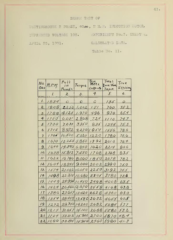
BRAKE TEST OF
WESTINGHOUSE 2 PHASE, 60c©, 2 H. P. INDUCTION MOTOR
IMPRESSED VOLTAGE 105. EXPERIMENT No. 3. SHEET
APRIL 25, 1901. CALCULATED DATA.
Table No. 11.
No-
Obs 1
ro 1
1
inFooncL 5,
~Tyl>P
Writs. fro*
1. Z. T. s. 6
.
/. /834 o o O
Z, /SoQ /J-/ 7bo
J. 77 88 4-JZf 7> 970 -f96 Q7o 6S.<?
6.63/ 2.868 7Z<7 i / to 74-7
s. 7730 7.0 3/ SJS I3<?4 7J-.3
6. / 7/f 2.97
Z
f.Z70 / Q3~4 733~6 78.6
7 /o.3~oo cT.dlo /zzo I78Q 78-6
8 / 67O 72.2.30 J3 9Z ZO/ 78-^
9. 76<?o 7f.SfO 6SfO 76ZO ZZ7<? 80.6
/o. 70 Jd /JT.87Z 77 68 1368 83.S// /6Z2 76.780 Q.06O / 8J~0 Z6 78 78-1
IZ. /6of 78.8ff 9.600 ZOoz Z99 7S.0
13. Jjr/f Z/.68X /O.66~0 zzso J/9Z 73.SIf. 74-98 70. 680 2.3*7
3~3780 73.6
13. 7<?<?9 / /. 73~o Z<?9 8 <70o8 63.S/6. 792<t Z6.S61 7Z.6/Q Z6~3~Q i/6g 63.6
11 /J86 Z7-637 734Z o H6Z S 4-360 63.
18. 7JJ~-? I3.4~S6 2~6>3Z 466'3~ 60S(9. 7Z7Z /^.zoo Z63Z £7720. 72/
7
37.637 Z688 3~3~6o S3.Z
Z 1. 7/ of 33.3/ % /d'906 Z7 0o SQ7o21. 70QO 33.373 73~.93~o JLf60 S9Qo
BRAKE TEST OF
V/ESTINGHOUSE 2 PHASE, 60co, 2 H. ?. INDUCTION MOTOR.
IMPRESSED VOLTAGE 105. EXPERIMENT No.?. SHEET E,
APRIL 25, 1901. CALCULATED DATA.
Table No. IS.
No.
OhS.
P
Y
? bin f J 3 in f Tcos f
/. z. 3. s. 6.
1. S~3~7 6./R3~ 73°Z3' 6. .953 s~<z z o.$dZ 3~96 0.fd~6 63°<7S' 6. 8Q2 Z.3~6
J. 683 0.666 f^V/' 0.71S f.fiZ 4-3Z73'8 0.699, 44*76' a. 7/6 oT/6 3~.0<?
s. QZ6 0.731 <?Z°S6' 7). 08/ 3~.3/ ifJO
6. 9/3 0. 7.93 rV\lZ' 0.609 3~.Z8 6.88
7 993 /\.<f<T7 J~.ZO 7878, //2>7 O.SZ6 V'8 0S63 7T.97 Q.80
9. /Z39 0,6?9 3/°d'3' 6.SZ f\ 6.fZ /o-oz
10. /ZQ7 16° 6' 07733 s.ss 77.00
II. 7f/Z 17° 0.f63~ 6.ZS /'.So
/3~d~8 n.&Sdr 2?°<74' 6,<77J~ 6.86 73. 7 6
Id. /73C a 890 17° 7' 7.47 /<?.60
/<? 7360 Q.8W 27°4</' 7>.463~ 8-2f sj:63~
IS, Z/ 30 n.Qfio Z3°Z7' 0.47f 3.9Z /8<?o
lb. 3.338 6.ft7?\ 0.4?
A
76. 60 /9.S0
11 2??o 7).9,72 0.4JQ 77.38 2/./ 7/8. ZS~6Z 7). ®7o 23°& 7)f9Z 72. 08 2/.<70
19. 2730 o.aon 29°76' a. <796 72,88 ZZ.J3-
zo. 3/ /& 0.86 3 36°Z\6 0.3~6S J3-.<7Z 26*74
z / VZ/O o.8s.9 D. S77 76.02 26.98zz Jd~6o o.s<r<r 37*W 0.^78 /7-7f Z3.r0


We si//j<j/ia use. JL Phase, 6 Q oo, Z>H.R Itjduntie // fi/o to r.
EUGENE DIETZGEN CO.. CHICAGO.
Af>ri) IJ, 19%
I
EUGENE DIETZGEN CO., CHICAGO.
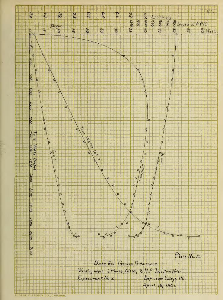
Pl&te No. JO,
fira/ielest. Gcene.r&\ ferfor/nonce.
We s-titfj /jOi/se Z Phase , 60 00;
Z> H.P. Induct/a/j f^otaf.
Ex/=er//7?e/7 T Ac. 2. Jnprzssed Vo)taje 110.
A/>ri) I8} /30 J.
EUGENE DIETZGEN CO.. CHICAGO.
EUGENE DIETZGEN CO., CHICAGO.

EUGENE DIETZGEN CO., CHICAGO.
EUGENE DIETZGEN CO., CHICAGO.

wm * - * .* * r + , * mr- f5 ~ * if
w^M^ W/fflr^-- /F^f^A IvfaR^i^H^\ ij^fv^
4.
f ,
-#-
# - 4 #
Ufa
I
*,
+ * +
5 s(fc
~ ~ * ..'
*
# # #. #; #' ^ ^ #
^ I * I ^ ^ ^ I_^ If I -f 4 # I I I
^ +
mJ- JL. ,JL^
:
^ *
IP -i^P #
^> - * # # m5i lw/ .JK^Ti \i/frMxC\\uy.
^ f # * f #

* m'4 : * f f
"4
# * .# .+ * *- ^ * * *
+ - * * + + + + 4 * • * t + * *"!
i
^ ^ JL
liirfiiiiiiiiii
J< f-i-4 ' * # + * fr.:;:
i& ^ # * * #
Hi
# #
* * * T ^r-
T- IP
^f1 1p : ;'
7:^^>^ I;,,
ij/kj ' ^ j; ^.
i ^ '
^ ^ ^I # # # ^ #t * * * #
& ^ ^ ^ ^dk' *t ' ' JL
# #| # # ^ # ^ * #
Jr . Jt;
^jL. .- JL
J» -a A Jk Jit JL ^ JL Jk-f r- t1- f t- *• 5^ t
/ ^^^^1W^^su^wi )^i|^7 ^^J^' -yk .
;' '^J^ 1^
- JL- +* +
# # 4- -f- f ^ ^ * f +f- * # f # # * * * * * *?
:
M, 7
# I * ^ *
p ^ ^r- r^ ^ i ' ^* T )T T
:* * i f • # #