Embed Size (px)
Citation preview
Three-Phase AC machines
Three-Phase Wound Rotor Induction Motors
Resource 6
Three-Phase AC Machines Resource 6
Aim
Three-Phase Wound Rotor Induction Motors
• To understand the construction, operation and performance of a Three-Phase Wound Rotor Induction Motor
Objectives
Three-Phase AC Machines Resource 6
• To be able to describe the construction of a three-phase wound rotor induction motor
• To be able to describe the operation of a three-phase wound rotor induction motor
• To be able to describe the performance of a three-phase wound rotor induction motor
Three-Phase Wound Rotor Induction Motors
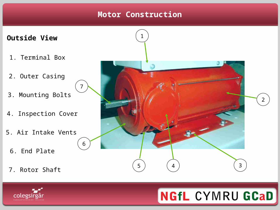
Motor Construction
1. Terminal Box
2. Outer Casing
6. End Plate
4. Inspection Cover
7. Rotor Shaft
1
2
3
6
7
5. Air Intake Vents
5
3. Mounting Bolts
4
Outside View
Motor Construction
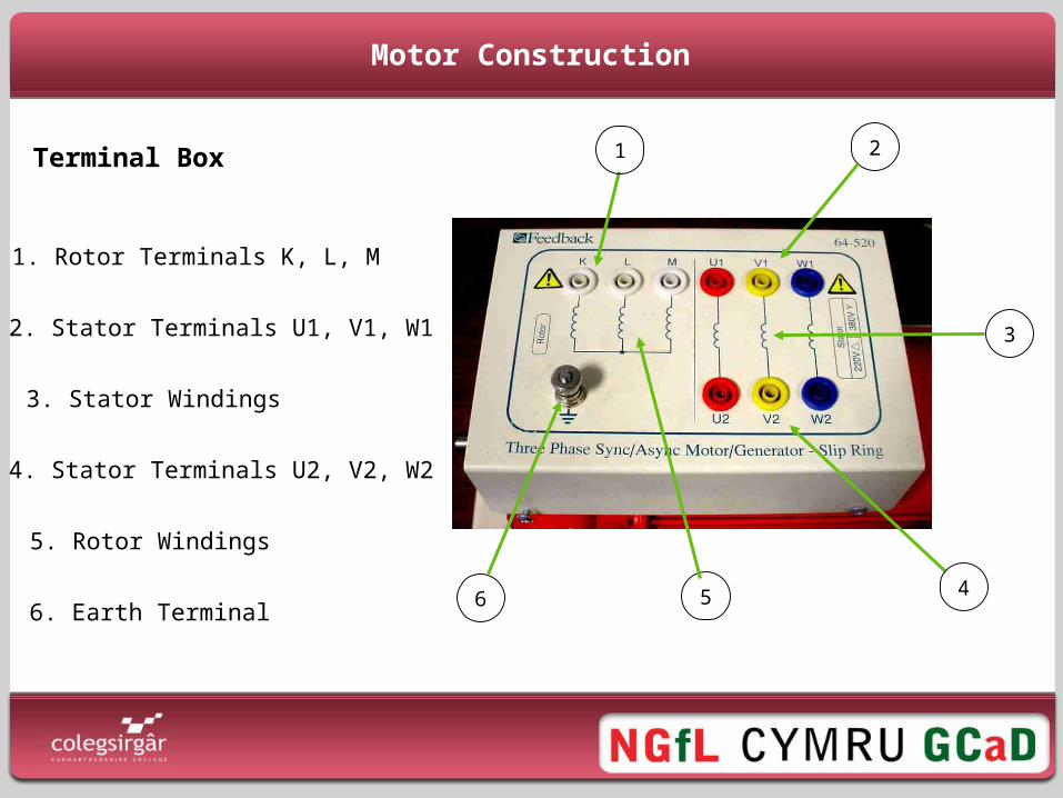
Terminal Box
1. Rotor Terminals K, L, M
5. Rotor Windings
3. Stator Windings
6. Earth Terminal
1 2
3
6
4. Stator Terminals U2, V2, W2
5
2. Stator Terminals U1, V1, W1
4
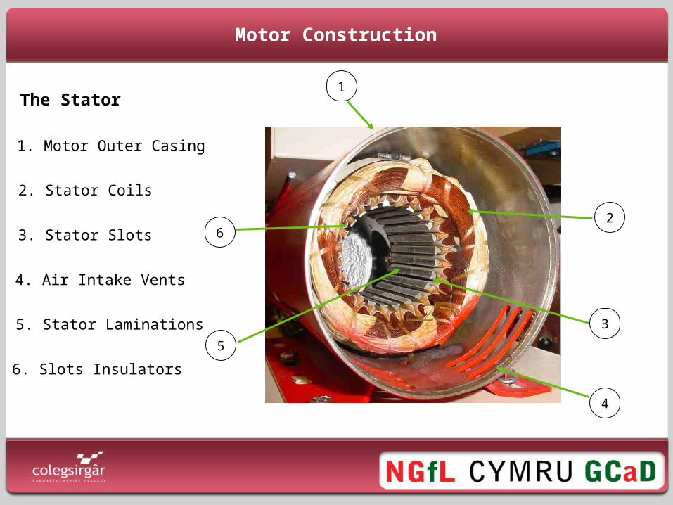
Motor Construction
1. Motor Outer Casing
2. Stator Coils
3. Stator Slots
5. Stator Laminations
6. Slots Insulators
1
2
3
5
6
4. Air Intake Vents
4
The Stator
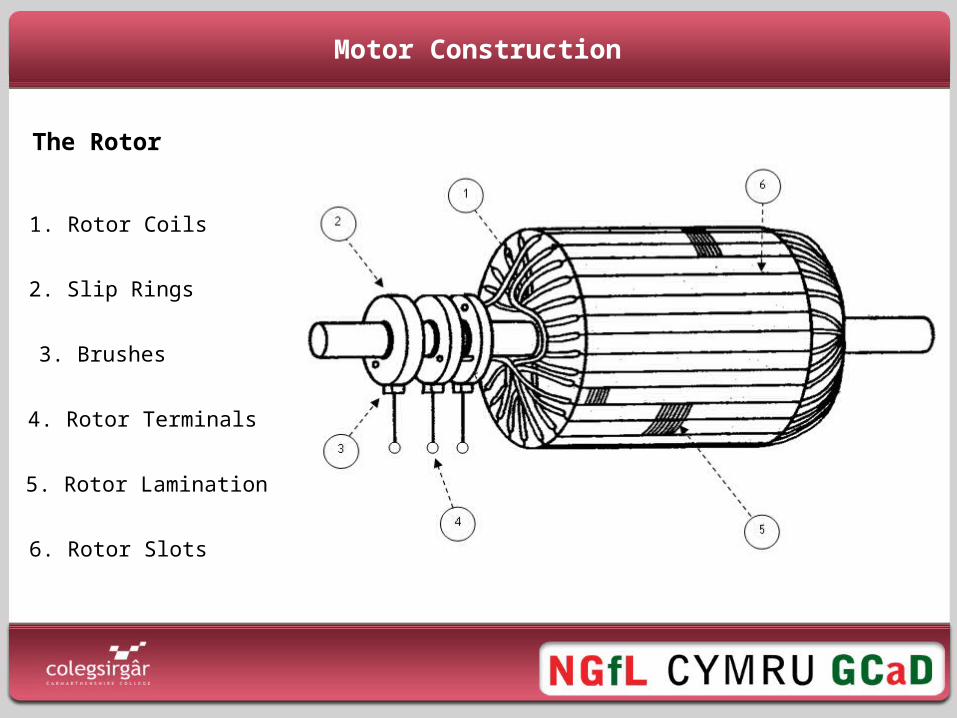
Motor Construction
1. Rotor Coils
2. Slip Rings
3. Brushes
4. Rotor Terminals
5. Rotor Laminations
6. Rotor Slots
The Rotor
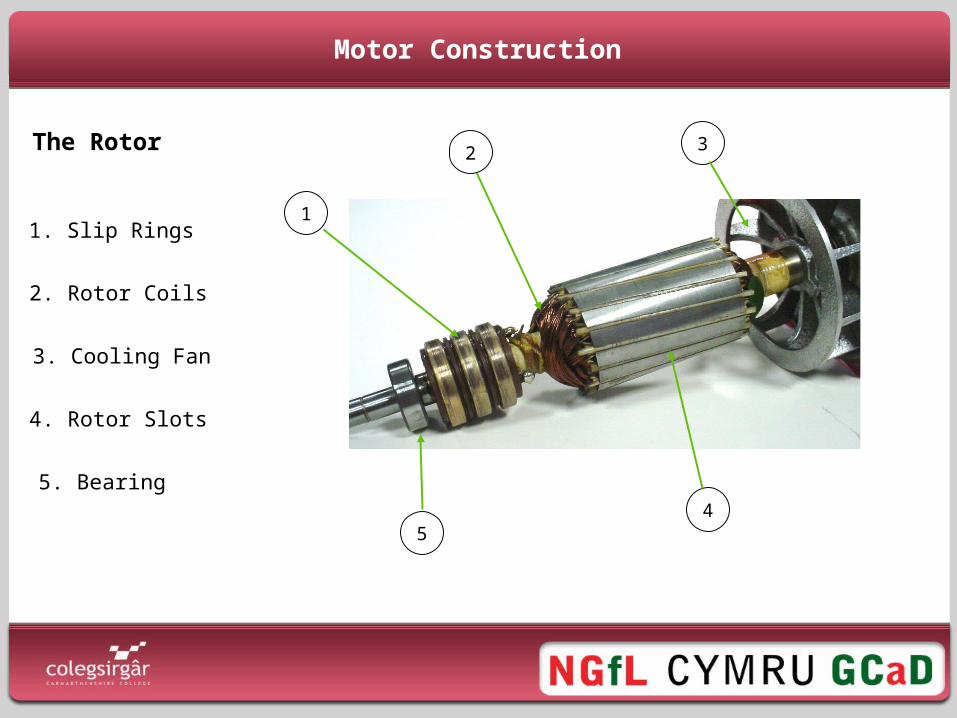
Motor Construction
2. Rotor Coils
1. Slip Rings
3. Cooling Fan
4. Rotor Slots
5. Bearing
2
1
3
54
The Rotor
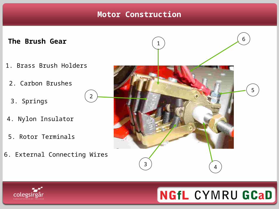
Motor Construction
2. Carbon Brushes
1. Brass Brush Holders
3. Springs
5. Rotor Terminals
6. External Connecting Wires
1
5
4
6
2
4. Nylon Insulator
3
The Brush Gear
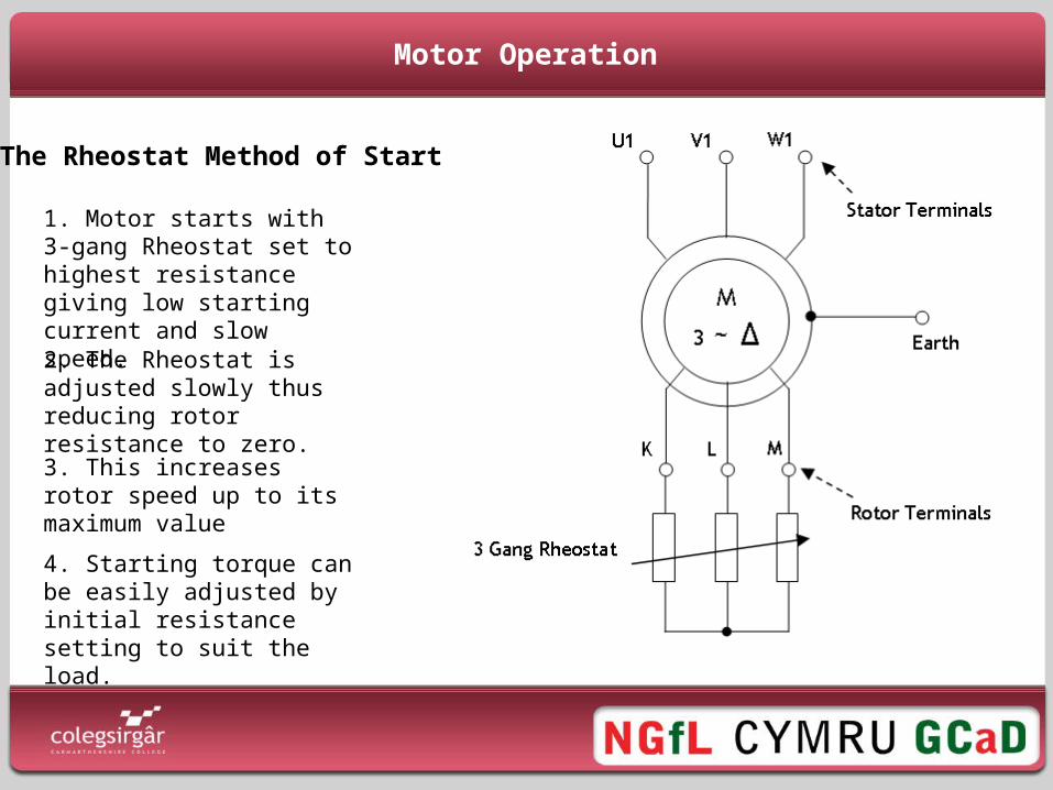
Motor Operation
1. Motor starts with 3-gang Rheostat set to highest resistance giving low starting current and slow speed.
The Rheostat Method of Starting
2. The Rheostat is adjusted slowly thus reducing rotor resistance to zero.3. This increases rotor speed up to its maximum value
4. Starting torque can be easily adjusted by initial resistance setting to suit the load.
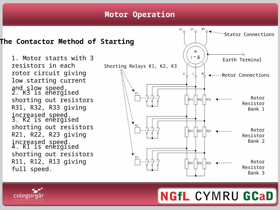
Motor Operation
1. Motor starts with 3 resistors in each rotor circuit giving low starting current and slow speed.
The Contactor Method of Starting
Earth Terminal
Stator Connections
Rotor Connections
Rotor Resistor Bank 1
Shorting Relays K1, K2, K3
Rotor Resistor Bank 2
Rotor Resistor Bank 3
2. K3 is energised shorting out resistors R31, R32, R33 giving increased speed.3. K2 is energised shorting out resistors R21, R22, R23 giving increased speed.4. K1 is energised shorting out resistors R11, R12, R13 giving full speed.
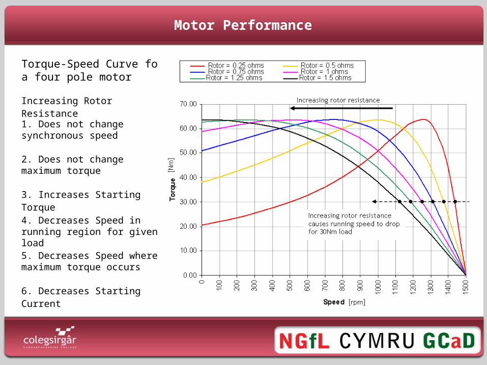
Motor Performance
Torque-Speed Curve for a four pole motor
Increasing Rotor Resistance
6. Decreases Starting Current
3. Increases Starting Torque
4. Decreases Speed in running region for given load
5. Decreases Speed where maximum torque occurs
1. Does not change synchronous speed
2. Does not change maximum torque