Embed Size (px)
Citation preview

Beginner’s Guide to SolidWorks 2008
Alejandro Reyes, MSME Certified SolidWorks Professional and Instructor
SDC
Schroff Development Corporation
www.schroff.com
www.schroff-europe.com
PUBLICATIONS
Copyrighted Material
Copyrighted
Material
Copyrighted Material
Copyrighted
Material
Beginner’s Guide to SolidWorks 2008
7
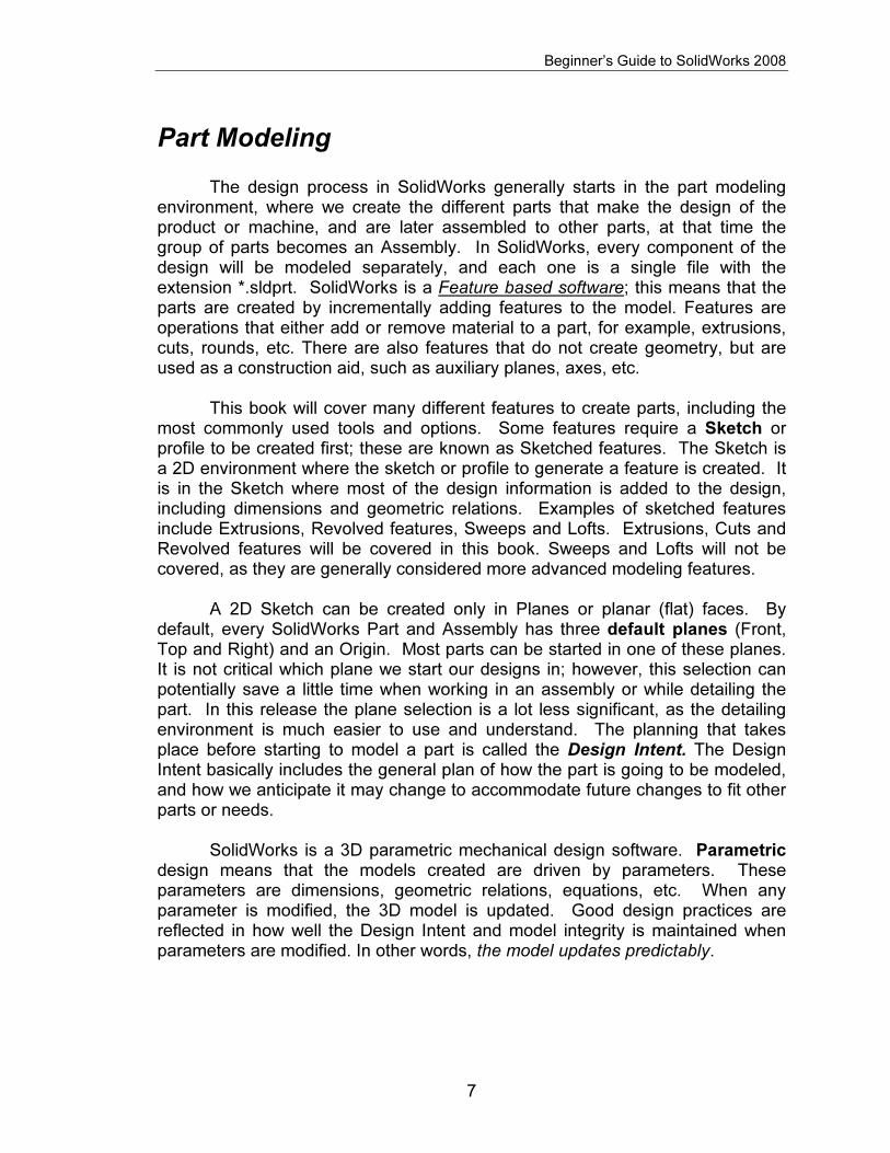
Part Modeling The design process in SolidWorks generally starts in the part modeling environment, where we create the different parts that make the design of the product or machine, and are later assembled to other parts, at that time the group of parts becomes an Assembly. In SolidWorks, every component of the design will be modeled separately, and each one is a single file with the extension *.sldprt. SolidWorks is a Feature based software; this means that the parts are created by incrementally adding features to the model. Features are operations that either add or remove material to a part, for example, extrusions, cuts, rounds, etc. There are also features that do not create geometry, but are used as a construction aid, such as auxiliary planes, axes, etc. This book will cover many different features to create parts, including the most commonly used tools and options. Some features require a Sketch or profile to be created first; these are known as Sketched features. The Sketch is a 2D environment where the sketch or profile to generate a feature is created. It is in the Sketch where most of the design information is added to the design, including dimensions and geometric relations. Examples of sketched features include Extrusions, Revolved features, Sweeps and Lofts. Extrusions, Cuts and Revolved features will be covered in this book. Sweeps and Lofts will not be covered, as they are generally considered more advanced modeling features. A 2D Sketch can be created only in Planes or planar (flat) faces. By default, every SolidWorks Part and Assembly has three default planes (Front, Top and Right) and an Origin. Most parts can be started in one of these planes. It is not critical which plane we start our designs in; however, this selection can potentially save a little time when working in an assembly or while detailing the part. In this release the plane selection is a lot less significant, as the detailing environment is much easier to use and understand. The planning that takes place before starting to model a part is called the Design Intent. The Design Intent basically includes the general plan of how the part is going to be modeled, and how we anticipate it may change to accommodate future changes to fit other parts or needs.
SolidWorks is a 3D parametric mechanical design software. Parametric design means that the models created are driven by parameters. These parameters are dimensions, geometric relations, equations, etc. When any parameter is modified, the 3D model is updated. Good design practices are reflected in how well the Design Intent and model integrity is maintained when parameters are modified. In other words, the model updates predictably.

Copyrighted Material
Copyrighted
Material
Copyrighted Material
Copyrighted
Material
Beginner’s Guide to SolidWorks 2008
8
Notes:

Copyrighted Material
Copyrighted
Material
Copyrighted Material
Copyrighted
Material
Beginner’s Guide to SolidWorks 2008
9
The Housing

Copyrighted Material
Copyrighted
Material
Copyrighted Material
Copyrighted
Material
Beginner’s Guide to SolidWorks 2008
10
When we start a new design, we have to decide how we are going to model it. Remember that the parts will be made one feature or operation at a time. It takes a little practice to define the optimum feature sequence for any given part, but this is something that you will master once you learn to think of parts as a sequence of features. To help you understand how to make the Housing part, we’ll show a “roadmap” or sequence of features. The order of some of these features can be changed, but remember that we need to make some features before others. For example, we cannot round the corners if there are no corners to round! A sequence will be shown at the beginning of each part, and the dimensional details will be given as we progress.
In this lesson we will cover the following tools and features: creating
various sketch elements, geometric relations and dimensions, Extrusions, Cuts, Fillets, Mirror Features, Hole Wizard, Linear and Circular Patterns. For the Housing, we’ll follow the following sequence of features:
Base Extrusion Top Extrusion Fillets Inside Cut
Front boss Mirror Front boss Side boss Mirror Side boss
Front cut Side cut Screw hole Screw hole pattern
Top tapped holes Base hole Base holes pattern Mirror holes pattern
Copyrighted Material
Copyrighted
Material
Copyrighted Material
Copyrighted
Material
Beginner’s Guide to SolidWorks 2008
11
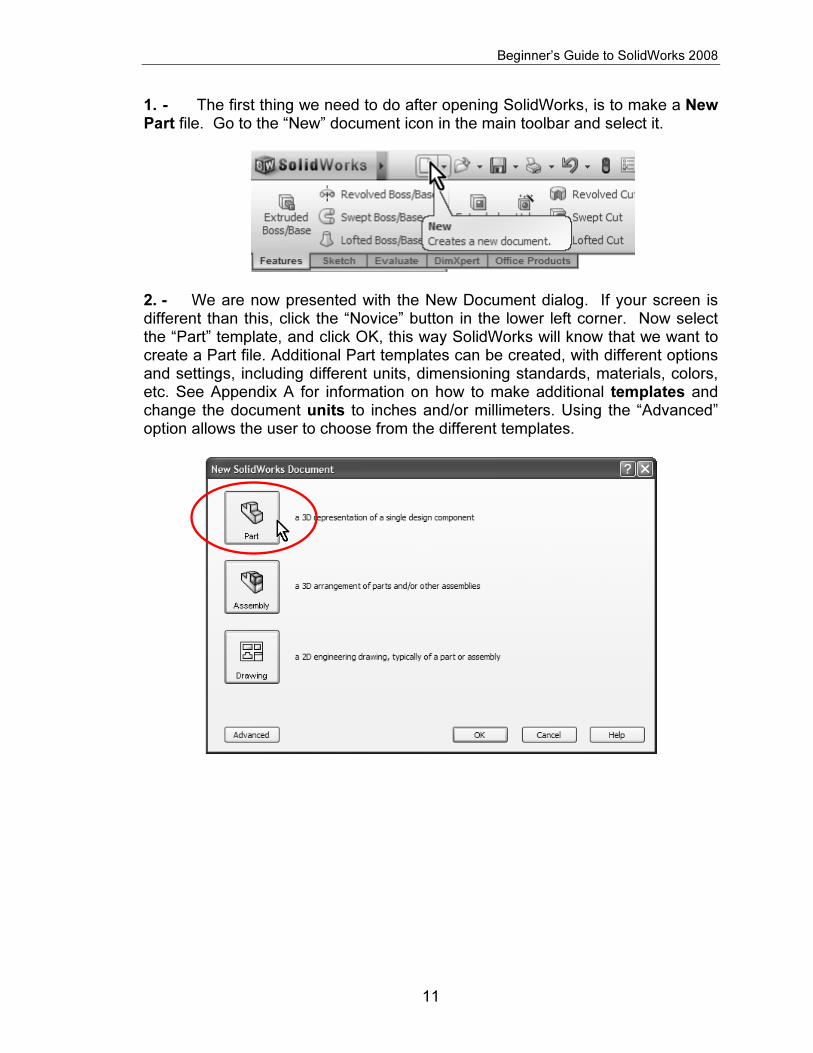
1. - The first thing we need to do after opening SolidWorks, is to make a New Part file. Go to the “New” document icon in the main toolbar and select it.
2. - We are now presented with the New Document dialog. If your screen is different than this, click the “Novice” button in the lower left corner. Now select the “Part” template, and click OK, this way SolidWorks will know that we want to create a Part file. Additional Part templates can be created, with different options and settings, including different units, dimensioning standards, materials, colors, etc. See Appendix A for information on how to make additional templates and change the document units to inches and/or millimeters. Using the “Advanced” option allows the user to choose from the different templates.

Copyrighted Material
Copyrighted
Material
Copyrighted Material
Copyrighted
Material
Beginner’s Guide to SolidWorks 2008
12
3. - Now that we have a new Part file, we have to start modeling the part, and the first thing we need to do is to make the extrusion for the base of the Housing. Select the “Extruded Boss/Base” icon from the Command Manager’s Features tab. SolidWorks will automatically start a new Sketch, and we will be asked to select the plane in which we want to start working. Since this is the first feature of the part, we will be shown the three standard planes (Front, Top and Right). Remember the sketch is the 2D environment where we draw the profile before creating an extrusion; in other words, before we make it “3D”.
4. - For the Housing, we’ll select the “Top Plane” to create the first sketch. We select the Top Plane, because we want to start modeling the part at the base of the Housing and build it up as was shown in the roadmap at the beginning of this chapter. Do not get too worried if you can’t figure out which plane to choose first; at worst, what you thought would be a Front view may not be the front; this is for the most part irrelevant, as the user is able to choose the views at the time of detailing the part in the 2D manufacturing drawing. Select the Top Plane from the screen and the view will be automatically rotated to a Top View.

Copyrighted Material
Copyrighted
Material
Copyrighted Material
Copyrighted
Material
Beginner’s Guide to SolidWorks 2008
13
What we have just done, is we created a new Sketch and are in the sketch environment now. This is where we will create the profiles that will be used to make Extrusions, Cuts, etc. SolidWorks gives us many indications, most of them graphical, to help us know when we are working in a Sketch.
a) The Confirmation Corner is activated in the upper right corner and displays the Sketch icon in transparent colors.
b) The Status bar shows “Editing Sketch”
in the lower right corner.
c) In the Feature Manager “Sketch1” is added at the
bottom just under “Origin”.
d) The part’s Origin is projected in the Sketch plane in red and the grid is visible.
e) The Sketch tab is activated in the Command Manager.
f) If the option is selected, the Sketch Grid will be displayed. This can be
easily turned on or off while in the Sketch environment, by Right-Mouse-Clicking in the graphics area and selecting the “Display Grid” option.
As the reader can see, SolidWorks gives us plenty of clues to help us know that we are working in a sketch. 5. - Notice that when we make the first sketch, SolidWorks rotates the view to match the plane that we selected. This is done only in the first sketch to help the
Copyrighted Material
Copyrighted
Material
Copyrighted Material
Copyrighted
Material
Beginner’s Guide to SolidWorks 2008
14
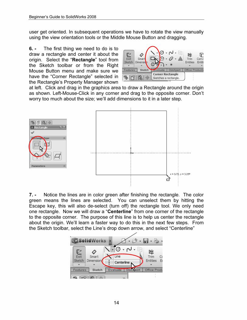
user get oriented. In subsequent operations we have to rotate the view manually using the view orientation tools or the Middle Mouse Button and dragging. 6. - The first thing we need to do is to draw a rectangle and center it about the origin. Select the “Rectangle” tool from the Sketch toolbar or from the Right Mouse Button menu and make sure we have the “Corner Rectangle” selected in the Rectangle’s Property Manager shown at left. Click and drag in the graphics area to draw a Rectangle around the origin as shown. Left-Mouse-Click in any corner and drag to the opposite corner. Don’t worry too much about the size; we’ll add dimensions to it in a later step.
7. - Notice the lines are in color green after finishing the rectangle. The color green means the lines are selected. You can unselect them by hitting the Escape key, this will also de-select (turn off) the rectangle tool. We only need one rectangle. Now we will draw a “Centerline” from one corner of the rectangle to the opposite corner. The purpose of this line is to help us center the rectangle about the origin. We’ll learn a faster way to do this in the next few steps. From the Sketch toolbar, select the Line’s drop down arrow, and select “Centerline”

Copyrighted Material
Copyrighted
Material
Copyrighted Material
Copyrighted
Material
Beginner’s Guide to SolidWorks 2008
15
8. - SolidWorks indicates that we will start or finish a line at an existing entity with yellow icons; when the cursor is near an endpoint, line, edge, origin, etc. it will “snap” to it. Click in one corner, click in the opposite corner as shown and press the Escape key to finish the Centerline command.
9. - Now we’ll add a “Midpoint” geometric relation between the centerline we just drew and the part’s origin. From the “Tools” menu, select “Relations, Add” or click in the “Add Relation” icon from the “Display/Delete Relations” drop-down icon. By adding this relation, the centerline’s mid point will coincide with the origin; this way the part will be centered about the origin which will be useful in future operations.
10. - The “Add Relations” Property Manager is displayed. The Property Manager is the area where we will make our selections and choice of options for most commands. Select the previously made centerline and the part’s origin by clicking on them in the graphics area (notice how they turn green and get listed under the “Selected Entities” box). Click on “Midpoint” under the “Add Relations” box to add the relation. Now the center of the line coincides with the Origin. Click on OK (the green checkmark) to finish the command. Click and drag one corner of the rectangle to see the effect of the relation. Notice the center of the line stays in the origin and the rectangle resizes about the center.

Copyrighted Material
Copyrighted
Material
Copyrighted Material
Copyrighted
Material
Beginner’s Guide to SolidWorks 2008
16
11. - We just added a geometric relation manually, and we also added geometric relations automatically when we drew the rectangle and the centerline in the previous step. SolidWorks allows us to graphically view the existing relations between sketch elements. Go to the “View” menu, “Sketch Relations” if not already activated, or from the “Hide/Show Items” drop down icon in the graphics area.
12. - Now we can see the geometric relations graphically represented by small blue icons next to the lines, arcs, etc. Notice that when we move the mouse pointer over a geometric relation icon, the entity or entities that share the relation are highlighted. NOTE: To delete a geometric relation select the relation icon in the screen and press the “Delete” key, or Right Mouse Click on the Geometric Relation icon and select “Delete”. (Do not delete relations at this time!)

Copyrighted Material
Copyrighted
Material
Copyrighted Material
Copyrighted
Material
Beginner’s Guide to SolidWorks 2008
17
The Sketch Origin defines the local Horizontal (Short red arrow) and local Vertical (Long red arrow) directions, this is important because we may be looking at the part in a different orientation, and vertical may not necessarily mean “up” on the screen. In SolidWorks we can add the following types of geometric relations between sketch entities:
Vertical with respect to the sketch vertical direction (Long red arrow in the origin)
Horizontal with respect to the sketch horizontal direction (Short red arrow in the sketch origin)
Coincident is when an endpoint touches another line, endpoint, model edge or circle.
Midpoint is when a line endpoint coincides with the middle of another line or model edge. A Midpoint relation implies its Coincident.

Copyrighted Material
Copyrighted
Material
Copyrighted Material
Copyrighted
Material
Beginner’s Guide to SolidWorks 2008
18
Parallel is when two or more lines have the same inclination.
Perpendicular is when two lines are 90 degrees from each other, like a vertical and horizontal lines. They don’t have to touch each other in order to be perpendicular.
Concentric is when two arcs or circles share the same center. Concentric can be also between a point or line’s endpoint and an arc or circle’s center.
Tangent is when a line and an arc or circle, or two arcs or circles are tangent to each other.
Equal is when two or more lines are the same length, or two or more arcs or circles have the same diameter.
Collinear is when two or more lines lie on the same line.
13. - The next step is to dimension the rectangle. Turn off the geometric relations display in the “View” menu “Sketch Relations” to avoid visual clutter in the screen. Click with the Right Mouse Button in the graphics area and select “Smart Dimension” or select the “Smart Dimension” icon from the Sketch toolbar. Notice the cursor changes adding a small dimension icon next to it to indicate the user the Smart Dimension tool is selected.
14. - Adding dimensions in SolidWorks is simple. Click to select the right vertical line and then click just to the right to locate the dimension. SolidWorks will show the “Modify” dialog box, where we can add the 2.625” dimension. Repeat with the top horizontal line and add a 6” dimension. As soon as the dimension value is accepted, the geometry updates to reflect the correct size.

Copyrighted Material
Copyrighted
Material
Copyrighted Material
Copyrighted
Material
Beginner’s Guide to SolidWorks 2008
19
NOTE: View the Appendix if you need to change the document’s units from millimeters to inches or vice versa. You can also override the units by adding “in” or “mm” at the end of the value in the Modify dialog box.
After dimensioning the lines, notice the lines changed from Blue to Black. This is the way SolidWorks indicates that the geometry is defined, meaning that we have added enough information (dimensions and/or geometric relations) to define the geometry in the sketch. The status bar also shows “Fully Defined”. This is the preferred state before creating a feature, since there is no information missing and the geometry can be accurately described.

Copyrighted Material
Copyrighted
Material
Copyrighted Material
Copyrighted
Material
Beginner’s Guide to SolidWorks 2008
20
A sketch can be in one of several states; the three main ones are:
• Under Defined: (BLUE) Not enough dimensions and/or geometric relations have been provided to define the sketch. Sketch geometry is blue and can be dragged with the mouse.
• Fully Defined: (BLACK) The Sketch has all the necessary dimensions and/or geometric relations to completely define it. This is the desired state. Fully defined geometry is black.
• Over Defined: (RED) Redundant and/or conflicting dimensions and/or geometric relations have been added to the sketch. If an over-defining dimension or relation is added, SolidWorks will warn the user. If an over-defining geometric relation is added, delete it or use the “Edit” menu, “Undo”
command or the “Undo” icon . If an over-defining dimension is added, the user will be offered an option to cancel it.
15. - Now that the sketch is fully defined, we will create the first part of the housing; this is where we go from the 2D Sketch to a 3D feature. Click in the Features tab in the Command Manager and select the “Extrude” icon, or click in the “Exit Sketch” icon in the Sketch toolbar. In the second case SolidWorks remembers that we wanted to make an Extrusion, and displays the Extrude command’s property manager. Notice that the first time we create a feature, SolidWorks changes to an Isometric view, and gives us a preview of what the feature will look like when finished.

Copyrighted Material
Copyrighted
Material
Copyrighted Material
Copyrighted
Material
Beginner’s Guide to SolidWorks 2008
21
Select the options indicated in the “Extrude” command to make the extrusion 0.25” thick. To finish the command, select the OK button.
16. - After the first extrusion, notice that “Extrude1” has been added to the Feature Manager. The confirmation corner is no longer active. The status bar now reads “Editing Part” to alert us that we are now editing the part and not the sketch.
If we expand the Extrude1 feature in the Feature Manager by clicking on the “+” on the left side of it, we see that “Sketch1” has been absorbed by the “Extrude1” feature.
17. - The second feature will be similar to the first one but with different dimensions. To create the second extrusion, we need to make a new sketch. When we select the Extrude or Sketch icon, SolidWorks gives us a yellow message in the Property Manager asking us to select a Plane or a planar (flat) face. We’ll select the top face of the previous extrusion for the next feature. (If a Plane or flat face is pre-selected, the Sketch opens immediately in that Plane/face.)

Copyrighted Material
Copyrighted
Material
Copyrighted Material
Copyrighted
Material
Beginner’s Guide to SolidWorks 2008
22
18. - To help us get oriented, we will switch to a Top View to see the part from the top. In SolidWorks the user is free to work in any orientation, as long as he/she is able to see what they are doing. Re-orienting the part helps the new user get used to 3D in a more familiar way by looking at it in 2D.
19. - For the second extrusion, we’ll use the “Center Rectangle” command. Activate the “Rectangle” tool, and select the “Center Rectangle” option from the Rectangle’s Property Manager. First click in the Origin to start the rectangle, and click again on the edge of the first extrusion to finish it. Notice the yellow Coincident icon as the pointer is in the origin and then on the edge. This way we’ll automatically add coincident relations and the rectangle will be centered about the origin.

Copyrighted Material
Copyrighted
Material
Copyrighted Material
Copyrighted
Material
Beginner’s Guide to SolidWorks 2008
23
20. - Dimension the rectangle 4” wide as shown. This will fully define the sketch.
21. - We are now ready to make the second extruded feature. Select the Extrude or Exit Sketch icon as we did in step 15 and extrude it 3.5”. From the Standard Views icon, select the Isometric view to see the preview of the second extrusion. Click on OK to complete the command.
22. - The next step is to round the edges of the two extrusions. To do this, we will select the Fillet command. This is what’s called an “Applied Feature”; we don’t need a sketch to create it, and it’s applied directly to the solid model. Select the “Fillet” icon from the Features toolbar; make sure the “Manual” mode is selected. By default, “Constant Radius” type is selected. We’ll change the radius to 0.25” and select the corners indicated with the preview. SolidWorks highlights the model edges when we place the cursor on top of them to let us know that we’ll select them if we click on them. Click on OK when done selecting edges to complete the command.

Copyrighted Material
Copyrighted
Material
Copyrighted Material
Copyrighted
Material
Beginner’s Guide to SolidWorks 2008
24
TIP: If an edge or face is mistakenly selected, simply click on it again to de-select it. You can rotate the model using the arrow keys or click and drag with the Middle-Mouse-Button if you cannot see an edge to select it.

Copyrighted Material
Copyrighted
Material
Copyrighted Material
Copyrighted
Material
Beginner’s Guide to SolidWorks 2008
25
23. - Repeat the fillet command to add a 0.125” fillet at the base of the Housing. By selecting the faces SolidWorks rounds all the edges of the faces selected.
Finished fillets.
In SolidWorks we can change the display of tangent edges (The edges where two tangent faces meet) selecting the “View” menu, “Display” and select the display option wanted: Visible, as Phantom or Removed. Explore the different options to find the one you feel more comfortable with. In this book we used the Phantom lines for clarity.
Copyrighted Material
Copyrighted
Material
Copyrighted Material
Copyrighted
Material
Beginner’s Guide to SolidWorks 2008
26
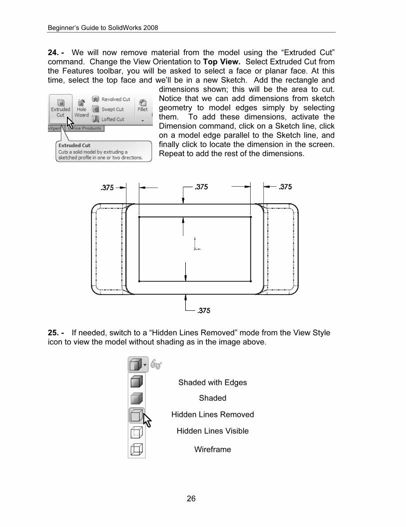
24. - We will now remove material from the model using the “Extruded Cut” command. Change the View Orientation to Top View. Select Extruded Cut from the Features toolbar, you will be asked to select a face or planar face. At this time, select the top face and we’ll be in a new Sketch. Add the rectangle and
dimensions shown; this will be the area to cut. Notice that we can add dimensions from sketch geometry to model edges simply by selecting them. To add these dimensions, activate the Dimension command, click on a Sketch line, click on a model edge parallel to the Sketch line, and finally click to locate the dimension in the screen. Repeat to add the rest of the dimensions.
25. - If needed, switch to a “Hidden Lines Removed” mode from the View Style icon to view the model without shading as in the image above.
Shaded with Edges
Shaded
Hidden Lines Removed
Hidden Lines Visible
Wireframe

Copyrighted Material
Copyrighted
Material
Copyrighted Material
Copyrighted
Material
Beginner’s Guide to SolidWorks 2008
27
26. - In this feature, we will round the corners in the sketch using a Sketch Fillet. We can add the fillets as applied features like before, but in this step we chose to show you how to round the corners in the Sketch before making the “Extruded Cut” feature. Select the “Sketch Fillet” icon from the Sketch toolbar.
Set the fillet radius to 0.15”, and click on the corners of the sketch lines as indicated to round them. After clicking on all 4 corners, click OK to finish the Sketch Fillet command. Notice that only one dimension is added. The reason is that SolidWorks adds an equal relation from each fillet to the one dimensioned fillet.
27. - Now we select the Extruded Cut icon or Exit Sketch to remove the material. Opposite to the Boss Extrude feature that adds material, the Cut feature, as its name implies, removes material from the model.

Copyrighted Material
Copyrighted
Material
Copyrighted Material
Copyrighted
Material
Beginner’s Guide to SolidWorks 2008
28
Make the cut 3.5” deep using the options shown in the next image. Change the view to Isometric and Shaded with Edges (Step 25) to better visualize the effect.
28. - In the next step we will add a simple round boss to the front of the Housing. Switch to a Front View, and make a sketch on the front face. Select the “Sketch” icon, and then click in the front-most face. Or, the reverse order: select the face first, and then click in the “Sketch” icon.
29. - Select the “Circle” sketch tool …

Copyrighted Material
Copyrighted
Material
Copyrighted Material
Copyrighted
Material
Beginner’s Guide to SolidWorks 2008
29
… and draw and dimension a circle approximately as shown next. To dimension the circle, select either the center of the circle or its perimeter and the top edge of the housing.
30. - To locate the circle in the center of the part, we will add a Vertical Relation between the center of the circle and the part’s origin. SolidWorks allows us to align sketch elements to each other or to existing model geometry (edges, faces, vertices, etc.). From the Right Mouse button menu, select “Add Relations”, and select the circle’s center (Not the perimeter!) and the origin. Click on Vertical and OK to finish.
Copyrighted Material
Copyrighted
Material
Copyrighted Material
Copyrighted
Material
Beginner’s Guide to SolidWorks 2008
30
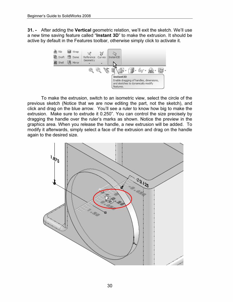
31. - After adding the Vertical geometric relation, we’ll exit the sketch. We’ll use a new time saving feature called “Instant 3D” to make the extrusion. It should be active by default in the Features toolbar, otherwise simply click to activate it.
To make the extrusion, switch to an isometric view, select the circle of the
previous sketch (Notice that we are now editing the part, not the sketch), and click and drag on the blue arrow. You’ll see a ruler to know how big to make the extrusion. Make sure to extrude it 0.250”. You can control the size precisely by dragging the handle over the ruler’s marks as shown. Notice the preview in the graphics area. When you release the handle, a new extrusion will be added. To modify it afterwards, simply select a face of the extrusion and drag on the handle again to the desired size.

Copyrighted Material
Copyrighted
Material
Copyrighted Material
Copyrighted
Material
Beginner’s Guide to SolidWorks 2008
31
32. - The next step is to create an identical extrusion on the other side of the Housing. To make it we’ll use the “Mirror” command that will make an identical 3D copy of the extrusion we just made. Switch to an Isometric view to help us visualize the Mirror’s preview and make sure we are getting what we want.
33. - Select the Mirror command from the Features toolbar.
34. - From the Mirror Property Manager, we have to make two selections. The first one is the Mirror Face/Plane and the second is the feature(s) we want to make a mirror from. The face or plane that will be used to mirror the feature has to be in the middle between the original feature and the desired mirrored copy. Making the first extrusion centered about the origin causes the Front plane to be in the middle, making it the best option to use as the Mirror Plane. To select the Front plane, (make sure the Mirror Face/Plane selection box is highlighted; this means that this is the active selection box) click on the “+” sign next to “Part1” to the right of the Property Manager to reveal a fly-out Feature Manager from which we can select the Front Plane.

Copyrighted Material
Copyrighted
Material
Copyrighted Material
Copyrighted
Material
Beginner’s Guide to SolidWorks 2008
32
35. - After selecting the Front Plane from the fly-out Feature Manager, SolidWorks automatically activates the “Features to Mirror” selection box (now highlighted), and if not already selected, select the last extrusion to mirror it. Notice the preview and click OK. Rotate the view to inspect the mirrored feature.
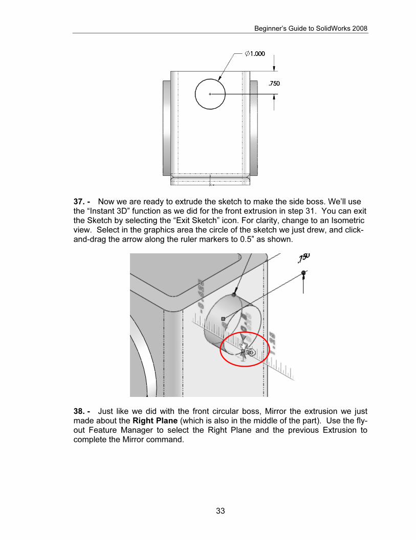
36. - In the next step we’ll add the small boss at the right side of the Housing. Switch to a Right View, click in the Sketch icon and select the right most face. Draw a circle and dimension as shown. Remember to add a Vertical Relation between the center of the circle and the origin as we did in step 30.
Copyrighted Material
Copyrighted
Material
Copyrighted Material
Copyrighted
Material
Beginner’s Guide to SolidWorks 2008
33
37. - Now we are ready to extrude the sketch to make the side boss. We’ll use the “Instant 3D” function as we did for the front extrusion in step 31. You can exit the Sketch by selecting the “Exit Sketch” icon. For clarity, change to an Isometric view. Select in the graphics area the circle of the sketch we just drew, and click-and-drag the arrow along the ruler markers to 0.5” as shown.
38. - Just like we did with the front circular boss, Mirror the extrusion we just made about the Right Plane (which is also in the middle of the part). Use the fly-out Feature Manager to select the Right Plane and the previous Extrusion to complete the Mirror command.

Copyrighted Material
Copyrighted
Material
Copyrighted Material
Copyrighted
Material
Beginner’s Guide to SolidWorks 2008
34
39. - Now we’ll make the circular cut in the front of the Housing. Switch to a Front View and create a sketch on the front most face. Draw a circle using the Circle tool and dimension it 2.250” Diameter. To center the circle in the circular extrusion, add a “Concentric Relation” selecting the circle and the round edge. Click OK to finish the “Add Relations” command.

Copyrighted Material
Copyrighted
Material
Copyrighted Material
Copyrighted
Material
Beginner’s Guide to SolidWorks 2008
35
40. - Now that the circle is concentric with the boss, make a cut with the “Through All” option, selecting the “Extruded Cut” icon from the Features toolbar; this will make the cut go through the entire part regardless of its size.
41. - We will now make a hole in the boss added in step 37 for a shaft. Switch to a Right View and add a sketch on the circular boss’ face. We want the hole to be concentric with the boss. To do this we can add the circle and add concentric relation as we just did; however, this is a two step process. Instead, we will do it in one step: Select the “Circle” tool icon from the Sketch toolbar and before drawing the circle, move the cursor and rest it on top of the circular edge as shown, until the center of the circular edge is revealed. DO NOT CLICK ON THE EDGE. This highlight works only if you have a drawing tool active like Line, Circle, Arc, etc. This technique can be used to reveal any circular edge’s center.

Copyrighted Material
Copyrighted
Material
Copyrighted Material
Copyrighted
Material
Beginner’s Guide to SolidWorks 2008
36
42. - Start drawing the circle at the center of the boss to automatically capture a concentric relation with the boss and dimension it 0.575” diameter. Now the sketch is fully defined.
43. - Since this hole will be used for a shaft, we’ll add a Bilateral tolerance to the dimension. Select the 0.575” dimension in the graphics area, and from the dimension’s Property Manager, under “Tolerance/Precision” select “Bilateral”. Now we can add the tolerances. Notice that the dimension changes immediately in the graphics area. This tolerance will be transferred to the Housing’s drawing later on. If needed, tolerances can also be added later in the drawing.

Copyrighted Material
Copyrighted
Material
Copyrighted Material
Copyrighted
Material
Beginner’s Guide to SolidWorks 2008
37
44. - Now we can make a Cut with the “Through All” option using the “Extruded Cut” command, or using the Instant 3D feature. To use Instant 3D to make a cut, click in the “Exit Sketch” icon and change to an Isometric view for clarity, and just like we did for the Extrusion, select the circle and click-and-drag the arrow into the part. You’ll see how the part is cut as the arrow is dragged. The only disadvantage to cutting this way is that the “Through All” option is not available while dragging.
45. - For the next feature we’ll make a ¼”-20 tapped hole in the front face. SolidWorks provides us with a tool to automate the creation of simple, Countersunk and Counterbore holes, tap and Pipe taps by selecting a fastener size, depth and location. The “Hole Wizard” command is a two step process: in the first step we define the hole’s type and size, and in the second step we define the location of the hole(s). To add the tapped hole, switch to a Front View. The Hole Wizard is a special type of feature that uses 2 sketches that are automatically created for you, so there is no need to add a sketch first, it works like an applied feature.

Copyrighted Material
Copyrighted
Material
Copyrighted Material
Copyrighted
Material
Beginner’s Guide to SolidWorks 2008
38
First, select the front most face (where we want to put the tapped hole); if you have the “Instant 3D” active as we do here, you will see the feature’s dimensions and a pop-up transparent toolbar that allows us to edit the selected feature. We will not use this toolbar at this time; we can simply ignore it if we don’t need it.
After selecting the front face select the “Hole Wizard” icon from the Features toolbar. The order is very important, otherwise we’ll have a different behavior when we define the location of the hole and more work will be needed to complete the feature.
46. - When the “Hole Wizard” dialog is presented, we’ll define the hole’s type and size first. Select the “Tap” hole icon, “ANSI Inch” for Standard, “Tapped Hole” for Screw type and “¼-20” for Size from the drop down selection list. Change “End Condition” to “Up to Next” as indicated, this will make the tapped hole’s depth up to the next face where it makes a complete round hole.

Copyrighted Material
Copyrighted
Material
Copyrighted Material
Copyrighted
Material
Beginner’s Guide to SolidWorks 2008
39
47. - Now we are ready for the second step, to define the hole’s location. Click in the “Positions” tab at the top. Notice the “Sketch Point” tool is activated automatically. SolidWorks automatically added a point that locates the hole where we pre-selected the face, as we can see in the preview. In order to precisely locate the hole’s center, we will draw a Centerline starting at the right quadrant of the outer circular edge, and finishing at the same quadrant of the inner circular edge. The quadrants will be activated after selecting the Centerline tool, and touching (not clicking!) the circular edge. It can be any one of the quadrants; we just picked this one for the example.
Click for Start Click for End Finished Center line

Copyrighted Material
Copyrighted
Material
Copyrighted Material
Copyrighted
Material
Beginner’s Guide to SolidWorks 2008
40
The idea behind this technique is to make sure the hole is centered in the circular face. Now add a “Midpoint” relation using the “Add Relation” command and selecting the pre-existing point and the centerline we just made. Click OK to close the “Add Relations” dialog, and then click OK again to finish the Hole Wizard.
A quicker way to add the Midpoint relation is to Window-Select the “Point” and “Centerline”, and select “Midpoint” from the pop-up toolbar.
Now the Hole is located in the middle of the Centerline.
Copyrighted Material
Copyrighted
Material
Copyrighted Material
Copyrighted
Material
Beginner’s Guide to SolidWorks 2008
41
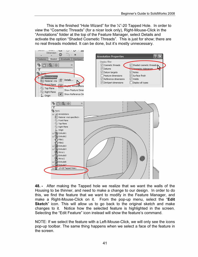
This is the finished “Hole Wizard” for the ¼”-20 Tapped Hole. In order to view the “Cosmetic Threads” (for a nicer look only), Right-Mouse-Click in the “Annotations” folder at the top of the Feature Manager, select Details and activate the option “Shaded Cosmetic Threads”. This is just for show; there are no real threads modeled. It can be done, but it’s mostly unnecessary.
48. - After making the Tapped hole we realize that we want the walls of the Housing to be thinner, and need to make a change to our design. In order to do this, we find the feature that we want to modify in the Feature Manager, and make a Right-Mouse-Click on it. From the pop-up menu, select the “Edit Sketch” icon. This will allow us to go back to the original sketch and make changes to it. Notice how the selected feature is highlighted in the screen. Selecting the “Edit Feature” icon instead will show the feature’s command. NOTE: If we select the feature with a Left-Mouse-Click, we will only see the icons pop-up toolbar. The same thing happens when we select a face of the feature in the screen.

Copyrighted Material
Copyrighted
Material
Copyrighted Material
Copyrighted
Material
Beginner’s Guide to SolidWorks 2008
42
49. - What we just did was to go back to editing the feature’s Sketch, just like when we first created it. Switch to a top view if needed for visualization. To change a dimension’s value, double click on it to display the “Modify” box. Change the two dimensions indicated from 0.375” to 0.25” as shown.

Copyrighted Material
Copyrighted
Material
Copyrighted Material
Copyrighted
Material
Beginner’s Guide to SolidWorks 2008
43
50. - After changing the sketch dimensions we cannot make another Cut Extrude, because we had already made a cut; what we have to do is to “Exit Sketch” or “Rebuild” to update the model with the new dimension values.
NOTE: There is no real purpose to this dimensional change but to show the reader how to change an existing feature’s sketch if needed.
Another way we can complete this change is by using the “Instant3D”
functionality. The way it works is very simple: We select the feature that we want to modify in the graphics area (in this case one of the inside faces which were made with the Cut Extrude) and click-and-drag the blue dots at each of the dimensions that need to be modified until we get the desired value, without having to edit the Sketch. Dragging the mouse pointer over the ruler markers will give you values in exact increments. Note that, depending on the speed of your PC, Instant3D may be slow as SolidWorks dynamically updates the solid model on the screen.

Copyrighted Material
Copyrighted
Material
Copyrighted Material
Copyrighted
Material
Beginner’s Guide to SolidWorks 2008
44
51. - Now we will add more tapped holes to complete the flange mounting holes. We’ll use the first hole as a “seed” and make copies of it with the Circular Pattern command. To select the Circular Pattern icon from the Features toolbar, click in the arrow below the Linear Pattern command to reveal the drop down menu and select “Circular Pattern”. Notice that commands are grouped by similar functions.
52. - The Circular Pattern will need a circular edge or a cylindrical surface as a reference for the circular direction. We will select the circular edge indicated in the following image. Notice the “Parameters” selection box is active (highlighted).

Copyrighted Material
Copyrighted
Material
Copyrighted Material
Copyrighted
Material
Beginner’s Guide to SolidWorks 2008
45
53. - Optionally, we can use any circular edges or cylindrical faces that share the same axis, as shown in the following images.
54. - Now click inside the “Features to Pattern” selection box to activate it (Notice it gets highlighted). Select the “¼-20 Tapped Hole1” feature from the fly-out Feature Manager, change the number of copies to six (NOTE: This count includes the original!) and make sure the “Equal spacing” option is selected to equally space the copies in 360 degrees. Notice the preview in the graphics area and click OK to finish the command.

Copyrighted Material
Copyrighted
Material
Copyrighted Material
Copyrighted
Material
Beginner’s Guide to SolidWorks 2008
46
55. - Since we need to have the same six holes in the other side of the Housing, we will use the “Mirror” command to copy the Circular Pattern about the Front Plane to add the same holes on the other side of the housing. Review the Mirror command from steps 33 and 38 if needed. Make this mirror about the Front Plane and mirror the “CircPattern1” feature created in the previous step. After the mirror, your part should look like this:

Copyrighted Material
Copyrighted
Material
Copyrighted Material
Copyrighted
Material
Beginner’s Guide to SolidWorks 2008
47
56. - We will now add four #6-32 tapped holes to the topmost face using the Hole Wizard. Switch to a Top View, and select the top face first. Then select the Hole Wizard icon
57. - In the Hole Wizard’s Property Manager, select the “Tap” Hole Specification icon, and select the options shown for a #6-32 Tapped Hole; change the tapped hole’s depth to 0.75”. The “Blind” condition tells SolidWorks to make the hole a certain depth.

Copyrighted Material
Copyrighted
Material
Copyrighted Material
Copyrighted
Material
Beginner’s Guide to SolidWorks 2008
48
58. - Click in the “Positions” tab to define the hole’s location. Notice that the Sketch Point tool is active in the Sketch toolbar and a Point has already been added where the face had been pre-selected.
59. - With the “Point” tool active, touch (DO NOT CLICK!) on each of the other three corner fillets to show their center, and add a point concentric to each fillet’s center. Add a Concentric relation between the first point and the last fillet’s edge. Your model should look like the next image. Click OK to finish the Hole Wizard.

Copyrighted Material
Copyrighted
Material
Copyrighted Material
Copyrighted
Material
Beginner’s Guide to SolidWorks 2008
49
60. - We are now ready to make the holes at the base of the housing. Go to a top view and make a new Sketch in the face indicated, and then click in the “Sketch” icon from the pop-up toolbar. Draw a circle and dimension it as shown, then make a Cut using the “Through All” option.
61. - Now we will create a Linear Pattern of the previously made hole. A linear pattern allows us to make copies of one or more features along one or two directions (usually along model edges). Select the Linear Pattern icon from the Features toolbar.
Copyrighted Material
Copyrighted
Material
Copyrighted Material
Copyrighted
Material
Beginner’s Guide to SolidWorks 2008
50
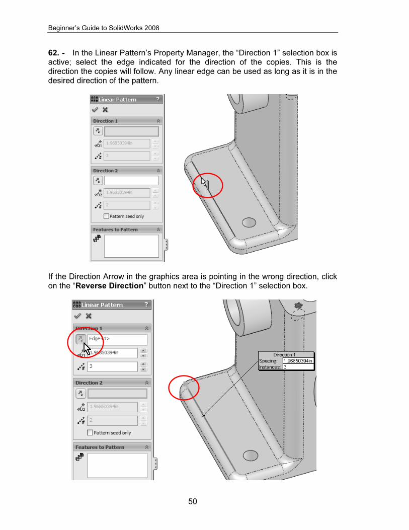
62. - In the Linear Pattern’s Property Manager, the “Direction 1” selection box is active; select the edge indicated for the direction of the copies. This is the direction the copies will follow. Any linear edge can be used as long as it is in the desired direction of the pattern.
If the Direction Arrow in the graphics area is pointing in the wrong direction, click on the “Reverse Direction” button next to the “Direction 1” selection box.

Copyrighted Material
Copyrighted
Material
Copyrighted Material
Copyrighted
Material
Beginner’s Guide to SolidWorks 2008
51
63. - Now click in the “Features to Pattern” selection box to activate it and select the previous cut operation from the fly-out Feature Manager. Change the spacing between the copies to 0.75” and total copies to 3 (this value includes the original). Click OK to finish the command.
64. - To copy the previous linear pattern to the other side of the Housing, select the “Mirror” icon to mirror the Linear Pattern about the “Right Plane” to copy the holes.

Copyrighted Material
Copyrighted
Material
Copyrighted Material
Copyrighted
Material
Beginner’s Guide to SolidWorks 2008
52
65. - Add a 0.125” fillet to the edges indicated to finish the Housing as a finishing touch. Save the finished part as “Housing” and close the file.