Embed Size (px)
Citation preview
2
BEFORE YOU STARTThe T4 is a high-competition, high-quality, 1/10-scale touring car intended for persons aged 16 years and older with previous experience building and operating RC model racing cars. This is not a toy; it is a precision racing model. This model racing car is not intended for use by beginners, inexperienced customers, or by children without direct supervision of a responsible, knowledgeable adult. If you do not fulfill these requirements, please return the kit in unused and unassembled form back to the shop where you have purchased it.
Before building and operating your T4, YOU MUST read through all of the operating instructions and instruction manual and fully understand them to get
the maximum enjoyment and prevent unnecessary damage. Read carefully and fully understand the instructions before beginning assembly.
Make sure you review this entire manual, the included set-up book, and examine all details carefully. If for some reason you decide The T4 is not what you wanted or expected, do not continue any further. Your hobby dealer cannot accept your T4 kit for return or exchange after it has been partially or fully assembled.
Contents of the box may differ from pictures. In line with our policy of continuous product development, the exact specifications of the kit may vary without prior notice.
SAFETY PRECAUTIONSContains:LEAD (CAS 7439-92-1) ANTIMONY (CAS 7440-36-0)WARNING: This product contains a chemical known to the state of California to cause cancer and birth defects or other reproductive harm.CAUTION: CANCER HAZARDContains lead, a listed carcinogen. Lead is harmful if ingested. Wash thoroughly after using. DO NOT use product while eating, drinking or using tobacco products. May cause chronic effects to gastrointestinal tract, CNS, kidneys, and blood. MAY CAUSE BIRTH DEFECTS.
When building, using and/or operating this model always wear protective glasses and gloves.
Take appropriate safety precautions prior to operating this model. You are responsible for this model‘s assembly and safe operation! Please read the instruction manual before building and operating this model and follow all safety precautions. Always keep the instruction manual at hand for quick reference, even after completing the assembly. Use only genuine and original authentic XRAY parts for maximum performance. Using any third party parts on this model will void guaranty immediately.
Improper operation may cause personal and/or property damage. XRAY and its distributors have no control over damage resulting from shipping, improper construction, or improper usage. XRAY assumes and accepts no responsibility for personal and/or property damages resulting from the use of improper building materials, equipment and operations. By purchasing any item produced by XRAY, the buyer expressly warrants that he/she is in compliance with all applicable federal, state and local laws and regulation regarding the purchase, ownership and use of the item. The buyer expressly agrees to indemnify and hold harmless XRAY for all claims resulting directly or indirectly from the purchase, ownership or use of the product. By the act of assembling or operating this product, the user accepts all resulting liability. If the buyer is not prepared to accept this liability, then he/she should return this kit in new, unassembled, and unused condition to the place of purchase.
IMPORTANT NOTES – GENERAL• This product is not suitable for children under 16 years of age without the
direct supervision of a responsible and knowledgeable adult.• Carefully read all manufacturers warnings and cautions for any parts used in
the construction and use of your model.• Assemble this kit only in places away from the reach of very small children.• First-time builders and users should seek advice from people who have
building experience in order to assemble the model correctly and to allow the model to reach its performance potential.
• Exercise care when using tools and sharp instruments.• Take care when building, as some parts may have sharp edges.• Keep small parts out of reach of small children. Children must not be allowed
to put any parts in their mouth, or pull vinyl bag over their head.• Read and follow instructions supplied with paints and/or cement, if used (not
included in kit).• Immediately after using your model, do NOT touch equipment on the
model such as the motor and speed controller, because they generate high temperatures. You may seriously burn yourself seriously touching them.
• Follow the operating instructions for the radio equipment at all times.• Do not put fingers or any objects inside rotating and moving parts, as this
may cause damage or serious injury as your finger, hair, clothes, etc. may get caught.
• Be sure that your operating frequency is clear before turning on or running your model, and never share the same frequency with somebody else at the same time. Ensure that others are aware of the operating frequency you are using and when you are using it.
• Use a transmitter designed for ground use with RC cars. Make sure that no one else is using the same frequency as yours in your operating area. Using the same frequency at the same time, whether it is driving, flying or sailing, can cause loss of control of the RC model, resulting in a serious accident.
• Always turn on your transmitter before you turn on the receiver in the car. Always turn off the receiver before turning your transmitter off.
• Keep the wheels of the model off the ground when checking the operation of the radio equipment.
• Disconnect the battery pack before storing your model.• When learning to operate your model, go to an area that has no obstacles
that can damage your model if your model suffers a collision.• Remove any sand, mud, dirt, grass or water before putting your model away.• If the model behaves strangely, immediately stop the model, check and clear
the problem.• To prevent any serious personal injury and/or damage to property, be
responsible when operating all remote controlled models.• The model car is not intended for use on public places and roads or areas where
its operation can conflict with or disrupt pedestrian or vehicular traffic.• Because the model car is controlled by radio, it is subject to radio interference
from many sources that are beyond your control. Since radio interference can cause momentary loss of control, always allow a safety margin in all directions around the model in order to prevent collisions.
• Do not use your model: - Near real cars, animals, or people that are unaware that an RC car is being
driven. - In places where children and people gather - In residential districts and parks - In limited indoor spaces - In wet conditions - In the street - In areas where loud noises can disturb others, such as hospitals and
residential areas. - At night or anytime your line of sight to the model may be obstructed or
impaired in any way.
To prevent any serious personal injury and/or damage to property, please beresponsible when operating all remote controlled models.
Failure to follow these instructions will be considered as abuse and/or neglect.
CUSTOMER SUPPORT XRAY EuropeK Vystavisku 699291101 TrenčínSlovakia, EUROPEPhone: 421-32-7401100Fax: 421-32-7401109E-mail: [email protected]
We have made every effort to make these instructions as easy to understand as possible. However, if you have any difficulties, problems, or questions, please do not hesitate to contact the XRAY support team at [email protected]. Also, please visit our Web site at www.teamxray.com to find the latest updates, set-up information, option parts, and many other goodies. We pride ourselves on taking excellent care of our customers.
You can join thousands of XRAY fans and enthusiasts in our online community at: www.teamxray.com
XRAY USARCAmerica, 2970 Blystone Lane, Suite 109 Dallas, Texas 75220USAPhone: (800) 519-7221 * (214) 744-2400Fax: (214) 744-2401E-mail: [email protected]
3
IMPORTANT NOTES – ELECTRICAL• Insulate any exposed electrical wiring (using heat shrink tubing or electrical
tape) to prevent dangerous short circuits. Take maximum care in wiring, connecting and insulating cables. Make sure cables are always connected securely. Check connectors for if they become loose. And if so, reconnect them securely. Never use R/C models with damaged wires. A damaged wire is extremely dangerous, and can cause short-circuits resulting in fire. Please have wires repaired at your local hobby shop.
• Low battery power will result in loss of control. Loss of control can occur due to a weak battery in either the transmitter or the receiver. Weak running battery may also result in an out of control car if your car‘s receiver power is supplied by the running battery. Stop operation immediately if the car starts to slow down.
• When not using RC model, always disconnect and remove battery. • Do not disassemble battery or cut battery cables. If the running battery short-
circuits, approximately 300W of electricity can be discharged, leading to fire or burns. Never disassemble battery or cut battery cables.
• Use a recommended charger for the receiver and transmitter batteries and follow the instructions correctly. Over-charging, incorrect charging, or using inferior chargers can cause the batteries to become dangerously hot.
Recharge battery when necessary. Continual recharging may damage battery and, in the worst case, could build up heat leading to fire. If battery becomes extremely hot during recharging, please ask your local hobby shop for check and/or repair and/or replacement.
• Regularly check the charger for potential hazards such as damage to the cable, plug, casing or other defects. Ensure that any damage is rectified before using the charger again. Modifying the charger may cause short-circuit or overcharging leading to a serious accident. Therefore do not modify the charger.
• Always unplug charger when recharging is finished.• Do not recharge battery while battery is still warm. After use, battery retains
heat. Wait until it cools down before charging. • Do not allow any metal part to short circuit the receiver batteries or other
electrical/electronic device on the model.• Immediately stop running if your RC model gets wet as may cause short
circuit. • Please dispose of batteries responsibly. Never put batteries into fire.
WARRANTYXRAY guarantees this model kit to be free from defects in both material and workmanship within 30 days of purchase. The total monetary value under warranty will in no case exceed the cost of the original kit purchased. This warranty does not cover any components damaged by use or modification or as a result of wear. Part or parts missing from this kit must be reported within 30 days of purchase. No part or parts will be sent under warranty without proof of purchase. Should you find a defective or missing part, contact the local distributor. Service and customer support will be provided through local hobby store where you have purchased the kit, therefore make sure to purchase any XRAY products at your local hobby store. This model racing car is considered to be a high-performance racing vehicle. As such this vehicle will be used in an extreme range of conditions and situations, all which may cause premature wear or failure of any component. XRAY has no control over usage of vehicles once they leave the dealer, therefore XRAY can only offer warranty against all manufacturer‘s defects in materials, workmanship, and assembly at point of sale and before use. No warranties are expressed or implied that cover damage caused by what is considered normal use, or cover or imply how long any model cars‘ components or electronic components will last before requiring replacement.
Due to the high performance level of this model car you will need to periodically maintain and replace consumable components. Any and all warranty coverage will not cover replacement of any part or component damaged by neglect, abuse, or improper or unreasonable use. This includes but is not limited to
damage from crashing, chemical and/or water damage, excessive moisture, improper or no maintenance, or user modifications which compromise the integrity of components. Warranty will not cover components that are considered consumable on RC vehicles. XRAY does not pay nor refund shipping on any component sent to XRAY or its distributors for warranty. XRAY reserves the right to make the final determination of the warranty status of any component or part.
Limitations of LiabilityXRAY makes no other warranties expressed or implied. XRAY shall not be liable for any loss, injury or damages, whether direct, indirect, special, incidental, or consequential, arising from the use, misuse, or abuse of this product and/or any product or accessory required to operate this product. In no case shall XRAY‘s liability excess the monetary value of this product.
Take adequate safety precautions prior to operating this model. You are responsible for this model’s assembly and safe operation.
Disregard of the any of the above cautions may lead to accidents, personal injury, or property damage. XRAY MODEL RACING CARS assumes no responsibility for any injury, damage, or misuse of this product during assembly or operation, nor any addictions that may arise from the use of this product.All rights reserved.
QUALITY CERTIFICATE
XRAY MODEL RACING CARS uses only the highest quality materials, the best compounds for molded parts and the most sophisticated manufacturing processes of TQM (Total Quality Management). We guarantee that all parts of a newly-purchased kit are manufactured with the highest regard to quality. However, due to the many factors inherent in model racecar competition, we cannot guarantee
any parts once you start racing the car. Products which have been worn out, abused, neglected or improperly operated will not be covered under warranty. We wish you enjoyment of this high-quality and high-performance RC car and wish you best success on the track!
In line with our policy of continuous product development, the exact specifications of the kit may vary. In the unlikely event of any problems with your new kit, you should contact the model shop where you purchased it, quoting the part number.We do reserve all rights to change any specification without prior notice. All rights reserved.
R/C & BUILDING TIPS
• Make sure all fasteners are properly tightened. Check them periodically.• Make sure that chassis screws do not protrude from the chassis.• For the best performance, it is very important that great care is taken to ensure
the free movement of all parts.• Clean all ball-bearings so they move very easily and freely.• Tap or pre-thread the plastic parts when threading screws.• Self-tapping screws cut threads into the parts when being tightened. Do not use
excessive force when tightening the self-tapping screws because you may strip out the thread in the plastic. We recommended you stop tightening a screw when you feel some resistance.
• Ask your local hobby shop for any advice.
Please support your local hobby shop. We at XRAY Model Racing Cars support all local hobby dealers. Therefore we ask you, if at all possible, to purchase XRAY products at your hobby dealer and give them your support like we do. If you have difficulty finding XRAY products, please check out www.teamxray.com to get advice, or contact us via email at [email protected], or contact the XRAY distributor in your country.
4
NOT INCLUDED
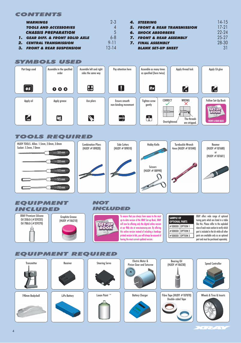
To ensure that you always have access to the most up-to-date version of the XRAY Set-up Book, XRAY will now be offering only the digital online version at our Web site at www.teamxray.com. By offering this online version instead of including a hardcopy printed version in kits, you will always be assured of having the most current updated version.
XRAY offers wide range of optional tuning parts which are listed in a table like this. Please reffer to the exploded view of each main section to verify which part is included in the kit while all other parts are available only as an optional part and must be purchased separately.
SYMBOLS USED
L=R 2xCA
OIL
CORRECT WRONG
OvertightenedThe threads are stripped.
Part bags used Assemble left and right sides the same way
Assemble in the specified order
Pay attention here Assemble as many times as specified (here twice)
Apply CA glue
TOOLS REQUIRED
EQUIPMENT REQUIRED
EQUIPMENTINCLUDED
Apply oil Use pliers
XRAY Premium SiliconeOil 350cSt (#359235)Oil 700cSt (#359270)
Side Cutters(HUDY #189010)
Hobby Knife Turnbuckle Wrench 4mm (HUDY #181040)
Reamer(HUDY #107600)
or(HUDY #107601)
Combination Pliers(HUDY #189020)
HUDY TOOLS: Allen: 1.5mm, 2.0mm, 3.0mmSocket: 5.5mm, 7.0mm
Transmitter Steering ServoReceiver
TL05
Tighten screw gently
Apply thread lock
Lexan Paint ™ Battery Charger Wheels & Tires & Inserts
Apply grease Ensure smooth non-binding movement
2.0 mm
3.0 mm
1.5 mm
7.0 mm
5.5 mm
Graphite Grease(HUDY #106210)
Bearing Oil(HUDY #106230)
Follow Set-Up Book
FRONT & REAR AxLES
Scissors(HUDY #188990)
4.0 mm
SAMPLE OFOPTIONAL PARTS#30XXXX OPTION 1#30XXXX OPTION 2#30XXXX OPTION 3
CONTENTS
Speed Controller
LiPo Battery
Pinion Gear and Setscrew
190mm Bodyshell
Electric Motor &
Fibre Tape (HUDY #107870)Double-sided Tape
WARNINGS 2-3 TOOLS AND ACCESSORIES 4 CHASSIS PREPARATION 5 1. GEAR DIFF. & FRONT SOLID AXLE 6-8 2. CENTRAL TRANSMISSION 9-11 3. FRONT & REAR SUSPENSION 12-14
4. STEERING 14-15 5. FRONT & REAR TRANSMISSION 17-21 6. SHOCK ABSORBERS 22-24 7. FRONT & REAR ASSEMBLY 25-27 7. FINAL ASSEMBLY 28-30 BLANK SET-UP SHEET 31
5
CA
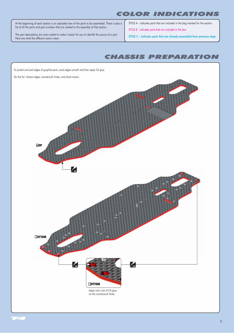
At the beginning of each section is an exploded view of the parts to be assembled. There is also a list of all the parts and part numbers that are related to the assembly of that section.
The part descriptions are color-coded to make it easier for you to identify the source of a part. Here are what the different colors mean:
STYLE A - indicates parts that are included in the bag marked for the section.
STYLE B - indicates parts that are included in the box.
STYLE C - indicates parts that are already assembled from previous steps.
CHASSIS PREPARATION
COLOR INDICATIONS
To protect and seal edges of graphite parts, sand edges smooth and then apply CA glue.
Do this for: chassis edges, countersunk holes, and shock towers.
CA CA
Apply only a bit of CA glue. on the countersunk holes.
6
1. GEAR DIFFERENTIAL & FRONT SOLID AXLE
Use tweezers to insert pin.
981210P 2x10
981210P 2x10
972050O 5x2
972050O 5x2
964050S 5x15x0.3
964050S 5x15x0.3
➊
➋➌
➍➍ ➍
➎
➎
➊
➋
➌
➍
➎
DETAIL ➎STEP
STEP DETAIL
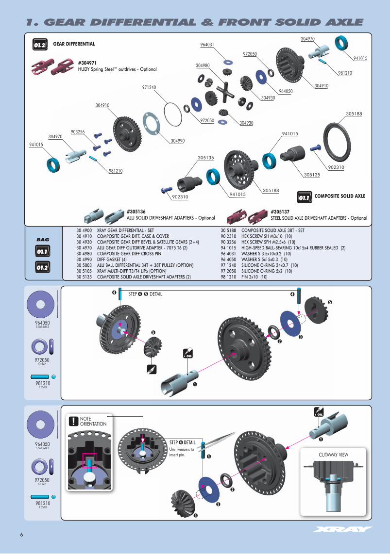
30 4900 XRAY GEAR DIFFERENTIAL - SET30 4910 COMPOSITE GEAR DIFF. CASE & COVER 30 4930 COMPOSITE GEAR DIFF BEVEL & SATELLITE GEARS (2+4) 30 4970 ALU GEAR DIFF OUTDRIVE ADAPTER - 7075 T6 (2)30 4980 COMPOSITE GEAR DIFF CROSS PIN30 4990 DIFF GASKET (4)30 5003 ALU BALL DIFFERENTIAL 34T + 38T PULLEY (OPTION)30 5105 XRAY MULTI-DIFF T3/T4 LiPo (OPTION)30 5135 COMPOSITE SOLID AXLE DRIVESHAFT ADAPTERS (2)
30 5188 COMPOSITE SOLID AXLE 38T - SET90 2310 HEX SCREW SH M3x10 (10)90 3256 HEX SCREW SFH M2.5x6 (10)94 1015 HIGH-SPEED BALL-BEARING 10x15x4 RUBBER SEALED (2)96 4031 WASHER S 3.5x10x0.2 (10)96 4050 WASHER S 5x15x0.3 (10) 97 1240 SILICONE O-RING 24x0.7 (10)97 2050 SILICONE O-RING 5x2 (10) 98 1210 PIN 2x10 (10)
304970
#304971HUDY Spring Steel™ outdrives - Optional
#305136ALU SOLID DRIVESHAFT ADAPTERS - Optional
#305137STEEL SOLID AXLE DRIVESHAFT ADAPTERS - Optional
304910964050
972050
304990
304910
903256
981210
981210
304970
941015
971240
972050
964031
304980
304930
304930
305188
941015
305135
902310
305135
941015305188
902310 COMPOSITE SOLID AXLE
941015
GEAR DIFFERENTIAL
➍
NOTE ORIENTATION
CUTAWAY VIEW
BAG
7
1. GEAR DIFFERENTIAL & FRONT SOLID AXLE1. GEAR DIFFERENTIAL & FRONT SOLID AXLE
964031S 3.5x10x0.2
971240O 24x0.7
903256SFH M2.5x6
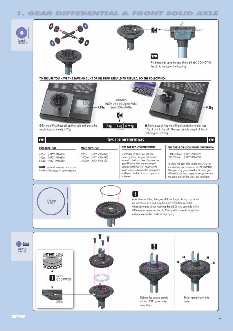
Tighten the screws equally but do NOT tighten them completely.
Finish tightening in this order.
➊
➋
➌
➍
After disassembling the gear diff the large O-ring may have an increased size and may be more difficult to re-install.We recommend either inserting the old O-ring carefully in the diff cover, or replacing the old O-ring with a new O-ring if the old one cannot be made to fit properly.
Fill differential up to the top of the diff pin. DO NOT fill the diff to the top of the housing.
TO ENSuRE YOu hAvE ThE SAME AMOuNT OF OIL FROM REbuILD TO REbuILD, DO ThE FOLLOWING:
➊ Put the diff (without oil) on the scale and check the weight (approximately 7.90g)
➋ Slowly pour oil into the diff and watch the weight. Add 1.3g of oil into the diff. The approximate weight of the diff including oil is 9.20g.
LOW-TRACTION
600cst (HUDY #106360)700cst (HUDY #106370)800cst (HUDY #106380)
NOTE: softer oil increases rear traction, harder oil increases on-power steering.
hIGh-TRACTION
900cst (HUDY #106390)1000cst (HUDY #106410)2000cst (HUDY #106420)
TIPS FOR FRONT DIFFERENTIAL
To increase on-power steering and cornering speed, the gear diff can also be used in the front. Note: If you use the gear diff in the front, we recommend using optional #304971 HUDY Spring Steel™ outdrives because the stress on the outdrives in the front is much higher than in the rear.
uSE ThESE OILS FOR FRONT DIFFERENTIAL
1,000,000 cst (HUDY #106692)500,000 cst (HUDY #106650)
To make the front differential tighter, you can use cleaning gum instead of oil. IMPORTANT! Using cleaning gum instead of oil in the gear differential can lead to gear breakage because the gears are working under dry conditions.
TIPS FOR DIFFERENTIALS
7.9g + 1.3g = 9.2g
7.90g 9.20g
#107865HUDY Ultimate Digital Pocket
Scale 300g±0.01g
DETAIL
DETAIL
NOTEORIENTATION
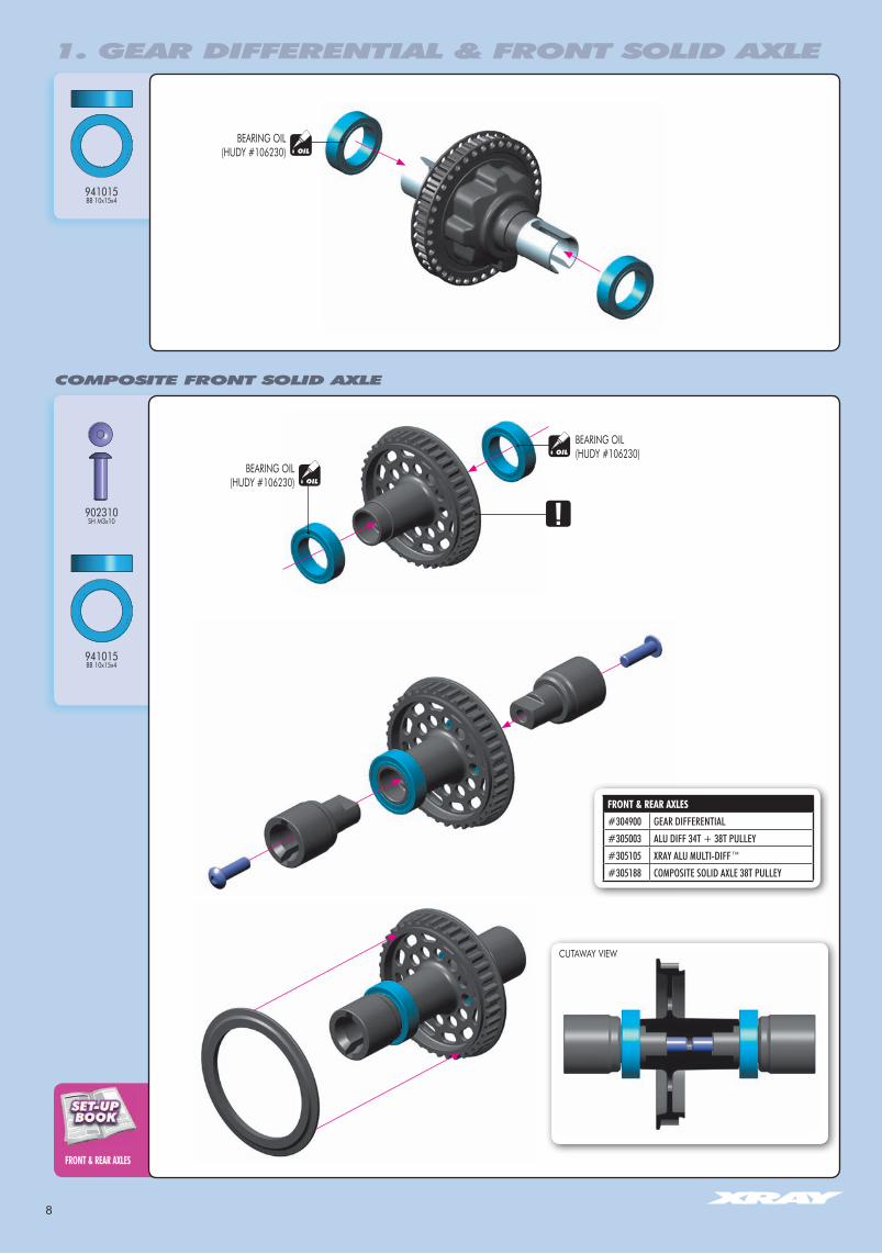
8
COMPOSITE FRONT SOLID AXLE
FRONT & REAR AxLES
1. GEAR DIFFERENTIAL & FRONT SOLID AXLE
902310SH M3x10
941015BB 10x15x4
941015BB 10x15x4
OIL
OIL
OIL
BEARING OIL(HUDY #106230)
BEARING OIL(HUDY #106230)
FRONT & REAR AxLES#304900 GEAR DIFFERENTIAL#305003 ALU DIFF 34T + 38T PULLEY#305105 XRAY ALU MULTI-DIFF™#305188 COMPOSITE SOLID AXLE 38T PULLEY
BEARING OIL(HUDY #106230)
CUTAWAY VIEW
9
305188
940510
965050
304900
903306
903310
903306
303053-O
302030-O
303054-O
303054-O
902306
902306
305577
303086
981212
960030
305784940510
301134
903306
902310
902306
305446
305432
303028-O
302030-O
302030-O
303028-O
302085
302062
305521-K
902304
902306
302062
305577
965050
302030-O
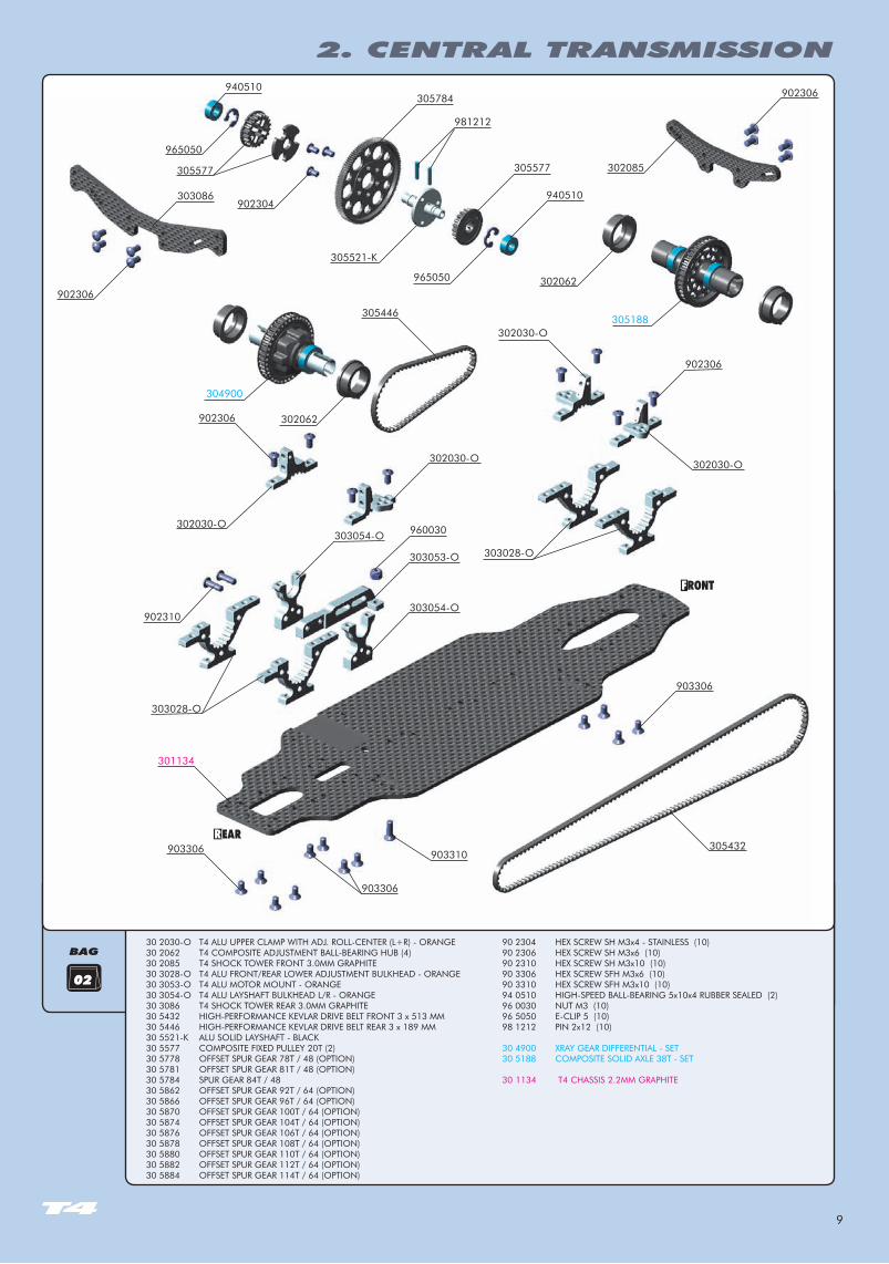
2. CENTRAL TRANSMISSION
BAG
02
30 2030-O T4 ALU UPPER CLAMP WITH ADJ. ROLL-CENTER (L+R) - ORANGE30 2062 T4 COMPOSITE ADJUSTMENT BALL-BEARING HUB (4)30 2085 T4 SHOCK TOWER FRONT 3.0MM GRAPHITE30 3028-O T4 ALU FRONT/REAR LOWER ADJUSTMENT BULKHEAD - ORANGE30 3053-O T4 ALU MOTOR MOUNT - ORANGE30 3054-O T4 ALU LAYSHAFT BULKHEAD L/R - ORANGE30 3086 T4 SHOCK TOWER REAR 3.0MM GRAPHITE30 5432 HIGH-PERFORMANCE KEVLAR DRIVE BELT FRONT 3 x 513 MM30 5446 HIGH-PERFORMANCE KEVLAR DRIVE BELT REAR 3 x 189 MM30 5521-K ALU SOLID LAYSHAFT - BLACK30 5577 COMPOSITE FIXED PULLEY 20T (2)30 5778 OFFSET SPUR GEAR 78T / 48 (OPTION)30 5781 OFFSET SPUR GEAR 81T / 48 (OPTION)30 5784 SPUR GEAR 84T / 4830 5862 OFFSET SPUR GEAR 92T / 64 (OPTION)30 5866 OFFSET SPUR GEAR 96T / 64 (OPTION)30 5870 OFFSET SPUR GEAR 100T / 64 (OPTION)30 5874 OFFSET SPUR GEAR 104T / 64 (OPTION)30 5876 OFFSET SPUR GEAR 106T / 64 (OPTION)30 5878 OFFSET SPUR GEAR 108T / 64 (OPTION)30 5880 OFFSET SPUR GEAR 110T / 64 (OPTION)30 5882 OFFSET SPUR GEAR 112T / 64 (OPTION)30 5884 OFFSET SPUR GEAR 114T / 64 (OPTION)
90 2304 HEX SCREW SH M3x4 - STAINLESS (10)90 2306 HEX SCREW SH M3x6 (10)90 2310 HEX SCREW SH M3x10 (10)90 3306 HEX SCREW SFH M3x6 (10)90 3310 HEX SCREW SFH M3x10 (10)94 0510 HIGH-SPEED BALL-BEARING 5x10x4 RUBBER SEALED (2)96 0030 NUT M3 (10)96 5050 E-CLIP 5 (10)98 1212 PIN 2x12 (10) 30 4900 XRAY GEAR DIFFERENTIAL - SET30 5188 COMPOSITE SOLID AXLE 38T - SET
30 1134 T4 CHASSIS 2.2MM GRAPHITE

10
gEARINg ADJuSTMENT
902304SH M3x4
965050C5
981212P 2x12
940510BB 5x10x4
SPuR gEARS 48P#305778 OFFSET SPUR GEAR 78T / 48P#305781 OFFSET SPUR GEAR 81T / 48P#305784 SPUR GEAR 84T / 48P
SPuR gEARS 64P#305862 OFFSET SPUR GEAR 92T / 64P#305866 OFFSET SPUR GEAR 96T / 64P#305870 OFFSET SPUR GEAR 100T / 64P#305874 OFFSET SPUR GEAR 104T / 64P#305876 OFFSET SPUR GEAR 106T / 64P#305878 OFFSET SPUR GEAR 108T / 64P#305880 OFFSET SPUR GEAR 110T / 64P#305882 OFFSET SPUR GEAR 112T / 64P#305884 OFFSET SPUR GEAR 114T / 64P
903306SFH M3x6
902310SH M3x10
960030N M3x10
903310SFH M3x10
NOTE ORIENTATIONOnly when using XRAY OFFSET spur gears.
NOTEORIENTATION
NOTE ORIENTATION
Short belt Long belt
BEARING OIL(HUDY #106230)
OIL
OIL
BEARING OIL(HUDY #106230)
2. CENTRAL TRANSMISSION
CUTAWAY VIEW
1. 2. 3.
3x6mm
Tighten screws in order indicated.
M3 Nut must always be tightened fully. When tightening the nut, use either pliers or 5.5mm socket tool.
IMPORTANT!
Do not tighten fully.
3x6mm
Tighten fully all 3x6mm screws.
Tighten fully all 3x6mm screws.
3x10mm
Do not tighten fully.
11
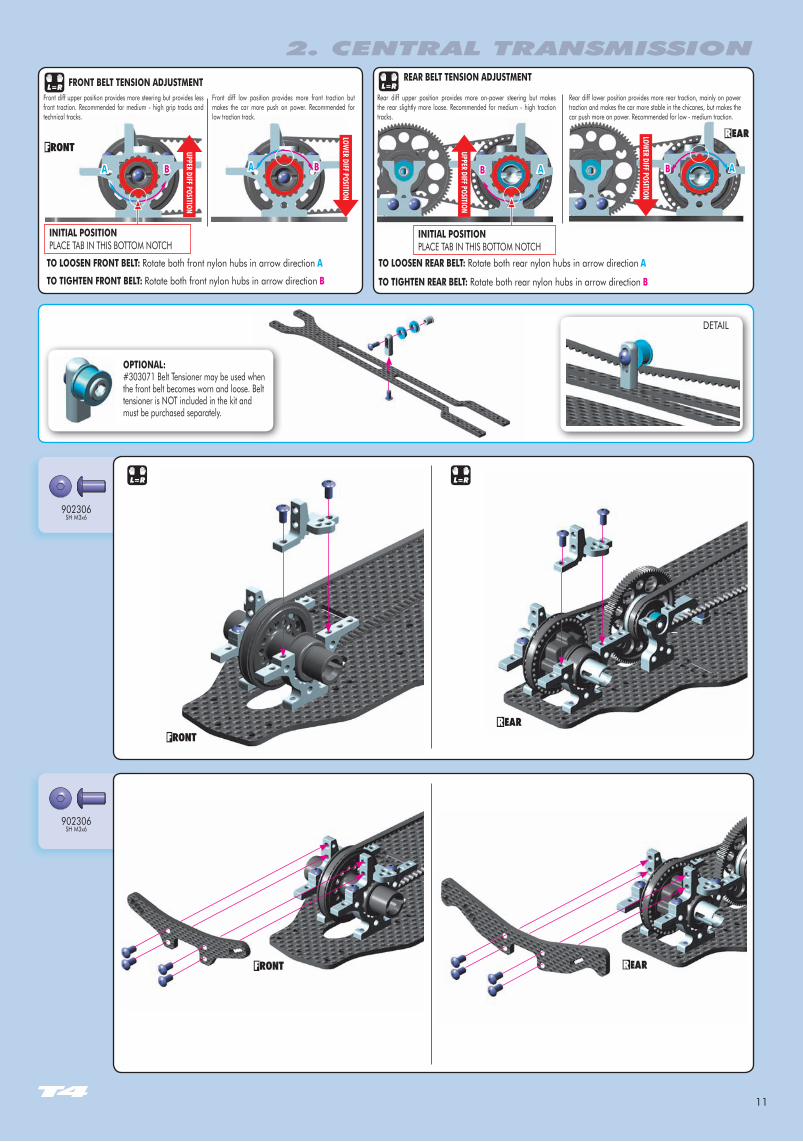
902306SH M3x6
902306SH M3x6
OPTIONAL:#303071 Belt Tensioner may be used when the front belt becomes worn and loose. Belt tensioner is NOT included in the kit and must be purchased separately.
DETAIL
TO TIGhTEN FRONT bELT: Rotate both front nylon hubs in arrow direction b
FRONT bELT TENSION ADJuSTMENT
A b
TO LOOSEN REAR bELT: Rotate both rear nylon hubs in arrow direction A
REAR bELT TENSION ADJuSTMENT
b A
L=R L=R
L=R L=R
A b Ab
TO LOOSEN FRONT bELT: Rotate both front nylon hubs in arrow direction A
TO TIGhTEN REAR bELT: Rotate both rear nylon hubs in arrow direction b
LOwER DIFF POSITION
uPPER DIFF POSITION
LOwER DIFF POSITION
uPPER DIFF POSITION
Front diff low position provides more front traction but makes the car more push on power. Recommended for low traction track.
Front diff upper position provides more steering but provides less front traction. Recommended for medium - high grip tracks and technical tracks.
Rear diff lower position provides more rear traction, mainly on power traction and makes the car more stable in the chicanes, but makes the car push more on power. Recommended for low - medium traction.
Rear diff upper position provides more on-power steering but makes the rear slightly more loose. Recommended for medium - high traction tracks.
INITIAL POSITIONPLACE TAB IN THIS BOTTOM NOTCH
INITIAL POSITIONPLACE TAB IN THIS BOTTOM NOTCH
2. CENTRAL TRANSMISSION
12
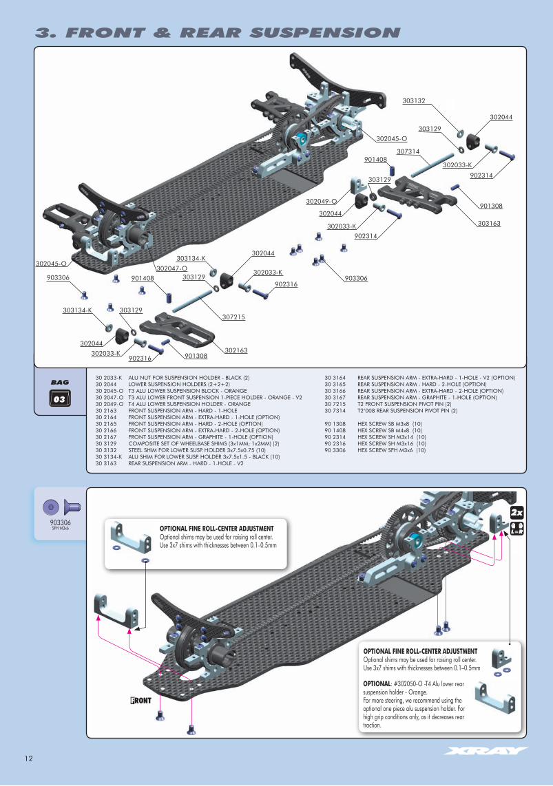
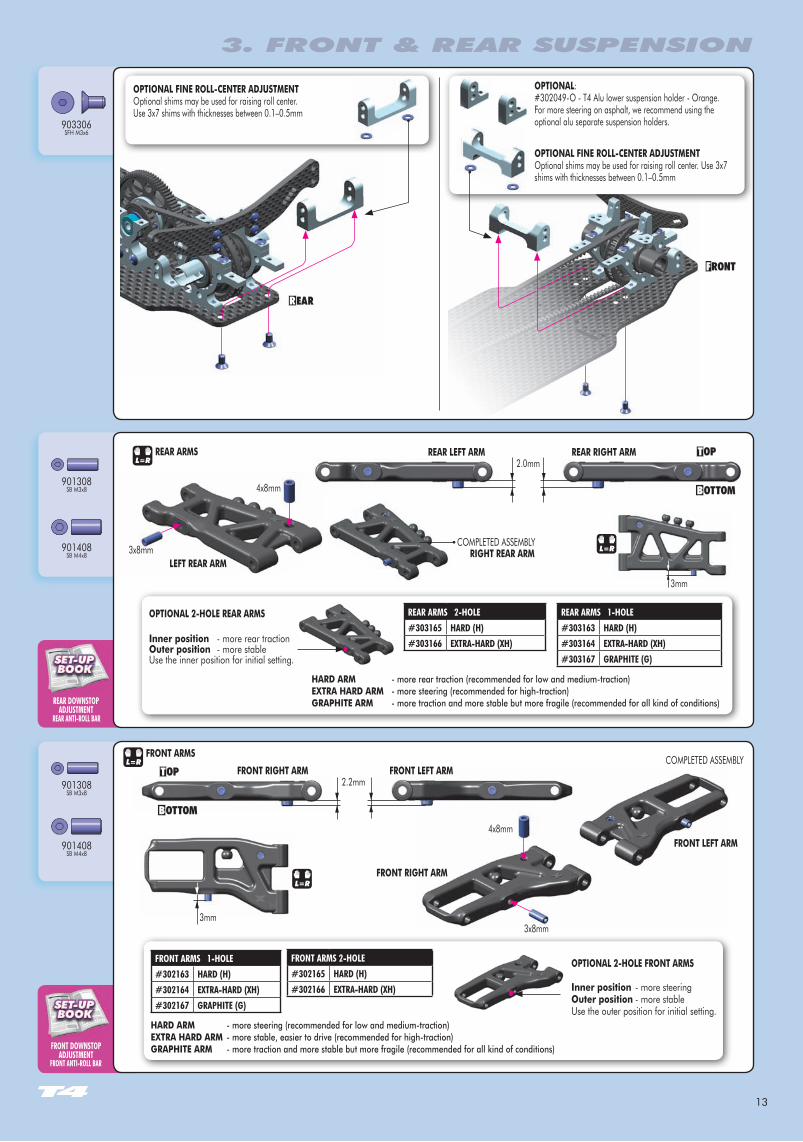
903306SFH M3x6
OPTIONAL: #302050-O -T4 Alu lower rear suspension holder - Orange.For more steering, we recommend using the optional one piece alu suspension holder. For high grip conditions only, as it decreases rear traction.
2x
2x
OPTIONAL FINE ROLL-CENTER ADJuSTMENTOptional shims may be used for raising roll center. Use 3x7 shims with thicknesses between 0.1–0.5mm
OPTIONAL FINE ROLL-CENTER ADJuSTMENTOptional shims may be used for raising roll center. Use 3x7 shims with thicknesses between 0.1–0.5mm
3. FRONT & REAR SUSPENSION
BAG
03
30 2033-K ALU NUT FOR SUSPENSION HOLDER - BLACK (2)30 2044 LOWER SUSPENSION HOLDERS (2+2+2)30 2045-O T3 ALU LOWER SUSPENSION BLOCK - ORANGE30 2047-O T3 ALU LOWER FRONT SUSPENSION 1-PIECE HOLDER - ORANGE - V230 2049-O T4 ALU LOWER SUSPENSION HOLDER - ORANGE30 2163 FRONT SUSPENSION ARM - HARD - 1-HOLE30 2164 FRONT SUSPENSION ARM - EXTRA-HARD - 1-HOLE (OPTION)30 2165 FRONT SUSPENSION ARM - HARD - 2-HOLE (OPTION)30 2166 FRONT SUSPENSION ARM - EXTRA-HARD - 2-HOLE (OPTION)30 2167 FRONT SUSPENSION ARM - GRAPHITE - 1-HOLE (OPTION)30 3129 COMPOSITE SET OF WHEELBASE SHIMS (3x1MM; 1x2MM) (2)30 3132 STEEL SHIM FOR LOWER SUSP. HOLDER 3x7.5x0.75 (10)30 3134-K ALU SHIM FOR LOWER SUSP. HOLDER 3x7.5x1.5 - BLACK (10)30 3163 REAR SUSPENSION ARM - HARD - 1-HOLE - V2
30 3164 REAR SUSPENSION ARM - EXTRA-HARD - 1-HOLE - V2 (OPTION)30 3165 REAR SUSPENSION ARM - HARD - 2-HOLE (OPTION)30 3166 REAR SUSPENSION ARM - EXTRA-HARD - 2-HOLE (OPTION)30 3167 REAR SUSPENSION ARM - GRAPHITE - 1-HOLE (OPTION)30 7215 T2 FRONT SUSPENSION PIVOT PIN (2)30 7314 T2‘008 REAR SUSPENSION PIVOT PIN (2)
90 1308 HEX SCREW SB M3x8 (10)90 1408 HEX SCREW SB M4x8 (10)90 2314 HEX SCREW SH M3x14 (10)90 2316 HEX SCREW SH M3x16 (10)90 3306 HEX SCREW SFH M3x6 (10)
302044
303129
302033-K
902316
302044
302045-O
303129901408903306
303134-K
303134-K
303129
307314901408
303129
303132
307215
302163
302047-O
901308
901308
303163302044
903306
902316302033-K
302044
302045-O
302033-K
302049-O
902314
302033-K
902314
13
FRONT DOwNSTOPADJuSTMENT
FRONT ANTI-ROLL BAR
REAR DOwNSTOPADJuSTMENT
REAR ANTI-ROLL BAR
901308SB M3x8
901408SB M4x8
901308SB M3x8
901408SB M4x8
REAR ARMS 1-HOLE#303163 HARD (H)#303164 ExTRA-HARD (xH)#303167 gRAPHITE (g)
FRONT ARMS 1-HOLE#302163 HARD (H)#302164 ExTRA-HARD (xH)#302167 gRAPHITE (g)
REAR ARMS 2-HOLE#303165 HARD (H)#303166 ExTRA-HARD (xH)
FRONT ARMS 2-HOLE#302165 HARD (H)#302166 ExTRA-HARD (xH)
903306SFH M3x6
REAR LEFT ARM REAR RIGhT ARM
RIGhT REAR ARM
FRONT LEFT ARMFRONT RIGhT ARM
LEFT REAR ARM
REAR ARMS
3. FRONT & REAR SUSPENSION
3mm
2.0mm
3mm
4x8mm
3x8mm
L=R
FRONT RIGhT ARM
FRONT LEFT ARM
L=R
COMPLETED ASSEMBLY3x8mm
4x8mm
COMPLETED ASSEMBLYFRONT ARMS
L=R
2.2mm
L=R
Inner position - more rear tractionOuter position - more stableUse the inner position for initial setting.
OPTIONAL 2-hOLE REAR ARMS
hARD ARM - more rear traction (recommended for low and medium-traction)EXTRA hARD ARM - more steering (recommended for high-traction)GRAPhITE ARM - more traction and more stable but more fragile (recommended for all kind of conditions)
hARD ARM - more steering (recommended for low and medium-traction)EXTRA hARD ARM - more stable, easier to drive (recommended for high-traction)GRAPhITE ARM - more traction and more stable but more fragile (recommended for all kind of conditions)
OPTIONAL 2-hOLE FRONT ARMS
Inner position - more steeringOuter position - more stableUse the outer position for initial setting.
OPTIONAL FINE ROLL-CENTER ADJuSTMENTOptional shims may be used for raising roll center. Use 3x7 shims with thicknesses between 0.1–0.5mm
OPTIONAL: #302049-O - T4 Alu lower suspension holder - Orange.For more steering on asphalt, we recommend using the optional alu separate suspension holders.
OPTIONAL FINE ROLL-CENTER ADJuSTMENTOptional shims may be used for raising roll center. Use 3x7 shims with thicknesses between 0.1–0.5mm
14
TOE-IN ADJuSTMENTTRACK-wIDTH ADJuSTMENTwHEELBASE ADJuSTMENT
ROLL CENTER ADJuSTMENTSQuAT ADJuSTMENT
TOE-IN ADJuSTMENTTRACK-wIDTH ADJuSTMENTwHEELBASE ADJuSTMENT
ROLL CENTER ADJuSTMENTSQuAT ADJuSTMENT
TOE-IN ADJuSTMENTTRACK-wIDTH ADJuSTMENTwHEELBASE ADJuSTMENT
ROLL CENTER ADJuSTMENTSQuAT ADJuSTMENT
DETAIL
0mm
3. FRONT & REAR SUSPENSION
DETAIL
0mm
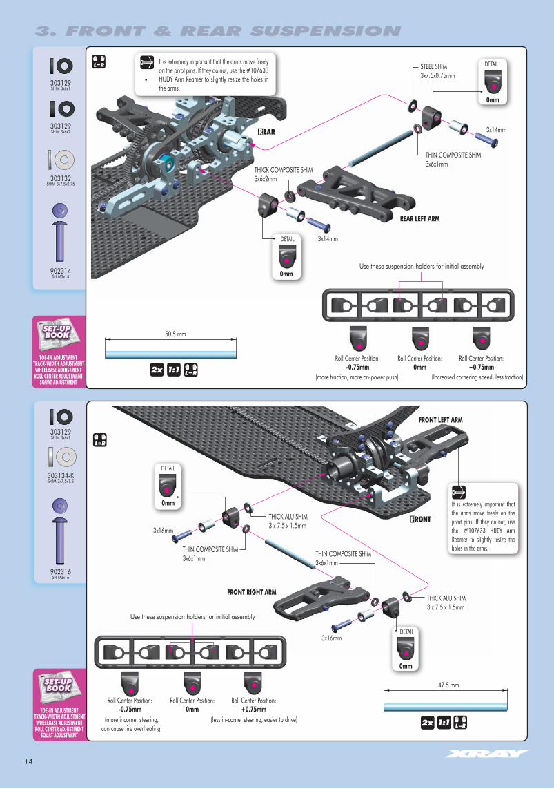
47.5 mm
3x16mm
L=R2x
3x16mm
L=R
Roll Center Position: -0.75mm
Roll Center Position:0mm
Roll Center Position: +0.75mm
FRONT LEFT ARM
FRONT RIGhT ARM
902316SH M3x16
303134-KSHIM 3x7.5x1.5
303129SHIM 3x6x1
THIN COMPOSITE SHIM3x6x1mm
THICK ALU SHIM3 x 7.5 x 1.5mm
THICK ALU SHIM3 x 7.5 x 1.5mm
THIN COMPOSITE SHIM3x6x1mm
It is extremely important that the arms move freely on the pivot pins. If they do not, use the #107633 HUDY Arm Reamer to slightly resize the holes in the arms.
Use these suspension holders for initial assembly
50.5 mm
THIN COMPOSITE SHIM3x6x1mm
3x14mm
3x14mm
2x 1:1
1:1
L=R
REAR LEFT ARM
Roll Center Position: -0.75mm
(more traction, more on-power push)
(more incorner steering,can cause tire overheating)
(less in-corner steering, easier to drive)
(Increased cornering speed, less traction)
Roll Center Position:0mm
Roll Center Position: +0.75mm
Use these suspension holders for initial assembly
303129SHIM 3x6x1
303129SHIM 3x6x2
902314SH M3x14
STEEL SHIM3x7.5x0.75mm
303132SHIM 3x7.5x0.75
THICK COMPOSITE SHIM3x6x2mm
It is extremely important that the arms move freely on the pivot pins. If they do not, use the #107633 HUDY Arm Reamer to slightly resize the holes in the arms.
DETAIL
DETAIL
0mm
0mm
15
FRONT TOE-IN ADJuSTMENT
BAG
2x L=R
OIL
3x1mm & 1x2mm composite shims
303129SHIM 3x6x1
940508BB 5x8
930306BB 3x6
903308SFH M3x8
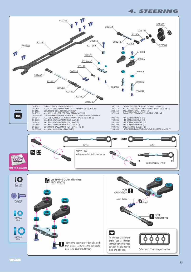
approximately 47mm
Use BEARING OIL for all bearings
NOTEORIENTATION
6mm thread3x6x1
NOTEORIENTATION
Tighten the screws gently but fully, and then loosen 1/3 turn so the composite dual servo saver moves freely.
SERVO LINKAdjust servo link to fit your servo
65.4mm 65.4mm
To change Ackermann angle, use 2 identical shims (of same thickness) between the alu steering plate and ball end.
(HUDY #106230)
4. STEERING
04
902306902305
940508
302526
940508
302535
903306
301195
902306
302654
303129
930306
302546-O
303128-K
303129
302653
372503
372503
303454
302655
903308
302663
302612
302663
302663
302612
302663
303212
30 1195 T4 UPPER DECK 2.0MM GRAPHITE30 2525 ALU DUAL SERVO SAVER ARM + BALL-BEARINGS (2) (OPTION)30 2526 COMPOSITE DUAL SERVO SAVER ARM30 2535 ALU STEERING POST FOR DUAL SERVO SAVER (2)30 2546-O T4 ALU STEERING PLATE 8MM FOR DUAL SERVO SAVER - ORANGE30 2612 ALU ADJ. TURNBUCKLE M3 L/R 39 MM - SWISS 7075 T6 (2)30 2653 BALL END 4.9MM WITH THREAD 6MM (2)30 2654 BALL END 4.9MM WITH THREAD 8MM (2)30 2655 BALL END 4.9MM WITH THREAD 10MM (2) 30 2663 COMPOSITE BALL JOINT 5 MM - OPEN - V2 (8)30 3128-K ALU SHIM 3x6x6.0MM - BLACK (10)
30 3129 COMPOSITE SET OF SHIMS (3x1MM; 1x2MM) (2)30 3212 ALU ADJ. TURNBUCKLE L/R 26 MM - SWISS 7075 T6 (2)30 3454 BALL JOINT 4.9MM - OPEN (4)37 2503 COMPOSITE SERVO SAVER - X-STIFF - SET - V2
90 2305 HEX SCREW SH M3x5 (10)90 2306 HEX SCREW SH M3x6 (10)90 3306 HEX SCREW SFH M3x6 (10)90 3308 HEX SCREW SFH M3x8 (10)93 0306 BALL-BEARING 3x6x2.5 (2)94 0508 HIGH-SPEED BALL-BEARING 5x8x2.5 RUBBER SEALED (2)
16
ACKERMANN ADJuSTMENTSTEERINg THROw SYMMETRY
CHASSIS FLEx SETTINgTOP DECK FLEx SETTINg
902305SH M3x5
902306SH M3x6
303129SHIM 3x6x2
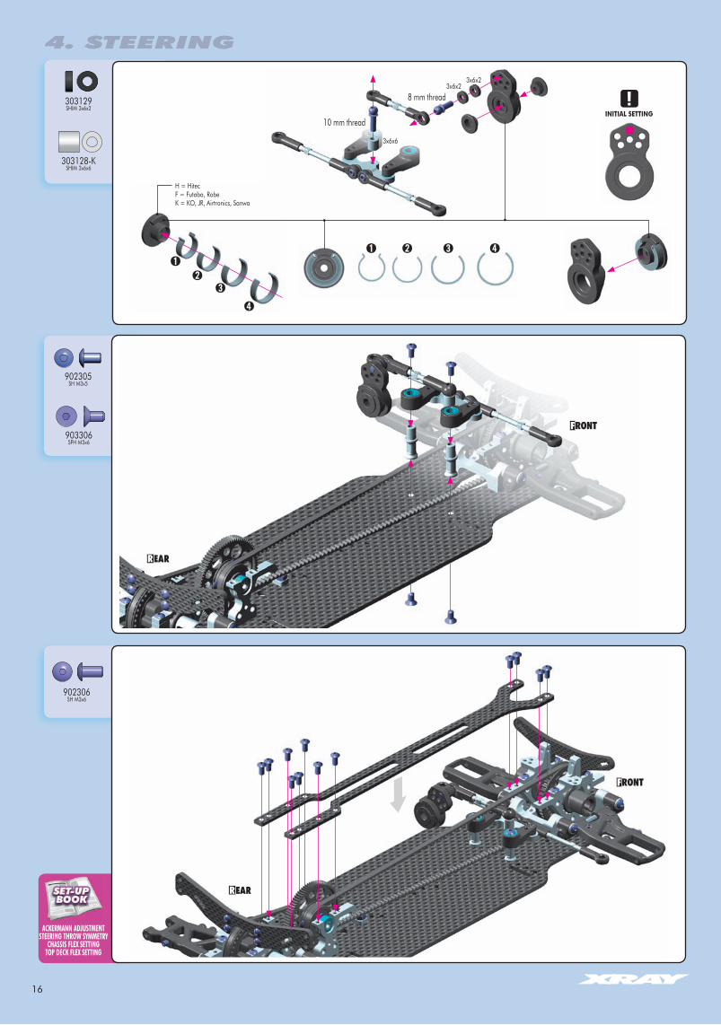
303128-KSHIM 3x6x6
H = HitecF = Futaba, RobeK = KO, JR, Airtronics, Sanwa
903306SFH M3x6
INITIAL SETTING
3x6x2
3x6x6
3x6x2
8 mm thread
10 mm thread
4. STEERING
17
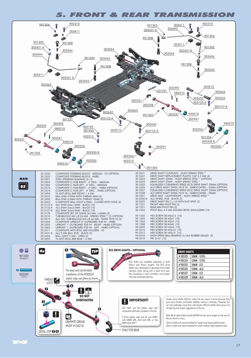
901302SB M3x2.5
305392P 2x10
DRIVE SHAFTS#305323 50MM - STEEL#305324 52MM - STEEL#305325 50MM - ECS#305326 52MM - ALU#305327 52MM - ECS#305328 50MM - ALU
05
4x
THREAD LOCK
GRAPHITE GREASE(HUDY #106210)
ONLY FOR REARDETAIL STEP
TL
TIP
For easy and comfortable installation of the #305241 plastic caps use pliers as shown.
DO NOT OvERTIGhTEN Longer drive shafts (52mm) make the car easier to drive because they
give more traction and better stability, mainly in chicanes. However, the car will understeer more than with shorter (50mm) shafts which give a lot of steering and impart aggression to the car.
Both left & right shafts should ALWAYS be the same length at one end of the car (front or rear).
52mm shafts are recommended for carpet and large asphalt tracks.50mm shafts are recommended for small-medium tight asphalt tracks.
DO NOT use the plastic caps with composite solid axle included in the kits.
3.5mm plastic caps are for use ONLY with GEAR diffs, ALU ball diffs, or the XRAY Multi-Diff™.
ECS shafts are available optionally in both 50mm and 52mm lengths. The ECS drive shafts were developed to decrease front wheel vibration when racing with a solid front axle, thus providing a much smoother and quieter ride and increased steering.
ECS DRIvE ShAFTS - OPTIONAL
IMPORTANT!
BAG
5. FRONT & REAR TRANSMISSION
30 2252 COMPOSITE STEERING BLOCK - MEDIUM - V2 (OPTION)30 2253 COMPOSITE STEERING BLOCK - HARD30 2291 STEEL STEERING BUSHING (2+2)30 2363 COMPOSITE C-HUB RIGHT - 4° DEG. - MEDIUM30 2364 COMPOSITE C-HUB LEFT - 4° DEG. - MEDIUM30 2373 COMPOSITE C-HUB RIGHT - 4° DEG. - HARD (OPTION)30 2374 COMPOSITE C-HUB LEFT - 4° DEG. - HARD (OPTION)30 2494 T4 ANTI-ROLL BAR FRONT 1.4 MM30 2652 BALL END 4.9MM WITH THREAD 4MM (2)30 2655 BALL END 4.9MM WITH THREAD 10MM (2)30 2665 COMPOSITE BALL JOINT 4.9MM - CLOSED WITH HOLE (4)30 3122-K ALU SHIM 3x6x1.0MM - BLACK (10)30 3123-K ALU SHIM 3x6x2.0MM - BLACK (10) 30 3127-K ALU SHIM 3x6x4.0MM - BLACK (10) 30 3129 COMPOSITE SET OF SHIMS (3x1MM; 1x2MM) (2)30 3210 TURNBUCKLE M3 L/R 26 MM - SPRING STEEL™ (2) (OPTION)30 3212 ALU ADJ. TURNBUCKLE M3 L/R 26 MM - SWISS 7075 T6 (2)30 3354 COMPOSITE UPRIGHT 0° OUTBOARD TOE-IN - HARD30 3353 UPRIGHT 1° OUTBOARD TOE-IN - RIGHT - HARD (OPTION)30 3363 UPRIGHT 1° OUTBOARD TOE-IN - LEFT - HARD (OPTION)30 3411 COMPOSITE ANTI-ROLL BAR HOLDERS - V230 3431-K ALU 5 MM BALL END - BLACK (2)30 3454 BALL JOINT 5 MM - OPEN (4)30 3492 T4 ANTI-ROLL BAR REAR 1.2 MM
30 5231 DRIVE SHAFT COUPLING - HUDY SPRING STEEL™30 5241 DRIVE SHAFT REPLACEMENT PLASTIC CAP 3.5 MM (4)30 5323 DRIVE SHAFT 50MM - HUDY SPRING STEEL™ (OPTION)30 5324 DRIVE SHAFT 52MM - HUDY SPRING STEEL™30 5325 EQUALIZED CORNERING SPEED (ECS) DRIVE SHAFT 50MM (OPTION)30 5326 ALU DRIVE SHAFT SWISS 7075 T6 - HARDCOATED - 52MM (OPTION)30 5327 EQUALIZED CORNERING SPEED (ECS) DRIVE SHAFT 52MM (OPTION)30 5328 ALU DRIVE SHAFT SWISS 7075 T6 - HARDCOATED - 50MM30 5341 DRIVE AXLE - LIGHTWEIGHT - HUDY SPRING STEEL™30 5350-K ALU WHEEL HUB - BLACK (2)30 5392 DRIVE SHAFT PIN 2 x 10 WITH FLAT SPOT (2)30 7221 FRONT ARM PIVOT PIN (2)30 7321 REAR ARM PIVOT PIN (2)30 7455 PIVOT BALL 4.9 MM DOUBLE BEVEL SHOULDERS (10)
90 1302 HEX SCREW SB M3x2.5 (10)90 1303 HEX SCREW SB M3x3 (10)90 1304 HEX SCREW SB M3x4 (10)90 1308 HEX SCREW SB M3x8 (10)90 2205 HEX SCREW SH M2x5 (10)90 2310 HEX SCREW SH M3x10 (10)90 2312 HEX SCREW SH M3x12 (10)94 0510 HIGH-SPEED BALL-BEARING 5x10x4 RUBBER SEALED (2)98 0210 PIN 2x10 (10)
902310
305324
902205
901304
303411
901303
901303
303431-K
303431-K
302494
303411
303454
303454
901308
901308
901308
303454
303454
305341
305341
940510
940510
980210
305392
980210
305392
902312
303129307455
307221
901302
901302
305231
305231
302291
901304
302652303123-K
902310
302655
303212
902205
305350-K
302655
302665
940510
302665
303212307321
302652
303454
901308
303454
303431-K
303123-K
303431-K
901303
901303303492
303354
303411 902310
901304
303411
901304
940510
303127-K
305241
305350-K
305328
303122-K
302253
303354
302364
302363
18
CASTER ADJuSTMENT
REAR TOE-IN ADJuSTMENT
CAMBER ADJuSTMENT
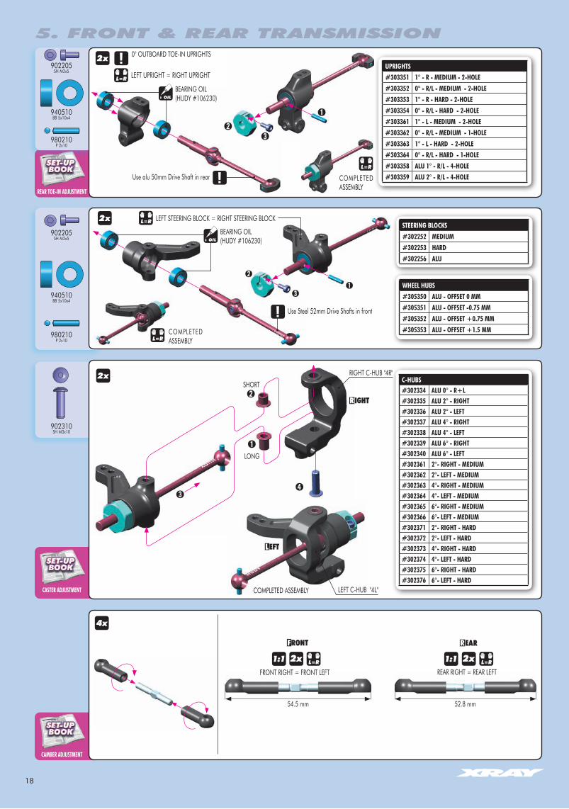
902205SH M2x5
940510BB 5x10x4
980210P 2x10
902205SH M2x5
940510BB 5x10x4
980210P 2x10
902310SH M3x10
wHEEL HuBS#305350 ALu - OFFSET 0 MM#305351 ALu - OFFSET -0.75 MM#305352 ALu - OFFSET +0.75 MM#305353 ALu - OFFSET +1.5 MM
54.5 mm 52.8 mm
0° OUTBOARD TOE-IN UPRIGHTSuPRIgHTS#303351 1° - R - MEDIuM - 2-HOLE#303352 0° - R/L - MEDIuM - 2-HOLE#303353 1° - R - HARD - 2-HOLE#303354 0° - R/L - HARD - 2-HOLE#303361 1° - L - MEDIuM - 2-HOLE#303362 0° - R/L - MEDIuM - 1-HOLE#303363 1° - L - HARD - 2-HOLE#303364 0° - R/L - HARD - 1-HOLE#303358 ALu 1° - R/L - 4-HOLE#303359 ALu 2° - R/L - 4-HOLE
STEERINg BLOCKS#302252 MEDIuM#302253 HARD#302256 ALu
C-HuBS#302334 ALu 0° - R+L#302335 ALu 2° - RIgHT#302336 ALu 2° - LEFT#302337 ALu 4° - RIgHT#302338 ALu 4° - LEFT#302339 ALu 6° - RIgHT#302340 ALu 6° - LEFT#302361 2°- RIgHT - MEDIuM#302362 2°- LEFT - MEDIuM#302363 4°- RIgHT - MEDIuM#302364 4°- LEFT - MEDIuM#302365 6°- RIgHT - MEDIuM#302366 6°- LEFT - MEDIuM#302371 2°- RIgHT - HARD#302372 2°- LEFT - HARD#302373 4°- RIgHT - HARD#302374 4°- LEFT - HARD#302375 6°- RIgHT - HARD#302376 6°- LEFT - HARD
BEARING OIL(HUDY #106230)
L=R L=R
Use alu 50mm Drive Shaft in rear
Use Steel 52mm Drive Shafts in front
OIL
BEARING OIL(HUDY #106230)
OIL
1:1 1:1
5. FRONT & REAR TRANSMISSION
2x
COMPLETED ASSEMBLY
LEFT STEERING BLOCK = RIGHT STEERING BLOCK2x
L=R
2x
COMPLETED ASSEMBLY
FRONT RIGHT = FRONT LEFT REAR RIGHT = REAR LEFT
4x
L=R
RIGHT C-HUB "4R"
LEFT C-HUB "4L"
4x
SHORT
LONG
LEFT UPRIGHT = RIGHT UPRIGHTL=R
COMPLETED ASSEMBLY
L=R
2x 2x
19
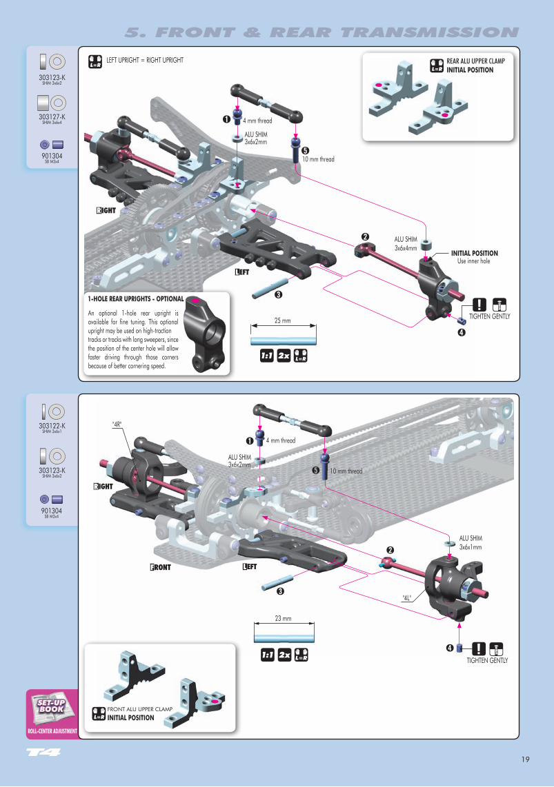
ROLL-CENTER ADJuSTMENT
901304SB M3x4
901304SB M3x4
303123-KSHIM 3x6x2
303123-KSHIM 3x6x2
303127-KSHIM 3x6x4
303122-KSHIM 3x6x1
ALU SHIM3x6x2mm
LEFT UPRIGHT = RIGHT UPRIGHTL=R
4 mm thread
10 mm thread
ALU SHIM3x6x1mm
ALU SHIM3x6x2mm
4 mm thread
10 mm thread
"4L"
"4R"
TIGHTEN GENTLY1:1
23 mm
2x
L=RREAR ALU UPPER CLAMP
FRONT ALU UPPER CLAMPL=R
5. FRONT & REAR TRANSMISSION
TIGHTEN GENTLY
ALU SHIM 3x6x4mm
INITIAL POSITIONUse inner hole
1-hOLE REAR uPRIGhTS - OPTIONAL
An optional 1-hole rear upright is available for fine tuning. This optional upright may be used on high-tractiontracks or tracks with long sweepers, since the position of the center hole will allow faster driving through those corners because of better cornering speed.
INITIAL POSITION
1:1
25 mm
2x L=R
INITIAL POSITION

20
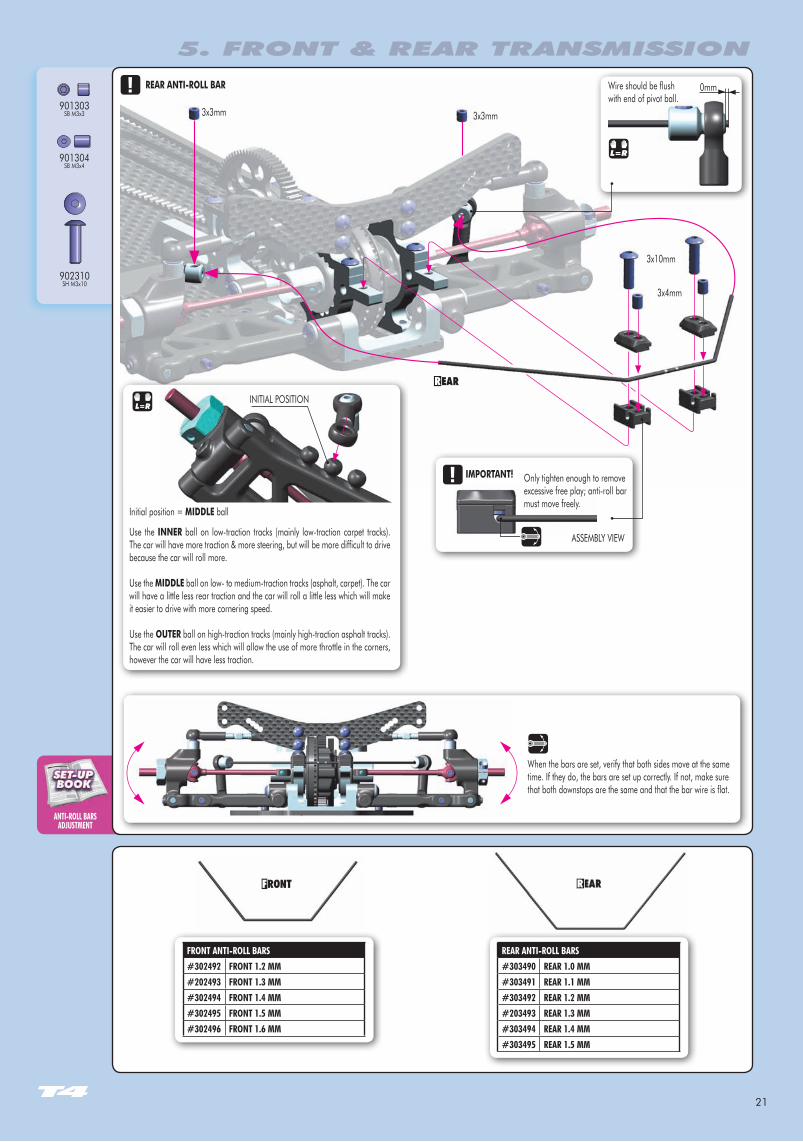
ANTI-ROLL BARSADJuSTMENT
901308SB M3x8
2x 2x1:1
901303SB M3x3
901304SB M3x4
902310SH M3x10
307455PB 5mm
902312SH M3x12
ACKERMANN ADJuSTMENT
RECOMMENDED buMPSTEER SETTINGS:
Carpet - 1mm thick shimAsphalt - 4mm thick shims (longer screw must be used)
The number of shims changes the angles of the steering linkage. When no shims are used, the car is easy to drive into the corner. As the number of shims is increased, in-corner steering increases but the car becomes more difficult to drive.
INITIAL POSITION
L=R
SHIM3x6x1mm
5. FRONT & REAR TRANSMISSION
1.5mm
28mm 27mm
3x3mm
3x3mm
3x4mm
When the bars are set, verify that both sides move at the same time. If they do, the bars are set up correctly. If not, make sure that both downstops are the same and that the bar wire is flat.
3x4mm
IMPORTANT!
ASSEMBLY VIEW
Only tighten enough to remove excessive free play; anti-roll bar must move freely.
Wire should be flush with end of pivot ball.
0mm
3x10mm
3x10mm
FREE MOVEMENT FREE MOVEMENT
L=R
303129SHIM 3x6x1
21
ANTI-ROLL BARSADJuSTMENT
901303SB M3x3
901304SB M3x4
902310SH M3x10
REAR ANTI-ROLL bAR
5. FRONT & REAR TRANSMISSION
3x4mm
3x3mm 3x3mm
When the bars are set, verify that both sides move at the same time. If they do, the bars are set up correctly. If not, make sure that both downstops are the same and that the bar wire is flat.
REAR ANTI-ROLL BARS#303490 REAR 1.0 MM#303491 REAR 1.1 MM#303492 REAR 1.2 MM#203493 REAR 1.3 MM#303494 REAR 1.4 MM#303495 REAR 1.5 MM
L=R
Initial position = MIDDLE ball
Use the INNER ball on low-traction tracks (mainly low-traction carpet tracks). The car will have more traction & more steering, but will be more difficult to drive because the car will roll more.
Use the MIDDLE ball on low- to medium-traction tracks (asphalt, carpet). The car will have a little less rear traction and the car will roll a little less which will make it easier to drive with more cornering speed.
Use the OuTER ball on high-traction tracks (mainly high-traction asphalt tracks). The car will roll even less which will allow the use of more throttle in the corners, however the car will have less traction.
INITIAL POSITION
FRONT ANTI-ROLL BARS#302492 FRONT 1.2 MM#202493 FRONT 1.3 MM#302494 FRONT 1.4 MM#302495 FRONT 1.5 MM#302496 FRONT 1.6 MM
3x10mm
IMPORTANT!
ASSEMBLY VIEW
Only tighten enough to remove excessive free play; anti-roll bar must move freely.
Wire should be flush with end of pivot ball.
0mm
22
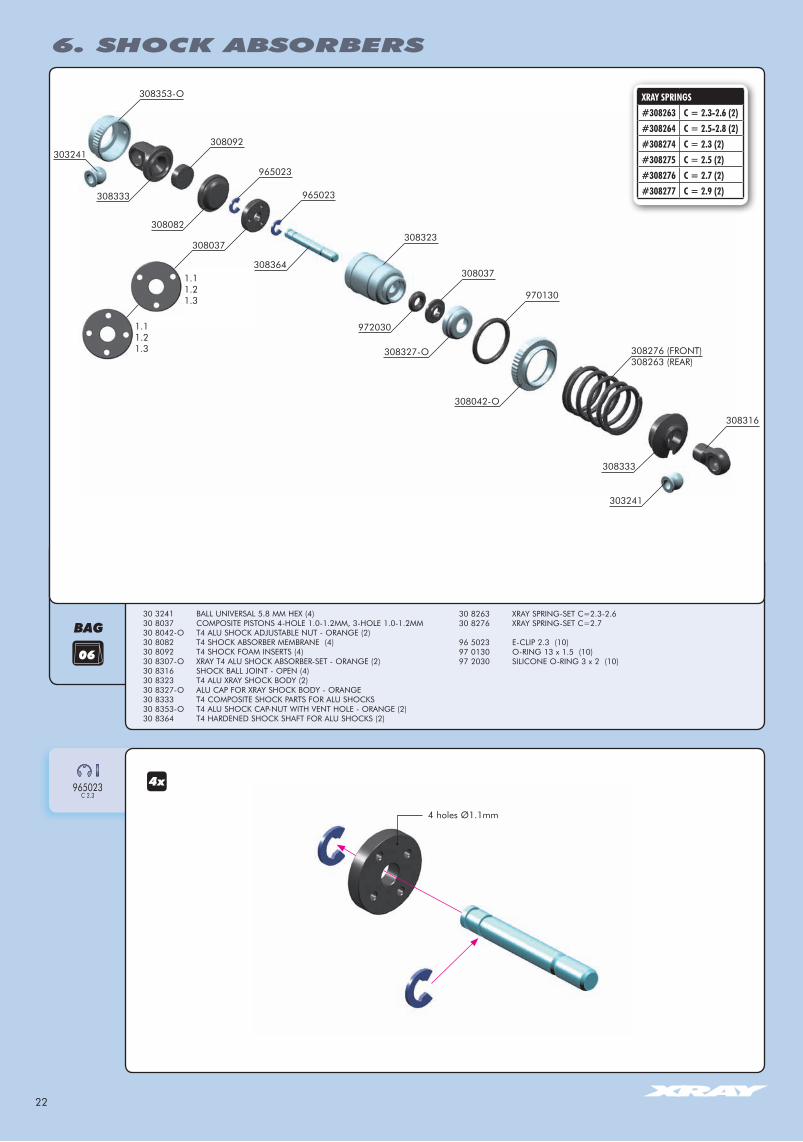
30 3241 BALL UNIVERSAL 5.8 MM HEX (4)30 8037 COMPOSITE PISTONS 4-HOLE 1.0-1.2MM, 3-HOLE 1.0-1.2MM30 8042-O T4 ALU SHOCK ADJUSTABLE NUT - ORANGE (2)30 8082 T4 SHOCK ABSORBER MEMBRANE (4)30 8092 T4 SHOCK FOAM INSERTS (4)30 8307-O XRAY T4 ALU SHOCK ABSORBER-SET - ORANGE (2)30 8316 SHOCK BALL JOINT - OPEN (4)30 8323 T4 ALU XRAY SHOCK BODY (2)30 8327-O ALU CAP FOR XRAY SHOCK BODY - ORANGE30 8333 T4 COMPOSITE SHOCK PARTS FOR ALU SHOCKS30 8353-O T4 ALU SHOCK CAP-NUT WITH VENT HOLE - ORANGE (2)30 8364 T4 HARDENED SHOCK SHAFT FOR ALU SHOCKS (2)
BAG
965023C 2.3
30 8263 XRAY SPRING-SET C=2.3-2.630 8276 XRAY SPRING-SET C=2.7
96 5023 E-CLIP 2.3 (10) 97 0130 O-RING 13 x 1.5 (10)97 2030 SILICONE O-RING 3 x 2 (10)
xRAY SPRINgS#308263 C = 2.3-2.6 (2)#308264 C = 2.5-2.8 (2)#308274 C = 2.3 (2)#308275 C = 2.5 (2)#308276 C = 2.7 (2)#308277 C = 2.9 (2)
1.11.21.3
1.11.21.3
308333
303241
303241
308353-O
308092
308082
308037308323
970130
972030
308037
308042-O
308327-O
308316
308333
965023
965023
308364
308276 (FRONT)308263 (REAR)
4 holes Ø1.1mm
6. SHOCK ABSORBERS
23
SHOCK DAMPINg
EFFECTS OF SHOCK DAMPINg
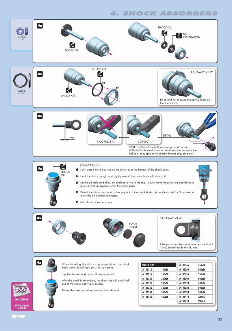
SHOCK OILS#106310 100cSt#106315 150cSt#106320 200cSt#106325 250cSt#106330 300cSt#106335 350cSt#106340 400cSt
#106345 450cSt#106350 500cSt#106355 550cSt#106360 600cSt#106370 700cSt#106380 800cSt#106390 900cSt#106410 1000cSt#106420 2000cSt
970130O 13x1.5
972030O 3x2
1mm
HINT: Pre-thread the ball joint using an M3 screw. WARNING! Be careful not to pre-thread too far, since the ball joint may split or the plastic threads may strip out.
INCORRECT
DETAIL
Fully extend the piston rod so the piston is at the bottom of the shock body.
Hold the shock upright and slightly overfill the shock body with shock oil.
Let the oil settle and allow air bubbles to rise to the top. Slowly move the piston up and down to allow oil into all cavities within the shock body.
Extend the piston rod most of the way out of the shock body. Let the shock rest for 5 minutes to allow the air bubbles to escape.
Add shock oil as necessary.
➊
➋
➌
➍
➎
SHOCK OIL
SHOCK OIL
When installing the shock cap assembly on the shock body, some oil will leak out... this is normal.
Tighten the cap and clean off any excess oil.
After the shock is assembled, the shock rod will push itself out of the shock body fairly quickly.
Follow the next procedure to adjust the rebound.
SHOCK FILLING
CORRECT
SHOCK OIL
➊
➋
SHOCK OIL
NOTEORIENTATION
After you insert the membrane, ensure that it is fully seated inside the alu cap.
CUTAWAY VIEW
FOAM INSERT
SHOCK OIL
SHOCK OIL
CUTAWAY VIEW
Be careful not to cross-thread the collar on the shock body.
6. SHOCK ABSORBERS
24
TECH TIP ➊
➋
➌
➍
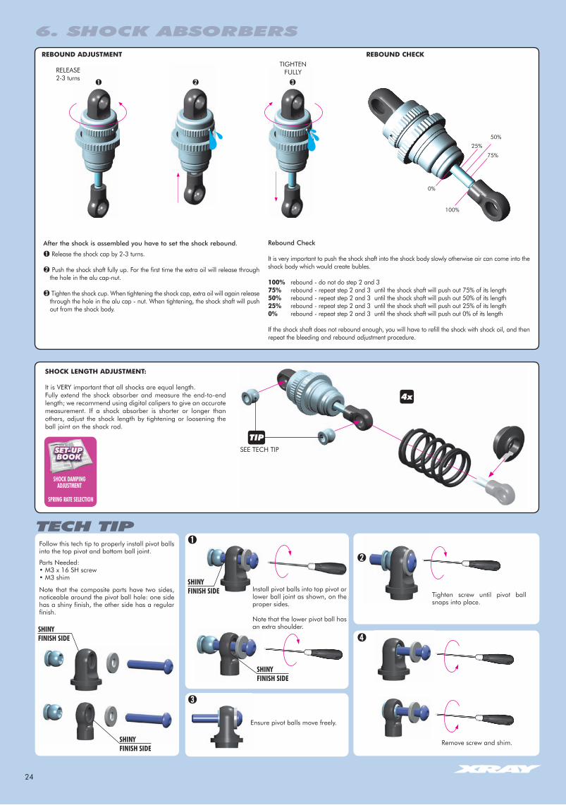
Follow this tech tip to properly install pivot balls into the top pivot and bottom ball joint.
Parts Needed:• M3 x 16 SH screw• M3 shim
Note that the composite parts have two sides, noticeable around the pivot ball hole: one side has a shiny finish, the other side has a regular finish.
Install pivot balls into top pivot or lower ball joint as shown, on the proper sides.
Note that the lower pivot ball has an extra shoulder.
Remove screw and shim.
SHINYFINISH SIDE
Ensure pivot balls move freely.
SHINYFINISH SIDE Tighten screw until pivot ball
snaps into place.
SHINYFINISH SIDE
SHINYFINISH SIDE
SHOCK DAMPINg ADJuSTMENT
SPRINg RATE SELECTION
RELEASE2-3 turns
TIGHTENFULLY
0%
50%
75%
REbOuND ADJuSTMENT REbOuND ChECK
➊ ➋ ➌
100%
25%
After the shock is assembled you have to set the shock rebound.
➊ Release the shock cap by 2-3 turns.
➋ Push the shock shaft fully up. For the first time the extra oil will release through the hole in the alu cap-nut.
➌ Tighten the shock cup. When tightening the shock cap, extra oil will again release through the hole in the alu cap - nut. When tightening, the shock shaft will push out from the shock body.
ShOCK LENGTh ADJuSTMENT:
It is VERY important that all shocks are equal length.Fully extend the shock absorber and measure the end-to-end length; we recommend using digital calipers to give an accurate measurement. If a shock absorber is shorter or longer than others, adjust the shock length by tightening or loosening the ball joint on the shock rod.
Rebound Check
It is very important to push the shock shaft into the shock body slowly otherwise air can come into the shock body which would create bubles.
100% rebound - do not do step 2 and 375% rebound - repeat step 2 and 3 until the shock shaft will push out 75% of its length 50% rebound - repeat step 2 and 3 until the shock shaft will push out 50% of its length25% rebound - repeat step 2 and 3 until the shock shaft will push out 25% of its length0% rebound - repeat step 2 and 3 until the shock shaft will push out 0% of its length
If the shock shaft does not rebound enough, you will have to refill the shock with shock oil, and then repeat the bleeding and rebound adjustment procedure.
SEE TECH TIP
6. SHOCK ABSORBERS
25
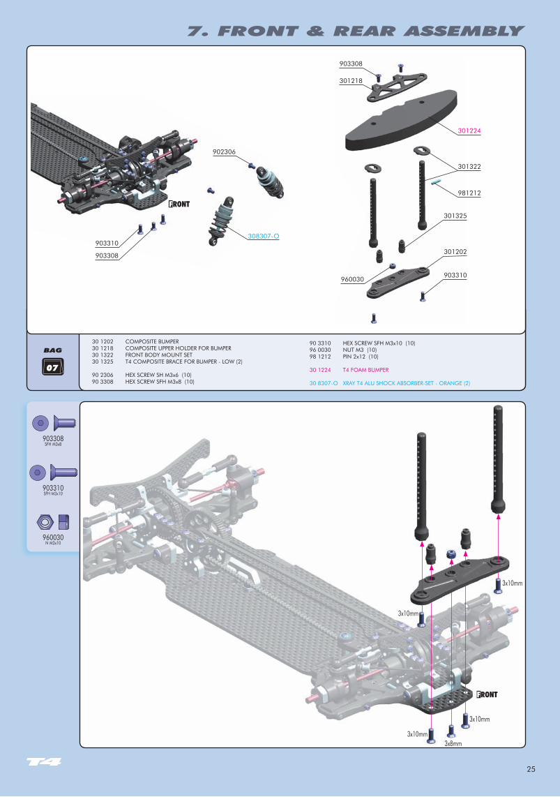
BAG30 1202 COMPOSITE BUMPER30 1218 COMPOSITE UPPER HOLDER FOR BUMPER30 1322 FRONT BODY MOUNT SET30 1325 T4 COMPOSITE BRACE FOR BUMPER - LOW (2) 90 2306 HEX SCREW SH M3x6 (10)90 3308 HEX SCREW SFH M3x8 (10)
90 3310 HEX SCREW SFH M3x10 (10)96 0030 NUT M3 (10)98 1212 PIN 2x12 (10) 30 1224 T4 FOAM BUMPER 30 8307-O XRAY T4 ALU SHOCK ABSORBER-SET - ORANGE (2)
07
903308SFH M3x8
903310SFH M3x10
960030N M3x10
903310
902306
903310301202
301325
981212
301322
301224
903308
301218
308307-O
960030
903308
3x10mm
3x10mm3x8mm
3x10mm
3x10mm
7. FRONT & REAR ASSEMBLY
26
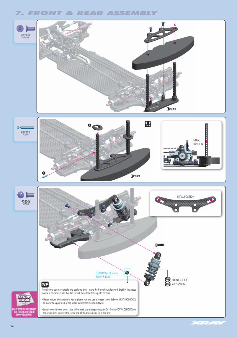
SHOCK POSITION ADJuSTMENTRIDE HEIgHT ADJuSTMENT
DROOP ADJuSTMENT
903308SFH M3x8
981212P 2x12
902306SH M3x6
L=R
FRONT SHOCKC2.7 SPRING
INITIAL POSITION
To make the car more stable and easier to drive, move the front shocks forward. Stability increases mainly in chicanes. Note that the car will have less steering into corners.
• Upper mount (shock tower): Add a plastic nut and use a longer screw 3x8mm (NOT INCLUDED) to move the upper end of the shock away from the shock tower.
• Lower mount (lower arm): Add shims and use a longer setscrew 3x10mm (NOT INCLUDED) on the lower arms to move the lower end of the shock away from the arm.
7. FRONT & REAR ASSEMBLY
L=R
INITIAL POSITION
308019 Set of ShockShims & Nuts
27
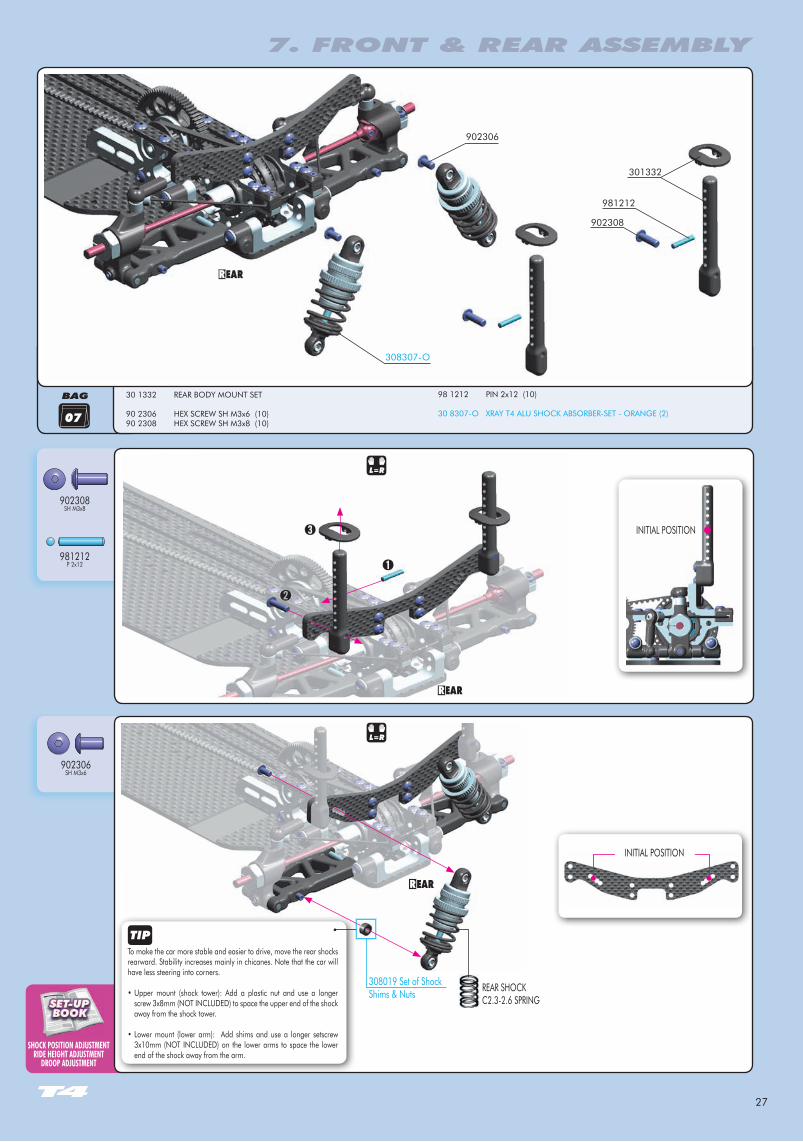
SHOCK POSITION ADJuSTMENTRIDE HEIgHT ADJuSTMENT
DROOP ADJuSTMENT
BAG
07
902306SH M3x6
981212P 2x12
902308SH M3x8
L=R
308307-O
902308
902306
981212
301332
To make the car more stable and easier to drive, move the rear shocks rearward. Stability increases mainly in chicanes. Note that the car will have less steering into corners.
• Upper mount (shock tower): Add a plastic nut and use a longer screw 3x8mm (NOT INCLUDED) to space the upper end of the shock away from the shock tower.
• Lower mount (lower arm): Add shims and use a longer setscrew 3x10mm (NOT INCLUDED) on the lower arms to space the lower end of the shock away from the arm.
30 1332 REAR BODY MOUNT SET 90 2306 HEX SCREW SH M3x6 (10)90 2308 HEX SCREW SH M3x8 (10)
98 1212 PIN 2x12 (10) 30 8307-O XRAY T4 ALU SHOCK ABSORBER-SET - ORANGE (2)
REAR SHOCKC2.3-2.6 SPRING
L=R
7. FRONT & REAR ASSEMBLY
INITIAL POSITION
308019 Set of ShockShims & Nuts
INITIAL POSITION
28
BAG
902308SH M3x8
903306SFH M3x6
306219SHIM 3x6x1
306219SHIM 3x6x2
306219SHIM 3x6x3
07
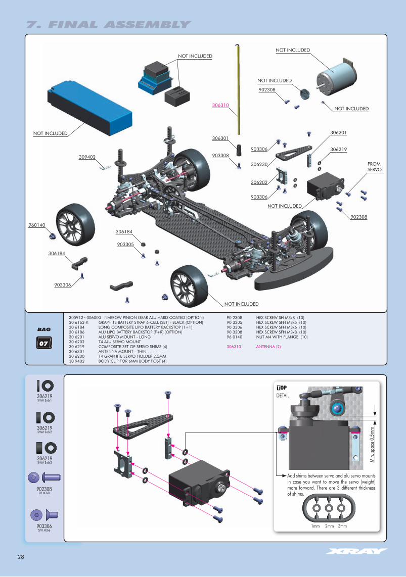
Add shims between servo and alu servo mounts in case you want to move the servo (weight) more forward. There are 3 different thickness of shims.
1mm 2mm 3mm
Min
. spa
ce 0
.5m
m
DETAIL
FROM SERVO
NOT INCLUDED
NOT INCLUDED
NOT INCLUDED
NOT INCLUDED
NOT INCLUDED
NOT INCLUDED
NOT INCLUDED
306219
306201
903306
903306
306202
306230
902308
902308
306310
306301
903308309402
960140
306184
306184
903305
903306
305912~306000 NARROW PINION GEAR ALU HARD COATED (OPTION)30 6163-K GRAPHITE BATTERY STRAP 6-CELL (SET) - BLACK (OPTION)30 6184 LONG COMPOSITE LIPO BATTERY BACKSTOP (1+1)30 6186 ALU LIPO BATTERY BACKSTOP (F+R) (OPTION)30 6201 ALU SERVO MOUNT - LONG30 6202 T4 ALU SERVO MOUNT30 6219 COMPOSITE SET OF SERVO SHIMS (4)30 6301 ANTENNA MOUNT - THIN30 6230 T4 GRAPHITE SERVO HOLDER 2.5MM 30 9402 BODY CLIP FOR 6MM BODY POST (4)
90 2308 HEX SCREW SH M3x8 (10)90 3305 HEX SCREW SFH M3x5 (10)90 3306 HEX SCREW SFH M3x6 (10)90 3308 HEX SCREW SFH M3x8 (10)96 0140 NUT M4 WITH FLANGE (10)
306310 ANTENNA (2)
7. FINAL ASSEMBLY
29
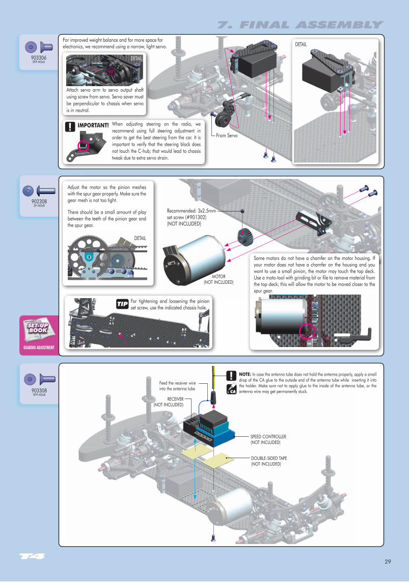
gEARINg ADJuSTMENT
902308SH M3x8
903308SFH M3x8
903306SFH M3x6
For improved weight balance and for more space for electronics, we recommend using a narrow, light servo.
DOUBLE-SIDED TAPE (NOT INCLUDED)
RECEIVER (NOT INCLUDED)
SPEED CONTROLLER (NOT INCLUDED)
Feed the receiver wire into the antenna tube
NOTE: In case the antenna tube does not hold the antenna properly, apply a small drop of the CA glue to the outside end of the antenna tube while inserting it into the holder. Make sure not to apply glue to the inside of the antenna tube, or the antenna wire may get permanently stuck.
MOTOR (NOT INCLUDED)
Adjust the motor so the pinion meshes with the spur gear properly. Make sure the gear mesh is not too tight.
There should be a small amount of play between the teeth of the pinion gear and the spur gear.
Recommended: 3x2.5mm set screw (#901302)(NOT INCLUDED)
DETAIL
DETAIL
7. FINAL ASSEMBLY
For tightening and loosening the pinion set screw, use the indicated chassis hole.
Some motors do not have a chamfer on the motor housing. If your motor does not have a chamfer on the housing and you want to use a small pinion, the motor may touch the top deck. Use a moto-tool with grinding bit or file to remove material from the top-deck; this will allow the motor to be moved closer to the spur gear.
DETAIL
Attach servo arm to servo output shaft using screw from servo. Servo saver must be perpendicular to chassis when servo is in neutral.
When adjusting steering on the radio, we recommend using full steering adjustment in order to get the best steering from the car. It is important to verify that the steering block does not touch the C-hub; that would lead to chassis tweak due to extra servo strain.
IMPORTANT!
90°
CA
From Servo
30
RIDE HEIgHT ADJuSTMENTDROOP ADJuSTMENT
960140N M4
DETAIL
903306SFH M3x6
903305SFH M3x5
7. FINAL ASSEMBLY
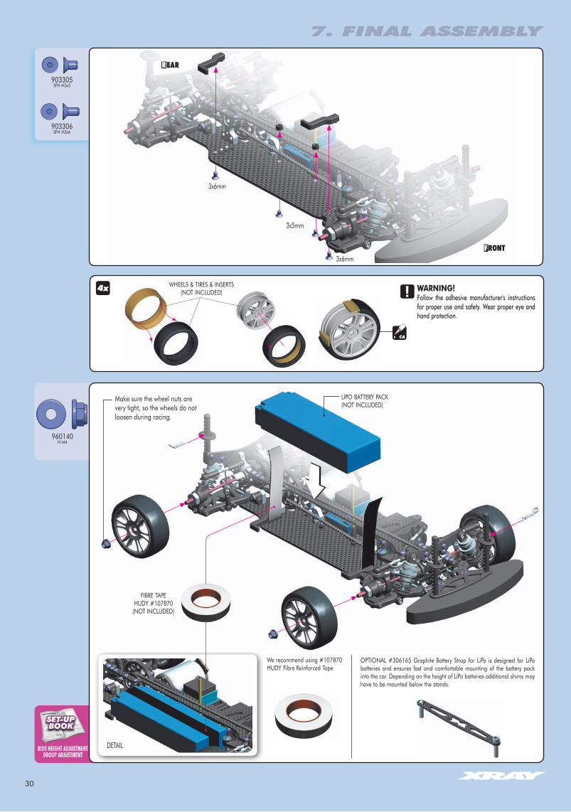
WARNING!Follow the adhesive manufacturer's instructions for proper use and safety. Wear proper eye and hand protection.
CA
Make sure the wheel nuts are very tight, so the wheels do not loosen during racing.
FIBRE TAPEHUDY #107870(NOT INCLUDED)
LIPO BATTERY PACK(NOT INCLUDED)
WHEELS & TIRES & INSERTS (NOT INCLUDED)4x
OPTIONAL #306165 Graphite Battery Strap for LiPo is designed for LiPo batteries and ensures fast and comfortable mounting of the battery pack into the car. Depending on the height of LiPo batteries additional shims may have to be mounted below the stands.
We recommend using #107870 HUDY Fibre Reinforced Tape
3x5mm
3x6mm
3x6mm
31
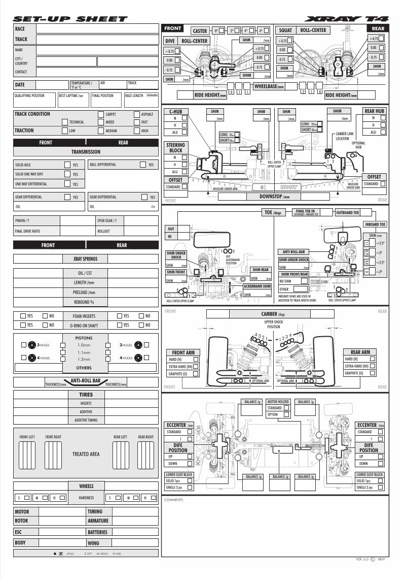
PINION / T SPUR GEAR / T
FINAL DRIVE RATIO ROLLOUT
RACE
TRACK
NAME
CITY /COUNTRY
CONTACT
ONE WAY DIFFERENTIAL
YES
SOLID ONE WAY DIFF.
BALL DIFFERENTIALSOLID AXLE
YES
YES
YES
TRANSMISSION
REARFRONT
TRACK CONDITION
TRACTION
TECHNICAL MIXED
ASPHALTCARPET
FAST
LOW MEDIUM HIGH
ESC BATTERIES
BODY WING
INSERTS
TIRES
ADDITIVE
ADDITIVE TIMING
QUALIFYING POSITION BEST LAPTIME /sec FINAL POSITION /minutesRACE LENGTH
TEMPERATURE /°F or °CDATE AIR TRACK
REARFRONT
XRAY SPRINGS
LENGTH /mm
PRELOAD /mm
REBOUND %
OIL / CST
YES NO YES NO
YES NO YES NO
FOAM INSERTS
O-RING ON SHAFT
THICKNESS/mm THICKNESS/mmANTI-ROLL BAR
MOTOR
ROTOR
TIMING
ARMATURE
1.0mmHOLES
OTHERS
PISTONS
1.2mm
1.1mmHOLES4
3 HOLES
HOLES4
3
HARDNESS
WHEELS
S M HS M H
SET-UP SHEET
DIFF.POSITION
DOWN
UP
1
STANDARD
ECCENTER /mm
DIFF.POSITION
DOWN
UP
1
STANDARD
ECCENTER /mm
2 1 0 -1 -2345678910
VER. 6.0 XRAY c
2º SQUAT ROLL-CENTER
CAMBER /degr.
WHEELBASE/mm1 00 211RIDE HEIGHT/mm
0º 4º 6º
DIVE ROLL-CENTER
CASTER
RIDE HEIGHT/mm
+0.75
0.00
- 0.75
+0.75
0.00
- 0.75
FRONT
REAR
REAR
FRONT
REARFRONT
S -SOFT M -MEDIUM
COMMENTS
H -HARD- APPLIED
REAR
DOWNSTOP /mm
CAMBER LINKLOCATION
10-1-2-32 3 4 5 6 7 8 9 10
MEASUREUNDER ARM
SHIM
1 2
FRONT
MEASURE UNDER ARM
STEERINGBLOCK
M
H
ALU
OFFSETSTANDARD
C-HUB
H
M
FRONT ARM
EXTRA-HARD (XH)
HARD (H)
ALU
/mm
+0.75
0.00
- 0.75
SHIM SHIM
/mmSHIM /mm/mm
/mm
+0.75
0.00
- 0.75
FINAL TOE IN OUTBOARD TOE
INBOARD TOE
OUTBOARD+INBOARD TOE
OTHER
NO SHIM
SHIM FRONT/REAR
=3º
0.75
=3.5º
=2º0
=2.5º
0.4
23
1
1.1
SHIM UNDER SHOCK
REAR HUBM
H
ALU
1234
UPPER SHOCKPOSITION
OPTIONAL ARM12
OUT
IN
OUTERACKERMANNPOSITION
1 2
LONG 52mm
SHORT 50mm
ACKERMANN SHIM
BALANCE /g BALANCE /g
BALANCE /gBALANCE /g
BALANCE /g
OPTIONALHUB
ANTI ROLL-BAR
TOE /degr.
SHIM
SHIM
ROLL CENTERUPPER CLAMP
SHIM /mm
SHIM /mm
SHIM /mm
LONG 52mm
SHORT50mm
SHIM
/mm /mm
SHIM
/mm
GEAR DIFFERENTIAL YESGEAR DIFFERENTIAL YES
OIL OIL /Cst
OPTIONAL ARM 1 2
12 3 4
REAR ARM
EXTRA-HARD (XH)
GRAPHITE (G)
HARD (H)
INBOARD SHIMS ARE USED INADDITION TO TRACK-WIDTH SHIMS
SHIM UNDERSHOCK
SHIM /mm
SHIM /mm
SHIM FRONT SHIM REAR
SHIM /mm
2 1
ROLL CENTER UPPER CLAMP3
21
ROLL CENTER UPPER CLAMP3
LOWER SUSP. BLOCKSOLID 1pcs
SINGLE 2 pcs
LOWER SUSP. BLOCKSOLID 1pcs
SINGLE 2 pcs
MOTOR HOLDERSTANDARD
OPTION
SHIM
/mm
STANDARD
OFFSET
GRAPHITE (G)
TREATED AREA
FRONT LEFT FRONT RIGHT REAR LEFT REAR RIGHT

www.facebook.com/teamxray
www.twitter.com/teamxray
www.youtube.com/xrayracingYouTube
RC AMERICA, 2970 BLYSTONE LANE, SUITE 109, DALLAS, 75220 TEXAS, USAPHONE: 214-744-2400, FAX: 214-744-2401, [email protected]