Embed Size (px)
Citation preview
CHAPTER ONE
Before You Begin
1.1 INTRODUCTION
In order to execute the piping designs of a project efficiently, it is
essential that you initially identify and address all of the prerequisites that
must be in place for the piping designers to start work. In order to do
this you must first recognize all the questions that must be asked and
answered, assemble all the needed tools, and make decisions accordingly.
As you progress in your career you will find that this ability is required
for any project, and that the best piping leads are those who can create
missing tools when the need arises.
The intent of this chapter is to provoke your thought process: it
focuses on the questions to ask and the tools required in order to begin a
project. Do you have everything you need to proceed?
A first step is to assemble and then make yourself familiar with the
engineering company and/or client standards, specifications, and proce-
dures to be used on the project. Larger clients will have certain require-
ments in place and mandate that those requirements be used on the
project, whereas smaller clients will likely default entirely to the engineer-
ing company. Generally speaking, all projects will use a combination of
engineering company and client standards, specifications, and procedures.
You must ensure that you know which you are using and where they
come from. As a piping lead it is doubly important to familiarize yourself
with these requirements, not just so you can guide your team, but
because you will likely have to explain your design basis to other depart-
ments and sometimes even to the client themselves. It is also up to you to
insist that they be respected and adhered to, or that a formal deviation be
approved by the client. On this note, you must inform yourself of the
deviation procedure to be used on the project.
• Examples of standards are as follows:
• Standard fabrication and installation details/drawings such as shoe
design and base ell supports.
1The Planning Guide to Piping Design.DOI: http://dx.doi.org/10.1016/B978-0-12-812661-5.00001-5
© 2018 Elsevier Inc.All rights reserved.

• Drawing standards such as layering, text heights, and drawing symbols.
• Charts such as line spacing within racks.
• Examples of specifications are piping classes, equipment spacing
requirements, and egress and ingress requirements (walkways, plat-
forms, and ladders).
• Examples of procedures are drawing reviews, model reviews, check-
ing, and as-builting.
Below are some brief explanations of standards, specifications, and pro-
cedures, and their most likely sources. There are no guarantees, so you will
have to investigate each in turn. As we progress into further chapters we
will highlight these in more detail, discuss the importance of decision mak-
ing at an early stage, and discuss the links between the topics. Once you
have investigated, assembled, and made all your decisions, you are ready to
go, and you have set yourself on a path toward a successful piping execu-
tion. By the time you have completed your initial set-up you will have a
greater understanding of the project, the expectations, and how you will
achieve those expectations. Knowing the reasons behind all of the decisions
you have made or helped to make will put you in a position to recognize
when things are going wrong, and will aid greatly later in correcting them.
1.2 STANDARDS
To determine whether the standards to be used are going to come
from your own company or your client, you must consult with your proj-
ect management team and the client.
Standards include the following:
• Standard drawings
• Charts
• Drawing templates and drawing standards
• Drawing numbering
• 3D model numbering
• Material commodity codes
1.2.1 Standard drawingsStandard drawings are typical fabrication and installation details of com-
monly encountered items. These are assigned a tag number for easy refer-
ence on the piping arrangements and isometrics. The use of a standard
2 The Planning Guide to Piping Design
avoids detailing the same thing time after time. Commonly, standard
drawings are as follows:
• Shoes
• Anchors: fixed and directional
• Guides
• Base ell supports
• Dummy legs
• Trunnions
• Field supports
• Reinforcing pads
• Slide plates
• Tracing details
• Insulation details
• Instrument connection details
• Orifice tap orientations
• Block and bleed details
• Vents and drains
• Utility Stations
• Heat Trace Manifolds
Where suitable, a standard will cover more than one Nominal Pipe
Size (NPS), so that one fit for purpose design may be used on a range of
pipe sizes. For instance, all companies will have shoe designs that will
cover a range similar to the ones below:
• NPS 6 and under
• NPS 8 to NPS 12
• NPS 14 to NPS 18
• NPS 20 to NPS 24
You will find that companies mercilessly plagiarize from each other,
and most likely you will recognize standards that you have used before as
you move from one company to another. You may even see a standard
that you created or helped to create being used by another company.
Examples of standards are shown in Figs. 1.1�1.7.
1.2.2 ChartsThere are three charts that are the most important to the piping designers
and must be in place:
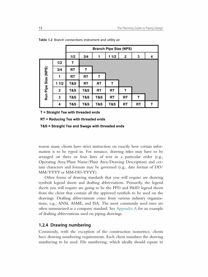
• Branch connection (can vary by piping class and may be included
within the piping classes)
• Line spacing
• Line spanning
3Before You Begin

Examples of these are shown in Tables 1.1�1.4.While line spacing charts and branch connection charts are fairly
straightforward, care must be taken with line spanning charts. Line span-
ning charts will provide layout guidance, but many load factors may affect
the posted spans. Final pipe spans must be confirmed during stress analysis.
While not vital, a chart worthy of adding to the above list is that for
nozzle projection. Projections (distance from the surface of a vessel or
tank to the face of the flanges) vary with nozzle size, flange rating, insula-
tion thickness, and reinforcing pad thickness. The minimum projection
Figure 1.1 Dummy leg.
4 The Planning Guide to Piping Design

allows for approximately 3 in. (76 mm) of pipe length between the shell
and a weld neck flange. This length is required for welding and removal
of stud bolts. An example of a Nozzle Projection Chart is Table 1.5.
A nozzle chart is useful for discussion with the mechanical group and
study work prior to the receipt of vendor drawings.
1.2.3 Drawing templates and drawing standardsDrawing templates are required for the drawings that are to be created for
the project. There are four common drawing templates for four plot sizes
depending on drawing type and/or scale factor:
Figure 1.2 Trunnion support.
5Before You Begin
• ANSI paper sizes used in the United States and Canada:
• A size—81/2v3 11v (e.g., standards).• B size—11v3 17v (e.g., construction isometrics).
• D size—22v 3 34v (e.g., Process Flow Diagrams (PFDs), Piping
and Instrumentation Diagrams (P&IDs), and piping arrangements).
• E size—34v 3 44v (e.g., plot plans, equipment location plans, and
key plans).
°
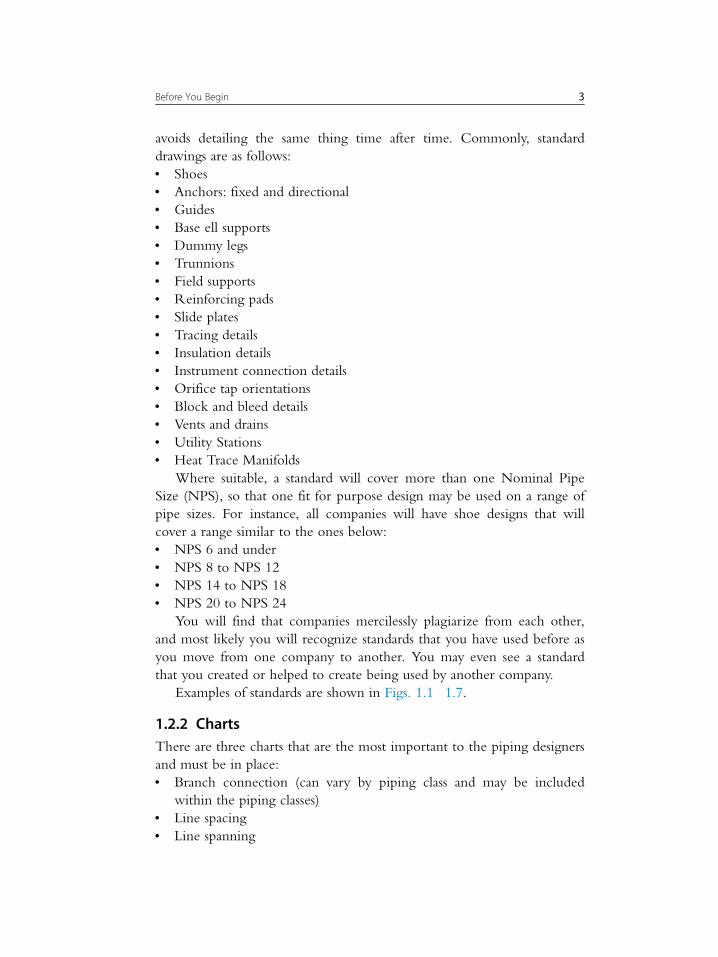
Figure 1.3 Base support.
6 The Planning Guide to Piping Design

• ISO A series paper sizes used in the rest of the world:
• A4—210 mm 3 297 mm (e.g., standards).
• A3—297 mm 3 420 mm (e.g., isometrics).
• A1—594 mm 3 841 mm (e.g., PFDs, P&IDs, and piping
arrangements).
• A0—841 mm 3 1189 mm (e.g., plot plans, equipment location
plans, and key plans).
Figure 1.4 Pipe shoe.
7Before You Begin
ANSI C (17v 3 22v) and ISO A2 (420 mm 3 594 mm) paper sizes
are usually reserved for reduced size plots of ANSI D and E, and ISO A1
and A0. This is due to being a convenient handling size while retaining a
large enough drawing size for clarity and mark-ups.
It is most likely that the client will have drawing templates for three
of the four drawing sizes, ANSI A, D, and E, or ISO A4, A1, and A0,
that they will require you to use on their project. For the construction
isometric template, ANSI B/ISO A3, the client will most often defer to
the engineering company. This is because, unlike the other drawings,
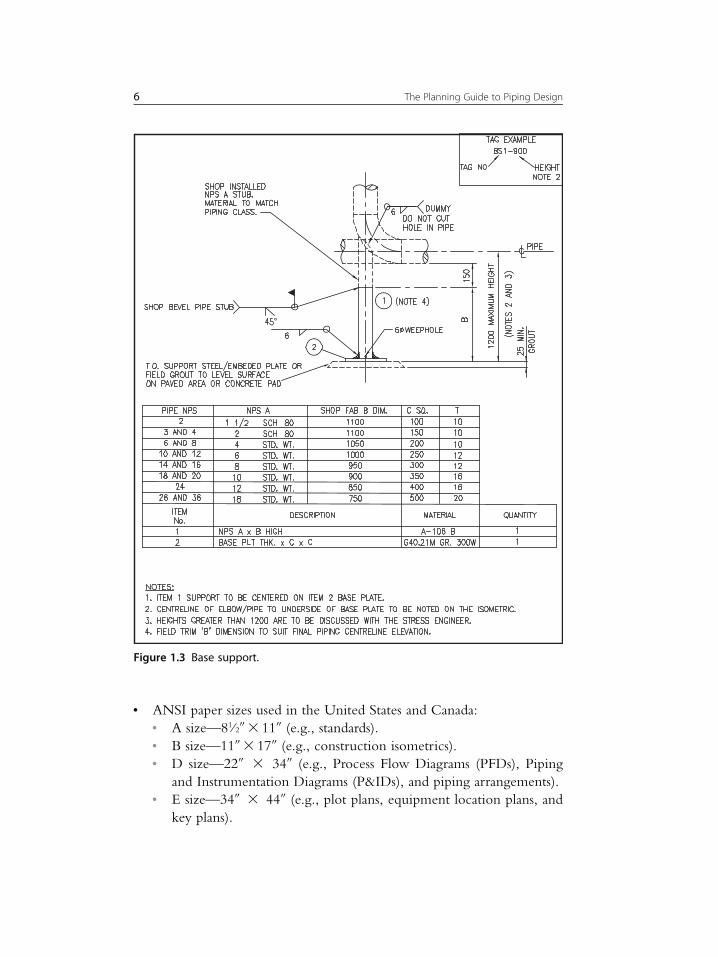
Figure 1.5 Directional anchor NPS 6 and under.
8 The Planning Guide to Piping Design
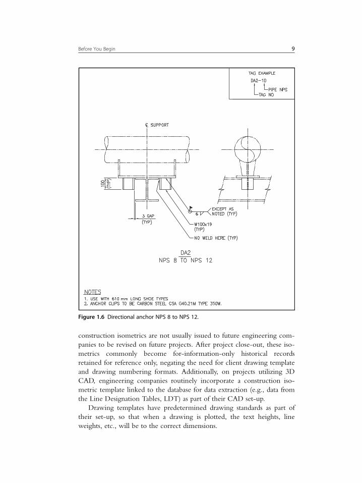
construction isometrics are not usually issued to future engineering com-
panies to be revised on future projects. After project close-out, these iso-
metrics commonly become for-information-only historical records
retained for reference only, negating the need for client drawing template
and drawing numbering formats. Additionally, on projects utilizing 3D
CAD, engineering companies routinely incorporate a construction iso-
metric template linked to the database for data extraction (e.g., data from
the Line Designation Tables, LDT) as part of their CAD set-up.
Drawing templates have predetermined drawing standards as part of
their set-up, so that when a drawing is plotted, the text heights, line
weights, etc., will be to the correct dimensions.
Figure 1.6 Directional anchor NPS 8 to NPS 12.
9Before You Begin

Drawing standards include the following:
• Titleblock with company logo
• Text heights
• Layering system
• Line weights
• Dimension styles
A client requirement to be investigated is the filling in of the title-
block. The document management software used by the client may be set
up to scrub meta-data from the attributes in the 2D CAD file and for this
Figure 1.7 Single block vent and drain.
10 The Planning Guide to Piping Design

Table 1.1 Branch connections process lines
reason many clients have strict instruction on exactly how certain infor-
mation is to be typed in. For instance, drawing titles may have to be
arranged on three or four lines of text in a particular order (e.g.,
Operating Area/Plant Name/Plant Area/Drawing Description) and cer-
tain characters and formats may be governed (e.g., date format of DD/
MM/YYYYor MM-DD-YYYY).
Other forms of drawing standards that you will require are drawing
symbols legend sheets and drafting abbreviations. Primarily, the legend
sheets you will require are going to be the PFD and P&ID legend sheets
from the client that contain all the approved symbols to be used on the
drawings. Drafting abbreviations come from various industry organiza-
tions, e.g., ANSI, ASME, and ISA. The most commonly used ones are
often summarized as a company standard. See Appendix A for an example
of drafting abbreviations used on piping drawings.
1.2.4 Drawing numberingCommonly, with the exception of the construction isometrics, clients
have drawing numbering requirements. Each client mandates the drawing
numbering to be used. File numbering, which ideally should equate to
Table 1.2 Branch connections instrument and utility air
12 The Planning Guide to Piping Design

Table 1.3 Line spacing chart

Table 1.4 Line spanning chart

the drawing number, is also mandated in order for the client to be able to
accept the drawing files back into the document management system and
be able to retrieve them when required. While numbering systems vary
by company, most have a hierarchy numbering system using abbreviated
identifiers along the following lines:
• Area of operation
• Facility
• Discipline, e.g., mechanical, piping
• Type of drawing, e.g., piping arrangement
• Three- or four-digit sequential drawing number
• Two- or three-digit sequential sheet number
Isometric drawing numbering will require separate investigation. An
often used practice is to include the line number as part of the drawing
number for easy identification. Sheet numbers identify longer runs where
a piping system has been broken into multiple isometric details for clarity,
e.g., SHT 1 OF 5, SHT 2 OF 5,. . .. . ...SHT 5 OF 5.
1.2.5 3D model numberingWhat is the model numbering convention to be used for the project?
Again, this may be a client or engineering company standard, but it must
Table 1.5 Nozzle projection chartFlange class rating
NPS 150 300 600 900 1500 2500
Min. outside projection
from shell to
face-of-flange
3/4 150 150 150 150 150 150
1 150 150 150 150 150 200
11/2 150 150 150 150 200 200
2 150 150 150 200 200 200
3 175 175 200 200 200 250
4 175 200 200 200 250 300
6 200 200 200 250 300 350
8 200 200 250 250 300 400
10 225 225 250 300 350 500
12 225 250 250 300 400 550
14 250 250 250 350 400 �16 250 250 300 350 400 �18 250 250 300 350 450 �20 275 275 300 350 450 �24 300 300 300 350 500 �
All dimensions are in mm.Dimensions do not include insulation or reinforcing pad thicknesses.
15Before You Begin

be decided right at the beginning of the project. If you are directed to
use a company standard, make sure that your client is in agreement.
These models will later have to be closed-out and renumbering/renaming
can cause considerable work that is likely not included in the budget. As
with drawing file numbering, models require a file numbering system
that is approved by the client. In today’s 3D integrated design world,
where all disciplines are referencing the other disciplines’ models, and
working more-or-less in real time, you and your designers must inti-
mately know the model numbering system. This is in order to correctly
name the piping models and identify other disciplines’ models that are
required to be referenced.
One way that I have seen model numbering done is to follow the
Engineering Work Package (EWP) numbering. This makes sense because
assembling information is not just the domain of the designers. Often the
CAD support group or the material control group will be requested to
generate reports of a particular EWP, or a group of EWPs, and a com-
mon numbering system for the models and the EWPs will help to locate
and compile the information. Common reports are as follows:
• Material Take Off (MTO), either bulk or item specific for
• pipe and fittings
• insulation
• valves
• shop material (also known as fabrication material)
• field material (also known as erection material)
• Weld count and diameter inches of welding
• Weights of materials
As all of the reports are generated from the databases that are built as
the models are developed, having a direct correlation to the EWP num-
ber makes life easier for the downstream people, such as material control-
lers and purchasers.
1.2.6 Material commodity codesMaterial commodity codes are a piping component numbering system
used for the identification, ordering, and tracking of materials.
Originating in the 3D model material library database, these numbers
appear on the MTO reports and the isometric Bills of Material (BOM)
and in the documentation used by the purchasers, suppliers, fabricators,
and warehousing. These codes are commonly an alpha-numeric string
16 The Planning Guide to Piping Design

(e.g., “F” for flange) which uniquely identifies a component. Although
ISO 15926 is making inroads, industry standards do not currently exist
for material commodity coding of piping components, so companies have
to develop their own key element identifiers or engage the services of an
outside consultant to develop these for them. So why should this be a
concern for the piping lead? If you are using your company piping classes
and the material commodity coding is in place, then for the most part
you and your designers will have no interest in material commodity codes
other than curiosity. However, if material commodity codes are to be
used on the project, and development is required because your company
does not currently have a commodity coding system, or the client wants
you to use their commodity coding system, then you will need to take
into consideration the time involved for the development and implemen-
tation by the material control group and IT. Development and implemen-
tation can impact your ability to start 3D modeling.
As not all projects use material commodity codes, you will have to
ascertain whether they are to be used on your project or not. If they are,
are they to be to your company’s standards or the client’s? Will the adop-
tion of a commodity code numbering system cause you any delays?
1.3 SPECIFICATIONS
Many clients and engineering companies will have a set of company
specifications for each discipline built on code, safety and insurance
requirements, and preferred engineering practices. Most specifications are
engineering related, but some are directly related to the layout of the
plant. As has already been said, these are related to walkways, platform
and ladder requirements, egress and ingress, and equipment spacing, but
they often also include other information of importance to the piping
designers such as pump and exchanger piping layouts, and transportation
requirements for modules and spools. As the lead, you must review these
and catalog for your team all of the pertinent specifications and where
they may be found, commonly on the company network or a client web
based site.
The most obvious and essential specifications to be secured are the
piping classes.
17Before You Begin

1.3.1 Piping classesThe piping classes are one of the most important specifications for the
piping designer. These are developed by the piping engineer, and most
often have been applied on numerous projects, sometimes for many years.
Piping classes are developed around the applicable piping code, and list
components and materials manufactured to the standards listed within the
code. This allows component use with no further investigation and avoids
calculations and material selections being repeated time and time again
for the same application. The piping classes list the following:
• ASME code (B31.1 in power plants and B31.3 in process plants)
• Fluid service (process commodities)
• Flange rating
• Corrosion allowance
• Temperature range
• Pressure limits
• Non-Destructive Examination (NDE)
• Heat treatment
• NPS range, and pipe schedule wall thickness (WT) or calc. wall
• End preparation
• Valves
• Listed standards/components and materials accepted by the code for
• pipe
• fittings
• flanges
• orifice flanges
• unions
• plugs
• nipples
• spectacle blinds, spades, and spacers
• olets
• gaskets
• bolting
An example of a piping class is Table 1.6.
Piping classes have an abbreviated identifier. An example of this is the
following three-digit identifier and Table 1.7:
• Flange rating
• Service
• Pipe material
18 The Planning Guide to Piping Design
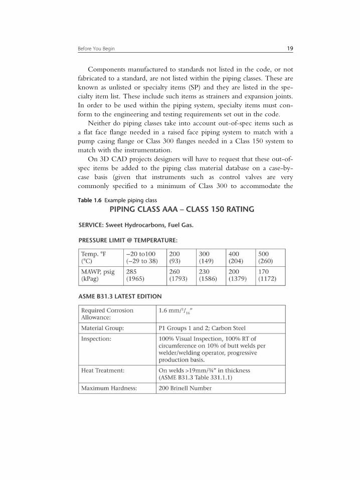
Components manufactured to standards not listed in the code, or not
fabricated to a standard, are not listed within the piping classes. These are
known as unlisted or specialty items (SP) and they are listed in the spe-
cialty item list. These include such items as strainers and expansion joints.
In order to be used within the piping system, specialty items must con-
form to the engineering and testing requirements set out in the code.
Neither do piping classes take into account out-of-spec items such as
a flat face flange needed in a raised face piping system to match with a
pump casing flange or Class 300 flanges needed in a Class 150 system to
match with the instrumentation.
On 3D CAD projects designers will have to request that these out-of-
spec items be added to the piping class material database on a case-by-
case basis (given that instruments such as control valves are very
commonly specified to a minimum of Class 300 to accommodate the
Table 1.6 Example piping class
19Before You Begin

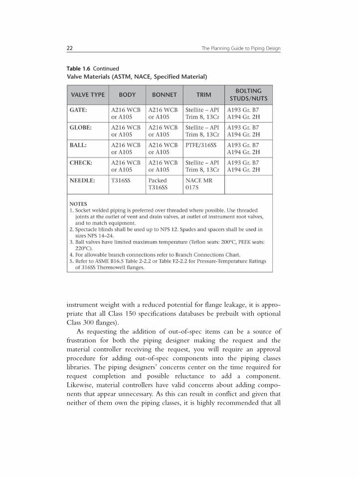
Table 1.6 Continued
20 The Planning Guide to Piping Design

Table 1.6 Continued
21Before You Begin
instrument weight with a reduced potential for flange leakage, it is appro-
priate that all Class 150 specifications databases be prebuilt with optional
Class 300 flanges).
As requesting the addition of out-of-spec items can be a source of
frustration for both the piping designer making the request and the
material controller receiving the request, you will require an approval
procedure for adding out-of-spec components into the piping classes
libraries. The piping designers’ concerns center on the time required for
request completion and possible reluctance to add a component.
Likewise, material controllers have valid concerns about adding compo-
nents that appear unnecessary. As this can result in conflict and given that
neither of them own the piping classes, it is highly recommended that all
Table 1.6 Continued
22 The Planning Guide to Piping Design

requests be vetted through the piping engineer for approval; the piping
engineer is the custodian of the piping classes, and is the appropriate per-
son for the authorization and expedition of changes and additions.
Calculated wall, or “calc. wall” as it is often listed in the piping classes,
is another subject to be addressed by yourself and the piping engineer as
soon as possible. If you start the modeling with the calculated wall it can
later become a problem to update the models once the pipe schedule
has been determined. This is particularly true when a piping class encom-
passes several process commodities and the NPS ranges of pipe vary in
calculated WT according to the differing design conditions.
I strongly suggest that you discuss this sooner rather than later with
the piping engineer and the material controller. I also strongly suggest
that the calculated wall be based on the worst case design conditions for
the piping class. The potential for mistakes in design, fabrication, and
material control when WT choices exist for a given pipe size can out-
weigh any cost saving that may be realized on the pipe and fittings them-
selves. It is also possible that a calculated pipe schedule may prove to be
less commercially available than a slightly heavier pipe schedule. Schedule
160, for instance, is usually very available, whereas Schedule 140 usually
is not as available.
Finally, the set-up of the piping classes for the use by the designers
when creating the 3D models is a joint exercise between the material
control group who create the database content and the CAD support
group who ensures the functionality. Prior to the start of modeling you
Table 1.7 Piping class identifiers
23Before You Begin

must have these piping classes databases checked against the original
(likely in Word format) specifications. The accuracy of all MTO reports
and BOM lists on the isometrics rests on the accuracy of the piping class
databases and the importance of ensuring the integrity of these databases
cannot be overstated.
Having said this, it is also strongly recommended that the piping
designers be required to habitually refer back to the original specifications.
An impression exists on 3D projects that reference to the original piping
classes and branch charts is unnecessary because the choices of available
components, including branch fitting choices, have been predetermined and
limited per the piping class databases. This is to say that the belief is that the
databases provide all the information needed about the allowable piping
components (spec driven). However, mistakes in set up and checking do
happen, and as a safeguard all your designers should be held accountable to
understand the root documents and to verify differing information.
Once the piping classes have been approved they are frozen for the
duration of the project. Changes may happen to the piping classes during
the project, but these must follow a deviation process.
1.4 PROCEDURES
Projects revolve around procedures, and without these you cannot
execute your project. Procedures are the “Highway Code” that keeps
everyone on the same page. However, procedures are often either poorly
written or not enforced, which is as bad as having no procedure. Read
the procedures thoroughly and understand them, because it will be up to
you to enforce them later, and possible to expand on them.
Engineering company procedures will commonly include the
following:
• Stick files
• Interdiscipline drawing reviews, both internal (engineered drawings)
and vendor
• Line numbering
• Stress analysis
• CAD set-up and support
• 3D model reviews
• Checking
24 The Planning Guide to Piping Design

• Manhour estimating
• Progress reporting
• Management of change
Client procedures have been developed to standardize the drawing
and model deliverables. These include the following:
• Drawings to be as-built
• Project close-out
These last two procedures are usually owned by your client’s document
management department and enforced by your own company’s document
management. That does not mean though that you do not have a say.
These procedures have areas of overlapping accountabilities between
designers and document controllers. Because no procedure is perfect for all
situations, the client’s document management department is most often
conducive to small deviations and are willing to work with you from a
designer’s input point of view. On smaller projects you may well have
direct access to speak with them, whereas on larger projects you will have
to request a deviation through your project management team. Deviations
to client procedures identified during the initial set-up should be documen-
ted in the Project Execution Plan (PEP). You will need to inform your
project management team of all deviations to the document management
procedures initiated by yourself and agreed to by the client.
The following are brief discussions on all the above-mentioned proce-
dures/activities that you, as a piping lead, must be aware of, and that the
piping group has a direct or indirect involvement in. In Chapter Two,
CAD and Design Automation in Piping Design, we will discuss in more
detail the procedures below that the piping group manage directly or
have a major involvement in.
1.4.1 Stick filesWhether electronic computer based or in hard copy paper format, a stick
file is the best tool to use for capturing and managing changes. It is a cen-
tral depository for all mark-ups from all disciplines and ensures that all
changes are clearly communicated and surprises are avoided.
The trend in recent years has been to do everything in an electronic
computer based environment and shun hard copy paper formats as ineffi-
cient and undesirable in the context of project record keeping. This is a
perfect example of where the worlds of manual and electronic procedures
have collided. While possible to utilize an electronic stick file procedure
25Before You Begin

using a mark-up tool such as Adobe Reader or Bluebeam Revu, in prac-
tice it is still very much human nature to defer to marking up a hard
copy print of a drawing due to this still being easier and more familiar.
I advocate that a hard copy stick file is still best, scanned prior to back-
drafting for record.
A decision will need to be made on either an electronic or a manual
stick file procedure.
If electronic is the choice, then you will need to know where the draw-
ings are to be deposited and how they are to be accessed and edited with
mark-ups. You will also need to receive alerts when comments are made.
Similarly, if manual is the choice, you will need to have a procedure
around mark-ups and notification, and you will need to identify an area
where your master stick files will reside. Preferably this will be close by
and with reference tables to lay the stick files on. Ideally, you will have
room for roller boards. Roller boards, where the drawings are tapped down,
work wonderfully to stop people wandering off with your stick files.
1.4.2 Interdiscipline drawing reviewsDrawings are produced in every project. Drawings represent the culmina-
tion of the design, and a finalization of all discussions and decisions to
date. A review by all disciplines that have had input is required in order
to establish that the designs are as expected by all stakeholders. It is your
accountability to ensure that the piping drawings are made available for
review and comment. Likewise to master stick files, interdiscipline draw-
ing reviews may be by electronic or hard copy methods, either through
network access or hard copy circulation. Electronic reviews require a net-
work place where the drawings are stored. Hard copy reviews require a
circulation procedure and filing cabinets for storage. Both review methods
require a way of sending notifications to the reviewers.
Vendor drawings also require a review procedure. While you are not
responsible for initiating vendor drawing reviews, you are responsible to
ensure the integrity and availability of the latest vendor drawings for
reference and mark-up by your team.
Regardless of the interdiscipline drawing review procedure employed,
the document control group play a key role. You will need to liaise with
the document control lead for an understanding of their processes and to
ensure that your needs are going to be met. In the case of electronic
mark-ups, it may also be needed to arrange training for your team on the
document control software.
26 The Planning Guide to Piping Design

1.4.3 Line numberingLine numbering is a standard. The elements that make up a line number
and the order of placement are standardized by each client or engineering
company. The sequencing of the elements may change between compa-
nies, but all line numbers contain the following:
• Piping class
• NPS
• Sequential line number
• Insulation thickness and type
• Tracing requirements
Some standards may also include the following:
• Unit number
• Commodity abbreviation of the process fluid
When it comes to the task of assigning line numbers to the P&IDs, a
procedure is required. Does a line reduction within a header system con-
stitute the assignment of another line number? Is a pump suction line that
splits to a pair of A and B pumps two or three line numbers? You will
discover that there are different thoughts on the subject. Line numbering
may not be the responsibility of the piping group, and it may fall under
the auspices of the process engineers’, but you as a piper have a vested
interest that requires discussion. The overuse of line numbers can result in
piping runs being broken down into a greater number of isometrics.
Whoever does it, and to whatever procedure, line numbering needs
to be done sooner rather than later, as modeling cannot begin without
line numbers having been assigned.
1.4.4 Stress analysisHow are you going to interface with the stress group? Which lines will
be stressed first? How will you track stress analysis? Where will you store
the stress mark-ups? And how will the stress requirements be disseminated
to the pipers? These are questions that we will investigate in more detail
in Chapter Two, CAD and Design Automation in Piping Design. It is a
complex matter, and not one to be overlooked. If you do not have a
company procedure to fall back on, you will need to develop one.
1.4.5 CAD set-upCAD support is a major contributor to the success of any project. Ensure
that the appropriate company and client CAD procedures are going to be
used:
27Before You Begin

• Maintaining databases
• Plotter and printer set-ups
• Model back-ups, usually nightly
• Project close-out
The above will be of little interest to the designer and should be hap-
pening seamlessly in the background. However, there are project set-up
requirements that are of particular importance in order for the designer
to do his/her work. But, because there are many ways of doing things,
the CAD support group will require direction from you, the piping lead,
for the following to be input:
• Work areas
• Client or company piping classes
• Client or company piping standards, e.g., shoes, base ell supports,
anchors, and guides
• Color coding of pipe, equipment and temporary steel per the client or
company standards. For example is pipe to be color coded
• by piping classes: Class 150, 300, 600, etc.
or
• by commodity: sub-sets of water, steam, oil, gas, etc.
• Link for automatic data extraction from the LDT into the isometric
titleblocks
• Clash report procedure
Another consideration is the generation of reports and the reports’
format. Other groups will rely on reports generated from the databases
for such as purchasing and estimating purposes. Establishing the reporting
needs is an essential part of the CAD set-up. The databases used for these
reports are built during the development of intelligent P&IDs and 3D
models, and consist of the following examples:
• LDT
• Equipment Lists
• Instrument Lists
• Specialty Item Lists
• Valve Lists
• Corrosion Coupon Lists
• Car Seal Lists
• Spring Supports List
• Bulk Material Reports
• MTO Reports
• Weld Diameter Inch Reports
• Weights of Materials Reports
28 The Planning Guide to Piping Design

A project directory structure is also required where drawings and mod-
els are deposited. This structure should ideally be mirrored by each disci-
pline so that finding models is easy for all. As a side note, designers love to
copy into their personal drives and work from there on unofficial models.
This practice must be discouraged as it can cause obvious communication
problems. There is nothing wrong with copying to do some studies, but
the results must be imported into the master model as soon as possible, and
all work should primarily only be done in the master model.
Which software and version of that software are you using? Lock it in
and do not let anyone tell you that an upgrade during your project is an
easy matter. The software and version may be mandated by the client, in
which case the decision is off of your shoulders, but if it is a company
choice do not change once you start. Changing the current version to an
untested version during a project inevitably leads to untold grief and extra,
unbudgeted hours. No disrespect to the CAD support group, but even if
they tell you that it has been tested, do not let your project be the ultimate
test case for the newest version, no matter how much they protest that this
will solve many of the problems currently encountered. Testing is nebulous,
and their testing of some functionality and file conversion on a small scale
will not be representative of the full usage by the designers and conversion
of dozens or possibly hundreds of models and databases.
Security is another issue to be addressed. Your client may be very
interested in this aspect of his/her project, but even if they are not, it is in
your own interest to make sure that you are comfortable with the security
measures that are in place. Security means access. Who has access to edit
the models? Minimally, there should be restrictions on the following:
• Each discipline. A discipline must not be able to edit the other disci-
plines’ models.
• Stages of design. Freeze models when they are ready for checking.
Unfreeze but freeze again after the changes required by checking have
been made. Designers are perfectionists and if there are no controls
stopping them from doing so, they may go back into their models and
make changes during checking and even after it has been Issued For
Construction (IFC). While keenness can be admired, unmanaged and
unchecked changes that surface will cause an embarrassment at the
least, and can lead to other costly problems.
Several other decisions that you may also be required to have input
into with the CAD support manager, office manager, and project man-
ager are as follows:
• The number of CAD stations you will need.
29Before You Begin

• The types of software and number of licenses.
• The space and furniture requirements for common areas, e.g., plotters,
printers, stick files, filing cabinets, lay down tables.
If manual stick file and interdiscipline drawing reviews are being used,
when you meet with the office manager be sure to order all of the stamps
you will need, i.e., a date stamp, “RECEIVED,” “MASTER STICK
FILE,” “WORKING COPY,” “PIPING COPY,” “CHECK PRINT,”
“SUPERSEDED,” and “FOR INFORMATION ONLY.” You could
also order stamps for “STRESS COPY” and “FOR BID PURPOSES
ONLY. NOT TO BE USED FOR CONSTRUCTION,” but these can
be added to the drawings as blocks at the time of issue.
Designers require lots of support from the CAD support group. You
will require a clear line of communication between the two groups for
the following:
• General questions about CAD execution and CAD commands
• Copying of databases
• Modeling of specialty items
• Adding of specialty items and out-of-spec components into the piping
specifications and material libraries
• Retrieving lost data and corrupted files
Larger engineering companies may well utilize software whereby a
request is sent and a ticket number assigned. Smaller companies may well
utilize an e-mail request. However this is to be done, make sure that you
have a documented procedure that can be distributed to the designers.
1.4.6 3D model reviewsModel reviews are commonly conducted at the 30%, 60%, and 90%
stages of design completion, and involve buy-in by all stakeholders up to
that stage. Definitions are required for each of these stages so that every-
one has the same understanding of what is to be accomplished prior to
and during the reviews, and the designers stay focused on the parameters
to be established leading up to the reviews. The best way for this to be
accomplished is to have written documentation with a model review matrix.
1.4.7 CheckingIt goes without saying that checking is a requirement of any project, but
how are you going to go about this? What are you going to check? You
need a checking procedure to give guidance and ensure consistency.
30 The Planning Guide to Piping Design

1.4.8 Manhour estimatingManhour estimating and manpower planning can be quite a daunting
task, and there are books written on this subject alone. Generally speak-
ing, companies employ schedulers for this task, but as a lead you will be
required to have input into the piping hours budget and piping schedule.
The schedulers will be of valuable assistance in helping you with this task.
However, it does not end there. After the piping budget and piping
schedule have been established, the task of work allocation—literally the
decision on which designers will work in which areas and according to a
priority that supports the schedule—rests with the piping lead.
A sometimes overlooked requirement for manhour estimating and
manpower planning is to know the deliverables. If these are not clear, do
not make assumptions. Get direction from your project management
team on the client’s expectations. This is to ensure that you have a clearly
documented basis for your estimating that can be used later to support a
revision to the budgeted hours should the need arise.
1.4.9 Progress reportingYour project management will expect progress reports. Larger engineer-
ing companies will have their own procedures to accomplish this. If you
are in a smaller company, chances are that you will need to establish a
form of reporting in conjunction with the project management.
Reporting is essential, not just because periodic payments from the client
may be tied to the progress, but because it is necessary to understand
where you are in the project, whether or not you are staying within the
budgeted hours, and to identify when you are going off track in order to
take corrective action.
1.4.10 Management of changeChange is inevitable in any project, and management of change is crucial
to the success of the project. You must manage the trends and scope
changes for the piping effort. A trend is an unbudgeted event that
increases the number of hours required to complete an activity. For
instance, a deviation to a piping class or vendor information that arrives
later than planned and causes delays and rework constitutes a trend. A
scope change is a modification, deletion, or addition to the original scope
that was not budgeted for, such as the addition of a piece of equipment.
31Before You Begin

In order to recognize trends and scope changes, a clear understanding of
the original project scope and budget is required.
Scope changes are quite easy to spot and usually emanate from the cli-
ent, whereas trends can be contentious and usually have to emanate from
you, the piping lead. Are the hours that are being expended normal
design development or are they a trend? You are going to find yourself in
this debate many times in your career. The simple answer is that there are
no simple answers. However, situations such as those below are clues:
• If you have to change your plans and focus due to delayed arrival of
information, leading to productivity being lost, this is a trend.
• If you were given information with assurances as to the completeness
and accuracy of this information for the level of design, and you have
to rework your design because it turned out not to be so, this is a
trend.
• If you were required to move ahead with preliminary information
into detailed design and later, when firmer information is available,
have to rework the design, this is a trend.
• If you or your group has to spend an abnormal amount of time assist-
ing another department or a vendor, this is a trend.
If for whatever reason you find yourself losing productivity and/or
reworking a design more than once and are in danger of exceeding the
budgeted hours, discuss the situation with your project engineer. A trend
may be in order.
You will learn that timing is everything and design developments,
such as a line size increase, or scope changes, such as a pump addition,
that come during the earlier study stage can be accommodated quite
readily without much, if any, schedule impact. But try accommodating
the same just before IFC and you will be looking at significant rework,
schedule delays, and cost impacts.
The surprising thing, considering its importance, is that managing
change is often done poorly or not at all. Formally raising, approving/
rejecting, and documenting these will avoid misunderstandings and
wasted hours. I have seen more than one project where the lack of docu-
mentation caused significant discord between the engineering company
and the client. Clients have a tendency to request changes throughout the
project and consider them design development, not trends or scope
changes. Engineering companies have a tendency to jump to attention
and rush in to accommodate the client. The client believes that his/her
requests are going to be accommodated without extra cost or schedule
32 The Planning Guide to Piping Design

impact while the engineering company assumes that the client realizes
otherwise. They are not on the same page, and likely will not be until
much later, after further discussions, possibly some hard feelings, and
likely after all the changes have already been made.
We must generate change notices to capture the impact that trends or
scope changes will have or are having on the piping effort. This docu-
mentation allows for a time of assessment to cost and schedule and for a
conscious choice to be made on how to proceed. Are the changes neces-
sary? For example, are they safety related, or are they just nice to have?
Can something be done about the potential productivity loss related
issues?
Your project management will expect change to be recognized, docu-
mented, and submitted for approval. As the eyes and ears of the piping
group, the piping lead is expected to keep his finger on the pulse, and not
jump the gun and allow unapproved design changes nor keep reworking
the same area due to someone else’s inability to make up his/her mind.
You are expected to see change coming, to anticipate the consequences,
and to raise flags ahead of time. Do not put yourself in the unenviable
position of trying to explain later why you are going over on budget and
schedule. You may end up making changes back to the original design
and lose credibility as a lead. Only a junior would use the excuse that
someone else told them to do it. Do not forget that you are a senior
member of the team with a budget that you are responsible for.
It is important that trends and scope changes be addressed as soon as
possible, but you will have very little control over how long these will
take. There are three options:
• Continue with the design as planned until the change is approved,
recognizing that the longer it takes to be approved the more work
there may be to undo in the design.
• Incorporate the changes into the design as if they are approved. For
this you must get assurances from the project team in writing that the
paperwork to proceed is a formality and will be forthcoming.
• Put the design in question on hold until approval is received.
The golden rule is that without an approved trend or scope change,
no changes are to be made. This is a very reasonable, necessary, and
important requirement for the project, and all companies should have a
procedure for submission and approval/rejection. Your company should
have forms for trending and scope changes. They will not always have the
33Before You Begin

same title at each company, but will be along the lines of “Engineering
Notice of Trend” and “Scope Change Request.”
1.4.11 As-builtsIt may seem unnecessary to consider as-builts at the beginning of the
project, given that it is one of the last tasks to be completed. However,
you will need to establish exactly what your client requires to have as-
built in order to complete your manhour estimates. Your client may only
require this of critical documents and will define “critical” for you.
Critical documents can be defined as documentation that government
regulatory bodies and the company deem must be kept current for the
continued safe operation of a facility.
While by no means an exhaustive list, the documents generally listed
that involve the piping group are as follows:
• P&IDs
• LDT
• Plot plan and equipment location plans
• Underground piping plans
• Heat tracing (commonly hot oil, steam, or glycol)
It is possible that you may also be required to as-built the 3D models
and the piping arrangements.
The client procedure must list and give direction in the documents to
be as-built.
Depending on whether your company or the client is handling the
construction management, the client or company procedures must give
direction on
• how the as-built changes will be captured, e.g., redline mark-ups in
the field
• how the as-builts are to be turned over to the engineering group
• how the engineering company is to turn the completed as-built docu-
mentation over to the client
Internally, at your engineering company, you must plan for the
following:
• Reviewing the as-builts, i.e., that the noted changes that occurred
during construction were documented and approved
• Drafting and checking of the field collected as-built information
• Sign-off
34 The Planning Guide to Piping Design
1.4.12 Project close-outAt the end of the project, a close-out will be required. This generally
involves handing over all the models, databases and drawings to your
engineering company’s document control group for close-out with the
client’s document control group. Make sure that you have an internal
close-out procedure and a close-out procedure from the client, and that
you fully understand the requirements of both. If one or both of these
has not been provided, you may need to develop them in conjunction
with your own people and the client.
1.5 PIPING EXECUTION PLAN
There are two key documents that are the basis for the project: the
Design Basis Memorandum (DBM) and the Project Execution Plan (PEP).
A Piping Execution Plan and a Design and Drafting Execution Plan will
form part of the PEP, and you as the piping lead are expected to be a lead-
ing contributor in the writing of these sections. The Piping Execution
Plan may be a section unto itself or it may be a subset of the Design and
Drafting Execution Plan.
The Piping Execution Plan and the Drafting Execution Plan are where
all the decisions that have been made are captured in writing. General deci-
sions on drafting that involve all disciplines, such as CAD software, are cap-
tured in the Design and Drafting Execution Plan, and specific piping
related decisions are captured in the Piping Execution Plan.
The following is a brief discussion of the DBM and the PEP, as they
are the guiding documentation for you and your designers and the basis
for everything that is to follow.
1.5.1 Design Basis Memorandum (DBM)The DBM defines the project scope and describes the technical basis for
detailed engineering. The typical content of a DBM includes the follow-
ing sections:
• Project Overview and Facility Description
• Facility Design Basis, e.g., Specifications and Standards
• Safety Design Basis
• Process Design Basis
35Before You Begin

• Civil and Structural Design Basis
• Mechanical Design Basis
• Electrical Design Basis
• Instrumentation and Controls Design Basis
• Any additional relevant basis information
1.5.2 Project Execution Plan (PEP)The PEP describes how the project will be executed and typically
contains the following sections:
• Cost Estimate
• Schedule
• Organization Plan
• Project Controls Plan
• Quality Assurance Plan
• Safety and Health Plan
• Regulatory Compliance Plan
• IT Plan
• Contracting and Procurement Plan
• Document Control Plan
• Engineering Execution Plan
• Design and Drafting Execution Plan
• Construction Execution Plan
• Commissioning Plan
Your designers must read and understand these documents because
they constitute the official instruction for the project that everyone has
to follow. Two key sections in the PEP are the Contracting and
Procurement Plan and the Construction Execution Plan.
1.5.3 Contracting and Procurement Plan and ConstructionExecution PlanThe Contracting and Procurement Plan and the Construction Execution
Plan outline the procurement and construction philosophies and are the
basis from which many other decisions and planning by the piping lead
will stem:
• Modularized and field erected piping splits
• EWP boundaries
• Model boundaries
• Shop and field material splits
36 The Planning Guide to Piping Design

• Procurement splits
• EWP drawing packages
• Scopes of Work (SOW)
These documents may be in a preliminary stage when you first start
and you may have to help define the contents. Failure to clearly establish
the Procurement and Construction Execution Plans at an early stage and
starting into detailed design without them can result in material, model-
ing, and drawing boundaries that may not later match the final desired
EWP breakdown. This can lead to confusion for the fabricators and erec-
tors, or added hours to rectify the splits.
1.6 CONCLUSION
You must investigate and secure all of the above, and should any of
the above not be readily available, you must raise the flags with your proj-
ect management team as to where it may be secured from and adopted
for the project.
There is a lot to consider, and many questions to be answered, and
much will be discussed in more detail in the subsequent chapters.
37Before You Begin