Embed Size (px)
Citation preview
Outdoor Condensing Units
for Refrigeration Networks
C6.1.4/1109-1110/E
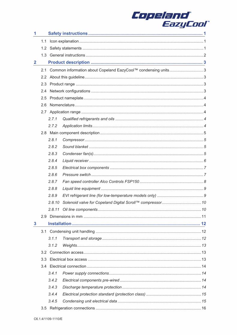
1 Safety instructions ............................................................................................ 1
1.1 Icon explanation ................................................................................................................. 1
1.2 Safety statements .............................................................................................................. 1
1.3 General instructions ........................................................................................................... 2
2 Product description .......................................................................................... 3
2.1 Common information about Copeland EazyCool™ condensing units ............................... 3
2.2 About this guideline ............................................................................................................ 3
2.3 Product range .................................................................................................................... 3
2.4 Network configurations ...................................................................................................... 3
2.5 Product nameplate ............................................................................................................. 4
2.6 Nomenclature ..................................................................................................................... 4
2.7 Application range ............................................................................................................... 4
2.7.1 Qualified refrigerants and oils ................................................................................ 4
2.7.2 Application limits ..................................................................................................... 4
2.8 Main component description .............................................................................................. 5
2.8.1 Compressor ............................................................................................................ 5
2.8.2 Sound blanket ........................................................................................................ 5
2.8.3 Condenser fan(s) .................................................................................................... 5
2.8.4 Liquid receiver ........................................................................................................ 6
2.8.5 Electrical box components ..................................................................................... 7
2.8.6 Pressure switch ...................................................................................................... 7
2.8.7 Fan speed controller Alco Controls FSP150 .......................................................... 8
2.8.8 Liquid line equipment ............................................................................................. 9
2.8.9 EVI refrigerant line (for low-temperature models only) .......................................... 9
2.8.10 Solenoid valve for Copeland Digital Scroll™ compressor .................................... 10
2.8.11 Oil line components .............................................................................................. 10
2.9 Dimensions in mm ........................................................................................................... 11
3 Installation ....................................................................................................... 12
3.1 Condensing unit handling ................................................................................................ 12
3.1.1 Transport and storage .......................................................................................... 12
3.1.2 Weights................................................................................................................. 13
3.2 Connection access ........................................................................................................... 13
3.3 Electrical box access ....................................................................................................... 13
3.4 Electrical connection ........................................................................................................ 14
3.4.1 Power supply connections.................................................................................... 14
3.4.2 Electrical components pre-wired .......................................................................... 14
3.4.3 Discharge temperature protection ........................................................................ 14
3.4.4 Electrical protection standard (protection class) .................................................. 15
3.4.5 Condensing unit electrical data ............................................................................ 15
3.5 Refrigeration connections ................................................................................................ 16
C6.1.4/1109-1110/E
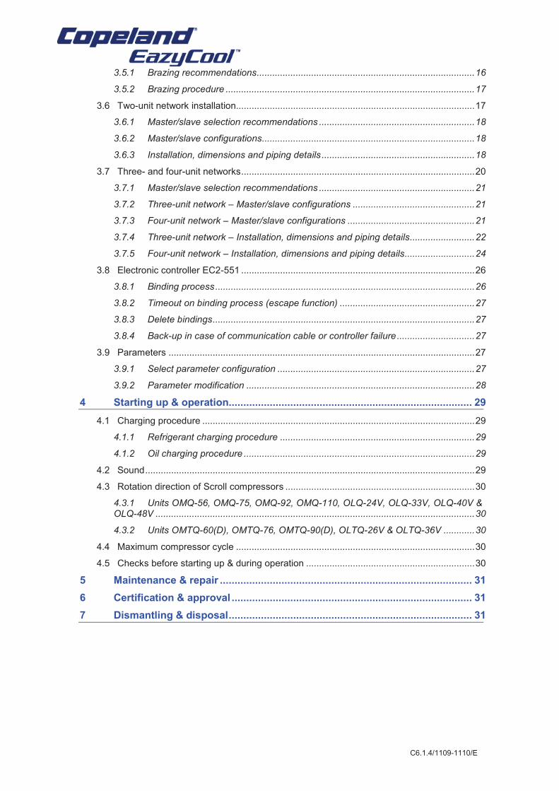
3.5.1 Brazing recommendations.................................................................................... 16
3.5.2 Brazing procedure ................................................................................................ 17
3.6 Two-unit network installation............................................................................................ 17
3.6.1 Master/slave selection recommendations ............................................................ 18
3.6.2 Master/slave configurations.................................................................................. 18
3.6.3 Installation, dimensions and piping details ........................................................... 18
3.7 Three- and four-unit networks .......................................................................................... 20
3.7.1 Master/slave selection recommendations ............................................................ 21
3.7.2 Three-unit network – Master/slave configurations ............................................... 21
3.7.3 Four-unit network – Master/slave configurations ................................................. 21
3.7.4 Three-unit network – Installation, dimensions and piping details......................... 22
3.7.5 Four-unit network – Installation, dimensions and piping details........................... 24
3.8 Electronic controller EC2-551 .......................................................................................... 26
3.8.1 Binding process .................................................................................................... 26
3.8.2 Timeout on binding process (escape function) .................................................... 27
3.8.3 Delete bindings ..................................................................................................... 27
3.8.4 Back-up in case of communication cable or controller failure .............................. 27
3.9 Parameters ...................................................................................................................... 27
3.9.1 Select parameter configuration ............................................................................ 27
3.9.2 Parameter modification ........................................................................................ 28
4 Starting up & operation................................................................................... 29
4.1 Charging procedure ......................................................................................................... 29
4.1.1 Refrigerant charging procedure ........................................................................... 29
4.1.2 Oil charging procedure ......................................................................................... 29
4.2 Sound ............................................................................................................................... 29
4.3 Rotation direction of Scroll compressors ......................................................................... 30
4.3.1 Units OMQ-56, OMQ-75, OMQ-92, OMQ-110, OLQ-24V, OLQ-33V, OLQ-40V & OLQ-48V ........................................................................................................................... 30
4.3.2 Units OMTQ-60(D), OMTQ-76, OMTQ-90(D), OLTQ-26V & OLTQ-36V ............ 30
4.4 Maximum compressor cycle ............................................................................................ 30
4.5 Checks before starting up & during operation ................................................................. 30
5 Maintenance & repair ...................................................................................... 31
6 Certification & approval .................................................................................. 31
7 Dismantling & disposal ................................................................................... 31
C6.1.4/1109-1110/E 1
1 Safety instructions
Copeland EazyCool™ condensing units are manufactured according to the latest European and US Safety Standards. Particular emphasis has been placed on the user's safety.
These condensing units are intended for installation in machines and systems according to the EC Machines directive. They may be put to service only if they have been installed in these systems according to instructions and conform to the corresponding provisions of legislation. For relevant standards please refer to Manufacturers Declaration, available on request.
These instructions should be retained throughout the lifetime of the compressor as well as the condensing unit.
You are strongly advised to follow these safety instructions.
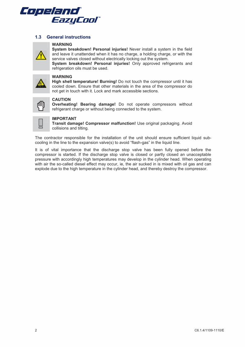
1.1 Icon explanation
WARNING This icon indicates instructions to avoid personal injury and material damage.
CAUTION This icon indicates instructions to avoid property damage and possible personal injury.
High voltage This icon indicates operations with a danger of electric shock.
IMPORTANT This icon indicates instructions to avoid malfunction of the compressor.
Danger of burning or frostbite This icon indicates operations with a danger of burning or frostbite.
NOTE
This word indicates a recommendation for easier operation.
Explosion hazard This icon indicates operations with a danger of explosion.
1.2 Safety statements
§ Refrigerant compressors must be employed only for their intended use.
§ Only qualified and authorized HVAC or refrigeration personnel are permitted to install, commission and maintain this equipment.
§ Electrical connections must be made by qualified electrical personnel.
§ All valid standards for connecting electrical and refrigeration equipment must be observed.
Use personal safety equipment. Safety goggles, gloves, protective clothing, safety boots and hard hats should be worn where necessary.
Safe
ty
instr
ucti
on
s
Pro
du
ct
descri
pti
on
Insta
llati
on
S
tart
ing
up
&
op
era
tio
n
Main
ten
an
ce &
rep
air
Cert
ific
ati
on
&
ap
pro
val
Dis
man
tlin
g &
dis
po
sal
2 C6.1.4/1109-1110/E
1.3 General instructions
WARNING System breakdown! Personal injuries! Never install a system in the field and leave it unattended when it has no charge, a holding charge, or with the service valves closed without electrically locking out the system. System breakdown! Personal injuries! Only approved refrigerants and refrigeration oils must be used.
WARNING High shell temperature! Burning! Do not touch the compressor until it has cooled down. Ensure that other materials in the area of the compressor do not get in touch with it. Lock and mark accessible sections.
CAUTION Overheating! Bearing damage! Do not operate compressors without refrigerant charge or without being connected to the system.
IMPORTANT Transit damage! Compressor malfunction! Use original packaging. Avoid collisions and tilting.
The contractor responsible for the installation of the unit should ensure sufficient liquid sub-cooling in the line to the expansion valve(s) to avoid “flash-gas” in the liquid line.
It is of vital importance that the discharge stop valve has been fully opened before the compressor is started. If the discharge stop valve is closed or partly closed an unacceptable pressure with accordingly high temperatures may develop in the cylinder head. When operating with air the so-called diesel effect may occur, ie, the air sucked in is mixed with oil gas and can explode due to the high temperature in the cylinder head, and thereby destroy the compressor.
C6.1.4/1109-1110/E 3
2 Product description
2.1 Common information about Copeland EazyCool™ condensing units
Emerson Climate Technologies has developed a special version of Copeland EazyCool™ condensing units that can be used to create medium and larger size refrigeration network systems. The range consists of Copeland EazyCool™ condensing units for medium and low temperature applications and covers units from 7.5 to 15 hp. It includes units with two compressors, allowing modulation in two steps, as well as Copeland EazyCool Digital Scroll™ condensing units, which feature continuous modulation from 10 to 100%.
The concept of a condensing unit refrigeration network is based on connecting up to four condensing units mechanically (tubing) and electronically (control system). The control and oil distribution system is a master/slave configuration in which the master unit takes care of:
§ compressor staging based on suction pressure
§ oil distribution (oil reservoir in master unit)
§ communication for remote monitoring
and the slave unit takes care of:
§ fan speed control
§ emergency control in case of communication line disruption between the units (master/slave)
NOTE: Each network must have only one master unit.
2.2 About this guideline
This guideline is intended to enable users to ensure the safe installation, starting, operation and maintenance of Copeland EazyCool™ condensing units.
This guideline is not intended to replace the system expertise available from system manufacturers.
For additional information, please refer to the Product Catalogue or to the Copeland® Brand Products Selection Software available on www.emersonclimate.eu.
2.3 Product range
The medium temperature range features ZB Scroll compressors; some models include a Digital Scroll™ compressor.
The low temperature range features ZF Scroll compressors with vapour injection using a pre-installed sub-cooler.
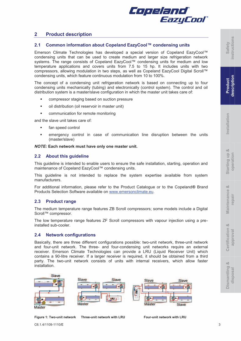
2.4 Network configurations
Basically, there are three different configurations possible: two-unit network, three-unit network and four-unit network. The three- and four-condensing unit networks require an external receiver. Emerson Climate Technologies can provide a LRU (Liquid Receiver Unit) which contains a 90-litre receiver. If a larger receiver is required, it should be obtained from a third party. The two-unit network consists of units with internal receivers, which allow faster installation.
Figure 1: Two-unit network Three-unit network with LRU Four-unit network with LRU
Safe
ty
instr
ucti
on
s
Pro
du
ct
descri
pti
on
Insta
llati
on
S
tart
ing
up
&
op
era
tio
n
Main
ten
an
ce
&
rep
air
Cert
ific
ati
on
&
ap
pro
val
Dis
man
tlin
g &
dis
po
sal
4 C6.1.4/1109-1110/E
2.5 Product nameplate
The condensing unit nameplate shows model designation and serial number.
The compressor has its own nameplate with all electrical characteristics.
2.6 Nomenclature
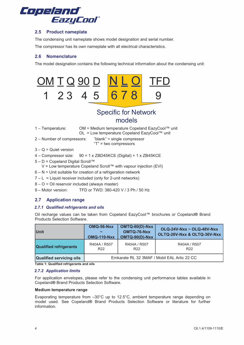
The model designation contains the following technical information about the condensing unit:
1 – Temperature: OM = Medium temperature Copeland EazyCool™ unit OL = Low temperature Copeland EazyCool™ unit
2 – Number of compressors: “blank” = single compressor “T” = two compressors
3 – Q = Quiet version
4 – Compressor size: 90 = 1 x ZBD45KCE (Digital) + 1 x ZB45KCE
5 – D = Copeland Digital Scroll™ V = Low temperature Copeland Scroll™ with vapour injection (EVI)
6 – N = Unit suitable for creation of a refrigeration network
7 – L = Liquid receiver included (only for 2-unit networks)
8 – O = Oil reservoir included (always master)
9 – Motor version: TFD or TWD: 380-420 V / 3 Ph / 50 Hz
2.7 Application range
2.7.1 Qualified refrigerants and oils
Oil recharge values can be taken from Copeland EazyCool™ brochures or Copeland® Brand Products Selection Software.
Unit
OMQ-56-Nxx
~
OMQ-110-Nxx
OMTQ-60(D)-Nxx
OMTQ-76-Nxx
OMTQ-90(D)-Nxx
OLQ-24V-Nxx ~ OLQ-48V-Nxx
OLTQ-26V-Nxx & OLTQ-36V-Nxx
Qualified refrigerantsR404A / R507
R22
R404A / R507
R22
R404A / R507
R22
Qualified servicing oils Emkarate RL 32 3MAF / Mobil EAL Artic 22 CC
Table 1: Qualified refrigerants and oils
2.7.2 Application limits
For application envelopes, please refer to the condensing unit performance tables available in Copeland® Brand Products Selection Software.
Medium temperature range
Evaporating temperature from –30°C up to 12.5°C, ambient temperature range depending on model used. See Copeland® Brand Products Selection Software or literature for further information.
OM T Q 90 D N L O TFD
1 2 3 4 5 6 7 8 9
Specific for Network
models
C6.1.4/1109-1110/E 5
Low temperature range
Evaporating temperature from –40°C up to 7°C, ambient temperature range depending on model used. See Copeland® Brand Products Selection Software or literature for further information.
2.8 Main component description
2.8.1 Compressor
Unit model Compressor model Unit model Compressor model
OMQ-56-Nxx-TWD ZB56KCE-TWD-551 OLQ-24V-Nxx-TWD ZF24KVE-TWD-551
OMQ-75-Nxx-TWD ZB75KCE-TWD-551 OLQ-33V-Nxx-TWD ZF33KVE-TWD-551
OMQ-92-Nxx-TWD ZB92KCE-TWD-551 OLQ-40V-Nxx-TWD ZF40KVE-TWD-551
OMQ-110-Nxx-TWD ZB11MCE-TWD-551 OLQ-48V-Nxx-TWD ZF48KVE-TWD-551
OMTQ-60-Nxx-TFD 2 x ZB30KCE-TFD-551 OLTQ-26V-Nxx-TFD 2 x ZF13KVE-TFD-556
OMTQ-60D-Nxx-TFD (*) 1 X ZBD30KCE-TFD-551
1 x ZB30KCE-TFD-551
OMTQ-76-Nxx-TFD 2 x ZB38KCE-TFD-551
OMTQ-90-Nxx-TFD 2 x ZB45KCE-TFD-551 OLTQ-36V-Nxx-TFD 2 x ZF18KVE-TFD-556
OMTQ-90D-Nxx-TFD (*) 1 X ZBD45KCE-TFD-551
1 x ZB45KCE-TFD-551
(*) Digital Scroll™ compressor available
in Master version only (NLO & NO)
(*) Digital Scroll™ compressor available
in Master version only (NLO & NO)
Low temperatureMedium temperature
Two-compressor unit
Single compressor unit
Table 2: Compressor type used in Copeland EazyCool™ condensing units for refrigeration networks
2.8.2 Sound blanket
The OM(T)Q and OL(T)Q units include one or two compressors, equipped with a sound jacket. The sound jacket developed by Emerson Climate Technologies has no impact on the performance of the compressor.
The design consists of a top cap cover and compressor shell cover with adjustable Velcro system. It has good characteristics in case of fire and is resistant to:
§ mineral and polyolester oil
§ refrigerants R22 / R404A
§ temperature up to 150°C
§ water
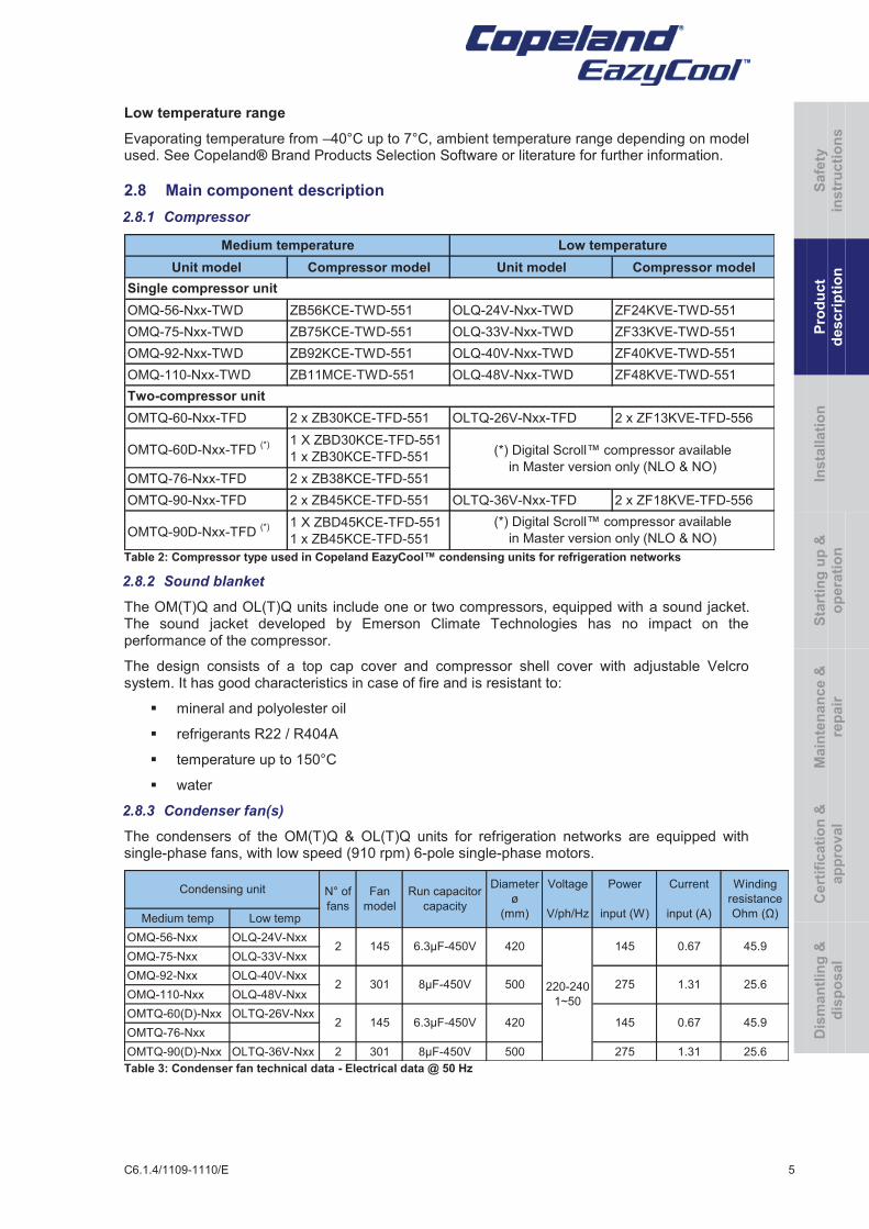
2.8.3 Condenser fan(s)
The condensers of the OM(T)Q & OL(T)Q units for refrigeration networks are equipped with single-phase fans, with low speed (910 rpm) 6-pole single-phase motors.
Medium temp Low temp
OMQ-56-Nxx OLQ-24V-Nxx
OMQ-75-Nxx OLQ-33V-Nxx
OMQ-92-Nxx OLQ-40V-Nxx
OMQ-110-Nxx OLQ-48V-Nxx
OMTQ-60(D)-Nxx OLTQ-26V-Nxx
OMTQ-76-Nxx
OMTQ-90(D)-Nxx OLTQ-36V-Nxx 2 301 8µF-450V 500 275 1.31 25.6
Winding
resistance
Ohm (Ω)
45.9
25.6
45.9
1.31
0.67
Current
input (A)
0.67
Power
input (W)
145
275
145
Voltage
V/ph/Hz
220-240
1~50
Diameter
ø
(mm)
420
500
Run capacitor
capacity
6.3µF-450V
8µF-450V
6.3µF-450V
Condensing unit N° of
fans
2
2
Fan
model
145
301
1452 420
Table 3: Condenser fan technical data - Electrical data @ 50 Hz
Safe
ty
instr
ucti
on
s
Pro
du
ct
descri
pti
on
Insta
llati
on
S
tart
ing
up
&
op
era
tio
n
Main
ten
an
ce
&
rep
air
Cert
ific
ati
on
&
ap
pro
val
Dis
man
tlin
g &
dis
po
sal
6 C6.1.4/1109-1110/E
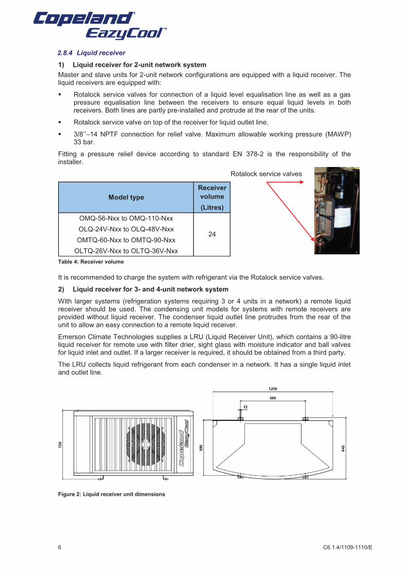
2.8.4 Liquid receiver
1) Liquid receiver for 2-unit network system
Master and slave units for 2-unit network configurations are equipped with a liquid receiver. The liquid receivers are equipped with:
§ Rotalock service valves for connection of a liquid level equalisation line as well as a gas pressure equalisation line between the receivers to ensure equal liquid levels in both receivers. Both lines are partly pre-installed and protrude at the rear of the units.
§ Rotalock service valve on top of the receiver for liquid outlet line.
§ 3/8’’–14 NPTF connection for relief valve. Maximum allowable working pressure (MAWP) 33 bar.
Fitting a pressure relief device according to standard EN 378-2 is the responsibility of the installer.
Rotalock service valves
Receiver
volume
(Litres)
OMQ-56-Nxx to OMQ-110-Nxx
OLQ-24V-Nxx to OLQ-48V-Nxx
OMTQ-60-Nxx to OMTQ-90-Nxx
OLTQ-26V-Nxx to OLTQ-36V-Nxx
Model type
24
Table 4: Receiver volume
It is recommended to charge the system with refrigerant via the Rotalock service valves.
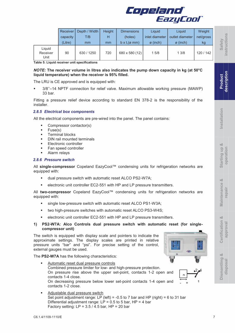
2) Liquid receiver for 3- and 4-unit network system
With larger systems (refrigeration systems requiring 3 or 4 units in a network) a remote liquid receiver should be used. The condensing unit models for systems with remote receivers are provided without liquid receiver. The condenser liquid outlet line protrudes from the rear of the unit to allow an easy connection to a remote liquid receiver.
Emerson Climate Technologies supplies a LRU (Liquid Receiver Unit), which contains a 90-litre liquid receiver for remote use with filter drier, sight glass with moisture indicator and ball valves for liquid inlet and outlet. If a larger receiver is required, it should be obtained from a third party.
The LRU collects liquid refrigerant from each condenser in a network. It has a single liquid inlet and outlet line.
Figure 2: Liquid receiver unit dimensions
C6.1.4/1109-1110/E 7
Receiver Depth / Width Height Dimensions Liquid Liquid Weight
capacity T/B H (holes) inlet diameter outlet diameter net/gross
(Litre) mm mm b x t,(ø mm) ø (inch) ø (inch) kg
Liquid
Receiver
Unit
90 630 / 1250 720 680 x 580 (12) 1 5/8 1 3/8 120 / 142
Table 5: Liquid receiver unit specifications
NOTE: The receiver volume in litres also indicates the pump down capacity in kg (at 50°C liquid temperature) when the receiver is 95% filled.
The LRU is CE approved and is equipped with:
§ 3/8’’–14 NPTF connection for relief valve. Maximum allowable working pressure (MAWP) 33 bar.
Fitting a pressure relief device according to standard EN 378-2 is the responsibility of the installer.
2.8.5 Electrical box components
All the electrical components are pre-wired into the panel. The panel contains:
§ Compressor contactor(s) § Fuse(s) § Terminal blocks § DIN rail mounted terminals § Electronic controller § Fan speed controller § Alarm relays
2.8.6 Pressure switch
All single-compressor Copeland EazyCool™ condensing units for refrigeration networks are equipped with:
§ dual pressure switch with automatic reset ALCO PS2-W7A;
§ electronic unit controller EC2-551 with HP and LP pressure transmitters.
All two-compressor Copeland EazyCool™ condensing units for refrigeration networks are equipped with:
§ single low-pressure switch with automatic reset ALCO PS1-W3A;
§ two high-pressure switches with automatic reset ALCO PS3-W4S;
§ electronic unit controller EC2-551 with HP and LP pressure transmitters.
1) PS2-W7A: Alco Controls dual pressure switch with automatic reset (for single-compressor unit)
The switch is equipped with display scale and pointers to indicate the approximate settings. The display scales are printed in relative pressure units “bar” and “psi”. For precise setting of the control, external gauges must be used.
The PS2-W7A has the following characteristics:
§ Automatic reset dual pressure controls Combined pressure limiter for low- and high-pressure protection. On pressure rise above the upper set-point, contacts 1-2 open and contacts 1-4 close. On decreasing pressure below lower set-point contacts 1-4 open and contacts 1-2 close.
§ Adjustable dual pressure switch Set point adjustment range: LP (left) = -0.5 to 7 bar and HP (right) = 6 to 31 bar Differential adjustment range: LP = 0.5 to 5 bar, HP = 4 bar Factory setting: LP = 3.5 / 4.5 bar, HP = 20 bar
2 4
1
p
- +
Safe
ty
instr
ucti
on
s
Pro
du
ct
descri
pti
on
Insta
llati
on
S
tart
ing
up
&
op
era
tio
n
Main
ten
an
ce
&
rep
air
Cert
ific
ati
on
&
ap
pro
val
Dis
man
tlin
g &
dis
po
sal
8 C6.1.4/1109-1110/E
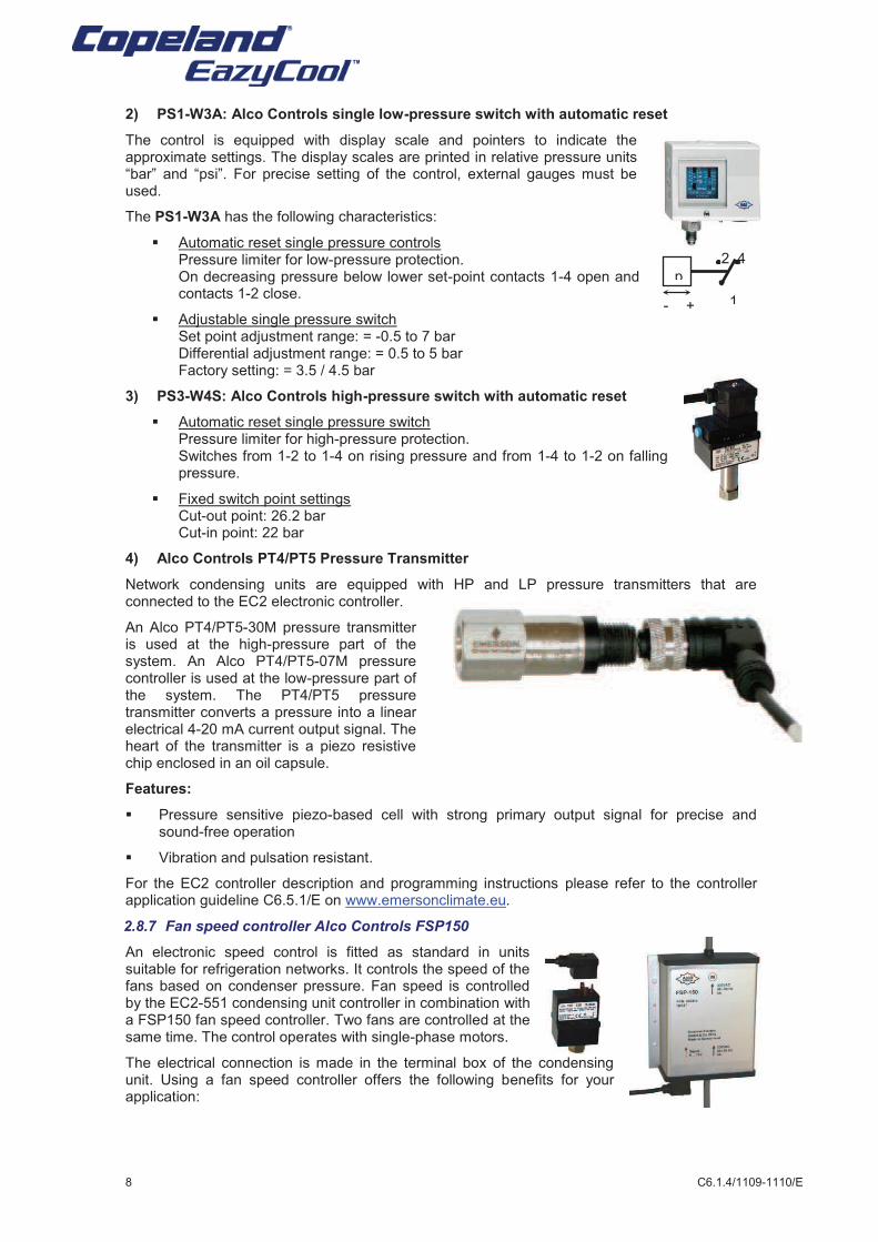
2) PS1-W3A: Alco Controls single low-pressure switch with automatic reset
The control is equipped with display scale and pointers to indicate the approximate settings. The display scales are printed in relative pressure units “bar” and “psi”. For precise setting of the control, external gauges must be used.
The PS1-W3A has the following characteristics:
§ Automatic reset single pressure controls Pressure limiter for low-pressure protection. On decreasing pressure below lower set-point contacts 1-4 open and contacts 1-2 close.
§ Adjustable single pressure switch Set point adjustment range: = -0.5 to 7 bar Differential adjustment range: = 0.5 to 5 bar Factory setting: = 3.5 / 4.5 bar
3) PS3-W4S: Alco Controls high-pressure switch with automatic reset
§ Automatic reset single pressure switch Pressure limiter for high-pressure protection. Switches from 1-2 to 1-4 on rising pressure and from 1-4 to 1-2 on falling pressure.
§ Fixed switch point settings Cut-out point: 26.2 bar Cut-in point: 22 bar
4) Alco Controls PT4/PT5 Pressure Transmitter
Network condensing units are equipped with HP and LP pressure transmitters that are connected to the EC2 electronic controller.
An Alco PT4/PT5-30M pressure transmitter is used at the high-pressure part of the system. An Alco PT4/PT5-07M pressure controller is used at the low-pressure part of the system. The PT4/PT5 pressure transmitter converts a pressure into a linear electrical 4-20 mA current output signal. The heart of the transmitter is a piezo resistive chip enclosed in an oil capsule.
Features:
§ Pressure sensitive piezo-based cell with strong primary output signal for precise and sound-free operation
§ Vibration and pulsation resistant.
For the EC2 controller description and programming instructions please refer to the controller application guideline C6.5.1/E on www.emersonclimate.eu.
2.8.7 Fan speed controller Alco Controls FSP150
An electronic speed control is fitted as standard in units suitable for refrigeration networks. It controls the speed of the fans based on condenser pressure. Fan speed is controlled by the EC2-551 condensing unit controller in combination with a FSP150 fan speed controller. Two fans are controlled at the same time. The control operates with single-phase motors.
The electrical connection is made in the terminal box of the condensing unit. Using a fan speed controller offers the following benefits for your application:
2 4
1
p
- +
C6.1.4/1109-1110/E 9
§ The head pressure can be kept high enough to ensure proper operation of the expansion valve, hence sufficient mass flow through the expansion valve to feed the evaporator. This maintains the required cooling capacity and avoids a drop of evaporator temperature.
§ The sound level of fan motors can be kept at a minimum by avoiding the permanent on/off cycling of the fan motor.
The Alco Controls fan speed control can be delivered with the Copeland® Brand Products units or as a separate accessory.
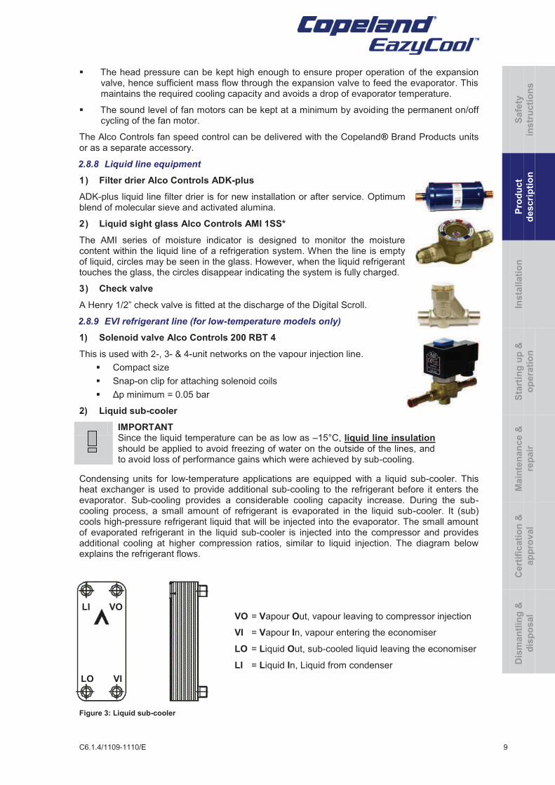
2.8.8 Liquid line equipment
1) Filter drier Alco Controls ADK-plus
ADK-plus liquid line filter drier is for new installation or after service. Optimum blend of molecular sieve and activated alumina.
2) Liquid sight glass Alco Controls AMI 1SS*
The AMI series of moisture indicator is designed to monitor the moisture content within the liquid line of a refrigeration system. When the line is empty of liquid, circles may be seen in the glass. However, when the liquid refrigerant touches the glass, the circles disappear indicating the system is fully charged.
3) Check valve
A Henry 1/2” check valve is fitted at the discharge of the Digital Scroll.
2.8.9 EVI refrigerant line (for low-temperature models only)
1) Solenoid valve Alco Controls 200 RBT 4
This is used with 2-, 3- & 4-unit networks on the vapour injection line.
§ Compact size
§ Snap-on clip for attaching solenoid coils
§ Δp minimum = 0.05 bar
2) Liquid sub-cooler
IMPORTANT Since the liquid temperature can be as low as –15°C, liquid line insulation should be applied to avoid freezing of water on the outside of the lines, and to avoid loss of performance gains which were achieved by sub-cooling.
Condensing units for low-temperature applications are equipped with a liquid sub-cooler. This heat exchanger is used to provide additional sub-cooling to the refrigerant before it enters the evaporator. Sub-cooling provides a considerable cooling capacity increase. During the sub-cooling process, a small amount of refrigerant is evaporated in the liquid sub-cooler. It (sub) cools high-pressure refrigerant liquid that will be injected into the evaporator. The small amount of evaporated refrigerant in the liquid sub-cooler is injected into the compressor and provides additional cooling at higher compression ratios, similar to liquid injection. The diagram below explains the refrigerant flows.
VO = Vapour Out, vapour leaving to compressor injection
VI = Vapour In, vapour entering the economiser
LO = Liquid Out, sub-cooled liquid leaving the economiser
LI = Liquid In, Liquid from condenser
Figure 3: Liquid sub-cooler
VO
LO
LI
VI
Safe
ty
instr
ucti
on
s
Pro
du
ct
descri
pti
on
Insta
llati
on
S
tart
ing
up
&
op
era
tio
n
Main
ten
an
ce
&
rep
air
Cert
ific
ati
on
&
ap
pro
val
Dis
man
tlin
g &
dis
po
sal
10 C6.1.4/1109-1110/E
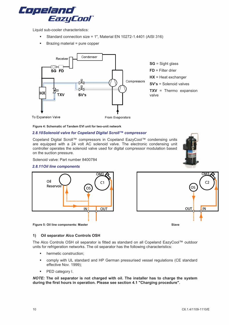
Liquid sub-cooler characteristics:
§ Standard connection size = 1", Material EN 10272-1.4401 (AISI 316)
§ Brazing material = pure copper
SG = Sight glass
FD = Filter drier
HX = Heat exchanger
SV’s = Solenoid valves
TXV = Thermo expansion valve
Figure 4: Schematic of Tandem EVI unit for two-unit network
2.8.10 Solenoid valve for Copeland Digital Scroll™ compressor
Copeland Digital Scroll™ compressors in Copeland EazyCool™ condensing units are equipped with a 24 volt AC solenoid valve. The electronic condensing unit controller operates the solenoid valve used for digital compressor modulation based on the suction pressure.
Solenoid valve: Part number 8400784
2.8.11 Oil line components
Figure 5: Oil line components: Master Slave
1) Oil separator Alco Controls OSH
The Alco Controls OSH oil separator is fitted as standard on all Copeland EazyCool™ outdoor units for refrigeration networks. The oil separator has the following characteristics:
§ hermetic construction;
§ comply with UL standard and HP German pressurised vessel regulations (CE standard effective Nov. 1999);
§ PED category I.
NOTE: The oil separator is not charged with oil. The installer has to charge the system during the first hours in operation. Please see section 4.1 "Charging procedure".
C6.1.4/1109-1110/E 11
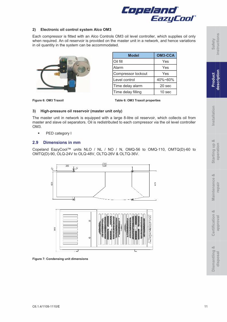
2) Electronic oil control system Alco OM3
Each compressor is fitted with an Alco Controls OM3 oil level controller, which supplies oil only when required. An oil reservoir is provided on the master unit in a network, and hence variations in oil quantity in the system can be accommodated.
Figure 6: OM3 Traxoil Table 6: OM3 Traxoil properties
3) High-pressure oil reservoir (master unit only)
The master unit in network is equipped with a large 8-litre oil reservoir, which collects oil from master and slave oil separators. Oil is redistributed to each compressor via the oil level controller OM3.
§ PED category I
2.9 Dimensions in mm
Copeland EazyCool™ units NLO / NL / NO / N, OMQ-56 to OMQ-110, OMTQ(D)-60 to OMTQ(D)-90, OLQ-24V to OLQ-48V, OLTQ-26V & OLTQ-36V.
Figure 7: Condensing unit dimensions
Model OM3-CCA
Oil fill Yes
Alarm Yes
Compressor lockout Yes
Level control 40%~60%
Time delay alarm 20 sec
Time delay filling 10 sec
Safe
ty
instr
ucti
on
s
Pro
du
ct
descri
pti
on
Insta
llati
on
S
tart
ing
up
&
op
era
tio
n
Main
ten
an
ce
&
rep
air
Cert
ific
ati
on
&
ap
pro
val
Dis
man
tlin
g &
dis
po
sal
12 C6.1.4/1109-1110/E
3 Installation
WARNING
High pressure! Injury to skin and eyes possible! Be careful when opening connections on a pressurized item.
Copeland EazyCool™ condensing units are delivered with a holding charge of neutral gas.
The condensing unit should be located in such a place as to prevent any dirt, plastic bag, leaves or papers from covering the condenser and its fins.
The unit must be installed without restricting the airflow.
A clogged condenser will increase the condensing temperature, thus reduce the cooling capacity, and lead to a high-pressure switch tripping. Clean the condenser fins on a regular basis.
3.1 Condensing unit handling
3.1.1 Transport and storage
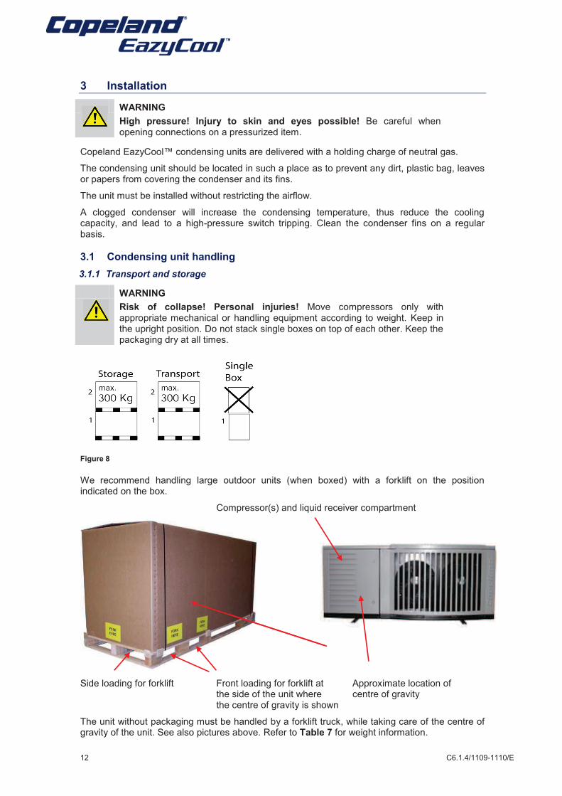
WARNING
Risk of collapse! Personal injuries! Move compressors only with appropriate mechanical or handling equipment according to weight. Keep in the upright position. Do not stack single boxes on top of each other. Keep the packaging dry at all times.
Figure 8
We recommend handling large outdoor units (when boxed) with a forklift on the position indicated on the box.
Compressor(s) and liquid receiver compartment
Side loading for forklift Front loading for forklift at Approximate location of the side of the unit where centre of gravity
the centre of gravity is shown
The unit without packaging must be handled by a forklift truck, while taking care of the centre of gravity of the unit. See also pictures above. Refer to Table 7 for weight information.
C6.1.4/1109-1110/E 13
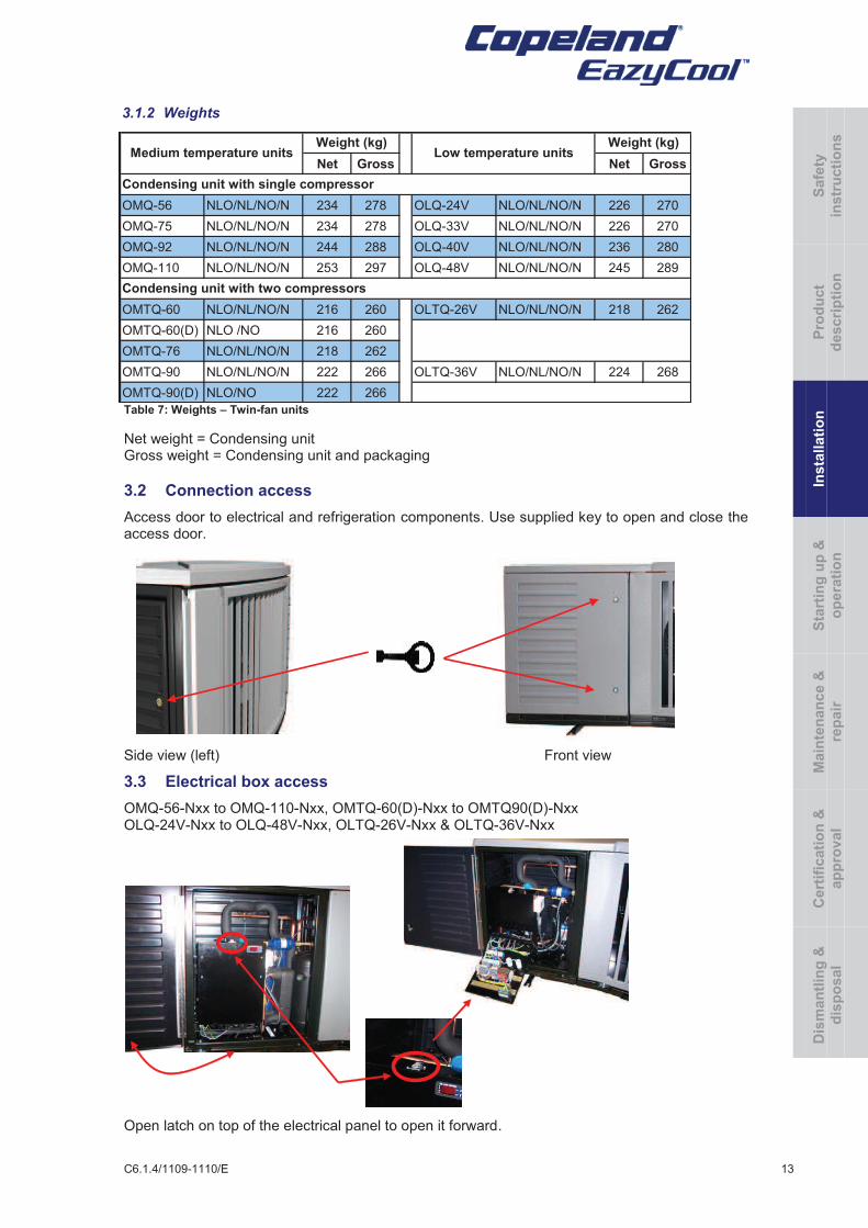
3.1.2 Weights
Table 7: Weights – Twin-fan units
Net weight = Condensing unit Gross weight = Condensing unit and packaging
3.2 Connection access
Access door to electrical and refrigeration components. Use supplied key to open and close the access door.
Side view (left) Front view
3.3 Electrical box access
OMQ-56-Nxx to OMQ-110-Nxx, OMTQ-60(D)-Nxx to OMTQ90(D)-Nxx OLQ-24V-Nxx to OLQ-48V-Nxx, OLTQ-26V-Nxx & OLTQ-36V-Nxx
Open latch on top of the electrical panel to open it forward.
Net Gross Net Gross
OMQ-56 NLO/NL/NO/N 234 278 OLQ-24V NLO/NL/NO/N 226 270
OMQ-75 NLO/NL/NO/N 234 278 OLQ-33V NLO/NL/NO/N 226 270
OMQ-92 NLO/NL/NO/N 244 288 OLQ-40V NLO/NL/NO/N 236 280
OMQ-110 NLO/NL/NO/N 253 297 OLQ-48V NLO/NL/NO/N 245 289
OMTQ-60 NLO/NL/NO/N 216 260 OLTQ-26V NLO/NL/NO/N 218 262
OMTQ-60(D) NLO /NO 216 260
OMTQ-76 NLO/NL/NO/N 218 262
OMTQ-90 NLO/NL/NO/N 222 266 OLTQ-36V NLO/NL/NO/N 224 268
OMTQ-90(D) NLO/NO 222 266
Condensing unit with single compressor
Condensing unit with two compressors
Weight (kg) Weight (kg)Low temperature unitsMedium temperature units
Safe
ty
instr
ucti
on
s
Pro
du
ct
descri
pti
on
Insta
llati
on
S
tart
ing
up
&
op
era
tio
n
Main
ten
an
ce &
rep
air
Cert
ific
ati
on
&
ap
pro
val
Dis
man
tlin
g &
dis
po
sal
14 C6.1.4/1109-1110/E
3.4 Electrical connection
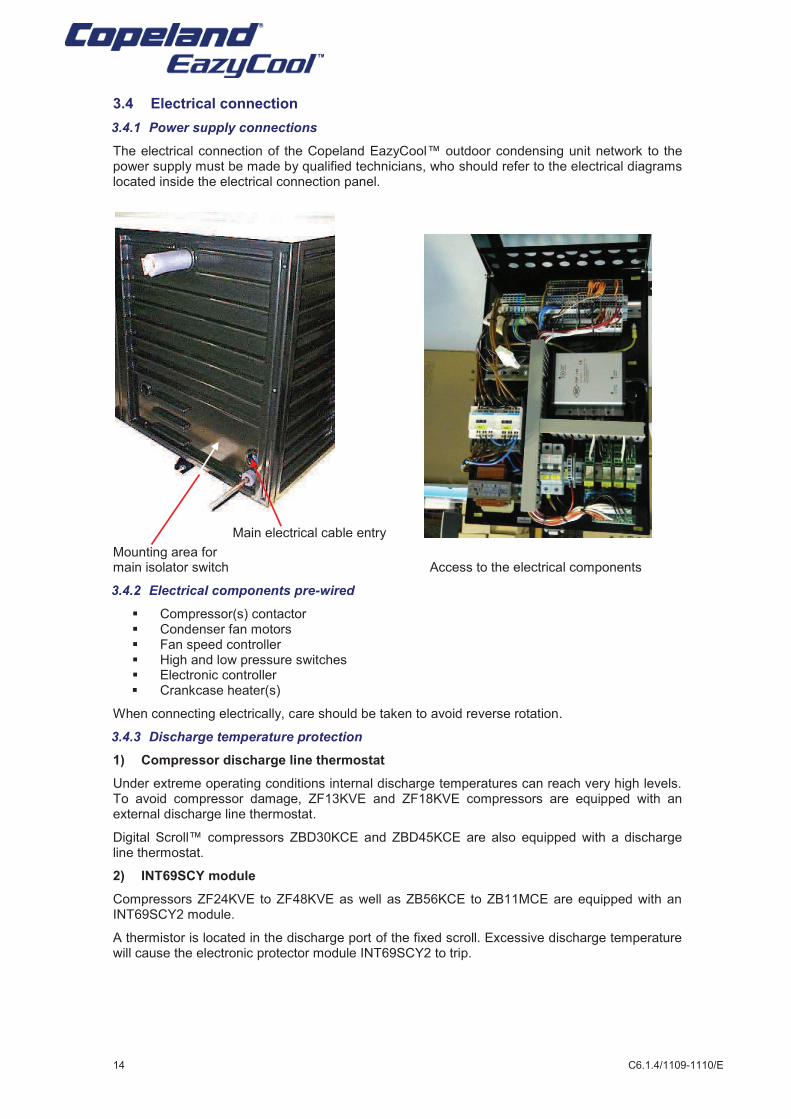
3.4.1 Power supply connections
The electrical connection of the Copeland EazyCool™ outdoor condensing unit network to the power supply must be made by qualified technicians, who should refer to the electrical diagrams located inside the electrical connection panel.
Main electrical cable entry
Mounting area for main isolator switch Access to the electrical components
3.4.2 Electrical components pre-wired
§ Compressor(s) contactor § Condenser fan motors § Fan speed controller § High and low pressure switches § Electronic controller § Crankcase heater(s)
When connecting electrically, care should be taken to avoid reverse rotation.
3.4.3 Discharge temperature protection
1) Compressor discharge line thermostat
Under extreme operating conditions internal discharge temperatures can reach very high levels. To avoid compressor damage, ZF13KVE and ZF18KVE compressors are equipped with an external discharge line thermostat.
Digital Scroll™ compressors ZBD30KCE and ZBD45KCE are also equipped with a discharge line thermostat.
2) INT69SCY module
Compressors ZF24KVE to ZF48KVE as well as ZB56KCE to ZB11MCE are equipped with an INT69SCY2 module.
A thermistor is located in the discharge port of the fixed scroll. Excessive discharge temperature will cause the electronic protector module INT69SCY2 to trip.

C6.1.4/1109-1110/E 15
3.4.4 Electrical protection standard (protection class)
§ Scroll compressors up to ZB45/ZF18 are IP21 according to IEC 34. All larger compressors are IP54.
§ Fan is IP54 according to IEC 34. § HP-LP and HP safety pressure switches (Alco PS2 and PS1) are IP44 according to IEC
529/EN 60529. § PS3 switch with cable assy is IP65 according to EN 175301-803/IEC 529. § Fan speed controller FSP150 is IP67 according to IEC 529/EN 60529. § Solenoid valve coils: IP65 according to DIN 43650. § EC2-551 is IP65 (frontal protection with gasket). § Electrical panel is IP54
3.4.5 Condensing unit electrical data
Table 8: Electrical data
PFJ: 220-240V/1~/50 Hz TFD: 380-420V/3~/50 Hz TWD: 380-420V/3~/50 Hz
Single compressor
condensing unit
Max. operating
Current
(compressor)
Locked Rotor
Current
(compressor)
Fan
Model
Max. fan
Current 3)
Max. operating
Current (Unit)
A A A A
Medium Temperature TWD TWD 230V / 1~/50Hz TWD
OMQ-56-NLO/NL/NO/N 15.4 99 2 x 145 0.81 17.02
OMQ-75-NLO/NL/NO/N 21.7 127 2 x 145 0.81 23.32
OMQ-92-NLO/NL/NO/N 25.1 167 2 x 301 1.56 28.22
OMQ-110-NLO/NL/NO/N 29.2 198 2 x 301 1.56 32.32
Low Temperature TWD TWD 230V / 1~/50Hz TWD
OLQ-24V-NLO/NL/NO/N 16.1 2 x 145 0.81 17.72
OLQ-33V-NLO/NL/NO/N 22.3 2 x 145 0.81 23.92
OLQ-40V-NLO/NL/NO/N 25.1 2 x 301 1.56 28.22
OLQ-48V-NLO/NL/NO/N 30.6 2 x 301 1.56 33.72
Two compressor
condensing unit
Max. operating
Current
(compressor) 1)
Locked Rotor
Current
(compressor) 1)
Fan
Model
Max. fan
Current 3)
Max. operating
Current (Unit)
A A A A
Medium Temperature TFD TFD 230V / 1~/50Hz TFD
OMTQ-60-NLO/NL/NO/N 10.3 49 2 x 145 0.81 22.22
OMTQ-60(D)-NLO /NO 7.9 / 10.3 2) 52 2 x 145 0.81 19.82
OMTQ-76-NLO/NL/NO/N 12.8 66 2 x 145 0.81 27.22
OMTQ-90-NLO/NL/NO/N 13.1 74 2 x 301 1.56 29.32
OMTQ-90(D)-NLO/NO 11.4 / 13.1 2) 74 2 x 301 1.56 27.62
Low Temperature TFD TFD 230V / 1~/50Hz TFD
OLTQ-26V-NLO/NL/NO/N 8 52 2 x 145 0.81 17.62
OLTQ-36V-NLO/NL/NO/N 12 74 2 x 301 1.56 27.12
1) Data for one compressor
2) Digital Scroll
TM / Standard Compressor
3) Data for one fan motor
Safe
ty
instr
ucti
on
s
Pro
du
ct
descri
pti
on
Insta
llati
on
S
tart
ing
up
&
op
era
tio
n
Main
ten
an
ce &
rep
air
Cert
ific
ati
on
&
ap
pro
val
Dis
man
tlin
g &
dis
po
sal
16 C6.1.4/1109-1110/E
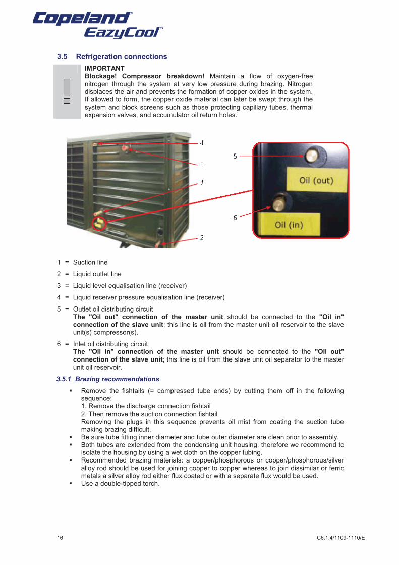
3.5 Refrigeration connections
IMPORTANT Blockage! Compressor breakdown! Maintain a flow of oxygen-free nitrogen through the system at very low pressure during brazing. Nitrogen displaces the air and prevents the formation of copper oxides in the system. If allowed to form, the copper oxide material can later be swept through the system and block screens such as those protecting capillary tubes, thermal expansion valves, and accumulator oil return holes.
1 = Suction line
2 = Liquid outlet line
3 = Liquid level equalisation line (receiver)
4 = Liquid receiver pressure equalisation line (receiver)
5 = Outlet oil distributing circuit The "Oil out" connection of the master unit should be connected to the "Oil in" connection of the slave unit; this line is oil from the master unit oil reservoir to the slave unit(s) compressor(s).
6 = Inlet oil distributing circuit The "Oil in" connection of the master unit should be connected to the "Oil out" connection of the slave unit; this line is oil from the slave unit oil separator to the master unit oil reservoir.
3.5.1 Brazing recommendations
§ Remove the fishtails (= compressed tube ends) by cutting them off in the following sequence:
1. Remove the discharge connection fishtail 2. Then remove the suction connection fishtail Removing the plugs in this sequence prevents oil mist from coating the suction tube making brazing difficult. § Be sure tube fitting inner diameter and tube outer diameter are clean prior to assembly. § Both tubes are extended from the condensing unit housing, therefore we recommend to
isolate the housing by using a wet cloth on the copper tubing. § Recommended brazing materials: a copper/phosphorous or copper/phosphorous/silver
alloy rod should be used for joining copper to copper whereas to join dissimilar or ferric metals a silver alloy rod either flux coated or with a separate flux would be used.
§ Use a double-tipped torch.
C6.1.4/1109-1110/E 17
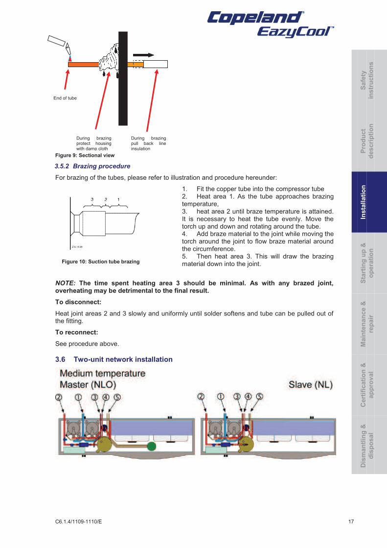
Figure 10: Suction tube brazing
During brazing protect housing with damp cloth
During brazing pull back line insulation
End of tube
Figure 9: Sectional view
3.5.2 Brazing procedure
For brazing of the tubes, please refer to illustration and procedure hereunder:
1. Fit the copper tube into the compressor tube 2. Heat area 1. As the tube approaches brazing temperature, 3. heat area 2 until braze temperature is attained. It is necessary to heat the tube evenly. Move the torch up and down and rotating around the tube. 4. Add braze material to the joint while moving the torch around the joint to flow braze material around the circumference. 5. Then heat area 3. This will draw the brazing material down into the joint.
NOTE: The time spent heating area 3 should be minimal. As with any brazed joint, overheating may be detrimental to the final result.
To disconnect:
Heat joint areas 2 and 3 slowly and uniformly until solder softens and tube can be pulled out of the fitting.
To reconnect:
See procedure above.
3.6 Two-unit network installation
Safe
ty
instr
ucti
on
s
Pro
du
ct
descri
pti
on
Insta
llati
on
S
tart
ing
up
&
op
era
tio
n
Main
ten
an
ce &
rep
air
Cert
ific
ati
on
&
ap
pro
val
Dis
man
tlin
g &
dis
po
sal
18 C6.1.4/1109-1110/E
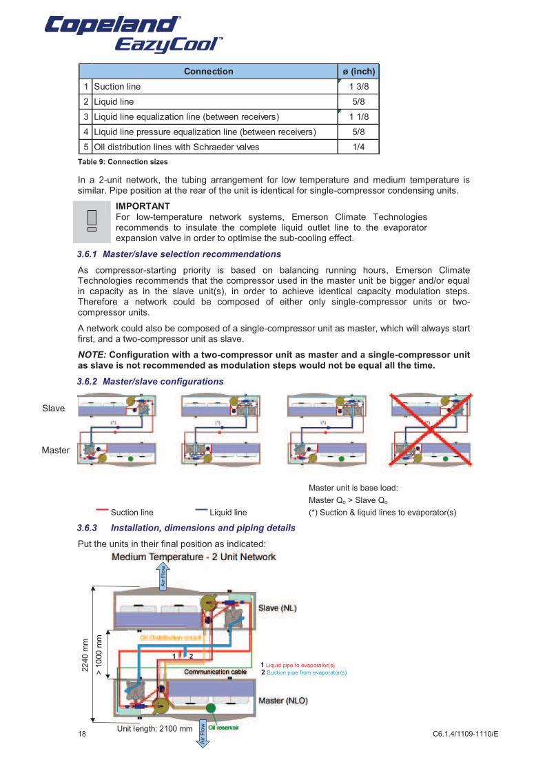
Table 9: Connection sizes
In a 2-unit network, the tubing arrangement for low temperature and medium temperature is similar. Pipe position at the rear of the unit is identical for single-compressor condensing units.
IMPORTANT For low-temperature network systems, Emerson Climate Technologies recommends to insulate the complete liquid outlet line to the evaporator expansion valve in order to optimise the sub-cooling effect.
3.6.1 Master/slave selection recommendations
As compressor-starting priority is based on balancing running hours, Emerson Climate Technologies recommends that the compressor used in the master unit be bigger and/or equal in capacity as in the slave unit(s), in order to achieve identical capacity modulation steps. Therefore a network could be composed of either only single-compressor units or two-compressor units.
A network could also be composed of a single-compressor unit as master, which will always start first, and a two-compressor unit as slave.
NOTE: Configuration with a two-compressor unit as master and a single-compressor unit as slave is not recommended as modulation steps would not be equal all the time.
3.6.2 Master/slave configurations
Master unit is base load:
Master Qo > Slave Qo
Suction line Liquid line (*) Suction & liquid lines to evaporator(s)
3.6.3 Installation, dimensions and piping details
Put the units in their final position as indicated:
Master
> 1
000 m
m
22
40 m
m
Unit length: 2100 mm
2 Suction pipe from evaporator(s)
1 Liquid pipe to evaporator(s)
Air F
low
Air F
low
1 2
Slave
ø (inch)
1 Suction line 1 3/8
2 Liquid line 5/8
3 Liquid line equalization line (between receivers) 1 1/8
4 Liquid line pressure equalization line (between receivers) 5/8
5 Oil distribution lines with Schraeder valves 1/4
Connection
C6.1.4/1109-1110/E 19
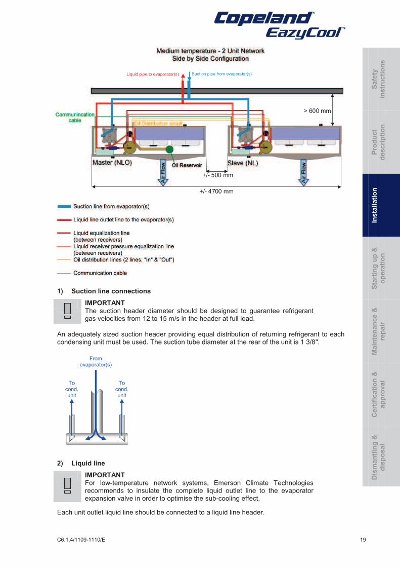
1) Suction line connections
IMPORTANT The suction header diameter should be designed to guarantee refrigerant gas velocities from 12 to 15 m/s in the header at full load.
An adequately sized suction header providing equal distribution of returning refrigerant to each condensing unit must be used. The suction tube diameter at the rear of the unit is 1 3/8".
2) Liquid line
IMPORTANT For low-temperature network systems, Emerson Climate Technologies recommends to insulate the complete liquid outlet line to the evaporator expansion valve in order to optimise the sub-cooling effect.
Each unit outlet liquid line should be connected to a liquid line header.
+/- 500 mm
+/- 4700 mm
> 600 mm
Liquid pipe to evaporator(s) Suction pipe from evaporator(s)
To cond. unit
To cond. unit
From evaporator(s)
Safe
ty
instr
ucti
on
s
Pro
du
ct
descri
pti
on
Insta
llati
on
S
tart
ing
up
&
op
era
tio
n
Main
ten
an
ce &
rep
air
Cert
ific
ati
on
&
ap
pro
val
Dis
man
tlin
g &
dis
po
sal
20 C6.1.4/1109-1110/E
3) Receiver equalization lines
§ Liquid equalization line to be connected between 2 receivers is on the middle bottom of the unit. Copper connection. Diameter 1 1/8".
§ Gas pressure equalization Copper connection. Diameter 5/8".
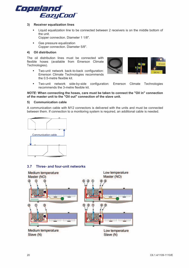
4) Oil distribution
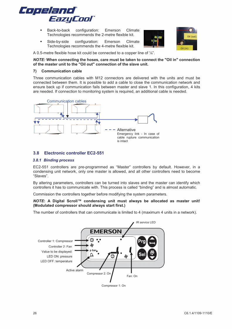
The oil distribution lines must be connected with flexible hoses (available from Emerson Climate Technologies).
§ Two-unit network back-to-back configuration: Emerson Climate Technologies recommends the 0.5-metre flexible kit.
§ Two-unit network side-by-side configuration: Emerson Climate Technologies recommends the 3-metre flexible kit.
NOTE: When connecting the hoses, care must be taken to connect the "Oil in" connection of the master unit to the "Oil out" connection of the slave unit.
5) Communication cable
A communication cable with M12 connectors is delivered with the units and must be connected between them. If connection to a monitoring system is required, an additional cable is needed.
3.7 Three- and four-unit networks
Communication cable
C6.1.4/1109-1110/E 21
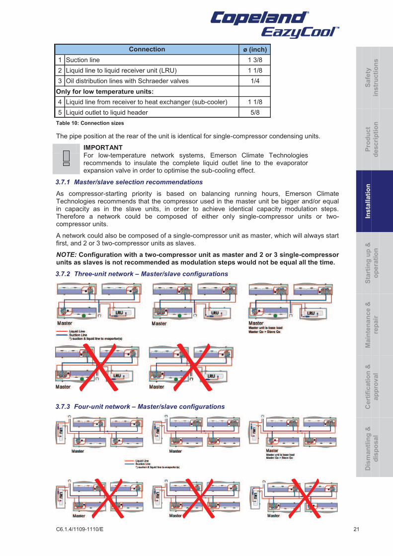
Table 10: Connection sizes
The pipe position at the rear of the unit is identical for single-compressor condensing units.
IMPORTANT For low-temperature network systems, Emerson Climate Technologies recommends to insulate the complete liquid outlet line to the evaporator expansion valve in order to optimise the sub-cooling effect.
3.7.1 Master/slave selection recommendations
As compressor-starting priority is based on balancing running hours, Emerson Climate Technologies recommends that the compressor used in the master unit be bigger and/or equal in capacity as in the slave units, in order to achieve identical capacity modulation steps. Therefore a network could be composed of either only single-compressor units or two-compressor units.
A network could also be composed of a single-compressor unit as master, which will always start first, and 2 or 3 two-compressor units as slaves.
NOTE: Configuration with a two-compressor unit as master and 2 or 3 single-compressor units as slaves is not recommended as modulation steps would not be equal all the time.
3.7.2 Three-unit network – Master/slave configurations
3.7.3 Four-unit network – Master/slave configurations
ø (inch)
1 Suction line 1 3/8
2 Liquid line to liquid receiver unit (LRU) 1 1/8
3 Oil distribution lines with Schraeder valves 1/4
Only for low temperature units:
4 Liquid line from receiver to heat exchanger (sub-cooler) 1 1/8
5 Liquid outlet to liquid header 5/8
Connection
Safe
ty
instr
ucti
on
s
Pro
du
ct
descri
pti
on
Insta
llati
on
S
tart
ing
up
&
op
era
tio
n
Main
ten
an
ce &
rep
air
Cert
ific
ati
on
&
ap
pro
val
Dis
man
tlin
g &
dis
po
sal
22 C6.1.4/1109-1110/E
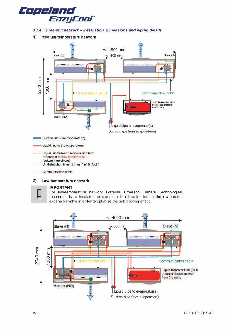
3.7.4 Three-unit network – Installation, dimensions and piping details
1) Medium-temperature network
2) Low-temperature network
IMPORTANT For low-temperature network systems, Emerson Climate Technologies recommends to insulate the complete liquid outlet line to the evaporator expansion valve in order to optimise the sub-cooling effect.
10
00 m
m
22
40 m
m
+/- 600 mm
+/- 4900 mm
Oil distribution circuit
Air F
low
Air F
low
Air F
low
Communication cable
Suction pipe from evaporator(s)
Liquid pipe to evaporator(s)
10
00 m
m
22
40 m
m
+/- 600 mm
+/- 4900 mm
Oil distribution circuit
Air F
low
Air F
low
Air F
low
Communication cable
Suction pipe from evaporator(s)
Liquid pipe to evaporator(s)
C6.1.4/1109-1110/E 23
Low-temperature networks need additional piping between each unit heat exchanger and the receiver, in order to get liquid for vapour injection.
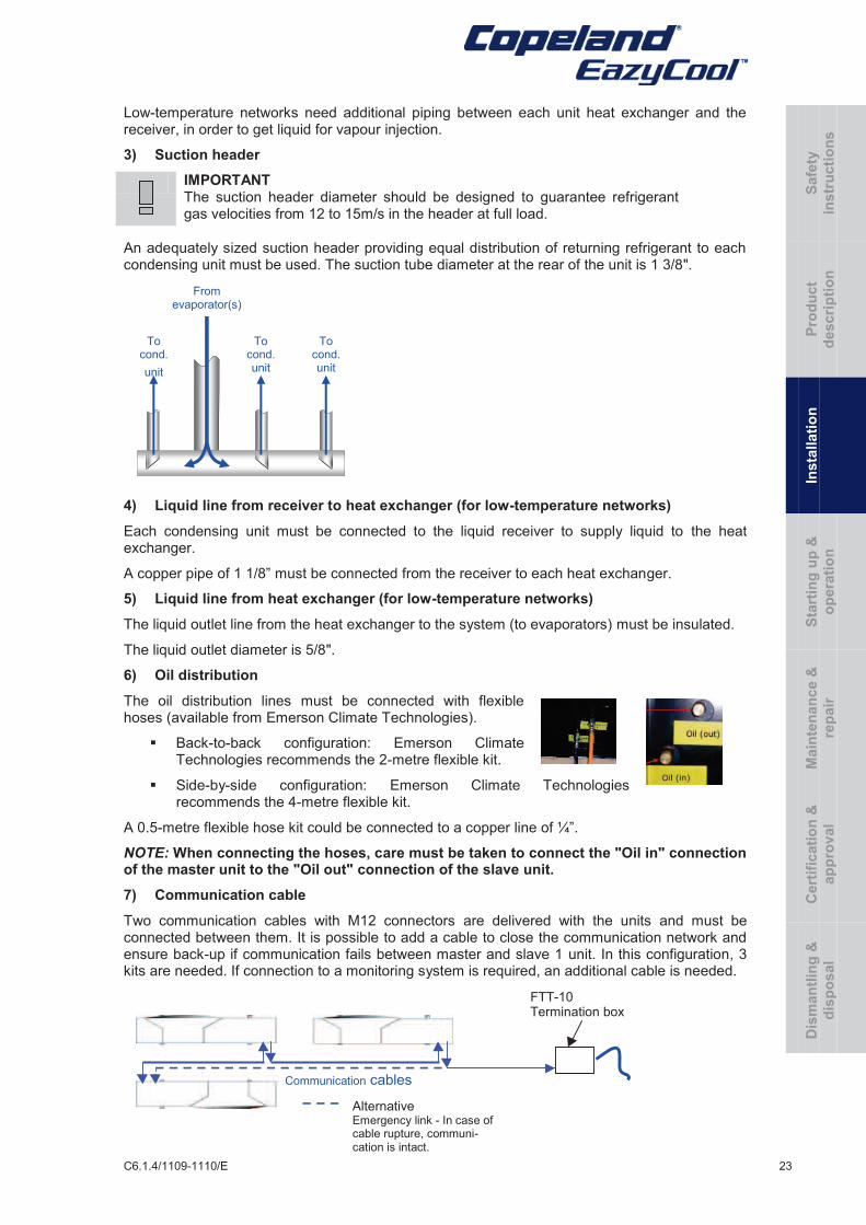
3) Suction header
IMPORTANT The suction header diameter should be designed to guarantee refrigerant gas velocities from 12 to 15m/s in the header at full load.
An adequately sized suction header providing equal distribution of returning refrigerant to each condensing unit must be used. The suction tube diameter at the rear of the unit is 1 3/8".
4) Liquid line from receiver to heat exchanger (for low-temperature networks)
Each condensing unit must be connected to the liquid receiver to supply liquid to the heat exchanger.
A copper pipe of 1 1/8” must be connected from the receiver to each heat exchanger.
5) Liquid line from heat exchanger (for low-temperature networks)
The liquid outlet line from the heat exchanger to the system (to evaporators) must be insulated.
The liquid outlet diameter is 5/8".
6) Oil distribution
The oil distribution lines must be connected with flexible hoses (available from Emerson Climate Technologies).
§ Back-to-back configuration: Emerson Climate Technologies recommends the 2-metre flexible kit.
§ Side-by-side configuration: Emerson Climate Technologies recommends the 4-metre flexible kit.
A 0.5-metre flexible hose kit could be connected to a copper line of ¼”.
NOTE: When connecting the hoses, care must be taken to connect the "Oil in" connection of the master unit to the "Oil out" connection of the slave unit.
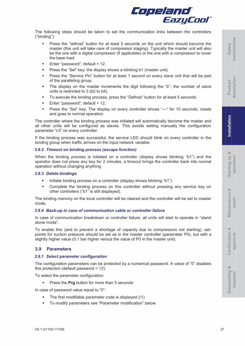
7) Communication cable
Two communication cables with M12 connectors are delivered with the units and must be connected between them. It is possible to add a cable to close the communication network and ensure back-up if communication fails between master and slave 1 unit. In this configuration, 3 kits are needed. If connection to a monitoring system is required, an additional cable is needed.
To cond.
unit
To cond. unit
To cond. unit
From evaporator(s)
Alternative Emergency link - In case of cable rupture, communi-cation is intact.
Communication cables
FTT-10 Termination box
Safe
ty
instr
ucti
on
s
Pro
du
ct
descri
pti
on
Insta
llati
on
S
tart
ing
up
&
op
era
tio
n
Main
ten
an
ce &
rep
air
Cert
ific
ati
on
&
ap
pro
val
Dis
man
tlin
g &
dis
po
sal
24 C6.1.4/1109-1110/E
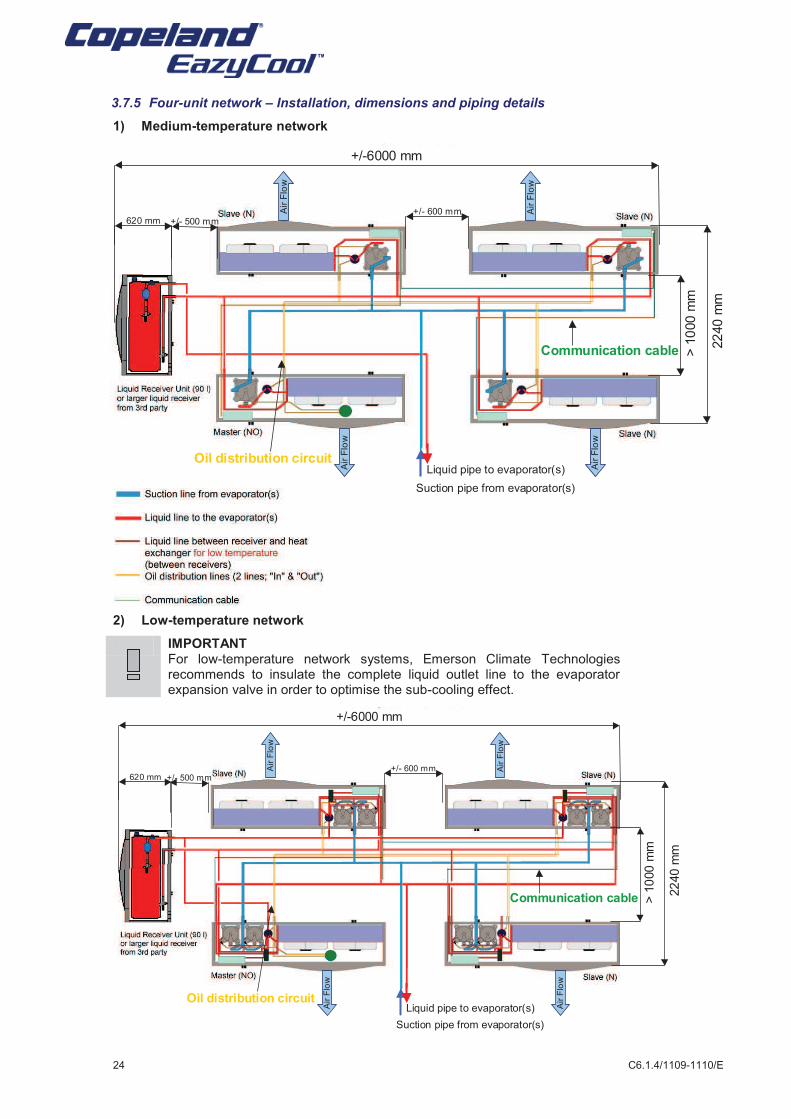
3.7.5 Four-unit network – Installation, dimensions and piping details
1) Medium-temperature network
2) Low-temperature network
IMPORTANT For low-temperature network systems, Emerson Climate Technologies recommends to insulate the complete liquid outlet line to the evaporator expansion valve in order to optimise the sub-cooling effect.
Suction pipe from evaporator(s)
Liquid pipe to evaporator(s)Air F
low
Air F
low
Air F
low
Air F
low
+/- 600 mm
> 1
000 m
m
22
40 m
m
+/- 500 mm620 mm
+/-6000 mm
Oil distribution circuit
Communication cable
Suction pipe from evaporator(s)
Liquid pipe to evaporator(s)Air F
low
Air F
low
Air F
low
Air F
low
+/- 600 mm
> 1
000 m
m
22
40 m
m
+/- 500 mm620 mm
+/-6000 mm
Oil distribution circuit
Communication cable
C6.1.4/1109-1110/E 25
3) Suction header
IMPORTANT The suction header diameter should be designed to guarantee refrigerant gas velocities from 12 to 15m/s in the header at full load.
An adequately sized suction header providing equal distribution of returning refrigerant to each condensing unit must be used. The suction tube diameter at the rear of the unit is 1 3/8".
4) Liquid line from receiver to heat exchanger (for low-temperature networks)
Each condensing unit must be connected to the liquid receiver to supply liquid to the heat exchanger.
A copper pipe of 1 1/8” must be connected from the receiver to each heat exchanger.
5) Liquid line from heat exchanger (for low-temperature networks)
The liquid outlet line from the heat exchanger to the system (to evaporators) must be insulated.
The liquid outlet diameter is 5/8".
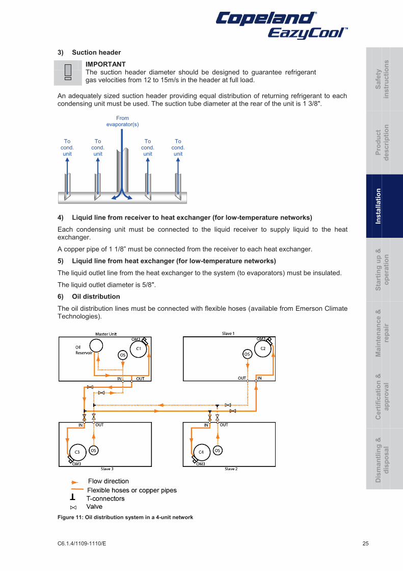
6) Oil distribution
The oil distribution lines must be connected with flexible hoses (available from Emerson Climate Technologies).
Figure 11: Oil distribution system in a 4-unit network
To cond. unit
To cond. unit
To cond. unit
From evaporator(s)
To cond. unit
Safe
ty
instr
ucti
on
s
Pro
du
ct
descri
pti
on
Insta
llati
on
S
tart
ing
up
&
op
era
tio
n
Main
ten
an
ce &
rep
air
Cert
ific
ati
on
&
ap
pro
val
Dis
man
tlin
g &
dis
po
sal
26 C6.1.4/1109-1110/E
§ Back-to-back configuration: Emerson Climate
Technologies recommends the 2-metre flexible kit.
§ Side-by-side configuration: Emerson Climate Technologies recommends the 4-metre flexible kit.
A 0.5-metre flexible hose kit could be connected to a copper line of ¼”.
NOTE: When connecting the hoses, care must be taken to connect the "Oil in" connection of the master unit to the "Oil out" connection of the slave unit.
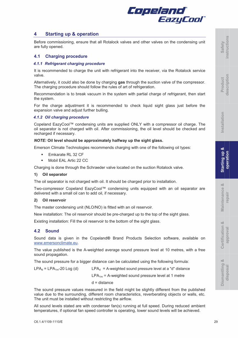
7) Communication cable
Three communication cables with M12 connectors are delivered with the units and must be connected between them. It is possible to add a cable to close the communication network and ensure back up if communication fails between master and slave 1. In this configuration, 4 kits are needed. If connection to monitoring system is required, an additional cable is needed.
3.8 Electronic controller EC2-551
3.8.1 Binding process
EC2-551 controllers are pre-programmed as “Master” controllers by default. However, in a condensing unit network, only one master is allowed, and all other controllers need to become “Slaves”.
By altering parameters, controllers can be turned into slaves and the master can identify which controllers it has to communicate with. This process is called “binding” and is almost automatic.
Commission the controllers together before modifying the system parameters.
NOTE: A Digital Scroll™ condensing unit must always be allocated as master unit! (Modulated compressor should always start first.)
The number of controllers that can communicate is limited to 4 (maximum 4 units in a network).
Alternative Emergency link - In case of cable rupture communication is intact
Communication cables
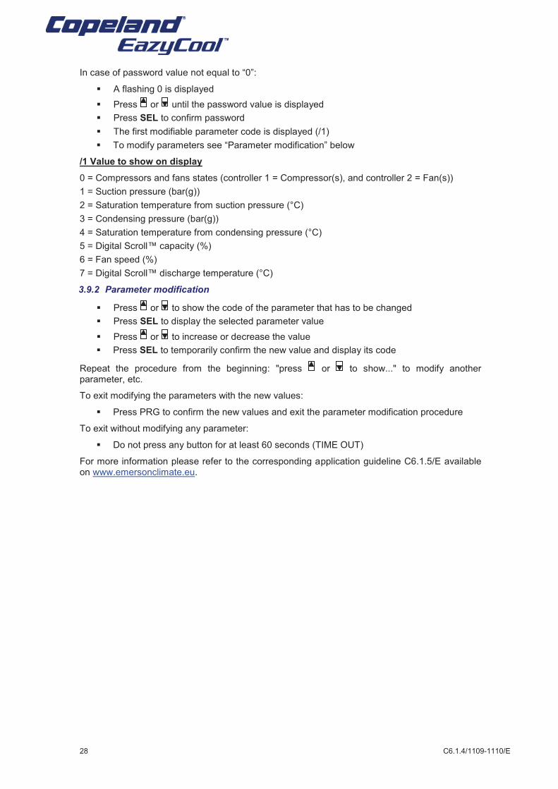
Controller 2: Fan
Value to be displayed:
LED ON: pressure
LED OFF: temperature
Active alarm
)
Compressor 1: On
Fan: On
Compressor 2: On
IR service LED
Controller 1: Compressor
C6.1.4/1109-1110/E 27
The following steps should be taken to set the communication links between the controllers (“binding”):
§ Press the “defrost” button for at least 5 seconds on the unit which should become the master (this unit will take care of compressor staging). Typically the master unit will also be the one with a digital compressor (if applicable) or the one with a compressor to cover the base load.
§ Enter “password”; default = 12.
§ Press the “Sel” key; the display shows a blinking b1 (master unit).
§ Press the “Service Pin” button for at least 1 second on every slave unit that will be part of the paralleling group.
§ The display on the master increments the digit following the “b”; the number of slave units is restricted to 3 (b2 to b4).
§ To execute the binding process, press the “Defrost” button for at least 5 seconds.
§ Enter “password”; default = 12.
§ Press the “Sel” key; The display on every controller shows “---“ for 10 seconds, resets and goes to normal operation.
The controller where the binding process was initiated will automatically become the master and all other units will be configured as slaves. This avoids setting manually the configuration parameter “c3” on every controller.
If the binding process was successful, the service LED should blink on every controller in the binding group when traffic arrives on the input network variable.
3.8.2 Timeout on binding process (escape function)
When the binding process is initiated on a controller (display shows blinking “b1”) and the operator does not press any key for 2 minutes, a timeout brings the controller back into normal operation without changing anything.
3.8.3 Delete bindings
§ Initiate binding process on a controller (display shows blinking “b1”).
§ Complete the binding process on this controller without pressing any service key on other controllers (“b1” is still displayed).
The binding memory on the local controller will be cleared and the controller will be set to master mode.
3.8.4 Back-up in case of communication cable or controller failure
In case of communication breakdown or controller failure, all units will start to operate in “stand alone mode”.
To enable this (and to prevent a shortage of capacity due to compressors not starting), set-points for suction pressure should be set as in the master controller (parameter P0), but with a slightly higher value (0.1 bar higher versus the value of P0 in the master unit).
3.9 Parameters
3.9.1 Select parameter configuration
The configuration parameters can be protected by a numerical password. A value of “0” disables this protection (default password = 12).
To select the parameter configuration:
§ Press the Prg button for more than 5 seconds
In case of password value equal to “0”:
§ The first modifiable parameter code is displayed (/1)
§ To modify parameters see ”Parameter modification” below
Safe
ty
instr
ucti
on
s
Pro
du
ct
descri
pti
on
Insta
llati
on
S
tart
ing
up
&
op
era
tio
n
Main
ten
an
ce &
rep
air
Cert
ific
ati
on
&
ap
pro
val
Dis
man
tlin
g &
dis
po
sal
28 C6.1.4/1109-1110/E
In case of password value not equal to “0”:
§ A flashing 0 is displayed
§ Press or until the password value is displayed
§ Press SEL to confirm password
§ The first modifiable parameter code is displayed (/1)
§ To modify parameters see “Parameter modification” below
/1 Value to show on display
0 = Compressors and fans states (controller 1 = Compressor(s), and controller 2 = Fan(s))
1 = Suction pressure (bar(g))
2 = Saturation temperature from suction pressure (°C)
3 = Condensing pressure (bar(g))
4 = Saturation temperature from condensing pressure (°C)
5 = Digital Scroll™ capacity (%)
6 = Fan speed (%)
7 = Digital Scroll™ discharge temperature (°C)
3.9.2 Parameter modification
§ Press or to show the code of the parameter that has to be changed
§ Press SEL to display the selected parameter value
§ Press or to increase or decrease the value
§ Press SEL to temporarily confirm the new value and display its code
Repeat the procedure from the beginning: "press or to show..." to modify another parameter, etc.
To exit modifying the parameters with the new values:
§ Press PRG to confirm the new values and exit the parameter modification procedure
To exit without modifying any parameter:
§ Do not press any button for at least 60 seconds (TIME OUT)
For more information please refer to the corresponding application guideline C6.1.5/E available on www.emersonclimate.eu.
C6.1.4/1109-1110/E 29
4 Starting up & operation
Before commissioning, ensure that all Rotalock valves and other valves on the condensing unit are fully opened.
4.1 Charging procedure
4.1.1 Refrigerant charging procedure
It is recommended to charge the unit with refrigerant into the receiver, via the Rotalock service valve.
Alternatively, it could also be done by charging gas through the suction valve of the compressor. The charging procedure should follow the rules of art of refrigeration.
Recommendation is to break vacuum in the system with partial charge of refrigerant, then start the system.
For the charge adjustment it is recommended to check liquid sight glass just before the expansion valve and adjust further bulling.
4.1.2 Oil charging procedure
Copeland EazyCool™ condensing units are supplied ONLY with a compressor oil charge. The oil separator is not charged with oil. After commissioning, the oil level should be checked and recharged if necessary.
NOTE: Oil level should be approximately halfway up the sight glass.
Emerson Climate Technologies recommends charging with one of the following oil types:
§ Emkarate RL 32 CF
§ Mobil EAL Artic 22 CC
Charging is done through the Schraeder valve located on the suction Rotalock valve.
1) Oil separator
The oil separator is not charged with oil. It should be charged prior to installation.
Two-compressor Copeland EazyCool™ condensing units equipped with an oil separator are delivered with a small oil can to add oil, if necessary.
2) Oil reservoir
The master condensing unit (NLO/NO) is fitted with an oil reservoir.
New installation: The oil reservoir should be pre-charged up to the top of the sight glass.
Existing installation: Fill the oil reservoir to the bottom of the sight glass.
4.2 Sound
Sound data is given in the Copeland® Brand Products Selection software, available on www.emersonclimate.eu.
The value published is the A-weighted average sound pressure level at 10 metres, with a free sound propagation.
The sound pressure for a bigger distance can be calculated using the following formula:
LPAd = LPA1m-20 Log (d) LPAd = A-weighted sound pressure level at a "d" distance
LPA1m = A-weighted sound pressure level at 1 metre
d = distance
The sound pressure values measured in the field might be slightly different from the published value due to the surrounding, different room characteristics, reverberating objects or walls, etc. The unit must be installed without restricting the airflow.
All sound levels stated are with condenser fan(s) running at full speed. During reduced ambient temperatures, if optional fan speed controller is operating, lower sound levels will be achieved.
Safe
ty
instr
ucti
on
s
Pro
du
ct
descri
pti
on
Insta
llati
on
S
tart
ing
up
&
op
era
tio
n
Main
ten
an
ce &
rep
air
Cert
ific
ati
on
&
ap
pro
val
Dis
man
tlin
g &
dis
po
sal
30 C6.1.4/1109-1110/E
4.3 Rotation direction of Scroll compressors
Scroll compressors, like several other types of compressors, will only compress in one rotational direction. Direction of rotation is not an issue with single-phase compressors since they will always start and run in the proper direction. Three-phase compressors will rotate in either direction depending upon phasing of the power. Since there is a 50-50 chance of connecting power in such a way as to cause rotation in the reverse direction, it is important to include notices and instructions in appropriate locations on the equipment to ensure proper rotation direction when the system is installed and operated.
4.3.1 Units OMQ-56, OMQ-75, OMQ-92, OMQ-110, OLQ-24V, OLQ-33V, OLQ-40V & OLQ-48V
Compressors assembled on above units are equipped with the INT69SCY module, which acts as internal protection and checks the phasing. The module will trip in case of reverse rotation.
4.3.2 Units OMTQ-60(D), OMTQ-76, OMTQ-90(D), OLTQ-26V & OLTQ-36V
Observing that suction pressure drops and discharge pressure rises when the compressor is energized allows verification of proper rotation direction. There is no negative impact on durability caused by operating three-phase Copeland Scroll™ compressors in the reverse direction for a short period of time (under one hour) but oil may be lost. After several minutes of operation in reverse, the compressor's protection system will trip due to high motor temperature. However, if allowed to repeatedly restart and run in reverse without correcting the situation, the compressor will be permanently damaged.
All three-phase Scroll compressors are identically wired internally. Therefore, once the correct phasing is determined for a specific system or installation, connecting properly phased power leads to the identified compressor terminals in the electrical panel will ensure proper rotation direction.
4.4 Maximum compressor cycle
Maximum permitted starts per hour: 10.
4.5 Checks before starting up & during operation
CAUTION Vacuum operation! Compressor damage!
Discuss details of the installation with the installer. If possible, obtain drawings, wiring diagrams, etc.
It is ideal to use a check-list but always check the following:
§ Visual check of the electrics, wiring, fuses etc.
§ Visual check of the plant for leaks, loose fittings such as TXV bulbs etc.
§ Compressor oil level
§ Calibration of HP & LP switches and any pressure actuated valves
§ Check setting and operation of all safety features and protection devices
§ All valves in the correct running position
§ Pressure and compound gauges fitted
§ Correctly charged with refrigerant
§ Compressor electrical isolator location & position
Check oil separator operation
Master unit
§ Force unit to run.
§ Close valve between oil separator and oil reservoir and valve between oil separator and oil equalisation line.
§ Measure oil separator pressure.
After a few minutes pressure must reach condensation pressure. If YES, it is OK.
C6.1.4/1109-1110/E 31
Slave units
§ Force respective unit to run.
§ Close valve between oil separator and oil equalisation line.
§ Measure oil separator pressure.
After a few minutes pressure must reach condensation pressure. If YES, it is OK.
Repeat with all slave units.
After starting and operation conditions are stabilised, we recommend to check the oil level in compressor(s) and if needed to add oil to ensure sufficient oil level (halfway up the oil sight glass). Then run the compressor for about 15 minutes on full or part load, stop the compressor and recheck the oil levels again.
5 Maintenance & repair
§ De-energize the condensing unit before any intervention.
§ Unscrew and lift the housing top panel to get access to the compressor from the top.
§ Close Rotalock valves or ball valve to isolate the compressor from the system and unscrew the flare Rotalock connector from the compressor.
§ Release the compressor mounting parts and then lift it to replace with a new compressor.
§ Check oil separator operation.
For more detailed instructions, please refer to the compressor application guideline.
6 Certification & approval
§ The piping is in compliance with the Pressure Equipment Directive 97/23/EEC (Art.3 §3 - Sound Engineering Practice).
§ Components of the condensing units carry a CE mark as far as required and thereby establish conformity with the relevant directives.
§ Conformity Declarations for components are available as far as required.
§ The units are in conformity with the low voltage directive. The applied harmonised standard is EN 60335-1 (Safety Household and Similar Electrical Appliance, Part 1: General Requirements).
§ To incorporate these products into a machine the Manufacturer's Declaration of Incorporation has to be respected.
7 Dismantling & disposal
Removing oil and refrigerant:
§ Do not disperse in the environment.
§ Use the correct equipment and method of removal.
§ Dispose of oil and refrigerant properly.
§ Dispose of unit properly.
Safe
ty
instr
ucti
on
s
Pro
du
ct
descri
pti
on
Insta
llati
on
S
tart
ing
up
&
op
era
tio
n
Main
ten
an
ce &
rep
air
Cert
ific
ati
on
&
ap
pro
val
Dis
man
tlin
g &
dis
po
sal
Sweden, Denmark, Norway & FinlandPascalstr. 6552076 AachenTel. +49 2408 92 91 27Fax +49 2408 92 95 [email protected]
BeneluxDeltakade 75928 PX VenloTel. Fax +31 77 324 02 [email protected]
Eastern Europe, TurkeyPascalstr. 6552076 AachenTel. +49 2408 929 0Fax +49 2408 929 [email protected]
Germany, Austria & SwitzerlandSenefelder Str. 363477 MaintalTel. +49 6109 605 90Fax +49 6109 60 59 [email protected]
Polandul. Konstruktorska 11A02-673 WarszawaTel. +48 22 458 92 05Fax +48 22 458 92 [email protected]
France, Greece & Maghreb8, Allée du Moulin Berger69130 Ecully CédexTel. +33 4 78 66 85 70Fax +33 4 78 66 85 [email protected]
Russia & CIS
115114 MoscowTel. +7 495 981 98 11Fax +7 495 981 98 [email protected]
ItalyVia Ramazzotti, 2621047 Saronno (VA)Tel. +39 02 96 17 81Fax +39 02 96 17 88 [email protected]
Spain & PortugalDiputación, 238 AT-808007 BarcelonaTel. +34 93 412 37 52Fax +34 93 412 42 [email protected]
Latin America7975 North West 154Th Street - Suite 300Miami Lakes, FL, 33016 - USATel. +1 305 818 88 80Fax +1 305 818 88 [email protected]
Middle East & AfricaPO Box 26382Jebel Ali Free Zone - South, Dubai - UAETel. +971 4 811 81 00Fax +971 4 886 54 [email protected]
10/F, Pioneer Building, 213 Wai Yip Street,Kwun Tong, Kowloon - Hong KongTel. +852 28 66 31 08Fax +852 25 20 62 27
Emerson Climate Technologies GmbH - European Headquarters - Pascalstrasse 65 - 52076 Aachen, GermanyTel. +49 2408 92 90 - Fax: +49 2408 92 95 70 - www.emersonclimate.eu
The Emerson Climate Technologies logo is a trademark and service mark of Emerson Electric Co. Emerson Climate Technologies Inc. is a subsidiary of Emerson Electric Co.Copeland is a registered trademark and Copeland Scroll is a tr ademark of Emerson Climate Technologies Inc.. All other trademark s are property of their respective owners.
© 2008 Emerson Climate Technologies, Inc.
UK & IrelandUnit 17, Theale Lakes Business ParkReading, Berks RG7 4GBTel: +44 1189 83 80 00Fax: +44 1189 83 80 [email protected]
BalkanSelska cesta 9310 000 ZagrebTel. +385 1 560 38 75Fax +385 1 560 38 [email protected]
C6.1
.4/1
109-
1110
/E