Embed Size (px)
Citation preview
Beams Department
Issue 8 NEWSLETTER September 2013
Inside This Issue
p. 1 Editorial – Ronny Billen
p. 2
Cryogenic Beam Loss Monitors (CryoBLM) for the LHC –Marcin Bartosik, Bernd Dehning, Barbara Holzer, Christoph Kurfuerst
and Mariusz Sapinski, BE-BI-BL
p. 3 LHC Magnet Splice Quality Control – Jean-Charles Dumont, BE-OP-PS – Guy Crockford, BE-OP-LHC
p. 5 Virtual PC: The standard BE/CO tool for developers of controls applications – Luigi Gallerani, BE-CO-IN
p.6 Reshaping of Injector alignment – Patrick Bestmann, Tobias Dobers, D. Missiaen, BE-ABP-SU
p. 8 Linac4 : Premiers faisceaux à 3 MeV – J.-B. Lallement, BE-ABP-HSL
p. 9 Latest safety alerts – Safety Unit
p. 10 Safety column – Safety Unit
p.11 Life in BE – Tom Levens, BE-RF-FB
Editorial Dear Readers, This 8th issue of the BE Newsletter is again full of extremely interesting articles with solid technical content on the latest activities and achievements in the groups.
Clearly, huge efforts are on-going to get LHC ready for its design energy, the injectors consolidated to resist to aging and Linac4 assembled to take over low-energy proton generation in due time. Innovative technologies are adopted to boost performance, on which the equipment groups proudly report.
But…is there nothing else happening at CERN and in our department? Is it all just “work and no play”? To be honest, I doubt it!
For example, in the period of June to mid-September, the Prévessin barbecue area was reserved for 92% of the days, including the weekends! For sure, the hard work and professional rigour should be balanced with fun and relaxing social events with our colleagues. This is also an integral part of the “Life in BE”, so who will relate on some collegial non-professional happenings… perhaps an idea for the next issue?
In the meantime, let’s keep up the good work and astonish the thousands of visitors during the Open Days at the end of September.
Ronny Billen Editor, BE Newsletter
Next issue
The next issue will be published beginning of December 2013. Contributions for that issue should be received end of November. Suggestions for contributions are always most welcome: simply contact your Correspondent (see last page).
The Newsletter does not necessarily reflect the views of the Beams Department The contributions solely reflect the views of their author(s)
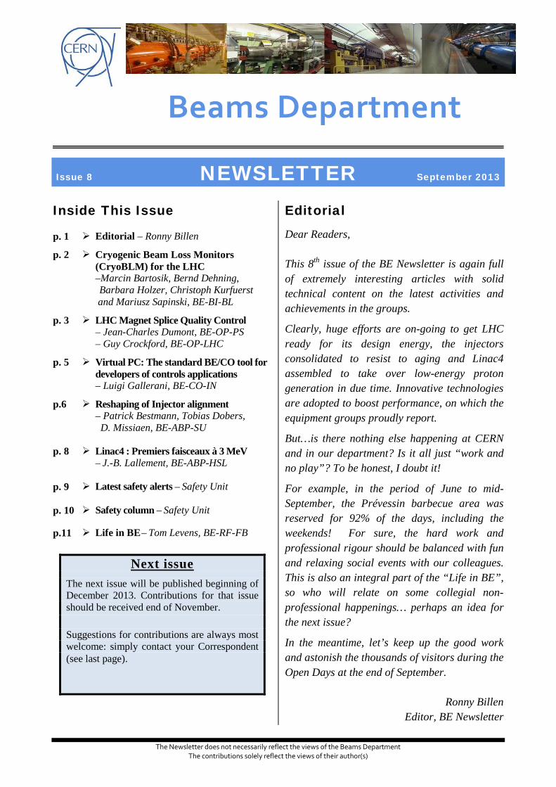
Cryogenic Beam Loss Monitors (CryoBLM) for the LHC The protection ability of the current BLM system around the triplet magnets at the LHC interaction regions is not maintained for all loss scenarios for higher beam energies and intensities. The envisaged solution is to install particle detectors as close as possible to the superconducting coil, which means inside the cold mass of the magnets (shown in illustration 1). This allows improved protection for the high-luminosity LHC. Prior to this thesis work, no detector technology had been proven to work under the conditions encountered at this location.
Illustration 1: MQXF cross section (courtesy of P. Ferracin) with the current BLM placement and the future possible CryoBLM location. The new monitors will be closer to the element needing protection and to the loss location.
Three detector technologies were selected for further investigations: silicon sensors, diamond detectors and a Liquid Helium (LHe) ionisation chamber. Silicon detectors are widely in use for particle detection and possess promising properties at cryogenic temperatures. Diamond detectors have the main advantages to generate significantly less leakage current at room temperature and to be more radiation hard compared to silicon material. The liquid helium chamber is a completely new in house produced prototype. Its main advantage is to be insensitive to radiation damage. The downside is the extremely low charge mobility, which is 5 orders of magnitude lower than for diamond material. Measurements in the laboratory with laser and alpha source allowed drawing a detailed picture of the charge carrier properties in the semiconductor detectors down to LHe temperatures.
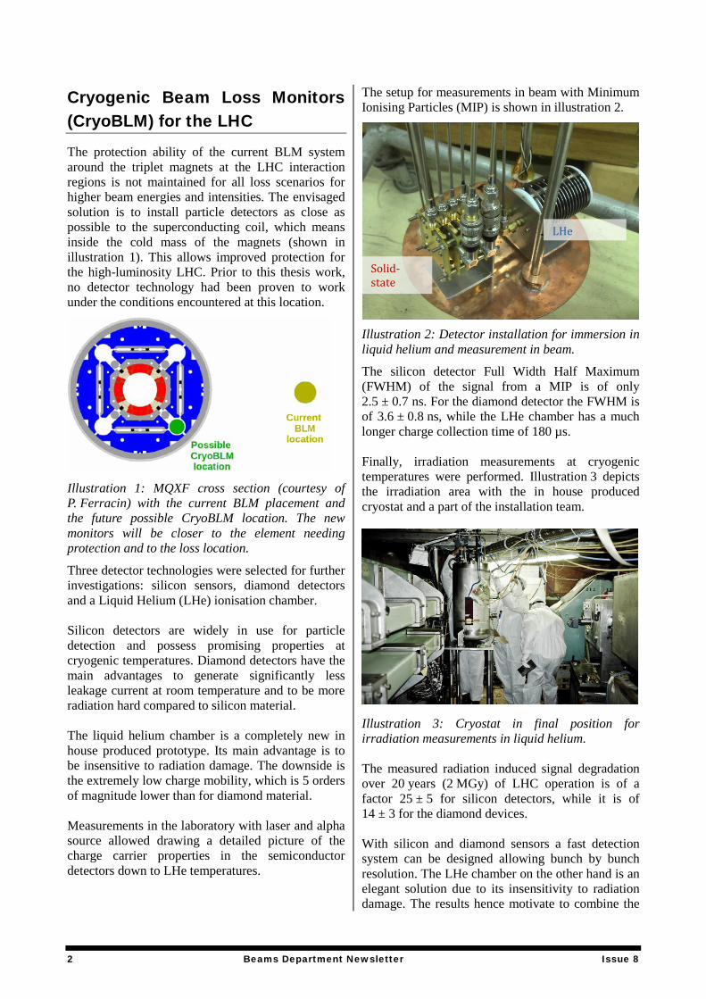
The setup for measurements in beam with Minimum Ionising Particles (MIP) is shown in illustration 2.
Illustration 2: Detector installation for immersion in liquid helium and measurement in beam.
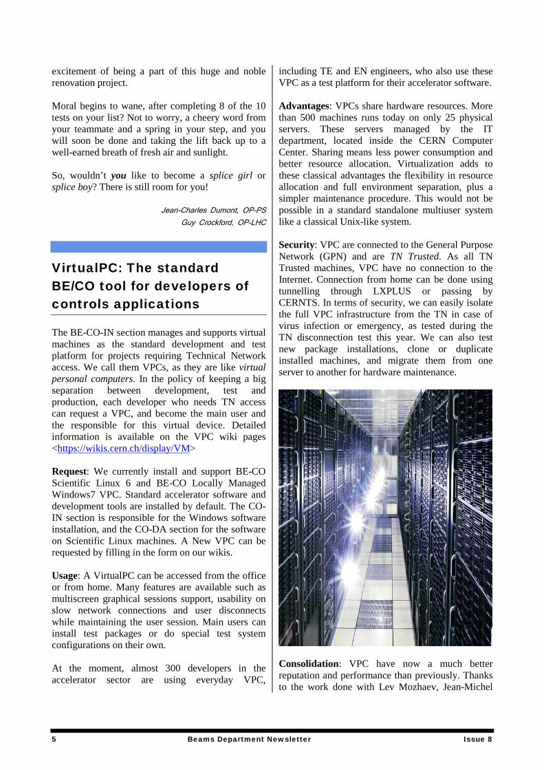
The silicon detector Full Width Half Maximum (FWHM) of the signal from a MIP is of only 2.5 ± 0.7 ns. For the diamond detector the FWHM is of 3.6 ± 0.8 ns, while the LHe chamber has a much longer charge collection time of 180 µs. Finally, irradiation measurements at cryogenic temperatures were performed. Illustration 3 depicts the irradiation area with the in house produced cryostat and a part of the installation team.
Illustration 3: Cryostat in final position for irradiation measurements in liquid helium. The measured radiation induced signal degradation over 20 years (2 MGy) of LHC operation is of a factor 25 ± 5 for silicon detectors, while it is of 14 ± 3 for the diamond devices. With silicon and diamond sensors a fast detection system can be designed allowing bunch by bunch resolution. The LHe chamber on the other hand is an elegant solution due to its insensitivity to radiation damage. The results hence motivate to combine the
Solid-state
LHe
2 Beams Department Newsletter Issue 8

advantages, by using solid-state detectors for a fast protection system, while the LHe chamber can be used in parallel for calibration and for the protection from steady state losses. Further measurements, models, simulations and the installation of first CryoBLM prototypes during LS1 will allow additional conclusions. The project efforts have been supported by: T. Eisel (with the CERN Cryolab), C. Arregui Rementeria, A. Mereghetti, E. Griesmayer (CIVIDEC), C. Weiss, L. Gatignon, M. Glaser, F. Ravotti, V. Eremin (IOFFE institute), J. Haerkoenen (RD39), E. Verbitskaya (IOFFE institute), E. Guillermain, H. Pernegger, H. Jansen, V. Parma, T. Renaglia and many members of the BI-group. Thank you,
Marcin Bartosik, Bernd Dehning, Barbara Holzer,
Christoph Kurfuerst and Mariusz Sapinski, BE-BI-BL
LHC Magnet Splice Quality Control The main objective of LS1 is to consolidate CERN’s flagship machine, the LHC, in order to achieve the design energy of 7TeV per beam. Quality control of consolidated magnet interconnects (or splices) is an important step in this process. Let us not forget the September 2008 incident! To achieve the high magnetic field at 7 TeV, each 3km chain of 154 magnet dipoles must run at a current of about 12 kA. For this reason, the LHC magnets are superconducting. Super conductivity appears at ultra-low temperatures, achieved by cooling the magnets with liquid helium. It’s a non-resistive state of the matter which can easily break down due to any local warming, known as a “quench”. A bad magnet connection will give rise to an electrical resistance, Joule effect and possible local destruction of the conductor burnt by the high intensity current. Therefore the 10170 splices around the LHC need to be checked conscientiously. This is a long and arduous task, requiring a team of highly motivated volunteers (the splice girls and splice boys), just part of the CERN global effort to prepare the LHC for its next phase to explore the mysteries of nature, by recreating conditions ever closer to the Big Bang.
What’s in a splice?
Fig 1: LHC main splice (superconducting cables and copper stabilizer) Teams are organized on a weekly basis, being a volunteer, you’ll work each week with a different colleague. For the time being, all the action is happening over at point 6. The site has been equipped with extra facilities, changing rooms, showers and eating area to make point 6 feels like at home. You will spend the whole week in a dual collaboration during where you will sometimes be on your knees, crawling under magnets. Add a few kilometers of bicycling around the tunnel, and you have the perfect fitness workout to get in shape and CERN even pays you for it! As part of the team, you’re in charge of checking the splices by following specific procedures. To do this you’re equipped with specific tools built to measure if the splice quality is up to scratch. You have several different tests to execute following your daily mission plan. • Quality Control (QC) of existing main
interconnection splices. • QC of superconducting cables. • QC of repaired main interconnection splices. • QC of interconnect after preparation for shunt
soldering. • QC of consolidated main interconnection splices
(shunt soldered in place). • QC of insulation box. Have you carefully prepared your bag with the appropriate tools?
3 Beams Department Newsletter Issue 8

Mechanical gauges, µΩ meter (Megger), pens, lamp, PC, mirror, calliper. Add on top of all that your biocell and other mandatory personal safety equipment, and you are now carrying 20 kg in the rucksack on your back. Are all your batteries fully charged? No more power on your computer or Megger means a long bike ride back to base camp. You are now ready to go 100 m down underground and ride your bike to reach the first magnet of your daily list. It is called QBQI.16L6 and it’s a shunt? (A consolidated interconnection) You have a long ride ahead, but it’s a good way to stretch the sinews before tackling this one hour test. Some details about the tests: Visual inspection consists of checking several parameters: • No gaps visible on the splice. • Mechanically correctly mounted. • No surface defaults (after being machined to
prepare for the addition of the shunt, the bus bar surface should be perfectly flat and smooth).
• Solder is present everywhere, no delaminated parts (for the consolidated interconnection, the shunt provides two reservoirs, full of solder which should infiltrate under during the soldering action. This we check because it’s a good indication if the soldering process has been properly carried out).
• No major vertical or horizontal deformations preventing correct shunt installation.
Measuring the geometry:
Fig 2: Marking the splice for R8/R16 measurements Superconducting cables must conform to a precise length. The machining process, for a shunt installation, reduces the height of the bus bar.
However this must fall within defined limits. Finally the shunt positioning must be accurate, with respect to the distance from the extremity of the interconnection. Electrical Measurements: The resistance of each splices is measured with a precise test, the so-called R8/R16 test. It consists of marking the copper from the center to the extremities with 8 cm length (which results in measuring on the two sides of the connection). Then using a device called the Megger, we measure three times the resistance from the center to the left, then to the right and finally between left and right part of the splice (R16) to crosscheck the previous measurements.
Fig 3: R8 measurement In the case of a consolidated splice (after shunt installation), also the RTop-side measurements have to be performed (in addition to R8/R16 measurements). These measurements are meant to check the electrical contact between the splice and the shunt. All this makes a large number of acquisitions gathered by software specially developed. This software also guides us through the procedures and triggers alarms in the case of abnormal values. Recent statistics on the test results show how many interconnects need to be re-done. Sector 5-6: 24.8% non-conform and sector 6-7: 29% non-conform. This all goes to show that we have our work cut out during LS1. Once you completed the procedure for a test, you gather all your equipment and go to the next magnet on your test list. On the way you can see other teams working. It’s a real hive of activity underground. Some teams are soldering, some are machining and some others are doing QC tests. This is a unique experience. You quickly get to know your QC partner as you endure together the hardships and
4 Beams Department Newsletter Issue 8
excitement of being a part of this huge and noble renovation project. Moral begins to wane, after completing 8 of the 10 tests on your list? Not to worry, a cheery word from your teammate and a spring in your step, and you will soon be done and taking the lift back up to a well-earned breath of fresh air and sunlight. So, wouldn’t you like to become a splice girl or splice boy? There is still room for you!
Jean-Charles Dumont, OP-PS Guy Crockford, OP-LHC
VirtualPC: The standard BE/CO tool for developers of controls applications
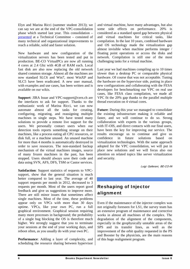
The BE-CO-IN section manages and supports virtual machines as the standard development and test platform for projects requiring Technical Network access. We call them VPCs, as they are like virtual personal computers. In the policy of keeping a big separation between development, test and production, each developer who needs TN access can request a VPC, and become the main user and the responsible for this virtual device. Detailed information is available on the VPC wiki pages <https://wikis.cern.ch/display/VM> Request: We currently install and support BE-CO Scientific Linux 6 and BE-CO Locally Managed Windows7 VPC. Standard accelerator software and development tools are installed by default. The CO-IN section is responsible for the Windows software installation, and the CO-DA section for the software on Scientific Linux machines. A New VPC can be requested by filling in the form on our wikis. Usage: A VirtualPC can be accessed from the office or from home. Many features are available such as multiscreen graphical sessions support, usability on slow network connections and user disconnects while maintaining the user session. Main users can install test packages or do special test system configurations on their own. At the moment, almost 300 developers in the accelerator sector are using everyday VPC,
including TE and EN engineers, who also use these VPC as a test platform for their accelerator software. Advantages: VPCs share hardware resources. More than 500 machines runs today on only 25 physical servers. These servers managed by the IT department, located inside the CERN Computer Center. Sharing means less power consumption and better resource allocation. Virtualization adds to these classical advantages the flexibility in resource allocation and full environment separation, plus a simpler maintenance procedure. This would not be possible in a standard standalone multiuser system like a classical Unix-like system. Security: VPC are connected to the General Purpose Network (GPN) and are TN Trusted. As all TN Trusted machines, VPC have no connection to the Internet. Connection from home can be done using tunnelling through LXPLUS or passing by CERNTS. In terms of security, we can easily isolate the full VPC infrastructure from the TN in case of virus infection or emergency, as tested during the TN disconnection test this year. We can also test new package installations, clone or duplicate installed machines, and migrate them from one server to another for hardware maintenance.
Consolidation: VPC have now a much better reputation and performance than previously. Thanks to the work done with Lev Mozhaev, Jean-Michel
5 Beams Department Newsletter Issue 8
Elyn and Marina Ricci (summer student 2013); we can say we are at the end of the VPC-consolidation phase which started last year. This consolidation – presented at a Technical Committee – consisted of many technical and organizational improvements to reach a reliable, solid and faster solution. New hardware and new configuration of the virtualization servers has been tested and put in production. BE-CO VirtualPCs are now all running 4 cores at 2.4 Ghz with 4GB of RAM each. Local fast disk are also now replacing the old network shared common storage. Almost all the machines are now standard SLC6 and Win7, most WinXP and SLC5 have been eradicated. A new user manual, with examples and use cases, has been written and is available on our wikis. Support: JIRA Issue and [email protected] are the interfaces to ask for support. Thanks to the enthusiastic work of Marina Ricci, we can now automate almost all the tasks for creating, configuring, migrating, and reassigning multiple machines in single steps. We have tested many solutions to provide a remote live support for the users. We personally contact users when our detection tools reports something strange on their machines, like a process eating all CPU resources, or disk full, or a machine unused. An unused machine for more than 4 months is automatically destroyed in order to save resources. The non-standard backup mechanism of the virtual machines images, source of many frozen machines in the past, has been stopped. Users should always save their code and data using SVN, AFS, DFS, TSM or Castor services. Satisfaction: Support statistics of requests to VPC-support, show that the general situation is much better compared to last year. The average of 40 support requests per month in 2012, decreased to 3 requests per month. Most of the users report good feedback and give us suggestions to improve more. There are still minor issues that sometimes affect single machines. Most of the time, these problems appear only on VPCs with more than 30 days uptime. VPCs, like your own PC, run a full graphical environment. Graphical session requiring many more processes in background; the probability of a single bug blocking the OS is therefore much higher. We strongly suggest that you to terminate your sessions at the end of your working days, and reboot often, as you usually do with your own PC. Performance: Adding a layer of complexity, and scheduling the resource sharing between hypervisor
and virtual machine, have many advantages, but also some side effects on performance. 20% is considered as a standard speed gap between physical and virtual machines for critical tasks, like compilation. In the last 10 years, combined hardware and OS technology made the virtualization gap almost invisible when machine performs integer / floating point operations or access the disks and network. Compilation is still one of the most challenging tasks for a virtual machine. Last year we had machines compiling up to 10 times slower than a desktop PC or comparable physical hardware. Of course that was not acceptable. Tuning the hardware on the hypervisor side, putting in place new configurations and collaborating with the FESA developers for benchmarking our VPC on real use cases, like FESA class compilation, we made all VPC fit the 20% gap thanks to the parallel multiple thread execution on 4 virtual cores. Future: During this year we managed to consolidate the existing infrastructure making it reliable and faster, and we will continue to do so. Strong collaboration with experts in the various groups, with IT-OIS, and direct contacts with our final users, have been the key for improving our service. The results encourage us to continue and give us confidence in future solutions based on virtualization technologies. With the same approach adopted for the VPC consolidation, we will put in place new solutions and we will focus also our attention on related topics like server virtualization and security.
Luigi Gallerani, BE-CO-IN
Reshaping of Injector alignment
Even if the maintenance of the injector complex was not originally foreseen for LS1, the survey team has an extensive program of maintenance and corrective works in almost all machines of the complex. The degradation of the alignment of the components, especially in the geophysically unstable areas of the SPS and its transfer lines, as well as the improvement of the orbit quality requested in the PS and Booster by the physicists, are the main reasons of this huge realignment program.
6 Beams Department Newsletter Issue 8
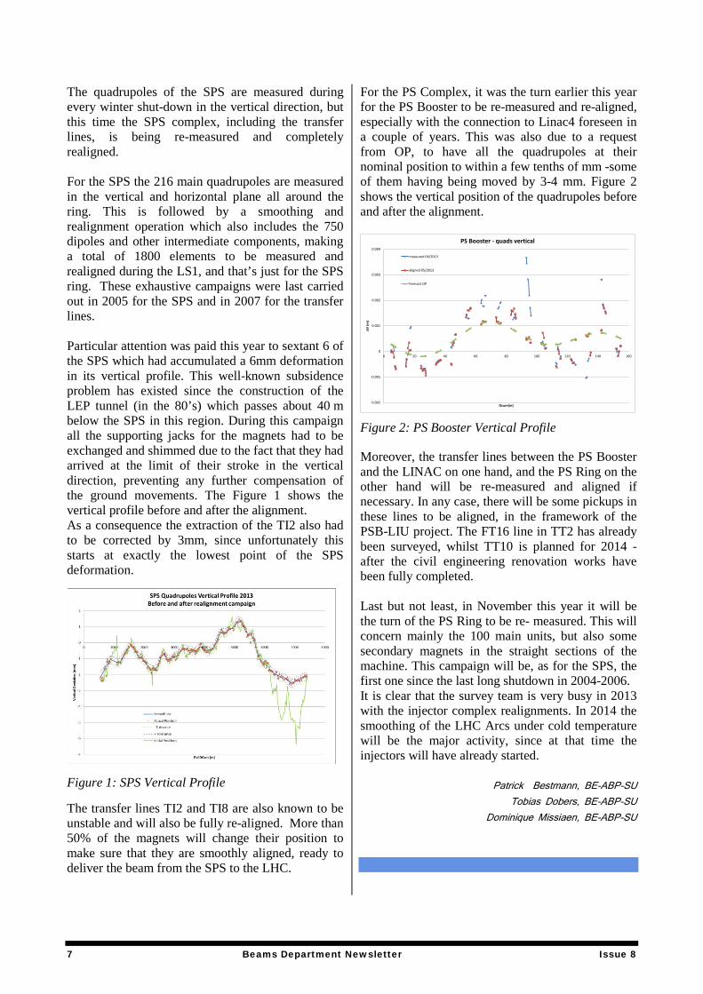
The quadrupoles of the SPS are measured during every winter shut-down in the vertical direction, but this time the SPS complex, including the transfer lines, is being re-measured and completely realigned. For the SPS the 216 main quadrupoles are measured in the vertical and horizontal plane all around the ring. This is followed by a smoothing and realignment operation which also includes the 750 dipoles and other intermediate components, making a total of 1800 elements to be measured and realigned during the LS1, and that’s just for the SPS ring. These exhaustive campaigns were last carried out in 2005 for the SPS and in 2007 for the transfer lines. Particular attention was paid this year to sextant 6 of the SPS which had accumulated a 6mm deformation in its vertical profile. This well-known subsidence problem has existed since the construction of the LEP tunnel (in the 80’s) which passes about 40 m below the SPS in this region. During this campaign all the supporting jacks for the magnets had to be exchanged and shimmed due to the fact that they had arrived at the limit of their stroke in the vertical direction, preventing any further compensation of the ground movements. The Figure 1 shows the vertical profile before and after the alignment. As a consequence the extraction of the TI2 also had to be corrected by 3mm, since unfortunately this starts at exactly the lowest point of the SPS deformation.
Figure 1: SPS Vertical Profile The transfer lines TI2 and TI8 are also known to be unstable and will also be fully re-aligned. More than 50% of the magnets will change their position to make sure that they are smoothly aligned, ready to deliver the beam from the SPS to the LHC.
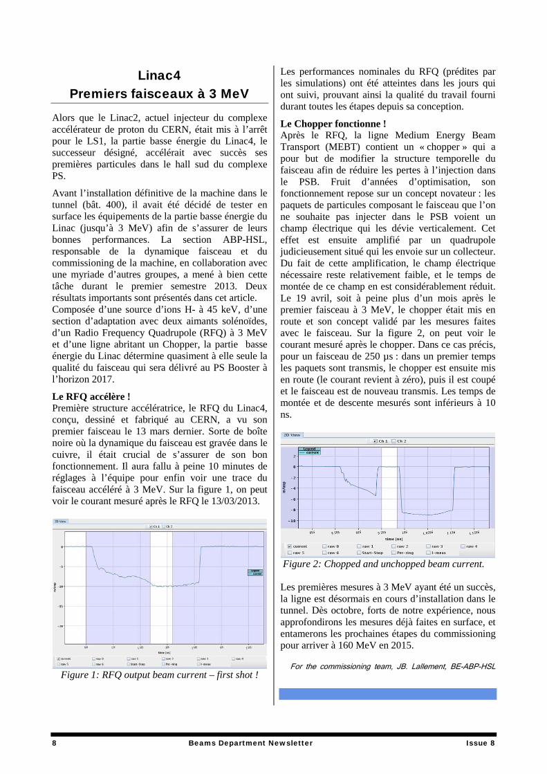
For the PS Complex, it was the turn earlier this year for the PS Booster to be re-measured and re-aligned, especially with the connection to Linac4 foreseen in a couple of years. This was also due to a request from OP, to have all the quadrupoles at their nominal position to within a few tenths of mm -some of them having being moved by 3-4 mm. Figure 2 shows the vertical position of the quadrupoles before and after the alignment.
Figure 2: PS Booster Vertical Profile
Moreover, the transfer lines between the PS Booster and the LINAC on one hand, and the PS Ring on the other hand will be re-measured and aligned if necessary. In any case, there will be some pickups in these lines to be aligned, in the framework of the PSB-LIU project. The FT16 line in TT2 has already been surveyed, whilst TT10 is planned for 2014 -after the civil engineering renovation works have been fully completed. Last but not least, in November this year it will be the turn of the PS Ring to be re- measured. This will concern mainly the 100 main units, but also some secondary magnets in the straight sections of the machine. This campaign will be, as for the SPS, the first one since the last long shutdown in 2004-2006. It is clear that the survey team is very busy in 2013 with the injector complex realignments. In 2014 the smoothing of the LHC Arcs under cold temperature will be the major activity, since at that time the injectors will have already started.
Patrick Bestmann, BE-ABP-SU Tobias Dobers, BE-ABP-SU
Dominique Missiaen, BE-ABP-SU
-0.002
-0.001
0
0.001
0.002
0.003
0.004
0 20 40 60 80 100 120 140 160
dV (m
)
Dcum(m)
PS Booster - quads vertical
measured 04/2013
aligned 05/2013
forecast OP
7 Beams Department Newsletter Issue 8
Linac4 Premiers faisceaux à 3 MeV
Alors que le Linac2, actuel injecteur du complexe accélérateur de proton du CERN, était mis à l’arrêt pour le LS1, la partie basse énergie du Linac4, le successeur désigné, accélérait avec succès ses premières particules dans le hall sud du complexe PS.
Avant l’installation définitive de la machine dans le tunnel (bât. 400), il avait été décidé de tester en surface les équipements de la partie basse énergie du Linac (jusqu’à 3 MeV) afin de s’assurer de leurs bonnes performances. La section ABP-HSL, responsable de la dynamique faisceau et du commissioning de la machine, en collaboration avec une myriade d’autres groupes, a mené à bien cette tâche durant le premier semestre 2013. Deux résultats importants sont présentés dans cet article. Composée d’une source d’ions H- à 45 keV, d’une section d’adaptation avec deux aimants solénoïdes, d’un Radio Frequency Quadrupole (RFQ) à 3 MeV et d’une ligne abritant un Chopper, la partie basse énergie du Linac détermine quasiment à elle seule la qualité du faisceau qui sera délivré au PS Booster à l’horizon 2017.
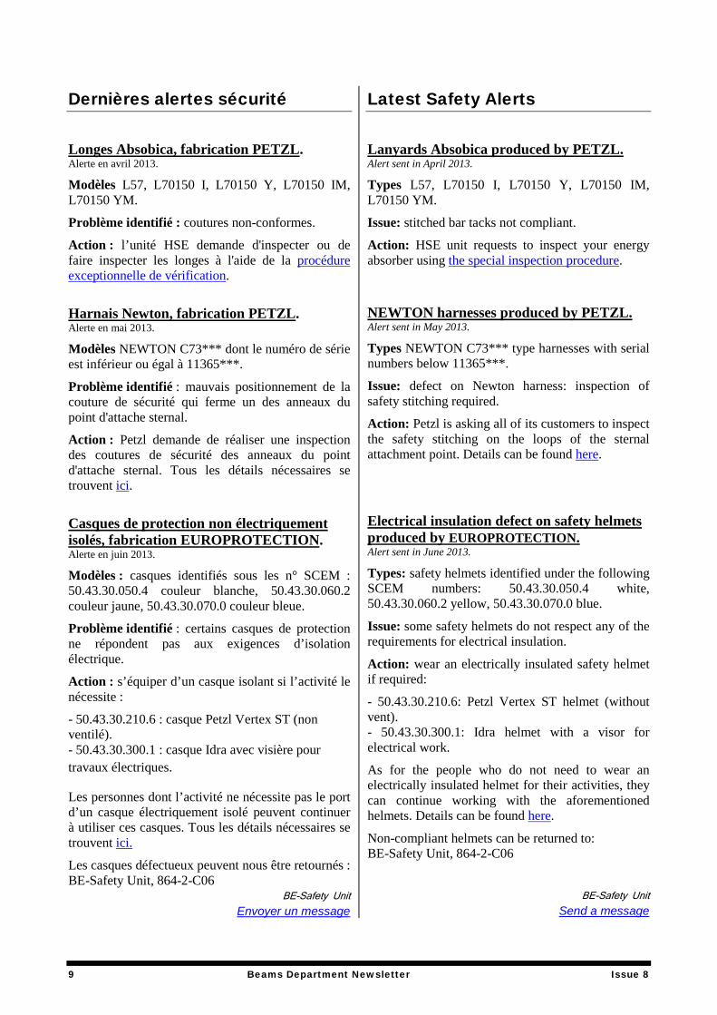
Le RFQ accélère ! Première structure accélératrice, le RFQ du Linac4, conçu, dessiné et fabriqué au CERN, a vu son premier faisceau le 13 mars dernier. Sorte de boîte noire où la dynamique du faisceau est gravée dans le cuivre, il était crucial de s’assurer de son bon fonctionnement. Il aura fallu à peine 10 minutes de réglages à l’équipe pour enfin voir une trace du faisceau accéléré à 3 MeV. Sur la figure 1, on peut voir le courant mesuré après le RFQ le 13/03/2013.
Figure 1: RFQ output beam current – first shot !
Les performances nominales du RFQ (prédites par les simulations) ont été atteintes dans les jours qui ont suivi, prouvant ainsi la qualité du travail fourni durant toutes les étapes depuis sa conception.
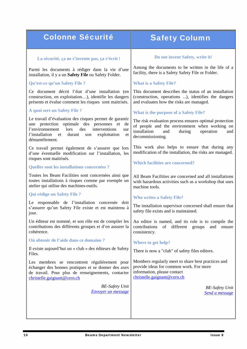
Le Chopper fonctionne ! Après le RFQ, la ligne Medium Energy Beam Transport (MEBT) contient un « chopper » qui a pour but de modifier la structure temporelle du faisceau afin de réduire les pertes à l’injection dans le PSB. Fruit d’années d’optimisation, son fonctionnement repose sur un concept novateur : les paquets de particules composant le faisceau que l’on ne souhaite pas injecter dans le PSB voient un champ électrique qui les dévie verticalement. Cet effet est ensuite amplifié par un quadrupole judicieusement situé qui les envoie sur un collecteur. Du fait de cette amplification, le champ électrique nécessaire reste relativement faible, et le temps de montée de ce champ en est considérablement réduit. Le 19 avril, soit à peine plus d’un mois après le premier faisceau à 3 MeV, le chopper était mis en route et son concept validé par les mesures faites avec le faisceau. Sur la figure 2, on peut voir le courant mesuré après le chopper. Dans ce cas précis, pour un faisceau de 250 µs : dans un premier temps les paquets sont transmis, le chopper est ensuite mis en route (le courant revient à zéro), puis il est coupé et le faisceau est de nouveau transmis. Les temps de montée et de descente mesurés sont inférieurs à 10 ns.
Figure 2: Chopped and unchopped beam current. Les premières mesures à 3 MeV ayant été un succès, la ligne est désormais en cours d’installation dans le tunnel. Dès octobre, forts de notre expérience, nous approfondirons les mesures déjà faites en surface, et entamerons les prochaines étapes du commissioning pour arriver à 160 MeV en 2015.
For the commissioning team, JB. Lallement, BE-ABP-HSL
8 Beams Department Newsletter Issue 8
Dernières alertes sécurité
Longes Absobica, fabrication PETZL. Alerte en avril 2013.
Modèles L57, L70150 I, L70150 Y, L70150 IM, L70150 YM.
Problème identifié : coutures non-conformes.
Action : l’unité HSE demande d'inspecter ou de faire inspecter les longes à l'aide de la procédure exceptionnelle de vérification.
Harnais Newton, fabrication PETZL. Alerte en mai 2013.
Modèles NEWTON C73*** dont le numéro de série est inférieur ou égal à 11365***.
Problème identifié : mauvais positionnement de la couture de sécurité qui ferme un des anneaux du point d'attache sternal.
Action : Petzl demande de réaliser une inspection des coutures de sécurité des anneaux du point d'attache sternal. Tous les détails nécessaires se trouvent ici.
Casques de protection non électriquement isolés, fabrication EUROPROTECTION. Alerte en juin 2013. Modèles : casques identifiés sous les n° SCEM : 50.43.30.050.4 couleur blanche, 50.43.30.060.2 couleur jaune, 50.43.30.070.0 couleur bleue.
Problème identifié : certains casques de protection ne répondent pas aux exigences d’isolation électrique.
Action : s’équiper d’un casque isolant si l’activité le nécessite :
- 50.43.30.210.6 : casque Petzl Vertex ST (non ventilé). - 50.43.30.300.1 : casque Idra avec visière pour travaux électriques.
Les personnes dont l’activité ne nécessite pas le port d’un casque électriquement isolé peuvent continuer à utiliser ces casques. Tous les détails nécessaires se trouvent ici.
Les casques défectueux peuvent nous être retournés : BE-Safety Unit, 864-2-C06
BE-Safety Unit Envoyer un message
Latest Safety Alerts
Lanyards Absobica produced by PETZL. Alert sent in April 2013.
Types L57, L70150 I, L70150 Y, L70150 IM, L70150 YM.
Issue: stitched bar tacks not compliant.
Action: HSE unit requests to inspect your energy absorber using the special inspection procedure.
NEWTON harnesses produced by PETZL. Alert sent in May 2013.
Types NEWTON C73*** type harnesses with serial numbers below 11365***.
Issue: defect on Newton harness: inspection of safety stitching required.
Action: Petzl is asking all of its customers to inspect the safety stitching on the loops of the sternal attachment point. Details can be found here.
Electrical insulation defect on safety helmets produced by EUROPROTECTION. Alert sent in June 2013.
Types: safety helmets identified under the following SCEM numbers: 50.43.30.050.4 white, 50.43.30.060.2 yellow, 50.43.30.070.0 blue.
Issue: some safety helmets do not respect any of the requirements for electrical insulation.
Action: wear an electrically insulated safety helmet if required:
- 50.43.30.210.6: Petzl Vertex ST helmet (without vent). - 50.43.30.300.1: Idra helmet with a visor for electrical work.
As for the people who do not need to wear an electrically insulated helmet for their activities, they can continue working with the aforementioned helmets. Details can be found here.
Non-compliant helmets can be returned to: BE-Safety Unit, 864-2-C06
BE-Safety Unit
Send a message
9 Beams Department Newsletter Issue 8
Colonne Sécurité
La sécurité, ça ne s’invente pas, ça s’écrit !
Parmi les documents à rédiger dans la vie d’une installation, il y a un Safety File ou Safety Folder.
Qu’est-ce qu’un Safety File ?
Ce document décrit l’état d’une installation (en construction, en exploitation…), identifie les dangers présents et évalue comment les risques sont maitrisés.
A quoi sert un Safety File ?
Le travail d’évaluation des risques permet de garantir une protection optimale des personnes et de l’environnement lors des interventions sur l’installation et durant son exploitation et démantèlement.
Ce travail permet également de s’assurer que lors d’une éventuelle modification sur l’installation, les risques sont maitrisés.
Quelles sont les installations concernées ?
Toutes les Beam Facilities sont concernées ainsi que toutes installations à risques comme par exemple un atelier qui utilise des machines-outils.
Qui rédige un Safety File ?
Le responsable de l’installation concernée doit s’assurer qu’un Safety File existe et est maintenu à jour.
Un éditeur est nommé, et son rôle est de compiler les contributions des différents groupes et d’en assurer la cohérence.
Où obtenir de l’aide dans ce domaine ?
Il existe aujourd’hui un « club » des éditeurs de Safety Files.
Les membres se rencontrent régulièrement pour échanger des bonnes pratiques et se donner des axes de travail. Pour plus de renseignements, contacter [email protected]
BE-Safety Unit Envoyer un message
Safety Column
Do not invent Safety, write it! Among the documents to be written in the life of a facility, there is a Safety Safety File or Folder. What is a Safety File?
This document describes the status of an installation (construction, operations ...), identifies the dangers and evaluates how the risks are managed. What is the purpose of a Safety File?
The risk evaluation process ensures optimal protection of people and the environment when working on installation and during operation and decommissioning. This work also helps to ensure that during any modification of the installation, the risks are managed. Which facilities are concerned?
All Beam Facilities are concerned and all installations with hazardous activities such as a workshop that uses machine tools. Who writes a Safety File?
The installation supervisor concerned shall ensure that safety file exists and is maintained. An editor is named, and its role is to compile the contributions of different groups and ensure consistency. Where to get help?
There is now a "club" of safety files editors. Members regularly meet to share best practices and provide ideas for common work. For more information, please contact [email protected]
BE-Safety Unit Send a message
10 Beams Department Newsletter Issue 8
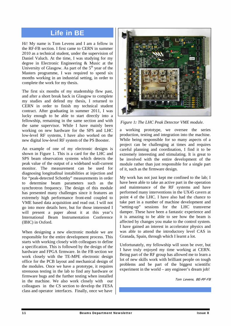
Life in BE Hi! My name is Tom Levens and I am a fellow in the RF-FB section. I first came to CERN in summer 2010 as a technical student, under the supervision of Daniel Valuch. At the time, I was studying for my degree in Electronic Engineering & Music at the University of Glasgow. As part of the 5th year of the Masters programme, I was required to spend six months working in an industrial setting, in order to complete the work for my thesis. The first six months of my studentship flew past, and after a short break back in Glasgow to complete my studies and defend my thesis, I returned to CERN in order to finish my technical student contract. After graduating in summer 2011, I was lucky enough to be able to start directly into a fellowship, remaining in the same section and with the same supervisor. While I have mainly been working on new hardware for the SPS and LHC low-level RF systems, I have also worked on the new digital low-level RF system of the PS Booster. An example of one of my electronic designs is shown in Figure 1. This is a card for the LHC and SPS beam observation systems which detects the peak value of the output of a wideband wall-current monitor. The measurement can be used for diagnosing longitudinal instabilities at injection and for “peak-detected Schottky” measurements in order to determine beam parameters such as the synchrotron frequency. The design of this module has presented many challenges since it features an extremely high performance front-end coupled to VME based data acquisition and read out. I will not go into more details here, but for those interested I will present a paper about it at this year’s International Beam Instrumentation Conference (IBIC) in Oxford. When designing a new electronic module we are responsible for the entire development process. This starts with working closely with colleagues to define a specification. This is followed by the design of the hardware and FPGA firmware. In the FB section we work closely with the TE-MPE electronic design office for the PCB layout and mechanical design of the modules. Once we have a prototype, it requires strenuous testing in the lab to find any hardware or firmware bugs and the further testing when installed in the machine. We also work closely with our colleagues in the CS section to develop the FESA class and operator interfaces. Finally, once we have
a working prototype, we oversee the series production, testing and integration into the machine. While being responsible for so many aspects of a project can be challenging at times and requires careful planning and coordination, I find it to be extremely interesting and stimulating. It is great to be involved with the entire development of the module rather than just responsible for a single part of it, such as the firmware design. My work has not just kept me confined to the lab; I have been able to take an active part in the operation and maintenance of the RF systems and have performed many interventions in the UX45 cavern at point 4 of the LHC. I have also had the chance to take part in a number of machine development and “setting-up” sessions for the LHC transverse damper. These have been a fantastic experience and it is amazing to be able to see how the beam is affected by changes you make to the control system. I have gained an interest in accelerator physics and was able to attend the introductory level CAS in Granada, Spain, through which I learnt a lot. Unfortunately, my fellowship will soon be over, but I have truly enjoyed my time working at CERN. Being part of the RF group has allowed me to learn a lot of new skills work with brilliant people on tough problems and be part of the biggest scientific experiment in the world – any engineer’s dream job!
Tom Levens, BE-RF-FB
Figure 1: The LHC Peak Detector VME module.
11 Beams Department Newsletter Issue 8
Newsletter Contacts
Correspondents:
ABP E. Benedetto & H. Mainaud Durand
ASR A. Di Luca
BI E. B. Holzer
CO M. Draper
OP C. Kittel
RF W. Höfle
Copy Editor L. Van Cauter-Tanner
Editor-In-Chief R. Billen
12 Beams Department Newsletter Issue 8