Embed Size (px)
Citation preview

Guardian Fall Protection, Inc. 800-466-6385 26609 79th Ave. South, Kent, WA 98032 253-854-5877
1 of 16
BEAMGUARD SAFETY POSTTM
INSTRUCTIONS
READ THESE WARNINGS BEFORE USING THE BEAMGUARD SAFETY POST™!
1. Before use of this system, read and understand all instructions, warnings, cautions and
notes marked on the equipment and contained in these instructions. 2. Although we use standard safety equipment, this Beamguard Safety PostTM is designed
and tested as a system. Use of components that have not been designed and/or tested for use with this system can be dangerous and lead to injury or death. Contact Guardian if you are unsure about using an equivalent product.
3. You may attach personal fall protection equipment directly to a BeamguardTM. Do not
climb above the base of the BeamguardTM when using the top as an anchor point. Do not allow a hook to bind on the post - if using a double lock hook, use a carabiner or other intermediate connector to insure the hook on the lanyard cannot be side loaded. Only one person is allowed to tie off directly to a post. Only use lanyards or retractables that provide shock absorbency and deliver less than 1400 lbs. of force when tying off directly to a post.
4. Treat the safety post with respect. Your life is on the line! Use care when moving,
shipping, or storing BeamguardTM. Do not hammer on the device, except to strike the wing nuts. Although they are durable and made of steel, they must withstand tremendous force during a fall. Kinks, bends, or dents in the tube or cracks or breaks in the welds or steel plates can affect the way the system works. If damaged from rough handling - remove from service and return to Guardian for inspection or replacement.
5. Any fall protection equipment that is involved in a personnel fall incident or is struck by a
weight shall be removed from service immediately and discarded or returned to Guardian for inspection.
6. Failure to install, use, and/or remove BeamguardTM equipment in a safe manner by skilled
and trained craftsmen can result in serious injury or death. Until the Beamguard TM system is properly installed, use alternate fall protection means. Ask your supervisor for proper training.
7. BeamguardTM allows for stanchion spacing up to 60'. The BeamguardTM is designed for up
to two workers weighing no more than 310 each, per section. Workers must wear a
Guardian Fall Protection, Inc. 800-466-6385 26609 79th Ave. South, Kent, WA 98032 253-854-5877
2 of 16
Guardian full body harness, or equivalent, and shock absorbing lanyard designed to reduce fall forces to 900 lbs. or less.
8. It is critical to tighten the Guardian Quick Rod™ flange hooks. Those hooks hold the posts
onto the beam. Each shift, shake the posts to insure they are still snug. Strike the wing nut with a tool to snug up. Do not hammer excessively. The bolts on the underside should be tight to take up any space between the top of the base plate and the top flange. NOTE: Replace underside mounting bolts if visibly worn.
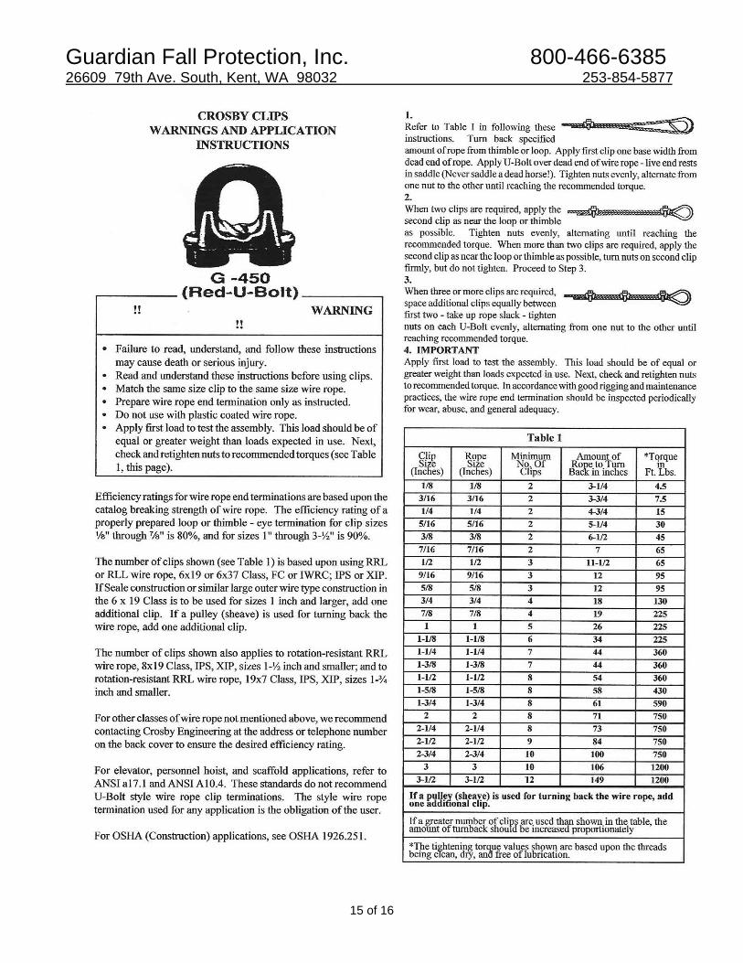
9. Use 3/8" wire rope supplied or specified by Guardian, or equivalent. It is critical to properly
torque all nuts on wire rope clamps to prevent the cable from slipping. See wire rope clamp manufacturers’ information or information in this guide. Slippage of the cable clamps may result in system failure!
10. The BeamguardTM and cable are single use items. If involved in arresting a fall or if the
system is struck with a weight (or a load), the units involved should be taken out of service and replaced. Contact Guardian @ 1-800-466-6385 for assistance.
11. The side safety cables are not slings, and are not intended for use other than on the side
of BeamguardTM. If used for any other purpose they should be removed from further service in the Beamguard TM systems.
12. The BeamguardTM stops a fall by stretching of the cable, deflection and bending of the
shock absorbing posts, and extension of the personal shock absorbing lanyard or retracting lanyard. The test weight sagged the cable between 7' and 13' feet on a 10' to 60' system, respectively. This results in a total fall distance of as much as 14½’ below the beam or work level the worker falls from. (Our tests are run with a test weight to simulate a 310 lb. worker. The fall distance of a worker that weighs less will be substantially less.) Test your system with a sand bag (220 lbs.) or other weight if in doubt. Use of a shorter lanyard, a retracting lanyard, or closer spacing of the posts (including intermediate posts) greatly reduces the fall distance. Do not tighten the cables to shorten the fall. This increases the forces in the system.
13. The Guardian BeamguardTM was tested on rigidly supported 8 ½” wide W16 x 58 and 10"
wide W27 x 84 beams. The standard BeamguardTM assembly is designed to fit on top flanges of 4” to about 13½”. Longer Quick Rods are available for larger flanges and deeper bases and longer flange hooks are available for thicker flanges as well. Use on beams that are smaller or on unsupported steel members could have different results. Some deformation to the building structure or steel is possible when a fall occurs. Guardian is not responsible for the stability or quality of the structure that the BeamguardTM is mounted on, or for consequential damages to the structure due to effects of the fall.
14. This device does not guarantee your safety; Guardian does not guarantee that no injury
will occur if a person falls while working with this unit. Use of this device is only expected to reduce the likelihood of serious injury and limit the fall distance if a fall occurs. Other means should be considered to limit the likelihood of a fall as well.
Guardian Fall Protection, Inc. 800-466-6385 26609 79th Ave. South, Kent, WA 98032 253-854-5877
3 of 16
15. Once a worker has fallen, the employer must have a plan and a method to rescue him,
and give treatment for any injury he may have sustained in the fall. 16. The horizontal lifeline assemblies are designed to be connected to and disconnected from
the post only at the safety shackles. If cable is disassembled, or parts are missing, call Guardian for replacements.
17. Do not use Guardian equipment until you have been trained and fully understand the
device, its labels, and these instructions. Call Guardian if labels are missing or unreadable. Call Guardian with any questions regarding the safe installation, use, or removal of Guardian Safety Equipment, or if additional instructions are needed. Spanish translation or assistance with other languages is available.
18. DANGER - Horizontal lifeline position is important to the operation of the post. A
turnbuckle will be provided upon request and may be used to aid in final adjustment of the cable. But, it is not intended to be used to fully tighten the cable. DO NOT JUDGE TENSION BY EYE! Measure the sag in the cable at the mid point with a rule! DO NOT tighten the cable too much! Sag in the cable allows the cable to stretch, and the falling weight produces a better “sling angle” when the cable tightens, and reduces the forces on the safety posts.
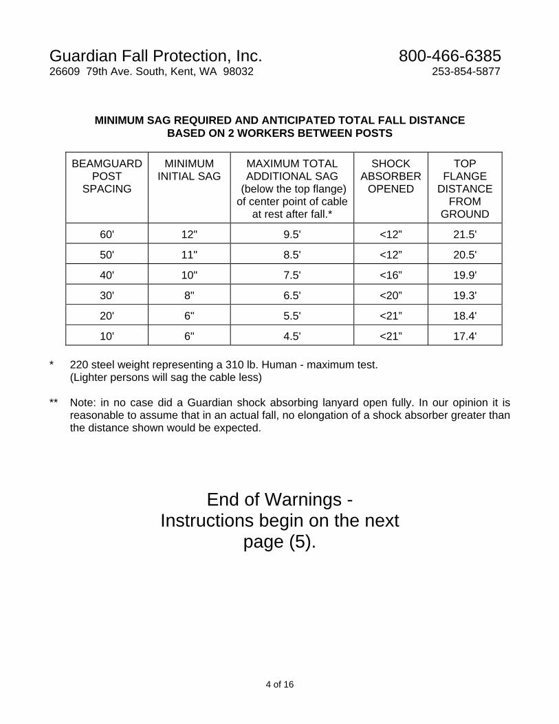
19. DANGER - Do not over tighten the cable. The cable must be 3/8" 7 x 19 Galvanized Air
Craft Cable, as supplied by Guardian or equal. Use of 3 (three) forged wire rope clips, or equivalent, is recommended to develop the termination/connections. Use thimbles in eye loops. Cables must have sag. Tightening the cable increases the force during a fall! The following table gives minimum sag for various spacing of posts. Increased sag in cable will result in increased total fall distance.
20. If a distance between posts is in between the steps on the chart enclosed, use the higher
sag distance. (For instance if the posts are spaced at 24 feet use the sag distance for 30' post spacing).
Guardian Fall Protection, Inc. 800-466-6385 26609 79th Ave. South, Kent, WA 98032 253-854-5877
4 of 16
MINIMUM SAG REQUIRED AND ANTICIPATED TOTAL FALL DISTANCE BASED ON 2 WORKERS BETWEEN POSTS
BEAMGUARD POST
SPACING
MINIMUM INITIAL SAG
MAXIMUM TOTAL ADDITIONAL SAG
(below the top flange) of center point of cable
at rest after fall.*
SHOCK ABSORBER
OPENED
TOP FLANGE
DISTANCE FROM
GROUND
60' 12" 9.5' <12” 21.5'
50' 11" 8.5' <12” 20.5'
40' 10" 7.5' <16” 19.9'
30' 8" 6.5' <20” 19.3'
20' 6" 5.5' <21” 18.4'
10' 6" 4.5' <21” 17.4'
* 220 steel weight representing a 310 lb. Human - maximum test.
(Lighter persons will sag the cable less) ** Note: in no case did a Guardian shock absorbing lanyard open fully. In our opinion it is
reasonable to assume that in an actual fall, no elongation of a shock absorber greater than the distance shown would be expected.
End of Warnings - Instructions begin on the next
page (5).
Guardian Fall Protection, Inc. 800-466-6385 26609 79th Ave. South, Kent, WA 98032 253-854-5877
5 of 16
INSTRUCTIONS FOR ERECTING A
BEAMGUARD SAFETY POST SYSTEMTM
1. Measure the distance in which you wish to have your BeamguardTM Safety Posts spaced to. (Although this is a matter of preference, if using these on a beam during erection of a structure it is recommended that there be about 2 feet between the BeamguardTM and the end of the beam. This allows the connector to sit outside of the post and make the connection of the next beam and the intersecting beam or joist. Also this allows about 4 feet between posts so a worker can easily transfer from one to another with two lanyards - insuring 100% fall protection. (Note: turnbuckles, if used, may make the travel distance between posts a bit longer especially if the cables with the turnbuckles are both oriented so the turnbuckles end up at the same end on two adjacent posts).
2. Adjust the length of the cable to be within 6" of that distance. (1' if using a turnbuckle.) 3. If using a turnbuckle, open the turnbuckle fully leaving at least three threads showing
inside the barrel. NOTE: DO NOT open the turnbuckle too far, threads must show on both sides of the barrel at all times. See note below - turnbuckles are not supplied with basic system and are optional.
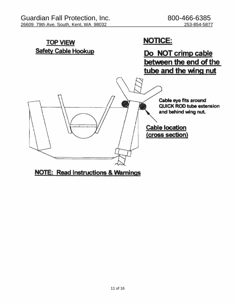
4. Attach cable to the eye on the top of the BeamguardTM using a safety shackle, and tighten
the shackle nut. Pin the shackle nut using a cotter pin, spring pin, or hitch key. 5. Install the safety post on one end of the beam by slipping the base plate over the top
flange and pushing it all the way on so that the back of the base plate rests against the outer edge of the top flange; tighten the bolts on the underside of the base plate first by hand.
6. Thread one flange hook onto the end of the Guardian QuickRodTM. Insure that the back
end is threaded onto the rod so that at least three threads show outside of the nut. Insert the QuickRodTM into the pipe sleeve on the top of the base plate. Pull the QuickRodTM through the pipe sleeve until the hook is fully engaged on the opposite flange; spin the wing nut on the end of the rod that is protruding out the back of the BeamguardTM pipe sleeve. Spin the wing nut up and strike it with a tool to tighten the bolt. Both QuickRodTM assemblies should be tightened.
7. Tighten the bolts on the underside of the BeamguardTM base plate with a wrench. It is not
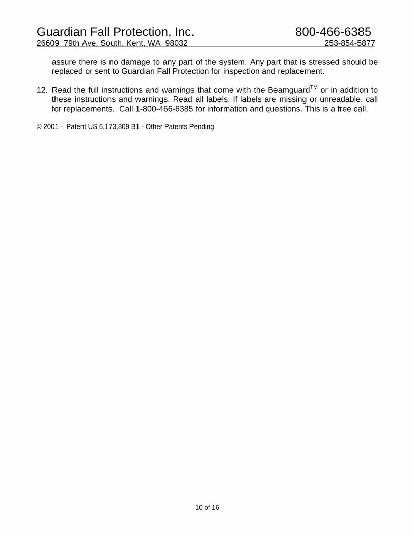
necessary to over tighten these bolts. 8. Attach the side safety cables to this end. The safety cable has two eyes. One has a sliding
sleeve. This is the bottom eye. Put the bottom eye around the wing nut and up underneath the outside QuickRodTM tube. Using a locking safety shackle attach the top eye of the side safety cable to the outside hole in the top plate of the BeamguardTM. Slide
Guardian Fall Protection, Inc. 800-466-6385 26609 79th Ave. South, Kent, WA 98032 253-854-5877
6 of 16
the sliding sleeve on the bottom eye down about half way to close the bottom eye slightly. 9. At the opposite end of the beam set the BeamguardTM on the flange approximately 2 feet
closer than its final resting point towards the first BeamguardTM. Attach the cable using the safety shackle and pin the safety shackle as before.
10. Slide the BeamguardTM along the top flange until the cable has the required sag as shown
in the charts in these instructions. Tighten the bottom flange bolts by hand. Note: (The posts are 42" tall. Therefore, if the sag ultimately required is 6”, then the center of the cable will be 36" off of the top flange at this point).
If using a turnbuckle leave approximately 3 inches of sag more than required by the charts in these instructions. Note: The posts are 42" tall. Therefore, if the sag ultimately required is 6”, the center of the cable will be approximately 33" off of the top flange at this point.
11. Once again, tighten the bottom nuts finger tight. Install the threaded flange hook onto the
QuickRodTM and insert through the pipe sleeves on top of the BeamguardTM base. Thread on the wing nuts and tighten each hook bolt by striking the wing nut with a tool (such as a hammer or your wrench).
12. Tighten the bolts on the bottom of the BeamguardTM using a wrench. It is not necessary to
over tighten these bolts. 13. Attach the side safety cables to this end. The safety cable has two eyes. One has a sliding
sleeve. This is the bottom eye. Put the bottom eye around the wing nut and up underneath the outside QuickRodTM tube. Using a locking safety shackle attach the top eye of the side safety cable to the outside hole in the top plate of the BeamguardTM. Slide the sliding sleeve on the bottom eye down about half way to close the bottom eye slightly.
14. Check the sag in the cable at the center point between the two posts it should be at least
as much as is shown in the charts in these instructions.
A. If using a turnbuckle, the worker must measure the sag in the cable with a rule (see chart in instructions) while another worker turns the turnbuckle until the sag is the amount specified in the chart.
B. Using a turnbuckle is optional. We suggest that most ironworkers and other tradesmen
using these systems would rather transition at the post to the next post in line without having to stop sliding their hook away from the post due to the obstruction that turnbuckles present. Another disadvantage of the turnbuckle includes the potential for a worker over-tightening the cable. This, plus the added cost and maintenance of the turnbuckles, outweigh any benefit gained in having the turnbuckle, such as in making the final sag adjustments, we feel, and most customers surveyed to date agree. We offer turnbuckles for those that prefer them.
WARNING: DO NOT OVER TIGHTEN THE CABLE The cable sag is important to allow stretch of the cable and to reduce the
Guardian Fall Protection, Inc. 800-466-6385 26609 79th Ave. South, Kent, WA 98032 253-854-5877
7 of 16
force on the safety posts. ************* 15. You are now ready to hook a safety lanyard to the horizontal cable and use it for fall arrest.
Each user should be wearing an approved safety harness and a safety lanyard not greater than 6' long with shock absorbing features that reduce inline forces to less than 900 pounds. INSURE THAT THE BEAM IS PROPERLY SECURED TO THE BUILDING TO WITHSTAND THE FORCES OF THE FALL. THE BEAM WILL TEND TO ROTATE SLIGHTLY DURING A FALL.
ADDITIONAL INFORMATION 1. When installing a continuance system (such as three posts over 120' with the second post
serving as an intermediate) first install the first section and adjust it and then each subsequent section thereafter. If using a Guardian Pass-ThruTM attachment on the top of the intermediate(s), check the sag in the longest section to meet or exceed the chart. See instructions.
2. NOTE: When installing BeamguardsTM on beams during conventional steel erection we
recommend that you keep the BeamguardTM about 2 feet back from the end of the beam to allow a connector to sit down on the beam and make up connections at the intersection. When transitioning from section to section, use a second lanyard to hook off to the next BeamguardTM section before removing the first lanyard from the previous section.
3. See chart enclosed for torque values of wire rope nuts as specified by the wire rope
clamp. 4. See enclosed drawings which portray a post system fully assembled (with an optional
turnbuckle) and other attachment graphics. 5. When using a longer cable than is necessary, reduce the length of the cable by loosening
the wire rope nuts and sliding the cable around the thimble and through the wire rope clips. Store spare cable by coiling it and hanging it on the end near the BeamguardTM post. Always check the torque of the wire rope nuts and insure that the clamps are tight.
Guardian Fall Protection, Inc. 800-466-6385 26609 79th Ave. South, Kent, WA 98032 253-854-5877
8 of 16
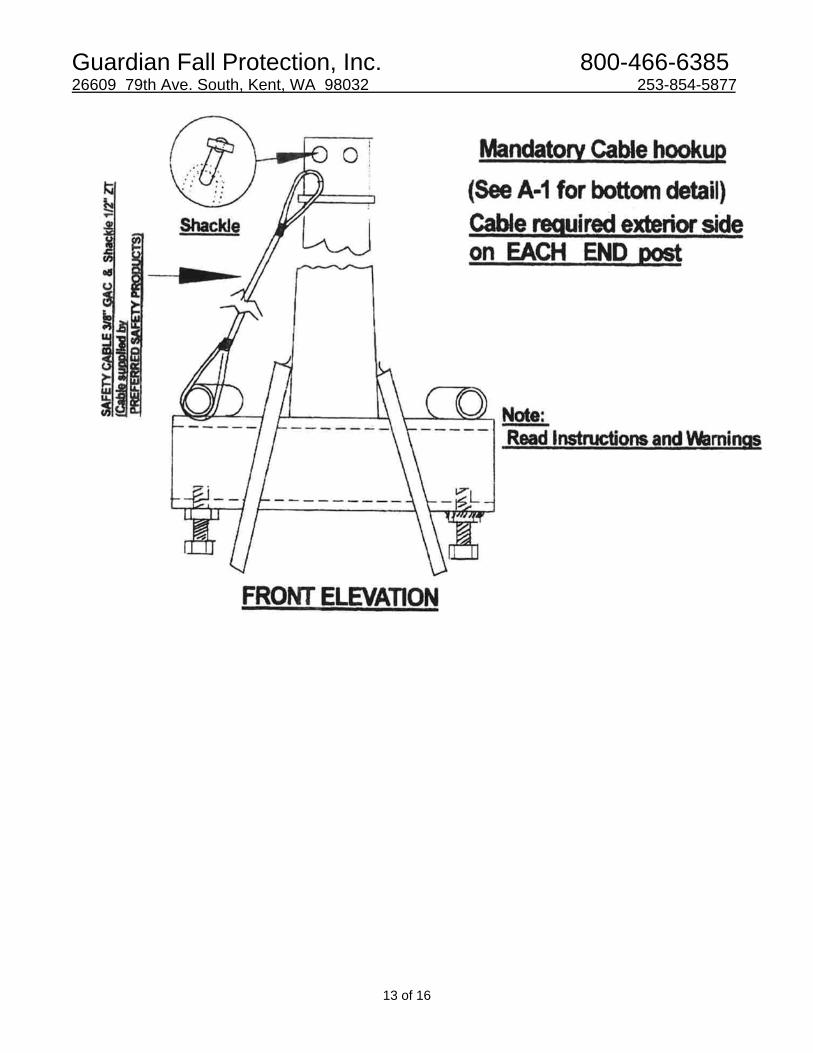
PASS-THRUTM Attachment for BEAMGUARDTM INSTRUCTIONS
General Information: Many erectors would prefer to have a long run of a continuous cable for tie off. Typical would be a bridge project. Many erectors will erect BeamguardsTM on individual beams or girders as they are flown into place, and then later will want to take some of the posts out and allow longer distances between posts and use a continuous cable. Typical would be the girder lines of a large warehouse project. The use of an optional Pass-ThruTM attachment allows the conversion of any BeamguardTM to an intermediate post, and allows a cable to pass by the post without terminating the cable. Then a worker may walk to the post while tied off to the cable, easily move this lanyard hook through the Pass-ThruTM “horns” and keep on walking, while never having to disconnect, and never having to use his second lanyard to maintain 100% fall protection.
Instructions and Warnings 1. Install Pass-ThruTM on any BeamguardTM Post except one that is at the end of a run of
cable. 2. Post spacing is maximum of 60 feet, whether an end post or an intermediate post.
Warning: Depending on height off the ground of the walking surface - closer spacing may be necessary if steel is less than 20 feet high.
3. Intermediate posts do not need to have a side safety cable. If an intermediate post is later
converted back to an end post - by removal of the Pass-ThruTM device and terminating a horizontal cable at the top - then you must use a side safety cable on the outer side.
4. Using the two bolts provided with the Pass-ThruTM (3/8" x 1 ½" w/2 washers and nylon
jamb nut), attach the device to the top of the post. The bent plate at the bottom of the Pass-ThruTM attachment nests exactly on top of the bent plate at the top of the BeamguardTM post. Tighten the bolts snug tight with a wrench.
5. This post is now considered an intermediate post and may NOT be used as an end post or
an anchorage. (Note the two holes on top are filled with the bolts, and therefore there is no longer any place to terminate a cable or attach a lanyard.)
! WARNING !
NEVER, UNDER ANY CIRCUMSTANCES, ATTACH A LANYARD, OR A CABLE END TO THE CURLED OPPOSING “HORNS”
ON THE TOP OF THE PASS-THRUTM ATTACHMENT.
6. After the intermediate posts are set up, and two end posts are ready, attach the cable end
Guardian Fall Protection, Inc. 800-466-6385 26609 79th Ave. South, Kent, WA 98032 253-854-5877
9 of 16
to one end post in the usual manner, pass the cable through the “horns” of the Pass-ThruTM attachment devices, and continue on this way until reaching the next end post. Attach the far end in the usual manner to the top of the end BeamguardTM.
7. Measure the sag distance, according to the chart, in between ONE set of posts. If the
spacing is different, measure between the two posts which make up the longest span. (For instance, if you have 5 posts in a line and the first 3 are spaced at 20 feet and the last two are spaced at 30 feet, measure between posts number 4 and 5 that are spaced at 30 feet.)
8. To measure the sag, push down on the cable between two posts. The cable will become
rigid or taut between the remaining posts and nearly horizontal. Measure the sag from the horizontal under your hand where pressure downwards is being applied. If the sag distance is greater than the chart, you may tighten the cable. If it is less than the chart, you MUST loosen the cable. If you have plenty of clearance below, it is permissible to have more than the prescribed sag. In fact, more sag allows for greater shock absorbency and lower fall forces on the system.
9. Any number of intermediate posts and Pass-ThrusTM can be used in a line. However, we
recommend not more than 300 feet because it will be very difficult to manage more wire rope, and will be quite difficult to get the rope adjusted to have minimum sag.
For instance, if you have 10 “bays” (11 posts spaced 30 feet apart with the middle 9 posts having Pass-ThruTM attachments), you will likely have sag in every bay. If you have 2 or 3 inches in every bay, all the sag will be accumulated at one point during a fall. This is permissible as long as you add the extra amount of pre-sag to the chart, found in the BeamguardTM instructions, to the total fall distance. You can tell how much extra sag you will likely have by pushing down in one bay, as described in 8 above, until the other bays are taut.
10. This system has been tested for two persons falling at one time between two posts. Never
allow more than two persons between two posts. In theory, if one or two persons fell along the end of a long system where there were workers at the other end on the same cable but between two distant posts, it is reasonable to assume that they could not fall at the same time. Therefore, they could be on the same cable, but not between the same two posts as the other persons. Each employer and user must make this assessment for himself asking “How many persons can fall at once on the system?” If the employer chooses to have others on a system who cannot fall at the same time, it must be noted that alternate forms of fall arrest must be available to all the users. Once a fall has occurred, other person(s) on the system should immediately begin using another fall protection system and then get off the elevated surface until the person(s) that fell has been rescued, and the stressed parts of the system have been replaced after a full inspection. Once the new system has been approved for use by the competent person, the new installation can be used for fall protection again.
11. Even though the intermediate posts do not see much strain during a fall (the forces “Pass-
Thru” to the end posts), it is important to have the entire system inspected after a fall to
Guardian Fall Protection, Inc. 800-466-6385 26609 79th Ave. South, Kent, WA 98032 253-854-5877
10 of 16
assure there is no damage to any part of the system. Any part that is stressed should be replaced or sent to Guardian Fall Protection for inspection and replacement.
12. Read the full instructions and warnings that come with the BeamguardTM or in addition to
these instructions and warnings. Read all labels. If labels are missing or unreadable, call for replacements. Call 1-800-466-6385 for information and questions. This is a free call.
© 2001 - Patent US 6,173,809 B1 - Other Patents Pending
Guardian Fall Protection, Inc. 800-466-6385 26609 79th Ave. South, Kent, WA 98032 253-854-5877
11 of 16

Guardian Fall Protection, Inc. 800-466-6385 26609 79th Ave. South, Kent, WA 98032 253-854-5877
12 of 16
Guardian Fall Protection, Inc. 800-466-6385 26609 79th Ave. South, Kent, WA 98032 253-854-5877
13 of 16
Guardian Fall Protection, Inc. 800-466-6385 26609 79th Ave. South, Kent, WA 98032 253-854-5877
14 of 16
Guardian Fall Protection, Inc. 800-466-6385 26609 79th Ave. South, Kent, WA 98032 253-854-5877
15 of 16
Guardian Fall Protection, Inc. 800-466-6385 26609 79th Ave. South, Kent, WA 98032 253-854-5877
16 of 16
NOTES