Embed Size (px)
Citation preview
Forum for Electromagnetic Research Methods and Application Technologies (FERMAT)
Beam-shaping Technology Based on Generalized Laws of Refraction and
Reflection
Pengfei Zhang 1*, Raj Mittra2, 3 and and Shuxi Gong1 1 Collaborative Innovation Center of Inf. Sensing & Understanding,
Xidian University, Xi’an Shaanxi, 710071, China 2EMC Lab, University of Central Florida, Orlando, FL 32816 USA
3King Abdulaziz University, Jeddah 22254, Saudi Arabia *Email: [email protected]
Abstract: The generalized Snell’ law is developed and modified for curved surface, and
also the generalized GO. Based on which, we present a new beamshaping technology
using the flat lens consists of phase shift structure (PSS), which can reshape the primary
beam to that with arbitrary desired shape. The design procedure of the beamshaping flat
lens (BSFL) is discussed in detail. Several examples are given to verify the method.
Moreover, some potential applications are proposed.
Keywords: Beam shaping; Generalized Laws of Reflection and Refraction; Flat Lens.
References: [1] Nanfang Yu, Patrice Genevet, Mikhail A. Kats etc. Light Propagation with Phase
Discontinuities: Generalized Laws of Reflection and Refraction, SCIENCE 2011,224(6054):333-337.
[2] N Yu , F Capasso. Flat optics with designer metasurfaces , Nature Materials, 2014, 13(2):139-50.
[3] N. Gagnon, A. Petosa and D.A. McNamara, "Thin Microwave Phase-Shifting Surface (PSS) Lens Antenna Made of Square Elements," IET Electronics Letters, vol. 46, no. 5, March, p.327-329, 2010
[4] H. Ling, R. C. Chow, and S. W. Lee, “Shooting and bouncing rays: Calculating the RCS of an arbitrarily shaped cavity,” IEEE Trans. Antennas Propag., vol. 37, no. 2, pp. 194-205, 1989.
ZHANG Pengfei was born in 1979 in Shanxi China. He received B.S. degree, M.S. degree, and Ph.D. degree in Electromagnetic field and Microwave Technology from Xidian University, in 2001, 2006, and 2008, respectively. In 2007, he joined the National Laboratory of Science and Technology on Antennas and Microwaves, and worked as an associate professor in this lab from 2009. This work was partly carried out when Penfei Zhang was at the University of Central Florida as a Chinese Scholarship Council (CSC) Scholar on leave from National Key Laboratory of antenna and Microwave Technology. His research and development interests include the design of lens antenna, prediction and
control of Radar cross section (RCS), the design of water antennas, electromagnetic analysis and electromagnetic calculation. He is the author of over 20 referred journal and conference papers on these topics.
Shu-Xi Gong received the B.S. and M.S. degrees from Xidian University, Xi’an, China, in 1982 and 1984, respectively, and the Ph.D. degree from Xi’an Jiao Tong University, Xi’an, in 1988. He is currently a full Professor and Director of the National Key Laboratory of Science and Technology on Antennas and Microwaves. His research interests include antenna theory and technology, prediction and control of antenna RCS, and RCS calculation of complex targets. He has authored or coauthored over 200 refereed journal papers. He has also authored Principles of Generalized Eigen function
Expansions in Electromagnetic Theory (Xi’an: Xidian Univ. Press, 2010), Prediction and Reduction of Antenna Radar Cross Section (Xi’an: Xidian Univ. Press, 2010), and Antennas for Mobile Communication Systems (Beijing: Electronics Industry Press, 2011). Dr. Gong is a Senior Member of Chinese Institute of Electronics (CIE) and Vice Chairman of the Antenna Society of CIE. He is an Editorial Board Member of Chinese Journal of Xidian University and Journal of Microwaves. He was a recipient of the Science and Technology Advancement Award of Shaanxi Province, the Science and Technology Advancement Award of the Ministry of Information Industry of China, the Yilida Best Paper Award of Chinese Journal of Radio Sicence, the Outstanding Young Scholar Award of the Ministry of Mechanical Electronics of China, and the Excellent Young Backbone Teacher Award of the National Education Committee of China.
Raj Mittra is a Professor in the Department of Electrical Engineering & Computer Science department of the University of Central Florida in Orlando, FL., where he is the Director of the Electromagnetic Communication Laboratory. Prior to joining the University of Central Florida, he worked at Penn State as a Professor in the Electrical and Computer Engineering from 1996 through June, 2015. He was a Professor in the Electrical and
Computer Engineering at the University of Illinois in Urbana Champaign from 1957 through 1996, when he moved to the Penn State University. Currently, he also holds the position of Hi-Ci Professor at King Abdulaziz University in Saudi Arabia, He is a Life Fellow of the IEEE, a Past-President of AP-S, and he has served as the Editor of the Transactions of the Antennas and Propagation Society. He won the Guggenheim Fellowship Award in 1965, the IEEE Centennial Medal in 1984, and the IEEE Millennium medal in 2000. Other honors include the IEEE/AP-S Distinguished Achievement Award in 2002, the Chen-To Tai Education Award in 2004 and the IEEE Electromagnetics Award in 2006, and the IEEE James H. Mulligan Award in 2011. Recently he founded the e-Journal FERMAT (www.e-fermat.org) and has been serving as the co-editor-in-chief of the same. Dr. Mittra is a Principal Scientist and President of RM Associates, a consulting company founded in 1980, which provides services to industrial and governmental organizations, both in the U.S. and abroad.
*This use of this work is restricted solely for academic purposes. The author of this work owns the copyright and no reproduction in any form is permitted without written permission by the author.*
Beam-shaping Technology Based on Generalized Laws of
Refraction and ReflectionPengfei Zhang , Raj Mittra and Shuxi Gong
1. Collaborative Innovation Center of Inf. Sensing & Understanding, Xidian University, Xi’an Shaanxi, 710071, China
2. EMC Lab, University of Central Florida, Orlando, FL 32816 USA3. King Abdulaziz University, Jeddah 22254, Saudi Arabia
*Email: [email protected]
1,2* 2,3 1
SLIDE /391
2Location of the two Universities
SLIDE /39
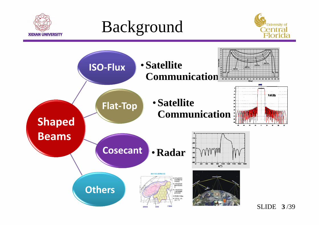
Background
ISO‐Flux • Satellite Communication
Flat‐Top • Satellite Communication
Cosecant • Radar
Shaped Beams
Others3SLIDE /39
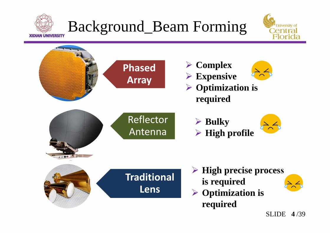
Background_Beam Forming
Beam Shaping
Others
Phased Array
Reflector Antenna
Complex Expensive Optimization is
required
Bulky High profile
Traditional Lens
High precise process is required
Optimization is required
4SLIDE /39
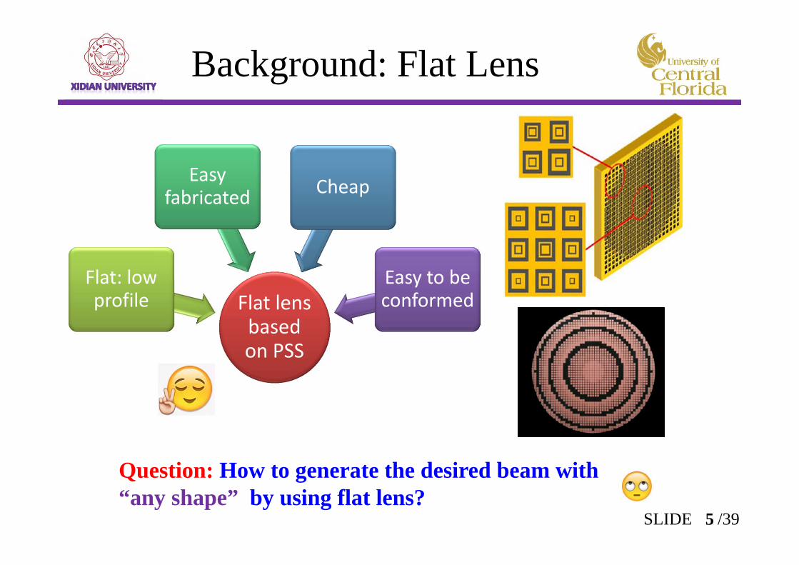
Background: Flat Lens
Beam Shaping
Others
Flat lens based on PSS
Flat: low profile
Easy fabricated Cheap
Easy to be conformed
Question: How to generate the desired beam with “any shape” by using flat lens?
5SLIDE /39
Generalized Snell’ Law and GOGeneralized Snell’ Laws ;Generalized GO; Some special cases.
Beam Shaping Based on Flat lensPrinciple of the beam shaping;Design of lens based on PSS .
Examples:Far region: Flat_Top /ISO_Flux /High Gain patterns; Near region: Point Focus/Circular Ring focus.
Potential application and future work
Outline
Target: Provide a method
which can generate the desired beams with arbitrary shapes.
The method should be intuitively in concept and avoid using optimization methods.
6SLIDE /39
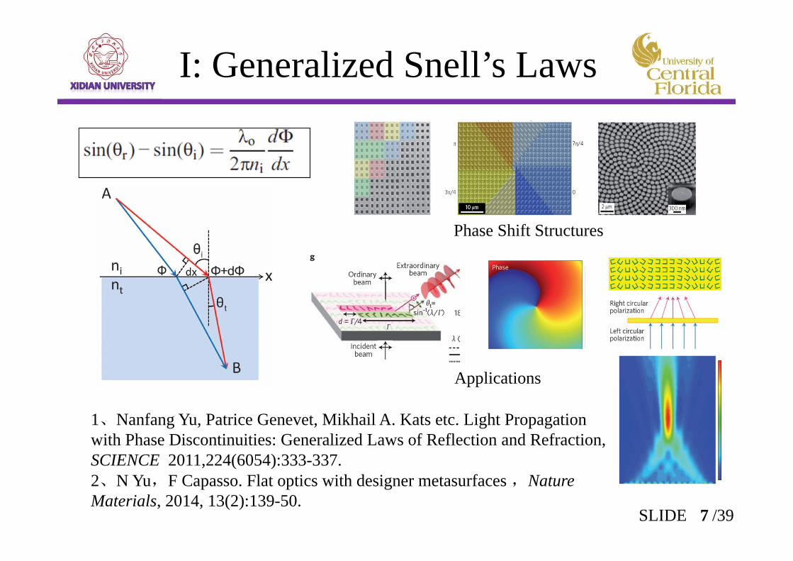
I: Generalized Snell’s Laws
1、Nanfang Yu, Patrice Genevet, Mikhail A. Kats etc. Light Propagation with Phase Discontinuities: Generalized Laws of Reflection and Refraction,SCIENCE 2011,224(6054):333-337.2、N Yu,F Capasso. Flat optics with designer metasurfaces ,Nature Materials, 2014, 13(2):139-50.
Phase Shift Structures
7SLIDE /39
Applications
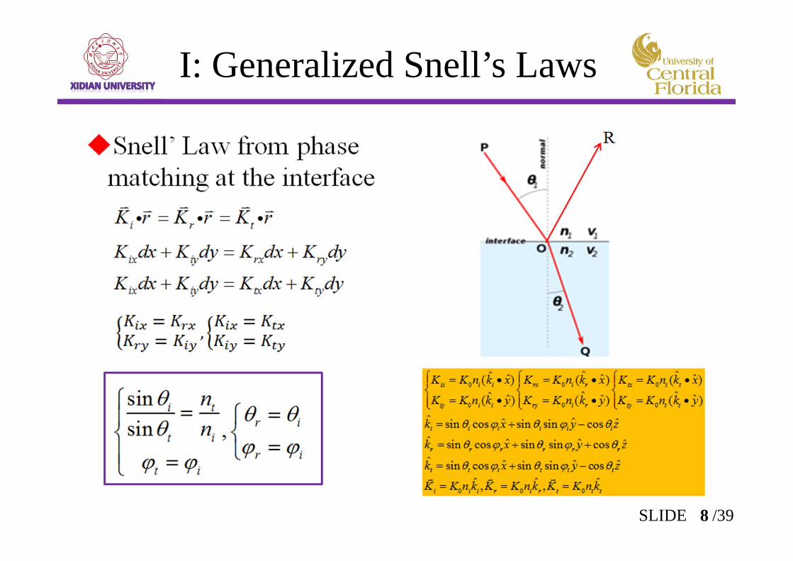
I: Generalized Snell’s Laws
8SLIDE /39
( )( )
i r r
i t t
K r r K r
K r r K r
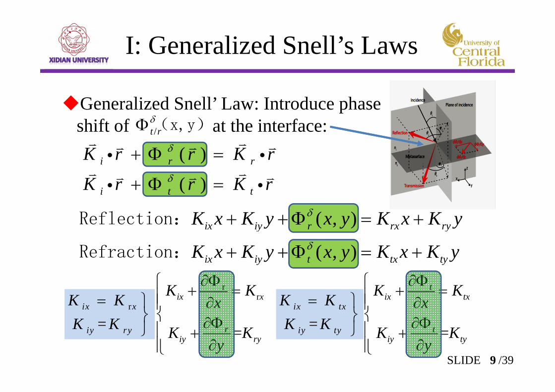
I: Generalized Snell’s Laws
Generalized Snell’ Law: Introduce phase shift of at the interface:/t r
(x,y)
rr
= =
tix x ix tx
r tiy ry iy ty
K K K Kx x
K K K Ky y
( , )
( , )ix iy r rx ry
ix iy t tx ty
K x K y x y K x K y
K x K y x y K x K y
Reflection:
Refraction:
9SLIDE /39
r
=ix x
iy ry
K KK K
=
ix tx
iy ty
K KK K
I: Generalized Snell’s Laws
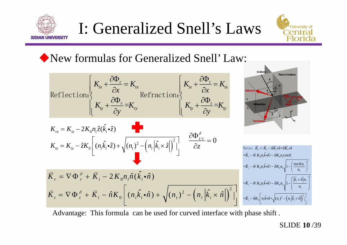
New formulas for Generalized Snell’ Law:
0
22
0
ˆˆ ˆ2 ( )
ˆ ˆˆ ˆ ˆ( ) ( )
r r i i i
t t i i i t i i
K K K n n k n
K K nK n k n n n k n
/ 0t r
z
0
22
0
ˆˆ ˆ2 ( )
ˆ ˆˆ ˆ ˆ( ) ( )
rz iz i i
tz iz i i t i i
K K K n z k z
K K zK n k z n n k z
Advantage: This formula can be used for curved interface with phase shift .
rr
= =
tix x ix tx
r tiy ry iy ty
K K K Kx x
K K K Ky y
Reflection: Refraction:
10SLIDE /39
t
0 0 t
2
i0 0
2
0 0
22
0
ˆ ˆ ˆ ˆ+ˆˆ ˆ ˆ= cos
sinˆˆ ˆ ˆ= 1
ˆ ˆˆˆ ˆ ˆ= 1
ˆ ˆˆ ˆ ˆ= + ( )
t i i
i i t
ii i t
t
i ii i t
t
i i t i i
K K nK n nK n
K n K n k n nK n
nK n K n k n nK nn
k n nK n K n k n nK n
n
K nK n k n n n k n
Note:
( )
( )
( )
I: Generalized Snell’s Laws
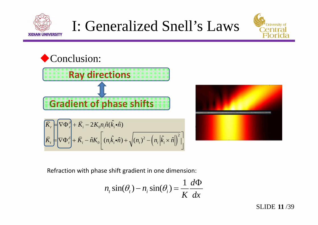
Conclusion:Ray directions
Gradient of phase shifts
0
22
0
ˆˆ ˆ2 ( )
ˆ ˆˆ ˆ ˆ( ) ( )
r r i i i
t t i i i t i i
K K K n n k n
K K nK n k n n n k n
Refraction with phase shift gradient in one dimension:
1sin( ) sin( )t t i idn n
K dx
11SLIDE /39
I: Generalized Snell’s Laws
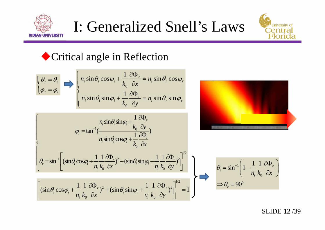
Critical angle in Reflection
r i
r i
0
0
1sin cos sin cos
1sin sin sin sin
ri i i i r r
ri i i i r r
n nk x
n nk y
1 0
01/2
1 2 2
0 0
1sin sintan ( )1sin cos
1 1 1 1sin (sin cos ) (sin sin )
ri i i
rr
i i i
r rr i i i i
i i
nk y
nk x
n k x n k y
1/22 2
0 0
1 1 1 1(sin cos ) (sin sin ) 1r ri i i i
i in k x n k y
1
0
1 1sin 1
90
ri
i
or
n k x
12SLIDE /39
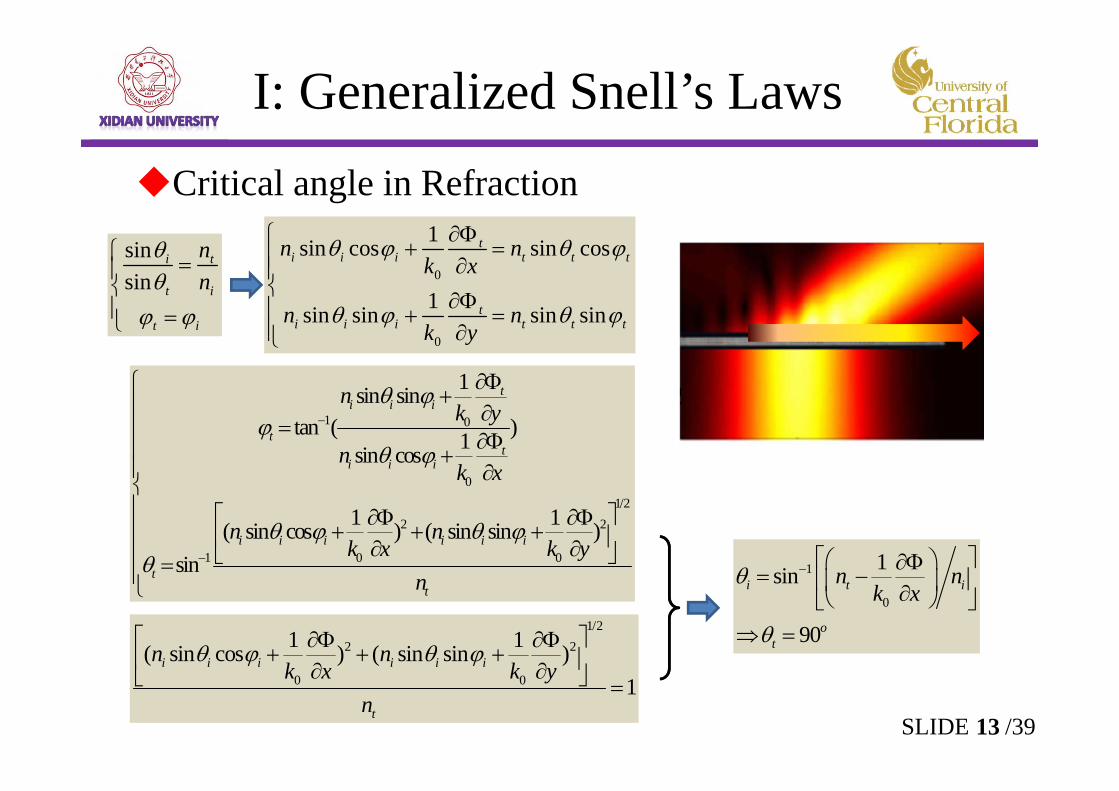
Critical angle in Refraction
sinsin
i t
t i
t i
nn
0
0
1sin cos sin cos
1sin sin sin sin
ti i i t t t
ti i i t t t
n nk x
n nk y
1 0
01/2
2 2
1 0 0
1sin sintan ( )1sin cos
1 1( sin cos ) ( sin sin )sin
ti i i
tt
i i i
i i i i i i
tt
nk y
nk x
n nk x k y
n
1/2
2 2
0 0
1 1( sin cos ) ( sin sin )1
i i i i i i
t
n nk x k y
n
1
0
1sin
90
i t i
ot
n nk x
13SLIDE /39
I: Generalized Snell’s Laws
I: Generalized GO
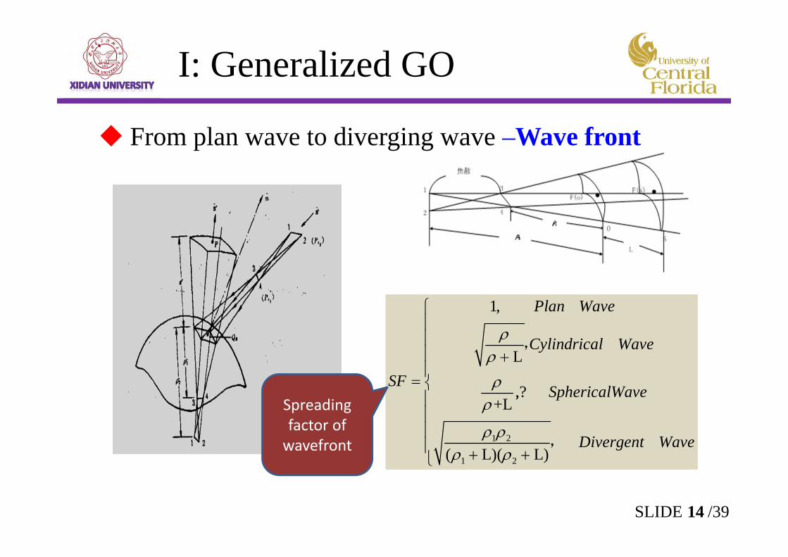
From plan wave to diverging wave –Wave front
1 2
1 2
1,
L
,?,+L
( L)( L)
Plan Wave
Cylindrical Wave
SFSphericalWave
Divergent Wave
,
,
14SLIDE /39
Spreading factor of wavefront
11 12 1 1 1 2
21 11 2 1 2 2
ˆ ˆ ˆ ˆˆ ˆ ˆ ˆ
i i i s i s
i i i s i s
p p x x x xp p x x x x
11 12 1 1 1 2
21 11 2 1 2 2
ˆ ˆ ˆ ˆˆ ˆ ˆ ˆ
r r r s r s
r r r s r s
p p x x x xp p x x x x
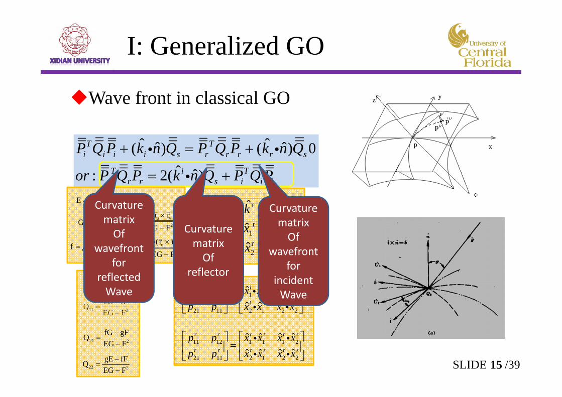
Wave front in classical GO
ˆ ˆˆ ˆ( ) ( ) 0ˆ ˆ: 2( )
T Ti i i i s r r r r s
T i Tr r r s i i i
P Q P k n Q P Q P k n Q
or P Q P k n Q P Q P
1
2
ˆ
ˆˆ
i
i
i
kxx
1
2
n̂ˆˆ
s
s
xx
u vF r r
11 2eG fFQEG F
15SLIDE /39
I: Generalized GO
1
2
ˆ
ˆˆ
i
i
i
kxx
r
r1r2
ˆ
ˆˆ
kxx
1
2
n̂ˆˆ
s
s
xx
u uE r r u vF r r
v vG r r uu u v2
r (r r )eEG F
uv u v2
r (r r )fEG F
vv u v2
r (r r )gEG F
11 2eG fFQEG F
21 2
fG gFQEG F
22 2
gE fFQEG F
Curvature matrixOf
wavefrontfor
incident Wave
Curvature matrixOf
reflector
Curvature matrixOf
wavefrontfor
reflected Wave
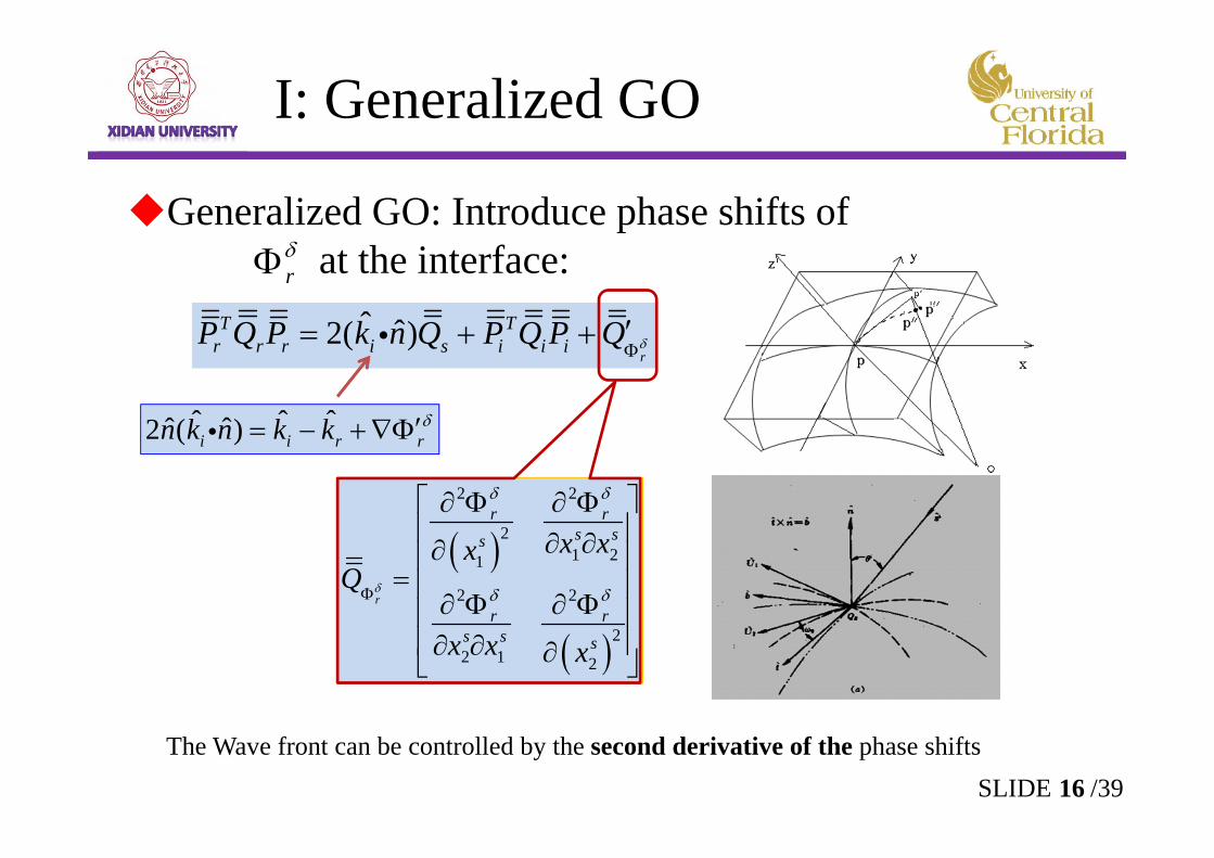
The Wave front can be controlled by the second derivative of the phase shifts
Generalized GO: Introduce phase shifts of at the interface:
ˆ ˆ2( )r
T Tr r r i s i i iP Q P k n Q P Q P Q
2 2
21 21
2 2
22 1 2
r
r rs ss
r rs s s
x xxQ
x x x
r
ˆ ˆ ˆˆ ˆ2 ( )i i r rn k n k k
16SLIDE /39
I: Generalized GO
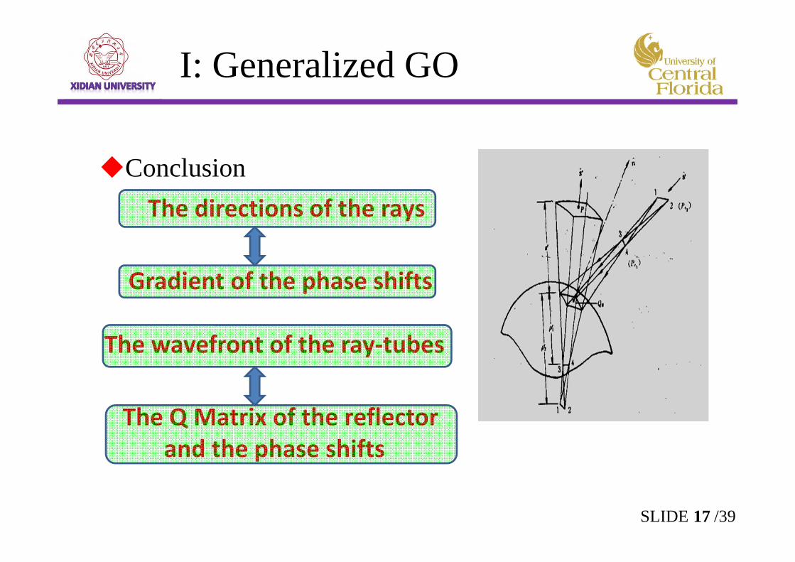
ConclusionThe directions of the rays
Gradient of the phase shifts
The wavefront of the ray‐tubes
The Q Matrix of the reflector and the phase shifts
17SLIDE /39
I: Generalized GO
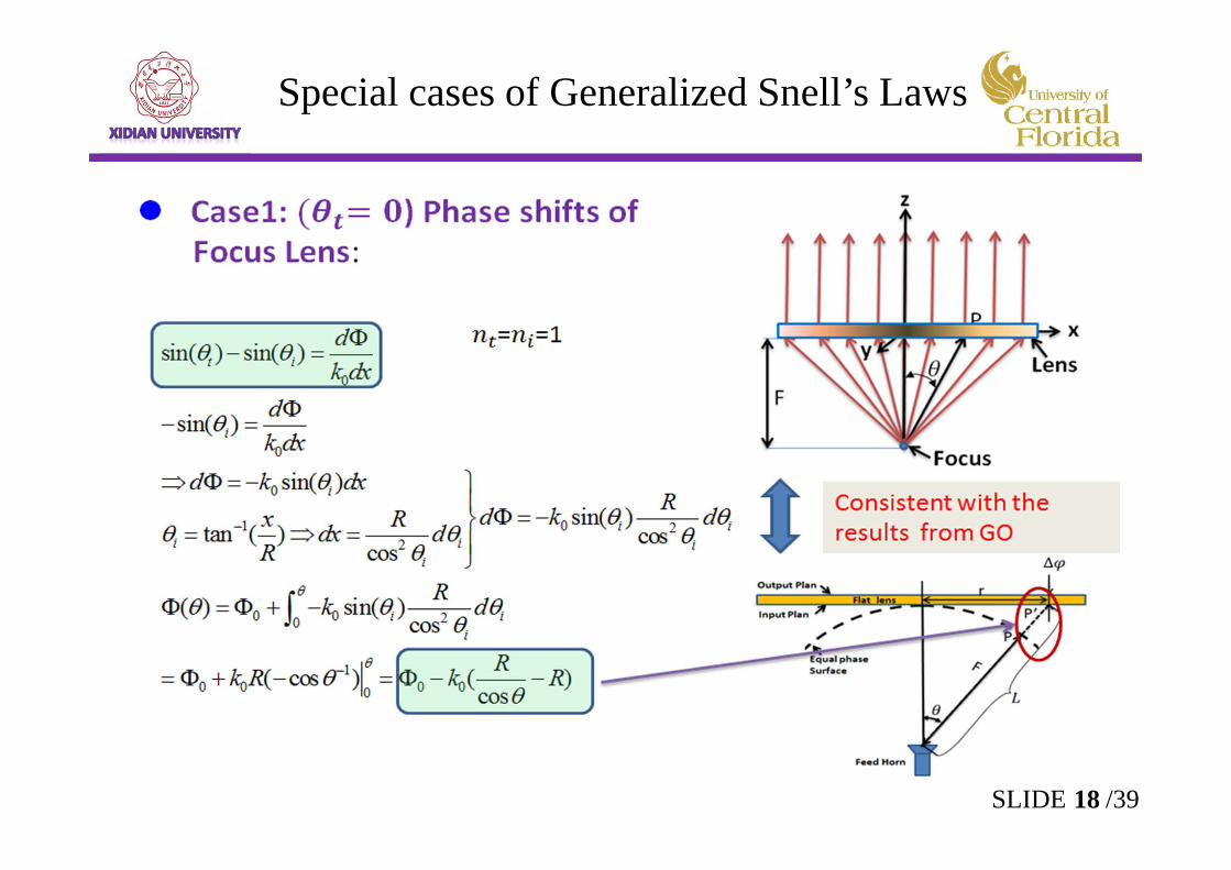
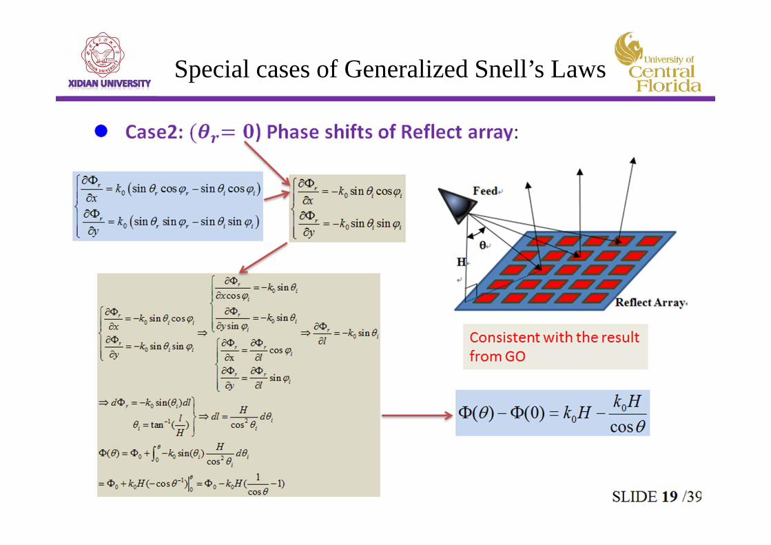
Special cases of Generalized Snell’s Laws
18SLIDE /39
Special cases of Generalized Snell’s Laws
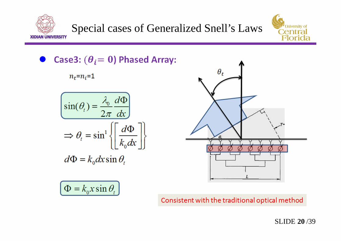
20SLIDE /39
Special cases of Generalized Snell’s Laws
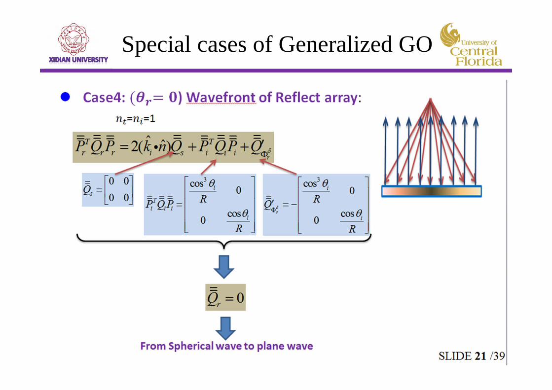
Special cases of Generalized GO
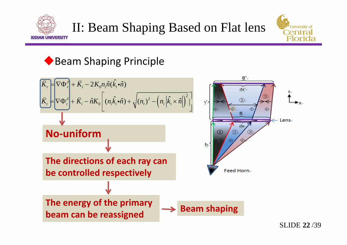
II: Beam Shaping Based on Flat lens
Beam Shaping Principle
0
22
0
ˆˆ ˆ2 ( )
ˆ ˆˆ ˆ ˆ( ) ( )
r r i i i
t t i i i t i i
K K K n n k n
K K nK n k n n n k n
No‐uniform
The directions of each ray can be controlled respectively
The energy of the primary beam can be reassigned Beam shaping
22SLIDE /39
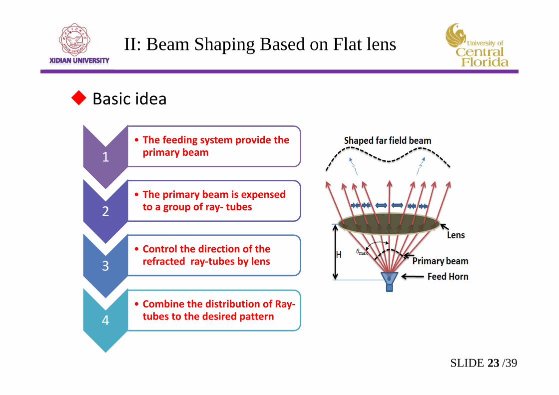
II: Beam Shaping Based on Flat lens
1• The feeding system provide the primary beam
2• The primary beam is expensed to a group of ray‐ tubes
3• Control the direction of the refracted ray‐tubes by lens
4• Combine the distribution of Ray‐tubes to the desired pattern
Basic idea
23SLIDE /39
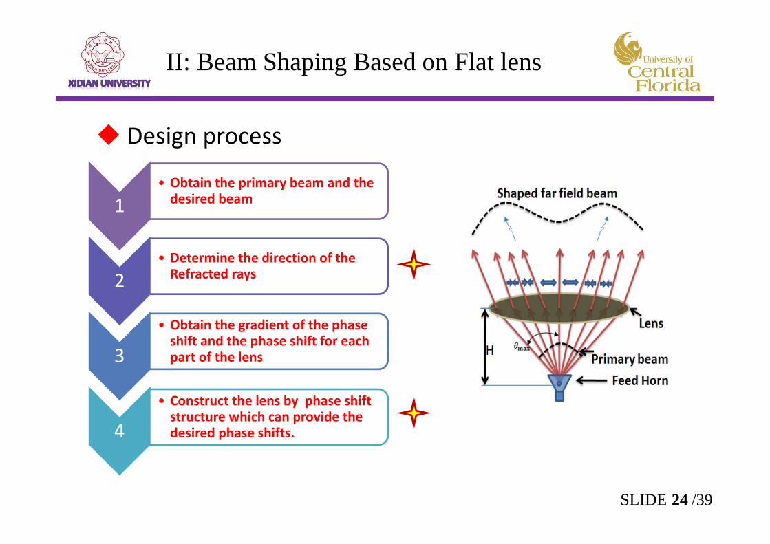
II: Beam Shaping Based on Flat lens
1• Obtain the primary beam and the desired beam
2• Determine the direction of the Refracted rays
3
• Obtain the gradient of the phase shift and the phase shift for each part of the lens
4• Construct the lens by phase shift structure which can provide the desired phase shifts.
Design process
24SLIDE /39
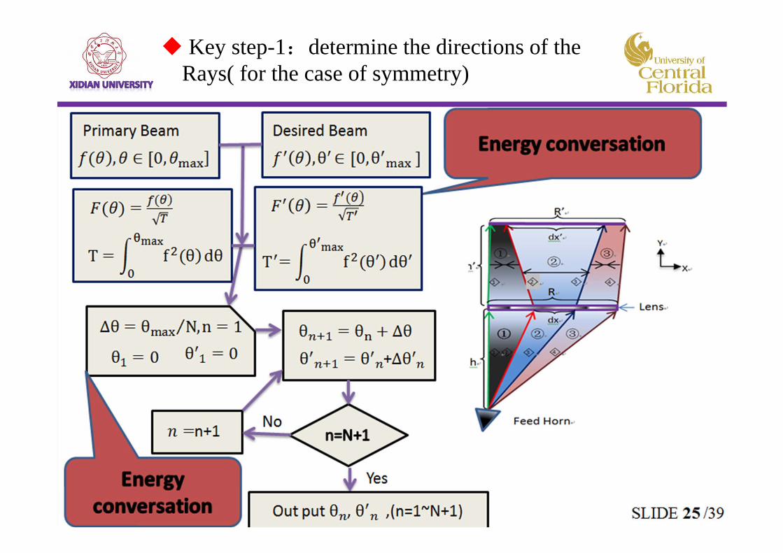
Key step-1:determine the directions of the Rays( for the case of symmetry)
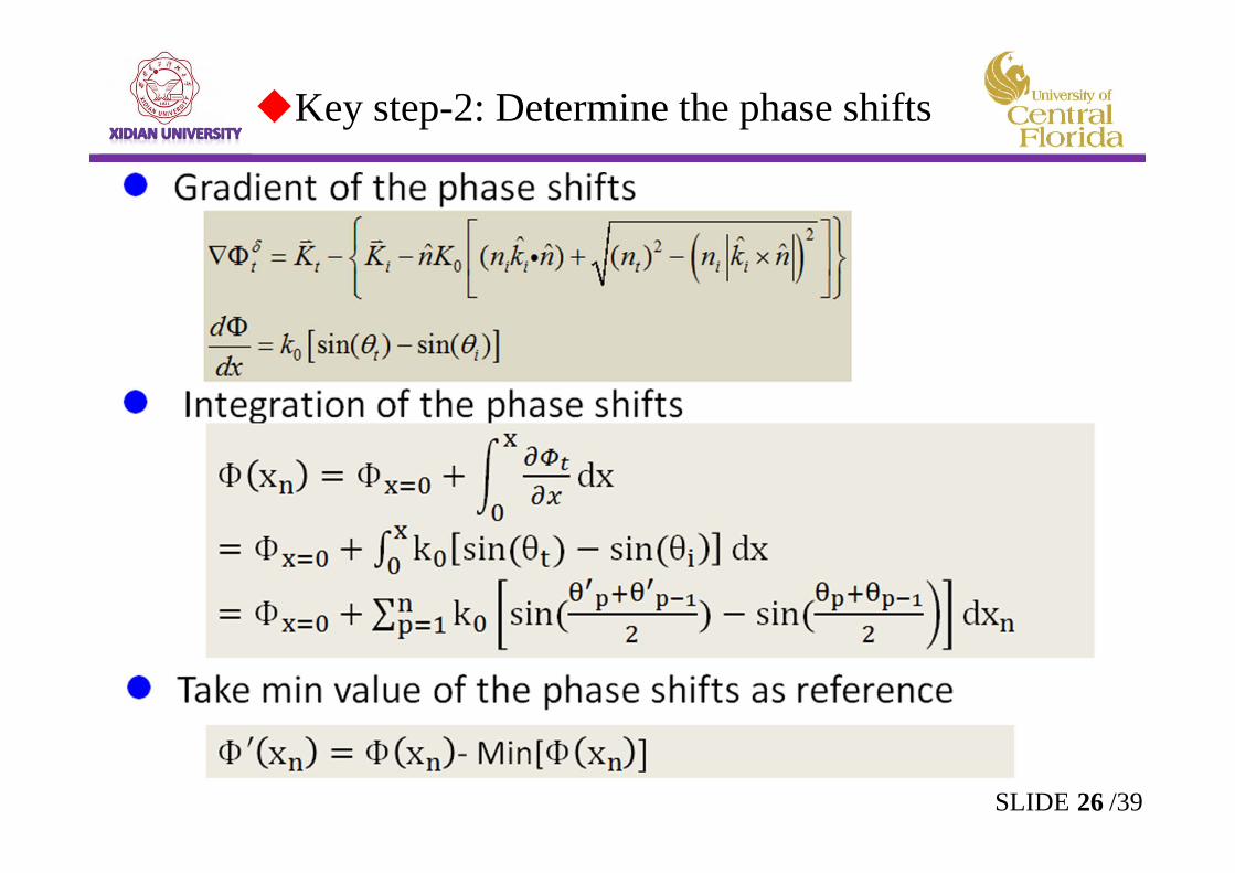
Key step-2: Determine the phase shifts
26SLIDE /39
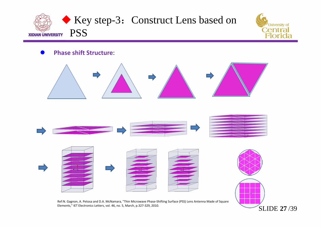
Key step-3:Construct Lens based on PSS
Ref:N. Gagnon, A. Petosa and D.A. McNamara, "Thin Microwave Phase‐Shifting Surface (PSS) Lens Antenna Made of Square Elements," IET Electronics Letters, vol. 46, no. 5, March, p.327‐329, 2010.
Phase shift Structure:
27SLIDE /39
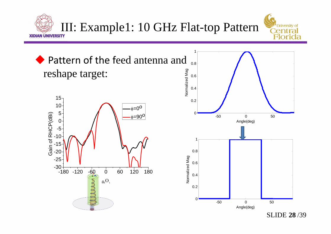
III: Example1: 10 GHz Flat-top Pattern
Pattern of the feed antenna and reshape target:
-180 -120 -60 0 60 120 180-30-25-20-15-10-505
1015
Gai
n of
RH
CP(
dBi)
=0o
=90o -50 0 500
0.2
0.4
0.6
0.8
1
Nor
mal
ized
Mag
Angle(deg)
-50 0 500
0.2
0.4
0.6
0.8
1
Nor
mal
ized
Mag
Angle(deg)
28SLIDE /39
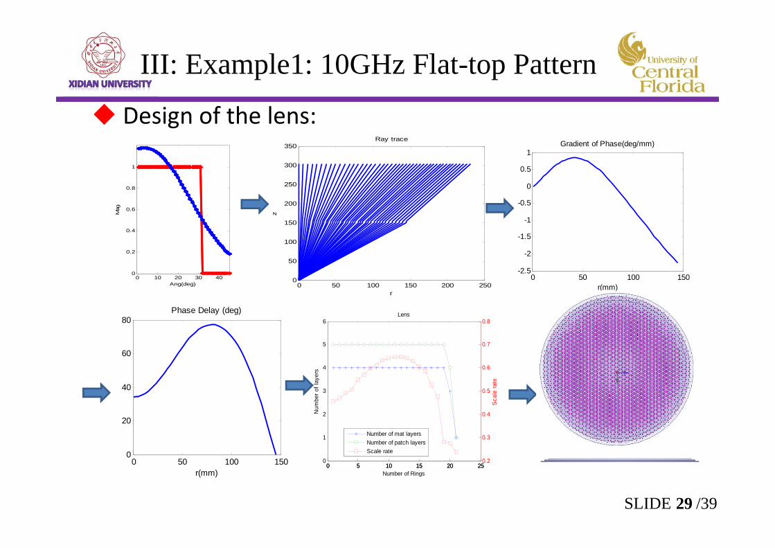
Design of the lens:
0 10 20 30 400
0.2
0.4
0.6
0.8
1
Mag
Ang(deg) 0 50 100 150 200 2500
50
100
150
200
250
300
350
z
r
Ray trace
0 50 100 150-2.5
-2
-1.5
-1
-0.5
0
0.5
1
r(mm)
Gradient of Phase(deg/mm)
0 50 100 1500
20
40
60
80
r(mm)
Phase Delay (deg)
0 5 10 15 20 250
1
2
3
4
5
6N
umbe
r of l
ayer
s
Number of Rings
Lens
0 5 10 15 20 250.2
0.3
0.4
0.5
0.6
0.7
0.8
Sca
le ra
te
Number of mat layersNumber of patch layersScale rate
III: Example1: 10GHz Flat-top Pattern
29SLIDE /39
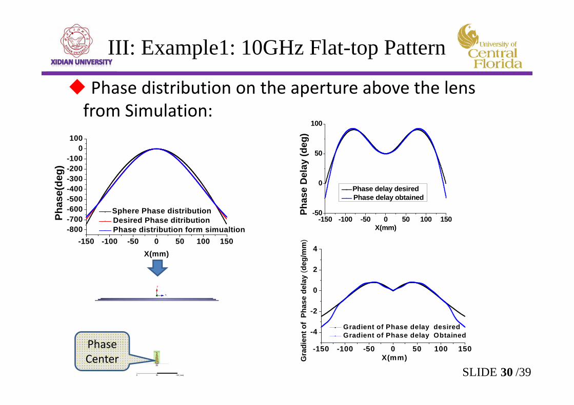
Phase distribution on the aperture above the lens from Simulation:
III: Example1: 10GHz Flat-top Pattern
-150 -100 -50 0 50 100 150-800-700-600-500-400-300-200-100
0100
Phas
e(de
g)
X(mm)
Sphere Phase distribution Desired Phase ditribution Phase distribution form simualtion
-150 -100 -50 0 50 100 150-50
0
50
100
Phas
e D
elay
(deg
)
X(mm)
Phase delay desired Phase delay obtained
-150 -100 -50 0 50 100 150
-4
-2
0
2
4
Gra
dien
t of
Phas
e de
lay
(deg
/mm
)
X(mm)
Gradient of Phase delay desired Gradient of Phase delay Obtained
30SLIDE /39
Phase Center
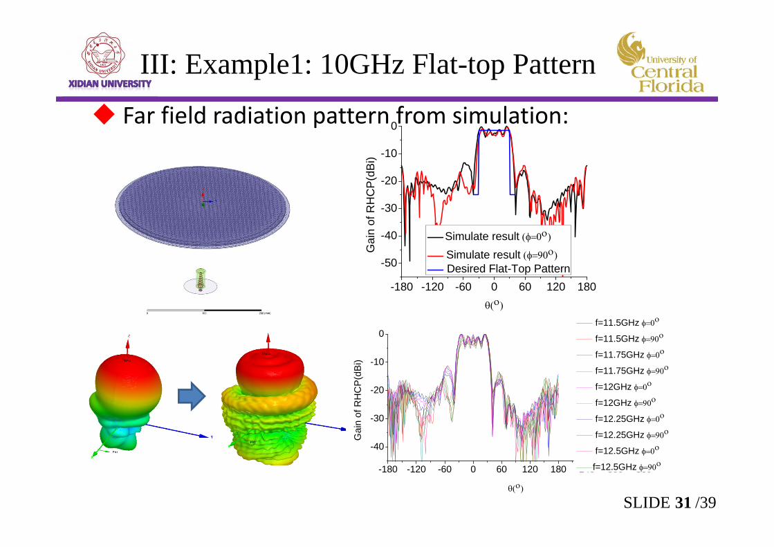
Far field radiation pattern from simulation:
-180 -120 -60 0 60 120 180
-50
-40
-30
-20
-10
0
Gai
n of
RH
CP(
dBi)
Simulate result Simulate result Desired Flat-Top Pattern
-180 -120 -60 0 60 120 180 240 300 360
-40
-30
-20
-10
0
Gai
n of
RH
CP(
dBi)
f=11.5GHz
f=11.5GHz
f=11.75GHz
f=11.75GHz
f=12GHz
f=12GHz
f=12.25GHz
f=12.25GHz
f=12.5GHz
f=12.5GHz
III: Example1: 10GHz Flat-top Pattern
31SLIDE /39
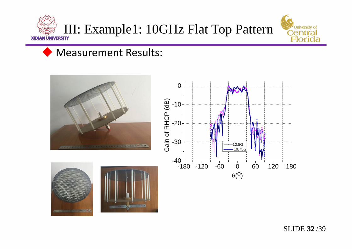
Measurement Results:
-180 -120 -60 0 60 120 180-40
-30
-20
-10
0
Gai
n of
RH
CP
(dB)
(o)
10.5G 10.75G
32SLIDE /39
III: Example1: 10GHz Flat Top Pattern
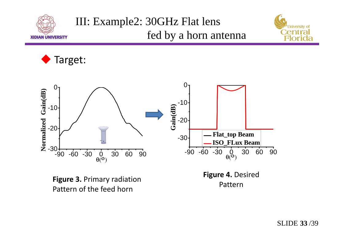
Target:
-90 -60 -30 0 30 60 90-30
-20
-10
0
Nor
mal
ized
Gai
n(dB
)
-90 -60 -30 0 30 60 90
-30
-20
-10
0
Gai
n(dB
)
Flat_top Beam ISO_FLux Beam
Figure 3. Primary radiation Pattern of the feed horn
Figure 4. Desired Pattern
33SLIDE /39
III: Example2: 30GHz Flat lensfed by a horn antenna
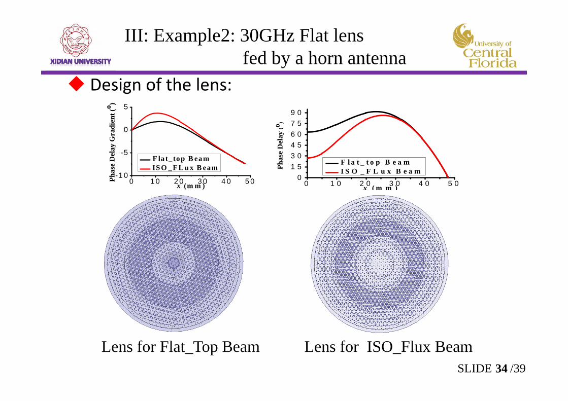
Design of the lens:
0 1 0 2 0 3 0 4 0 5 0-1 0
-5
0
5Ph
ase
Del
ay G
radi
ent (
o )
x (m m )
F la t_ top B eam IS O _F L u x B eam
0 1 0 2 0 3 0 4 0 5 00
1 53 04 56 07 59 0
Phas
e D
elay
(o )
x ( m m )
F l a t _ t o p B e a m I S O _ F L u x B e a m
Lens for Flat_Top Beam Lens for ISO_Flux Beam
III: Example2: 30GHz Flat lensfed by a horn antenna
34SLIDE /39
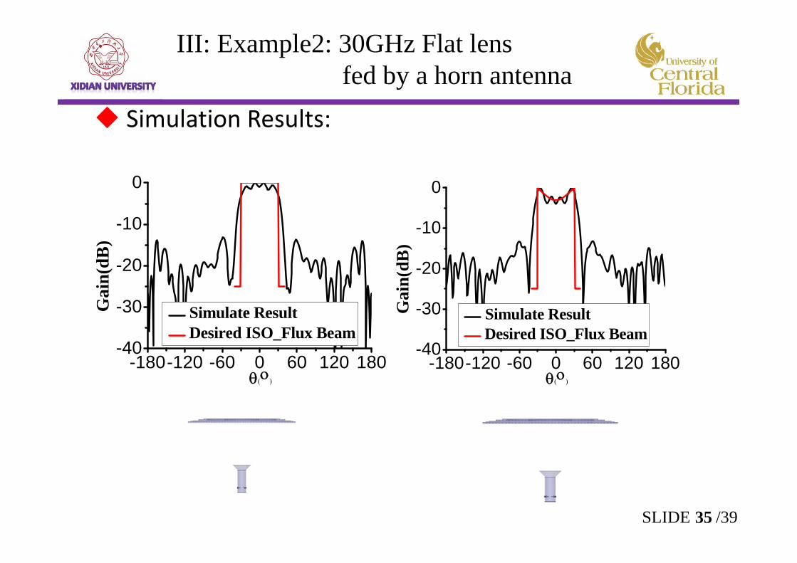
Simulation Results:
-180-120 -60 0 60 120 180-40
-30
-20
-10
0
Gai
n(dB
)
Simulate Result Desired ISO_Flux Beam
-180-120 -60 0 60 120 180-40
-30
-20
-10
0
Gai
n(dB
)
Simulate Result Desired ISO_Flux Beam
III: Example2: 30GHz Flat lensfed by a horn antenna
35SLIDE /39
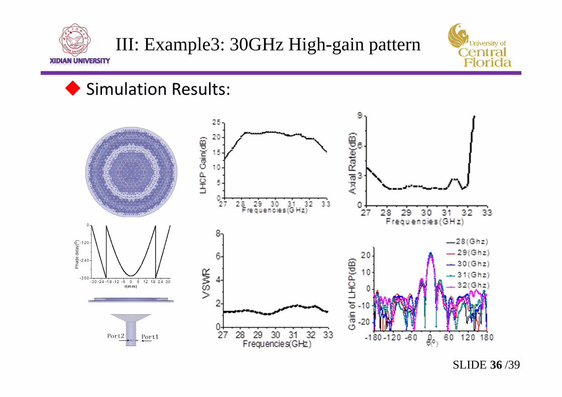
Simulation Results:
III: Example3: 30GHz High-gain pattern
36SLIDE /39
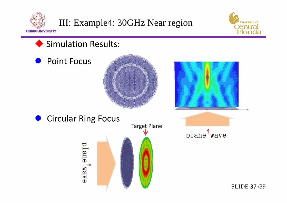
Simulation Results:
Point Focus
Circular Ring Focus
III: Example4: 30GHz Near region
Target Plane
37SLIDE /39
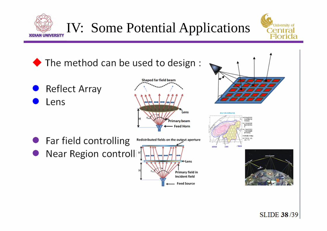
IV: Some Potential Applications
Summary
Generalized Snell’s law is developed and modified for curved surface. GO is also generalized.A new beam-shaping technology using the flat lens
has been presented.A PSS which can be used for CP is proposed and
used in lens design.Several examples are given to verify the method.
Some potential applications are proposed.
39SLIDE /39