Embed Size (px)
Citation preview
Wir schaffen Wissen – heute für morgen
,
Beam shaping
M.Divall
SwissFEL
LA3NET school
15/10/2012
• Introduction to laser applications in FEL
• Laser beam transport – basic optics/ rays/ transfer matrix
– Image relay
– Gaussian beam
– Ray-tracing softwares
– Waves vs. rays, physical optics
• Why is shaping important? – Gaussian vs. real beams
– Emittance optimization
• Transverse shaping – Spatial filters
– Refractive beam-shapers optics
– Adaptive optics
– Hard aperture
• Longitudinal shaping – Time domain methods
– Frequency domain methods
• Safety
Outline
LA3NET school, GANIL, Caen, 15th October 2012 M.Divall (PSI)
SwissFEL
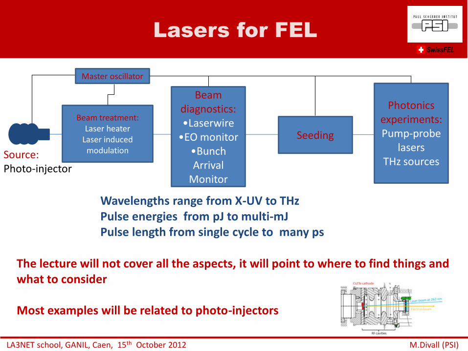
Lasers for FEL
Beam treatment: Laser heater
Laser induced modulation
Beam diagnostics: •Laserwire
•EO monitor •Bunch Arrival
Monitor
Seeding
Photonics experiments: Pump-probe
lasers THz sources
Source: Photo-injector
Wavelengths range from X-UV to THz Pulse energies from pJ to multi-mJ Pulse length from single cycle to many ps
The lecture will not cover all the aspects, it will point to where to find things and what to consider Most examples will be related to photo-injectors
LA3NET school, GANIL, Caen, 15th October 2012 M.Divall (PSI)
SwissFEL
Master oscillator
ADVANTAGES
Capability to synchronize to external RF source with very high accuracy
Flexibility for timing structure, single pulse operation
Size, shape, pulselength, energy can be optimized for machine
Can produce polarized electrons
Gives smaller transverse emittance
No energy tails
No satellites
Thermionic gun
Photo-injector
Photo-injector SwissFEL
LA3NET school, GANIL, Caen, 15th October 2012 M.Divall (PSI)
K. Floettman DESY
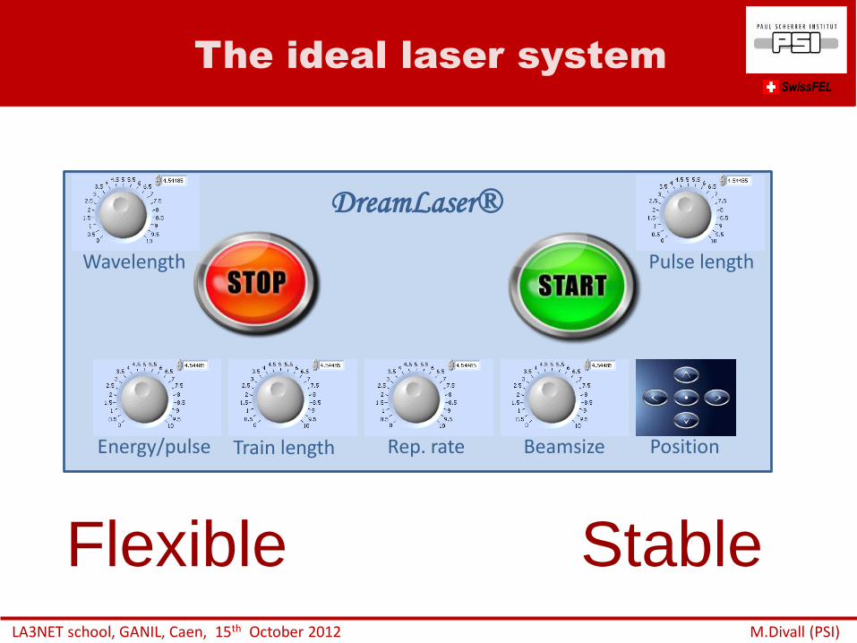
The ideal laser system
LA3NET school, GANIL, Caen, 15th October 2012 M.Divall (PSI)
Energy/pulse Train length Rep. rate Beamsize Position
Wavelength Pulse length
DreamLaser®
SwissFEL
Flexible Stable
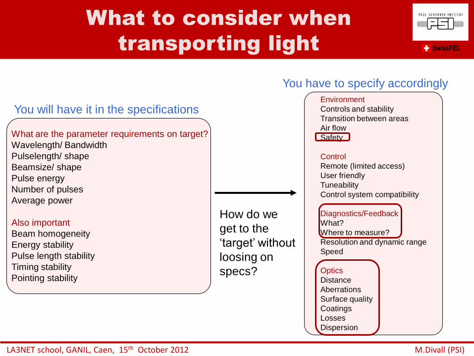
What to consider when
transporting light
LA3NET school, GANIL, Caen, 15th October 2012 M.Divall (PSI)
Environment
Controls and stability
Transition between areas
Air flow
Safety
Control
Remote (limited access)
User friendly
Tuneability
Control system compatibility
Diagnostics/Feedback
What?
Where to measure?
Resolution and dynamic range
Speed
Optics
Distance
Aberrations
Surface quality
Coatings
Losses
Dispersion
What are the parameter requirements on target?
Wavelength/ Bandwidth
Pulselength/ shape
Beamsize/ shape
Pulse energy
Number of pulses
Average power
Also important
Beam homogeneity
Energy stability
Pulse length stability
Timing stability
Pointing stability
You will have it in the specifications
You have to specify accordingly
How do we
get to the
‘target’ without
loosing on
specs?
SwissFEL
• Introduction to laser applications in accelerators
• Laser beam transport – basic optics/ rays/ transfer matrix
– Image relay
– Gaussian beam
– Ray-tracing software
– Waves vs. rays, physical optics
• Why is shaping important? – Gaussian vs. real beams
– Emittance optimization
• Transverse shaping – Spatial filters
– Refractive beam-shapers optics
– Adaptive optics
– Hard aperture
• Longitudinal shaping – Time domain methods
– Frequency domain methods
• Safety
Outline
LA3NET school, GANIL, Caen, 15th October 2012 M.Divall (PSI)
SwissFEL
Recipe
LA3NET school, GANIL, Caen, 15th October 2012 M.Divall (PSI)
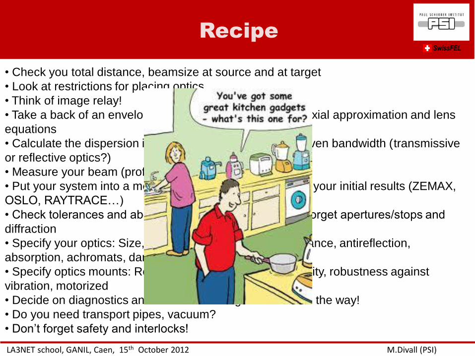
• Check you total distance, beamsize at source and at target
• Look at restrictions for placing optics
• Think of image relay!
• Take a back of an envelope calculation using simple paraxial approximation and lens
equations
• Calculate the dispersion induced by the optics for your given bandwidth (transmissive
or reflective optics?)
• Measure your beam (profile and M-square)
• Put your system into a more advanced code starting with your initial results (ZEMAX,
OSLO, RAYTRACE…)
• Check tolerances and aberrations with real optics, don’t forget apertures/stops and
diffraction
• Specify your optics: Size, surface quality, spectral reflectance, antireflection,
absorption, achromats, damage threshold
• Specify optics mounts: Resolution, precision, reproducibility, robustness against
vibration, motorized
• Decide on diagnostics and feedbacks and get controls on the way!
• Do you need transport pipes, vacuum?
• Don’t forget safety and interlocks!
SwissFEL
Chopper
f=1750mm
laser f=610mm
2 w
f=762mm
f=793mm
1102mm
1846.06mm
1802mm 29
0.9
4m
m
Shutt
er
Pockels
cell
Analy
ser Diagnostics
Dia
gn
ostics
Chopper
f=1750mm
laser f=610mm
2 w
f=762mm
f=793mm
1102mm
1846.06mm
1802mm 29
0.9
4m
m
Shutt
er
l /2 plate
Pockels
cell
Analy
ser Diagnostics
Dia
gn
ostics
Pola
riser
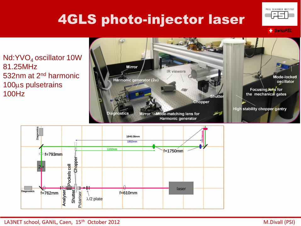
4GLS photo-injector laser SwissFEL
LA3NET school, GANIL, Caen, 15th October 2012 M.Divall (PSI)
Nd:YVO4 oscillator 10W
81.25MHz
532nm at 2nd harmonic
100s pulsetrains
100Hz
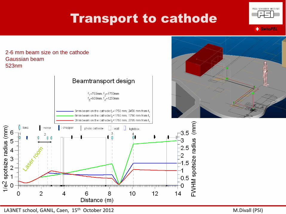
Transport to cathode
LA3NET school, GANIL, Caen, 15th October 2012 M.Divall (PSI)
SwissFEL La
ser ro
om
2-6 mm beam size on the cathode
Gaussian beam
523nm
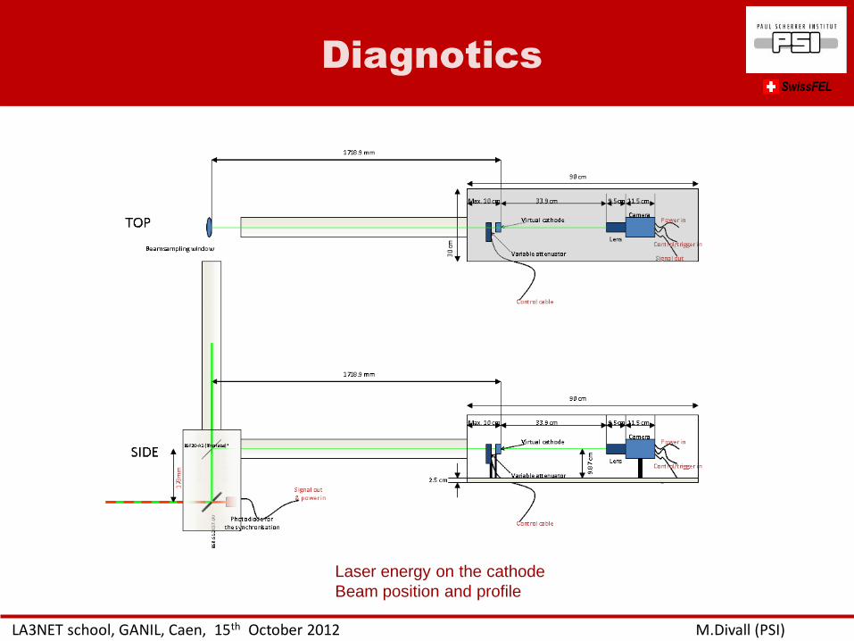
Diagnotics SwissFEL
LA3NET school, GANIL, Caen, 15th October 2012 M.Divall (PSI)
Laser energy on the cathode
Beam position and profile
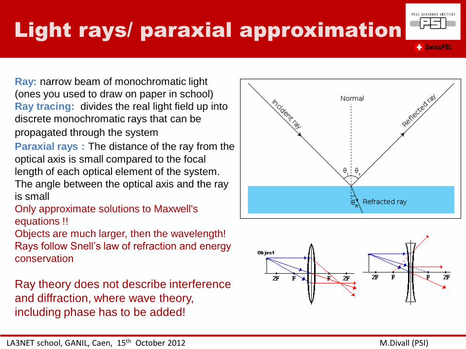
Ray: narrow beam of monochromatic light
(ones you used to draw on paper in school)
Ray tracing: divides the real light field up into
discrete monochromatic rays that can be
propagated through the system
Paraxial rays : The distance of the ray from the
optical axis is small compared to the focal
length of each optical element of the system.
The angle between the optical axis and the ray
is small
Only approximate solutions to Maxwell's
equations !!
Objects are much larger, then the wavelength!
Rays follow Snell’s law of refraction and energy
conservation
Ray theory does not describe interference
and diffraction, where wave theory,
including phase has to be added!
Light rays/ paraxial approximation SwissFEL
LA3NET school, GANIL, Caen, 15th October 2012 M.Divall (PSI)
LA3NET school, GANIL, Caen, 15th October 2012 M.Divall (PSI)
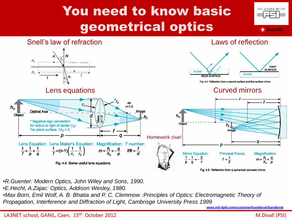
You need to know basic
geometrical optics
•R.Guenter: Modern Optics, John Wiley and Sons, 1990.
•E.Hecht, A.Zajac: Optics, Addison Wesley, 1980.
•Max Born, Emil Wolf, A. B. Bhatia and P. C. Clemmow :Principles of Optics: Electromagnetic Theory of
Propagation, Interference and Diffraction of Light, Cambrisge University Press 1999
Lens equations
Laws of reflection
www.intl-light.com/customer/handbook/handbook
SwissFEL
Snell’s law of refraction
Homework clue!
Curved mirrors
LA3NET school, GANIL, Caen, 15th October 2012 M.Divall (PSI)
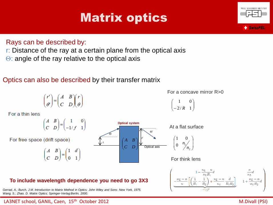
Matrix optics SwissFEL
Optics can also be described by their transfer matrix
Gerrad, A.; Burch, J.M. Introduction to Matrix Method in Optics; John Wiley and Sons: New York, 1975.
Wang, S.; Zhao, D. Matrix Optics; Springer-Verlag:Berlin, 2000.
For a concave mirror R>0
At a flat surface
2
10
01
nn
1/2
01
R
Rays can be described by:
r: Distance of the ray at a certain plane from the optical axis
: angle of the ray relative to the optical axis
DC
BA
Optical system
Optical axis
’
r
r’
For think lens
To include wavelength dependence you need to go 3X3
LA3NET school, GANIL, Caen, 15th October 2012 M.Divall (PSI)
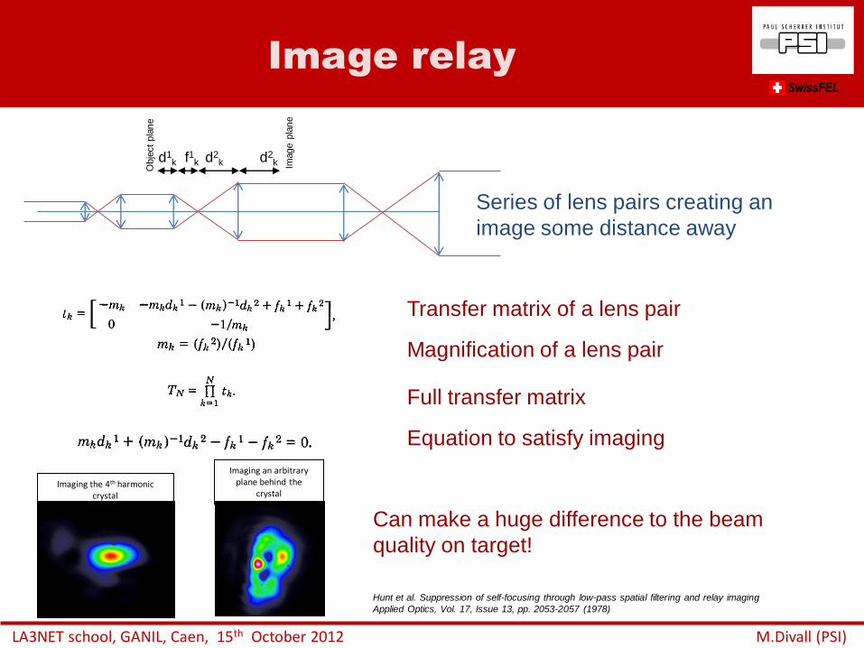
Image relay SwissFEL
Hunt et al. Suppression of self-focusing through low-pass spatial filtering and relay imaging
Applied Optics, Vol. 17, Issue 13, pp. 2053-2057 (1978)
Series of lens pairs creating an
image some distance away
Transfer matrix of a lens pair
Magnification of a lens pair
Full transfer matrix
Equation to satisfy imaging
Imaging the 4th harmonic crystal
Imaging an arbitrary plane behind the
crystal
Can make a huge difference to the beam
quality on target!
d1k f1k d2
k d2k
Obje
ct
pla
ne
Image p
lan
e
LA3NET school, GANIL, Caen, 15th October 2012 M.Divall (PSI)
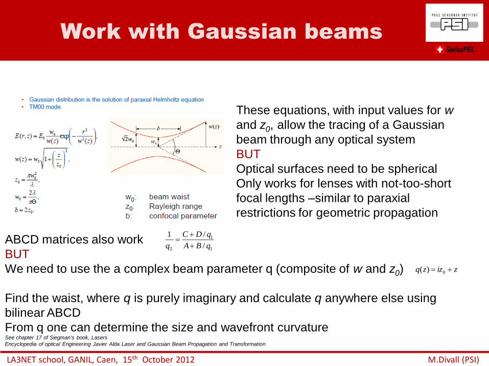
Work with Gaussian beams SwissFEL
These equations, with input values for w
and z0, allow the tracing of a Gaussian
beam through any optical system
BUT
Optical surfaces need to be spherical
Only works for lenses with not-too-short
focal lengths –similar to paraxial
restrictions for geometric propagation
ABCD matrices also work
BUT
We need to use the a complex beam parameter q (composite of w and z0)
Find the waist, where q is purely imaginary and calculate q anywhere else using
bilinear ABCD
From q one can determine the size and wavefront curvature See chapter 17 of Siegman's book, Lasers
Encyclopedia of optical Engineering Javier Alda Laser and Gaussian Beam Propagation and Transformation
zizzq 0)(
1
1
2 /
/1
qBA
qDC
q
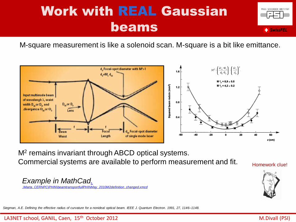
M2 remains invariant through ABCD optical systems.
Commercial systems are available to perform measurement and fit.
Work with REAL Gaussian
beams SwissFEL
M-square measurement is like a solenoid scan. M-square is a bit like emittance.
Siegman, A.E. Defining the effective radius of curvature for a nonideal optical beam. IEEE J. Quantum Electron. 1991, 27, 1146–1148.
LA3NET school, GANIL, Caen, 15th October 2012 M.Divall (PSI)
Example in MathCad. .\Marta_CERNPC\PHIN\beamtransportfullPHINMay_2010M2definition_changed.xmcd
Homework clue!
LA3NET school, GANIL, Caen, 15th October 2012 M.Divall (PSI)
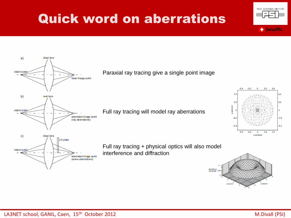
Quick word on aberrations SwissFEL
Paraxial ray tracing give a single point image
Full ray tracing will model ray aberrations
Full ray tracing + physical optics will also model
interference and diffraction
LA3NET school, GANIL, Caen, 15th October 2012 M.Divall (PSI)
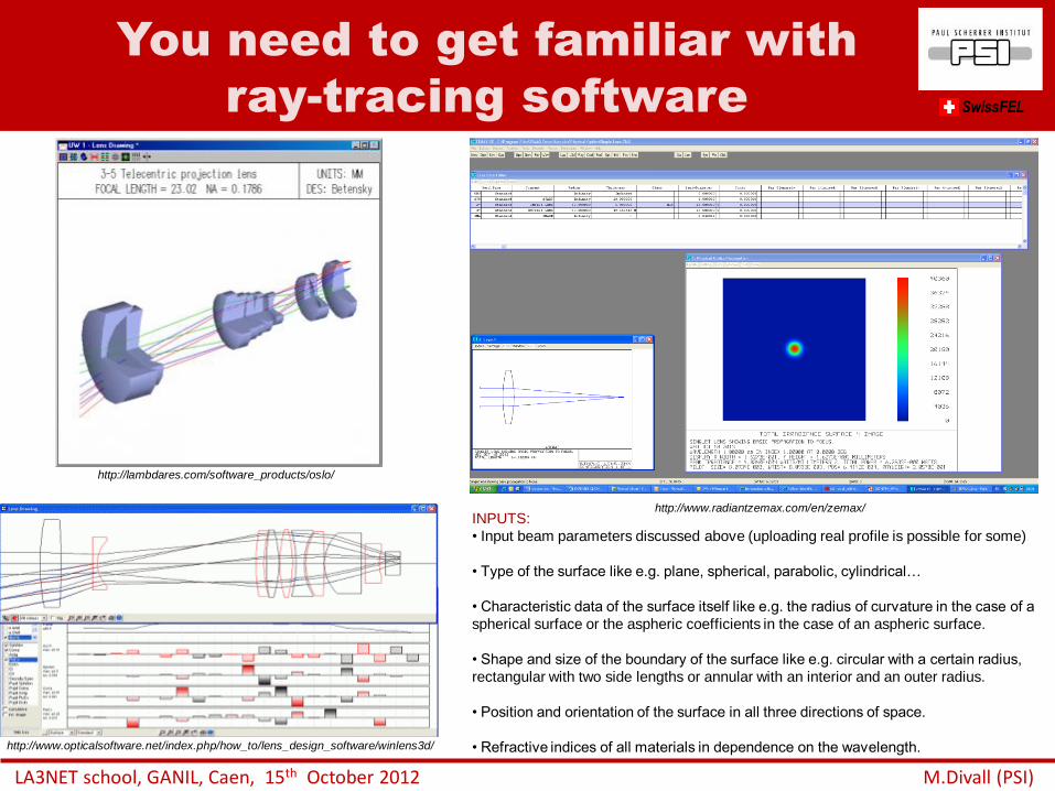
You need to get familiar with
ray-tracing software SwissFEL
http://www.opticalsoftware.net/index.php/how_to/lens_design_software/winlens3d/
http://lambdares.com/software_products/oslo/
http://www.radiantzemax.com/en/zemax/ INPUTS:
• Input beam parameters discussed above (uploading real profile is possible for some)
• Type of the surface like e.g. plane, spherical, parabolic, cylindrical…
• Characteristic data of the surface itself like e.g. the radius of curvature in the case of a
spherical surface or the aspheric coefficients in the case of an aspheric surface.
• Shape and size of the boundary of the surface like e.g. circular with a certain radius,
rectangular with two side lengths or annular with an interior and an outer radius.
• Position and orientation of the surface in all three directions of space.
• Refractive indices of all materials in dependence on the wavelength.
LA3NET school, GANIL, Caen, 15th October 2012 M.Divall (PSI)
Don’t forget to include physical
optics SwissFEL
Fourier optics will decompose complicated linear systems into single
elements and apply a weighing factor.
Enables:
Describing image formation
Full modeling the aberrations of an optical system (also wave aberrations)
Studying the performance of a lens
It allows to calculate diffraction and interference, which simple ray-tracing
does not do
Modeling diffraction patterns and light propagation
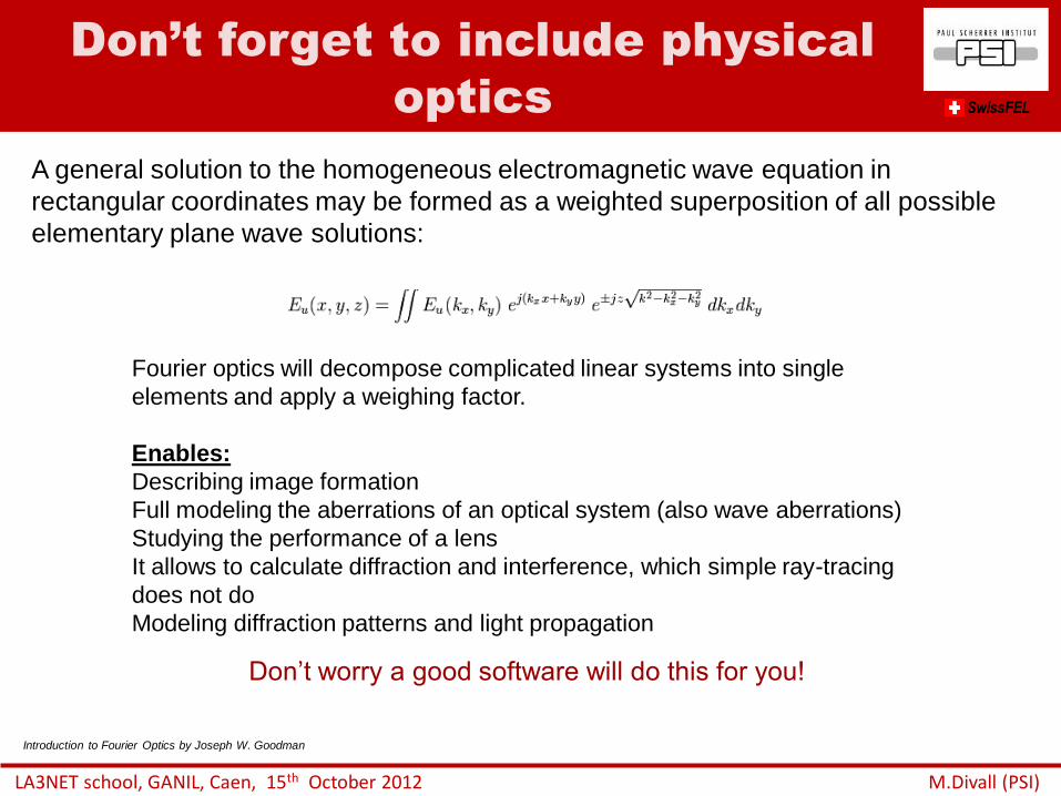
A general solution to the homogeneous electromagnetic wave equation in
rectangular coordinates may be formed as a weighted superposition of all possible
elementary plane wave solutions:
Introduction to Fourier Optics by Joseph W. Goodman
Don’t worry a good software will do this for you!
Checklist
LA3NET school, GANIL, Caen, 15th October 2012 M.Divall (PSI)
• Check you total distance, beamsize at source and at target
• Look at restrictions for placing optics
• Think of image relay!
• Take a back of an envelope calculation using simple paraxial approximation and lens
equations
• Calculate the dispersion induced by the optics for your given bandwidth (transmissive
or reflective optics?) LATER!!
• Measure your beam (profile and M-square)
• Put your system into a more advanced code starting with your initial results (ZEMAX,
OSLO, RAYTRACE…)
• Check tolerances and aberrations with real optics, don’t forget apertures/stops and
diffraction
• Specify your optics: Size, surface quality, spectral reflectance, antireflection,
absorption, achromats, damage threshold
• Specify optics mounts: Resolution, precision, reproducibility, robustness against
vibration, motorized
• Decide on diagnostics and feedbacks and get controls on the way!
• Do you need transport pipes, vacuum?
• Don’t forget safety and interlocks!
SwissFEL
• Introduction to laser applications in accelerators
• Laser beam transport – basic optics/ rays/ transfer matrix
– Image relay
– Gaussian beam
– Ray-tracing softwares
– Waves vs. rays, physical optics
• Why is shaping important? – Gaussian vs. real beams
– Emittance optimization
• Transverse shaping – Spatial filters
– Refractive beam-shapers optics
– Adaptive optics
– Hard aperture
• Longitudinal shaping – Time domain methods
– Frequency domain methods
• Safety
Outline
LA3NET school, GANIL, Caen, 15th October 2012 M.Divall (PSI)
SwissFEL
LA3NET school, GANIL, Caen, 15th October 2012 M.Divall (PSI)
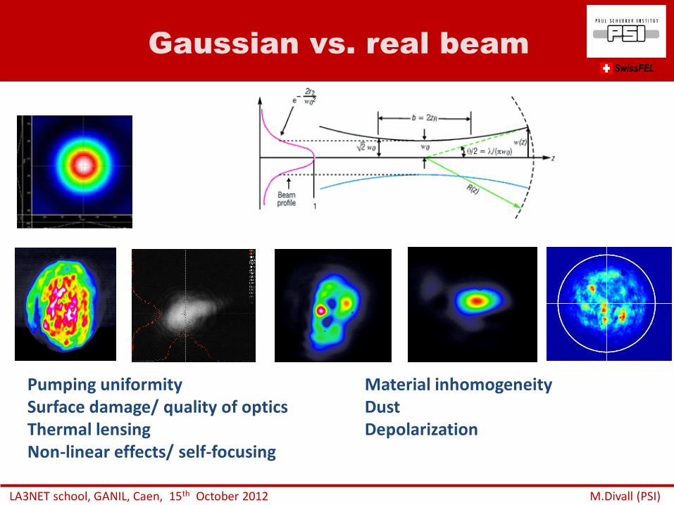
Gaussian vs. real beam
Pumping uniformity Material inhomogeneity Surface damage/ quality of optics Dust Thermal lensing Depolarization Non-linear effects/ self-focusing
SwissFEL
LA3NET school, GANIL, Caen, 15th October 2012 M.Divall (PSI)
A little bit on nonlinear effects SwissFEL
Hunt et al. Suppression of self-focusing through low-pass spatial filtering and relay imaging
Applied Optics, Vol. 17, Issue 13, pp. 2053-2057 (1978)
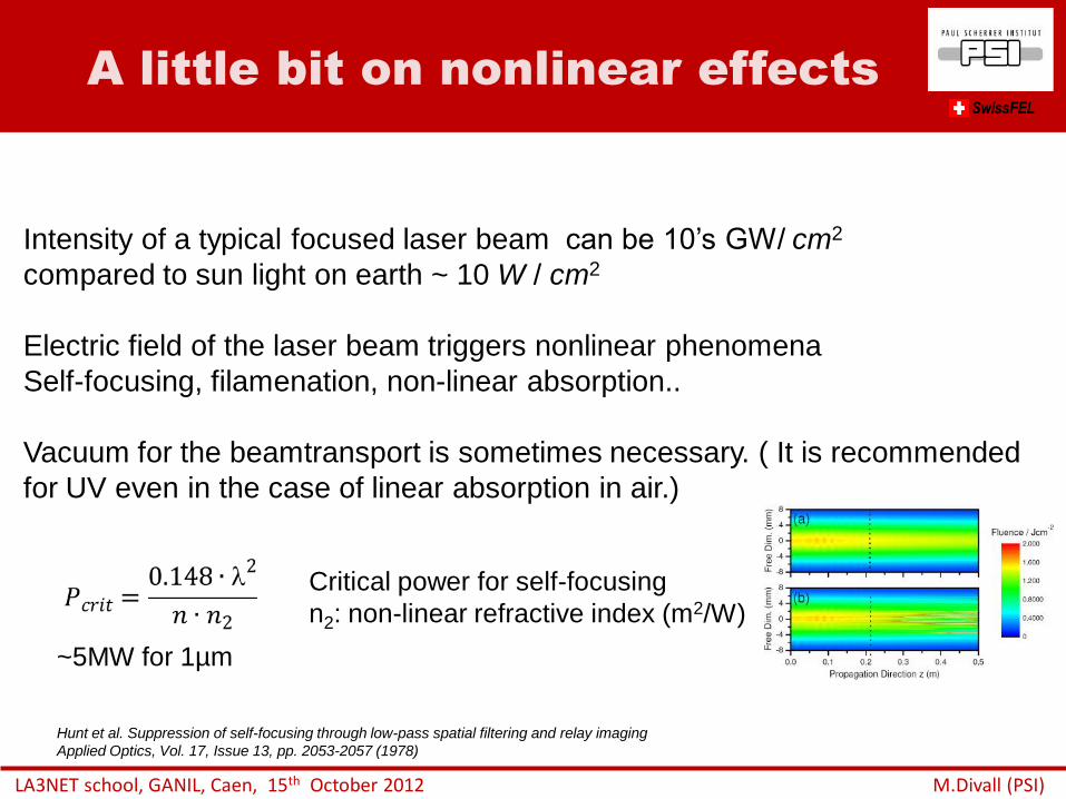
Intensity of a typical focused laser beam can be 10’s GW/ cm2
compared to sun light on earth ~ 10 W / cm2
Electric field of the laser beam triggers nonlinear phenomena
Self-focusing, filamenation, non-linear absorption..
Vacuum for the beamtransport is sometimes necessary. ( It is recommended
for UV even in the case of linear absorption in air.)
Critical power for self-focusing
n2: non-linear refractive index (m2/W)
~5MW for 1µm
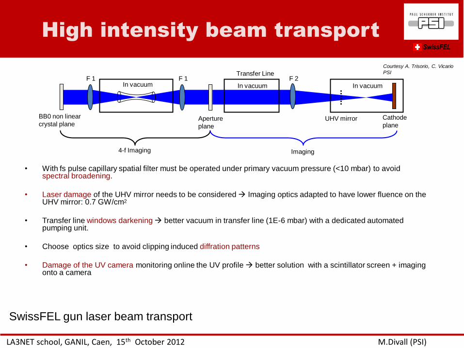
High intensity beam transport
LA3NET school, GANIL, Caen, 15th October 2012 M.Divall (PSI)
• With fs pulse capillary spatial filter must be operated under primary vacuum pressure (<10 mbar) to avoid spectral broadening.
• Laser damage of the UHV mirror needs to be considered Imaging optics adapted to have lower fluence on the UHV mirror: 0.7 GW/cm2
• Transfer line windows darkening better vacuum in transfer line (1E-6 mbar) with a dedicated automated pumping unit.
• Choose optics size to avoid clipping induced diffration patterns
• Damage of the UV camera monitoring online the UV profile better solution with a scintillator screen + imaging onto a camera
BB0 non linear
crystal plane
In vacuum
Cathode
plane Aperture
plane
In vacuum
UHV mirror
In vacuum F 1 F 1 F 2
4-f Imaging Imaging
Transfer Line
SwissFEL
Courtesy A. Trisorio, C. Vicario
PSI
SwissFEL gun laser beam transport
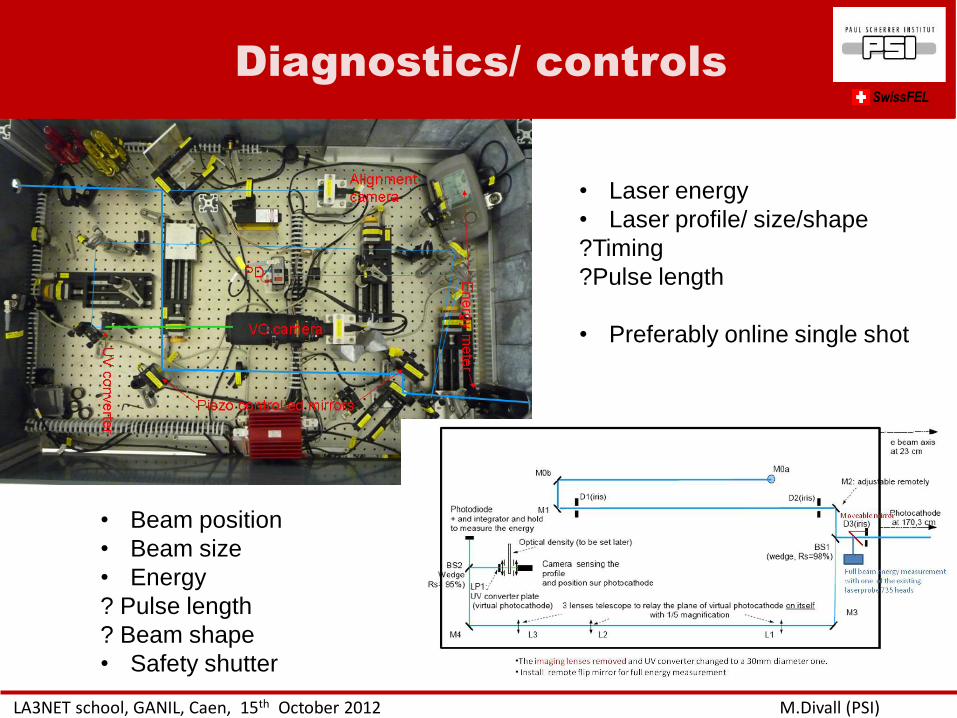
Diagnostics/ controls SwissFEL
LA3NET school, GANIL, Caen, 15th October 2012 M.Divall (PSI)
• Laser energy
• Laser profile/ size/shape
?Timing
?Pulse length
• Preferably online single shot
• Beam position
• Beam size
• Energy
? Pulse length
? Beam shape
• Safety shutter
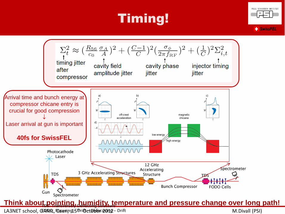
Timing!
LA3NET school, GANIL, Caen, 15th October 2012 M.Divall (PSI)
SwissFEL
Arrival time and bunch energy at
compressor chicane entry is
crucial for good compression
Laser arrival at gun is important
40fs for SwissFEL
Think about pointing, humidity, temperature and pressure change over long path!

• Introduction to laser applications in accelerators
• Laser beam transport – basic optics/ rays/ transfer matrix
– Image relay
– Gaussian beam
– Ray-tracing softwares
– Waves vs. rays, physical optics
• Why is shaping important? – Gaussian vs. real beams
– Emittance optimization
• Transverse shaping – Spatial filters
– Refractive beam-shapers optics
– Adaptive optics
– Hard aperture
• Longitudinal shaping – Time domain methods
– Frequency domain methods
• Safety
Outline
LA3NET school, GANIL, Caen, 15th October 2012 M.Divall (PSI)
SwissFEL
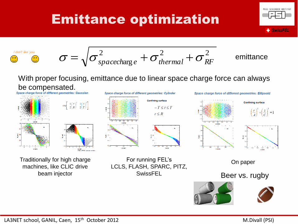
Emittance optimization SwissFEL
LA3NET school, GANIL, Caen, 15th October 2012 M.Divall (PSI)
222
arg RFthermalespacech
Traditionally for high charge
machines, like CLIC drive
beam injector
For running FEL’s
LCLS, FLASH, SPARC, PITZ,
SwissFEL
On paper
With proper focusing, emittance due to linear space charge force can always
be compensated.
I don’t like you
Beer vs. rugby
emittance
• Introduction to laser applications in accelerators
• Laser beam transport – basic optics/ rays/ transfer matrix
– Image relay
– Gaussian beam
– Ray-tracing softwares
– Waves vs. rays, physical optics
• Why is shaping important? – Gaussian vs. real beams
– Emittance optimization
• Transverse shaping – Spatial filters
– Refractive beam-shapers optics
– Adaptive optics
– Hard aperture
• Longitudinal shaping – Time domain methods
– Frequency domain methods
• Safety
Outline
LA3NET school, GANIL, Caen, 15th October 2012 M.Divall (PSI)
SwissFEL
• The focus of the lens (far field) give the Fourier-transform of
the object mask (near-field pattern)
• Light in the very center of the transform pattern corresponds
to a perfect plane wave
• Light further from the central spot corresponding to structure
with higher spatial frequency
Rule of thumb:
Pinhole diameter=8Wavelength Focal length/( Beam diameter before lens)
This is to clean up your beam
http://www.newport.com/Spatial-Filters/144910/1033/content.aspx
LA3NET school, GANIL, Caen, 15th October 2012 M.Divall (PSI)
Spatial filters SwissFEL
Spatial frequency
Focus
Pinhole
‘Soft’ aperture
Main techniques for shaping
LA3NET school, GANIL, Caen, 15th October 2012 M.Divall (PSI)
SwissFEL
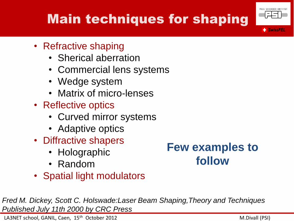
• Refractive shaping
• Sherical aberration
• Commercial lens systems
• Wedge system
• Matrix of micro-lenses
• Reflective optics
• Curved mirror systems
• Adaptive optics
• Diffractive shapers
• Holographic
• Random
• Spatial light modulators
Fred M. Dickey, Scott C. Holswade:Laser Beam Shaping,Theory and Techniques
Published July 11th 2000 by CRC Press
Few examples to
follow
Refractive shaping
LA3NET school, GANIL, Caen, 15th October 2012 M.Divall (PSI)
SwissFEL
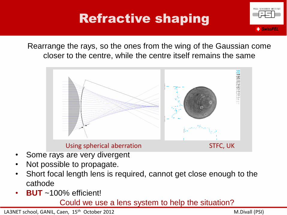
Using spherical aberration STFC, UK
Rearrange the rays, so the ones from the wing of the Gaussian come
closer to the centre, while the centre itself remains the same
• Some rays are very divergent
• Not possible to propagate.
• Short focal length lens is required, cannot get close enough to the
cathode
• BUT ~100% efficient!
Could we use a lens system to help the situation?
LA3NET school, GANIL, Caen, 15th October 2012 M.Divall (PSI)
SwissFEL
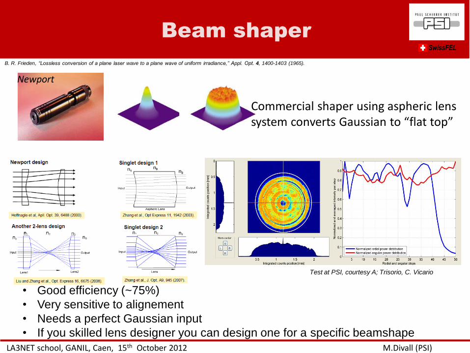
Commercial shaper using aspheric lens system converts Gaussian to “flat top”
Newport
B. R. Frieden, “Lossless conversion of a plane laser wave to a plane wave of uniform irradiance,” Appl. Opt. 4, 1400-1403 (1965).
Test at PSI, courtesy A; Trisorio, C. Vicario
• Good efficiency (~75%)
• Very sensitive to alignement
• Needs a perfect Gaussian input
• If you skilled lens designer you can design one for a specific beamshape
Beam shaper
Microlens
LA3NET school, GANIL, Caen, 15th October 2012 M.Divall (PSI)
SwissFEL
• Relies on the partial coherence
properties of the source
• The periodic nature of the array
limits its beam shaping capabilities
• Fabrication errors that lead to lens-
to-lens variations result in non-
uniformity in the scatter intensity
profile.
• High transmission (> 90 %)
• Poor beam quality:
- Rms angular=0.82
- Rms radial=0.69
• BUT Alignment insensitive
Test at PSI, courtesy A; Trisorio, C. Vicario
Proceedings of SPIE Vol. 5175 Laser Beam Shaping IV, edited by Fred M. Dickey,
David L. Shealy (SPIE, Bellingham, WA, 2003)
• Need to completely cover the plane of the array with
the desired boundary type!
• Need for structured arrays
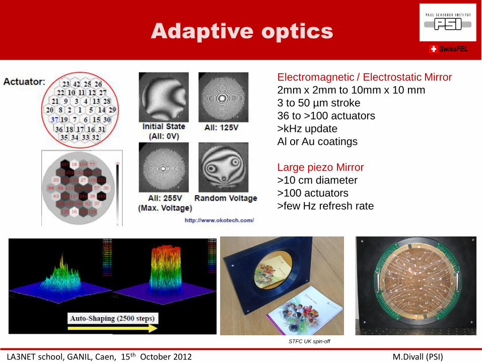
Adaptive optics
LA3NET school, GANIL, Caen, 15th October 2012 M.Divall (PSI)
SwissFEL
Electromagnetic / Electrostatic Mirror
2mm x 2mm to 10mm x 10 mm
3 to 50 µm stroke
36 to >100 actuators
>kHz update
Al or Au coatings
Large piezo Mirror
>10 cm diameter
>100 actuators
>few Hz refresh rate
STFC UK spin-off
Diffractive shaping
LA3NET school, GANIL, Caen, 15th October 2012 M.Divall (PSI)
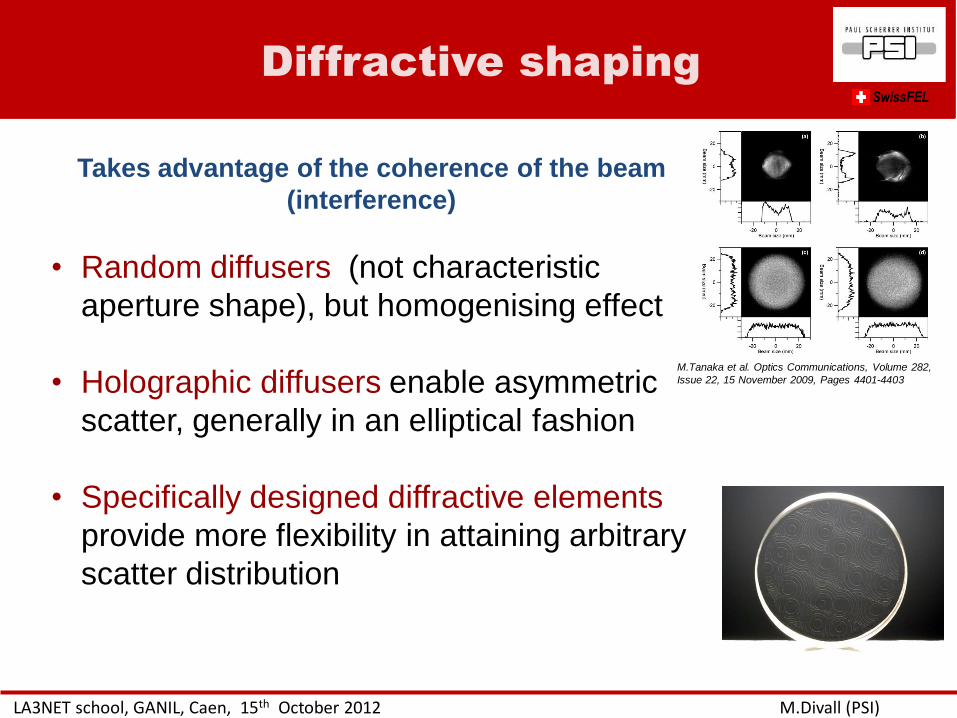
SwissFEL
Takes advantage of the coherence of the beam
(interference)
• Random diffusers (not characteristic
aperture shape), but homogenising effect
• Holographic diffusers enable asymmetric
scatter, generally in an elliptical fashion
• Specifically designed diffractive elements
provide more flexibility in attaining arbitrary
scatter distribution
M.Tanaka et al. Optics Communications, Volume 282,
Issue 22, 15 November 2009, Pages 4401-4403
Diffractive shaping
LA3NET school, GANIL, Caen, 15th October 2012 M.Divall (PSI)
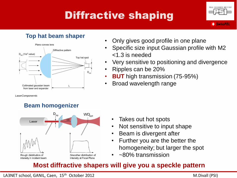
SwissFEL
• Only gives good profile in one plane
• Specific size input Gaussian profile with M2
<1.3 is needed
• Very sensitive to positioning and divergence
• Ripples can be 20%
• BUT high transmission (75-95%)
• Broad wavelength range
Top hat beam shaper
Beam homogenizer
• Takes out hot spots
• Not sensitive to input shape
• Beam is divergent after
• Further you are the better the
homogeneity; but larger the spot
• ~80% transmission
Most diffractive shapers will give you a speckle pattern
LaserComponernts
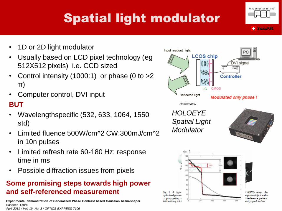
• 1D or 2D light modulator
• Usually based on LCD pixel technology (eg
512X512 pixels) i.e. CCD sized
• Control intensity (1000:1) or phase (0 to >2
π)
• Computer control, DVI input
BUT
• Wavelengthspecific (532, 633, 1064, 1550
std)
• Limited fluence 500W/cm^2 CW:300mJ/cm^2
in 10n pulses
• Limited refresh rate 60-180 Hz; response
time in ms
• Possible diffraction issues from pixels
Hamamatsu
HOLOEYE
Spatial Light
Modulator
Spatial light modulator SwissFEL
Experimental demonstration of Generalized Phase Contrast based Gaussian beam-shaper
Sandeep Tauro
April 2011 / Vol. 19, No. 8 / OPTICS EXPRESS 7106
Some promising steps towards high power
and self-referenced measurement
Conclusion
LA3NET school, GANIL, Caen, 15th October 2012 M.Divall (PSI)
SwissFEL
• So far refractive and diffractive solutions not worked for
accelerators (LCLS, SPARC, PITZ, PSI)
• Most needs very accurate fabrication, difficult to make
• Most are either sensitive to alignment or don’t give good
homogeneity
• The beam tends not to propagate well (needs image
relay)
• Dispersion can be a problem for short pulses
• Reflective design possible as an alternative for refractive
optics
Relay imaging and good spatial filtering is
always necessary
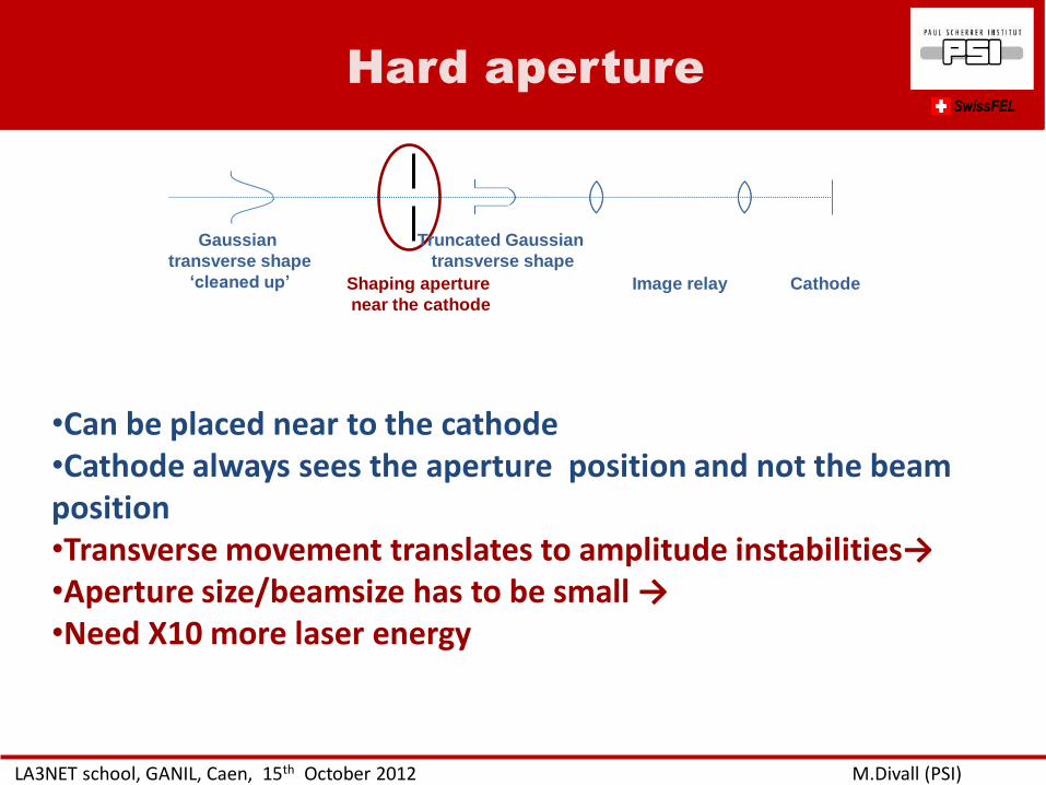
Hard aperture
LA3NET school, GANIL, Caen, 15th October 2012 M.Divall (PSI)
SwissFEL
Gaussian
transverse shape
‘cleaned up’ Shaping aperture
near the cathode
Image relay Cathode
•Can be placed near to the cathode •Cathode always sees the aperture position and not the beam position •Transverse movement translates to amplitude instabilities→ •Aperture size/beamsize has to be small → •Need X10 more laser energy
Truncated Gaussian
transverse shape
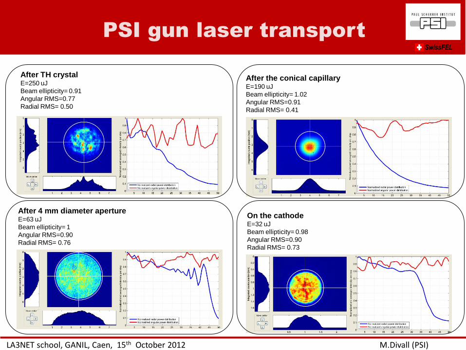
PSI gun laser transport
LA3NET school, GANIL, Caen, 15th October 2012 M.Divall (PSI)
SwissFEL
After TH crystal E=250 uJ
Beam ellipticity= 0.91
Angular RMS=0.77
Radial RMS= 0.50
After the conical capillary E=190 uJ
Beam ellipticity= 1.02
Angular RMS=0.91
Radial RMS= 0.41
After 4 mm diameter aperture E=63 uJ
Beam ellipticity= 1
Angular RMS=0.90
Radial RMS= 0.76
On the cathode E=32 uJ
Beam ellipticity= 0.98
Angular RMS=0.90
Radial RMS= 0.73
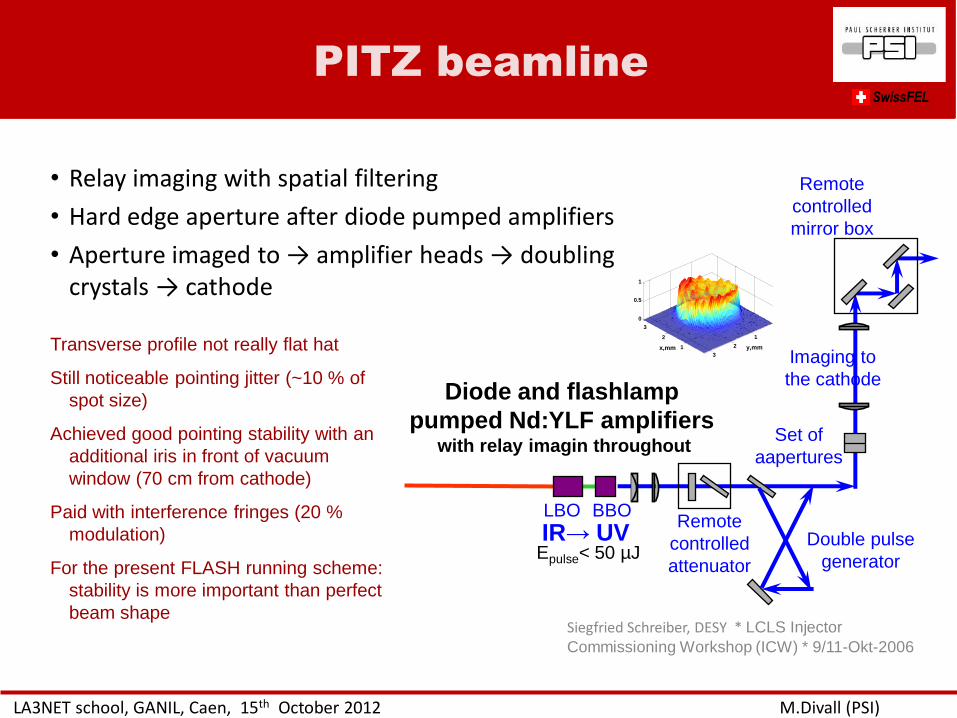
PITZ beamline
LA3NET school, GANIL, Caen, 15th October 2012 M.Divall (PSI)
SwissFEL
• Relay imaging with spatial filtering
• Hard edge aperture after diode pumped amplifiers
• Aperture imaged to → amplifier heads → doubling crystals → cathode
Transverse profile not really flat hat
Still noticeable pointing jitter (~10 % of
spot size)
Achieved good pointing stability with an
additional iris in front of vacuum
window (70 cm from cathode)
Paid with interference fringes (20 %
modulation)
For the present FLASH running scheme:
stability is more important than perfect
beam shape Siegfried Schreiber, DESY * LCLS Injector
Commissioning Workshop (ICW) * 9/11-Okt-2006
Diode and flashlamp
pumped Nd:YLF amplifiers with relay imagin throughout
LBO BBO
IR→ UV Epulse< 50 µJ
Remote
controlled
attenuator
Double pulse
generator
Set of
aapertures
Imaging to
the cathode
Remote
controlled
mirror box
1
2
3
1
2
3
0
0.5
1
y,mmx,mm
• Introduction to laser applications in accelerators
• Laser beam transport – basic optics/ rays/ transfer matrix
– Image relay
– Gaussian beam
– Ray-tracing softwares
– Waves vs. rays, physical optics
• Why is shaping important? – Gaussian vs. real beams
– Emittance optimization
• Transverse shaping – Spatial filters
– Refractive beam-shapers optics
– Adaptive optics
– Hard aperture
• Longitudinal shaping – Laser types
– Time domain methods
– Frequency domain methods
• Safety
Outline
LA3NET school, GANIL, Caen, 15th October 2012 M.Divall (PSI)
SwissFEL
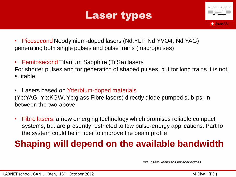
Laser types
LA3NET school, GANIL, Caen, 15th October 2012 M.Divall (PSI)
SwissFEL
• Picosecond Neodymium-doped lasers (Nd:YLF, Nd:YVO4, Nd:YAG)
generating both single pulses and pulse trains (macropulses)
• Femtosecond Titanium Sapphire (Ti:Sa) lasers
For shorter pulses and for generation of shaped pulses, but for long trains it is not
suitable
• Lasers based on Ytterbium-doped materials
(Yb:YAG, Yb:KGW, Yb:glass Fibre lasers) directly diode pumped sub-ps; in
between the two above
• Fibre lasers, a new emerging technology which promises reliable compact
systems, but are presently restricted to low pulse-energy applications. Part fo
the system could be in fiber to improve the beam profile
I.Will : DRIVE LASERS FOR PHOTOINJECTORS
Shaping will depend on the available bandwidth
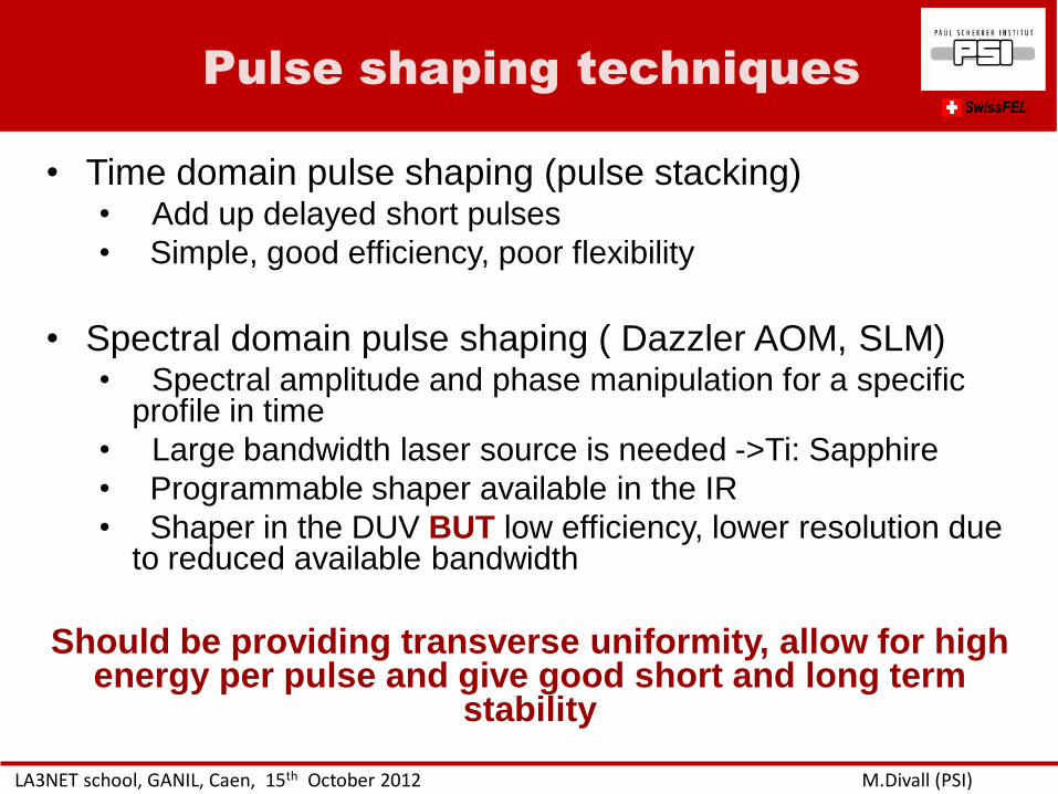
Pulse shaping techniques
LA3NET school, GANIL, Caen, 15th October 2012 M.Divall (PSI)
SwissFEL
• Time domain pulse shaping (pulse stacking) • Add up delayed short pulses
• Simple, good efficiency, poor flexibility
• Spectral domain pulse shaping ( Dazzler AOM, SLM) • Spectral amplitude and phase manipulation for a specific
profile in time
• Large bandwidth laser source is needed ->Ti: Sapphire
• Programmable shaper available in the IR
• Shaper in the DUV BUT low efficiency, lower resolution due to reduced available bandwidth
Should be providing transverse uniformity, allow for high energy per pulse and give good short and long term
stability
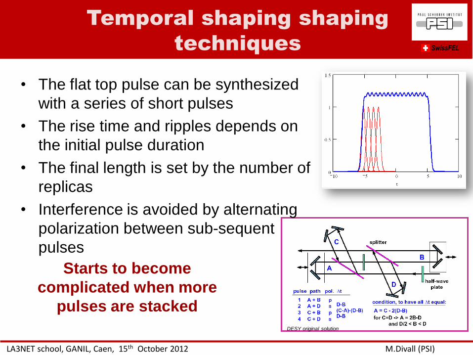
Temporal shaping shaping
techniques
LA3NET school, GANIL, Caen, 15th October 2012 M.Divall (PSI)
SwissFEL
• The flat top pulse can be synthesized
with a series of short pulses
• The rise time and ripples depends on
the initial pulse duration
• The final length is set by the number of
replicas
• Interference is avoided by alternating
polarization between sub-sequent
pulses
DESY original solution
Starts to become
complicated when more
pulses are stacked
Double refraction
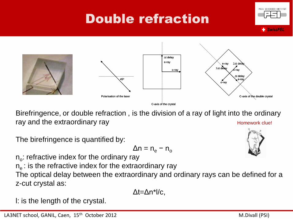
LA3NET school, GANIL, Caen, 15th October 2012 M.Divall (PSI)
SwissFEL
Polarisation of the laser
45o
C-axis of the double crystal
o-ray
e-ray
t delay
C-axis of the crystal
o-ray
e-ray
t delay
o-raye-ray
t delay
t delay
Polarisation of the laser
45o
C-axis of the double crystal
o-ray
e-ray
t delay
C-axis of the crystal
o-ray
e-ray
t delay
o-raye-ray
t delay
t delay
Birefringence, or double refraction , is the division of a ray of light into the ordinary
ray and the extraordinary ray
The birefringence is quantified by:
Δn = ne − no
no: refractive index for the ordinary ray
ne : is the refractive index for the extraordinary ray
The optical delay between the extraordinary and ordinary rays can be defined for a
z-cut crystal as:
Δt=Δn*l/c,
l: is the length of the crystal.
Homework clue!
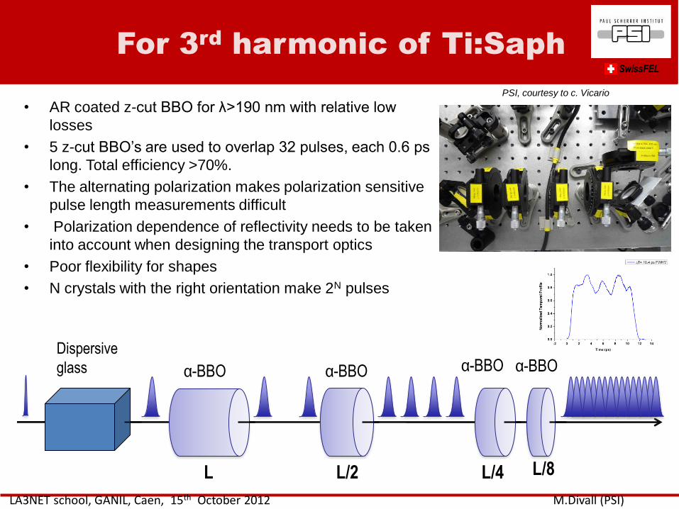
For 3rd
harmonic of Ti:Saph
LA3NET school, GANIL, Caen, 15th October 2012 M.Divall (PSI)
SwissFEL
• AR coated z-cut BBO for λ>190 nm with relative low
losses
• 5 z-cut BBO’s are used to overlap 32 pulses, each 0.6 ps
long. Total efficiency >70%.
• The alternating polarization makes polarization sensitive
pulse length measurements difficult
• Polarization dependence of reflectivity needs to be taken
into account when designing the transport optics
• Poor flexibility for shapes
• N crystals with the right orientation make 2N pulses
L L/2 L/4 L/8
α-BBO α-BBO α-BBO α-BBO Dispersive
glass
PSI, courtesy to c. Vicario
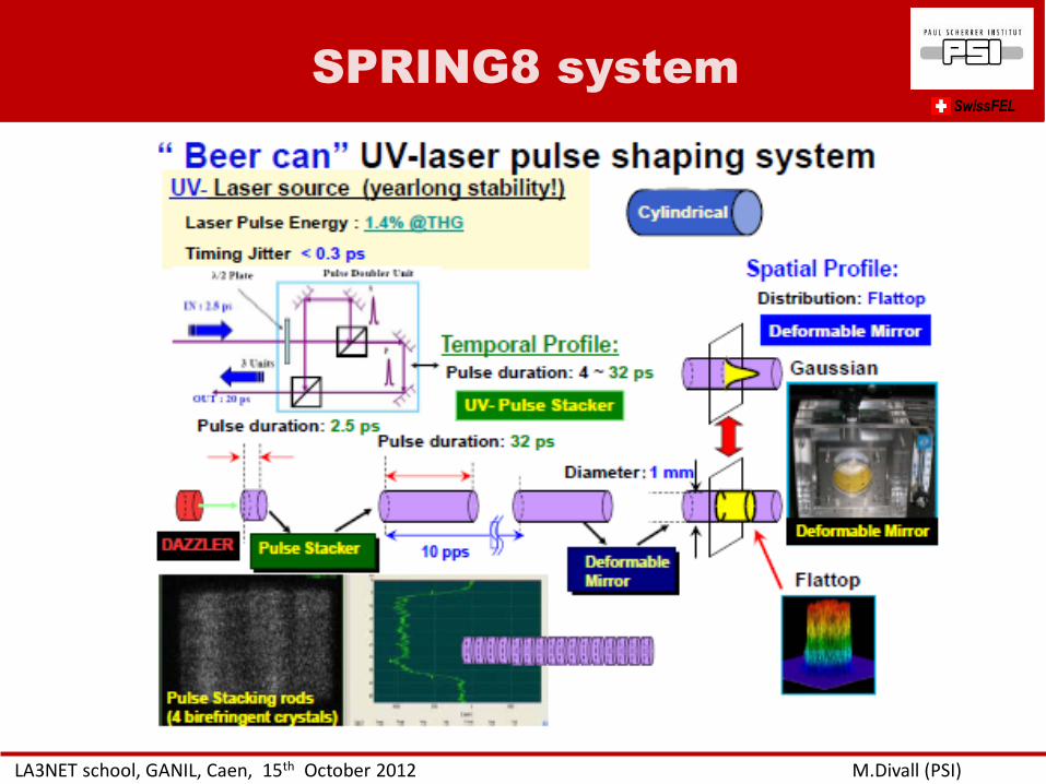
SPRING8 system
LA3NET school, GANIL, Caen, 15th October 2012 M.Divall (PSI)
SwissFEL
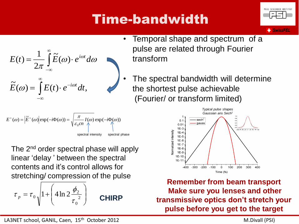
Time-bandwidth
LA3NET school, GANIL, Caen, 15th October 2012 M.Divall (PSI)
SwissFEL
ww
w deEtE ti)(~
2
1)(
,)()(~
dtetEE tiww
• Temporal shape and spectrum of a
pulse are related through Fourier
transform
• The spectral bandwidth will determine
the shortest pulse achievable
(Fourier/ or transform limited)
))(exp()())(exp()(~
)(0
ww
www iI
cniEE
spectral intensity spectral phase
Typical pulse shapes
Gaussian ans Sech2
2
0
20 2ln41
p
The 2nd order spectral phase will apply
linear ‘delay ’ between the spectral
contents and it’s control allows for
stretching/ compression of the pulse Remember from beam transport
Make sure you lenses and other
transmissive optics don’t stretch your
pulse before you get to the target
CHIRP
Time-domain techniques
LA3NET school, GANIL, Caen, 15th October 2012 M.Divall (PSI)
SwissFEL
Professor J Benjamin C Whitaker
input
ne
no
output
Undiffracted
output
• Stretching with grating or prism based
stretcher.
• Applying modulation to the spectrum • Acousto-optic modulator (e.g. DAZZLER)
• Spatial light modulator in Fourier plane
• Compress (transform back) and get
the specific pulse shape for the
corresponding programmed spectrum
Can also compensate for dispersion in the system
DAZZLER
LA3NET school, GANIL, Caen, 15th October 2012 M.Divall (PSI)
SwissFEL
input
ne
no
output
Undiffracted
output •Dazzler is a commercial Acousto Optic
Filter.
•Programmable acoustic wave interacts
with the optical wave in a birefringent
crystal
•Available for specific wavelengths
•The optical wavelengths are selectively
•retarded (spectral phase shaping)
•diffracted (spectral amplitude
shaping)
PSI application directly in UV
• Versatile
BUT
• Limited damage threshold and absorption
losses (max output ~25uJ in few ps’s)
• Need to pre-stretch for longer pulses (>4ps)
A. Trisorio et al. Appl. Phys B, 105, 255 (2011).
C. Vicario, “Laser temporal pulse shaping experiment
for SPARC photoinjector”, EPAC’04, Lucerne, July
2004, p. 1300, http://www.jacow.org.
Chirp mathcing
LA3NET school, GANIL, Caen, 15th October 2012 M.Divall (PSI)
SwissFEL
Refractive index depends on Temperature
Angle of the beam
Wavelength
Polarization
Conversion efficiency depends on Temperature
Angle and divergence of the beam
Wavelength and spectral bandwidth
Intensity
Crystal length
Polarization
e-wave
o-wave
Θ
ρ
For broadband pulses the spectrum is distroted and limited after conversion.
0
kS
ΔΦ
kS
k2
k1
k2-
k1-
k2+
k1+ phase matching
Transform limited pulses
Mixing oppositely chirped pulses from two
compressors Single short pulse
Chirp-matched pulses
k3
k1
0
kS
ΔΦ
kS
k2 k2- k2+
k1+ k1-
k3 k3+
k3-
1K. Osvay, I.N. Ross, J. Opt. Soc. Am. B Vol. 13, No. 7 p 1431 (1996)
o The output pulse is linearly chirped, and there is a direct correspondence
between spectral and temporal shape
o The compressors are set to satisfy the chirp matched condition
o The chirp matching SFG permit to efficiently transfer the spectral shape in the
DUV without distortions
o The IR shaper can be used to have top hat IR spectrum in both compressors
o The use of chirp matched SFG can be applied to the generation of flat top
pulse
Chirp matching at PSI SwissFEL
LA3NET school, GANIL, Caen, 15th October 2012 M.Divall (PSI)
C. Vicarion et al. Optics Letters
Conclusions
o Pulse stacking is most robust for high charge operation
o For fast rise times broadband source Yb based or Ti:Saph is needed
o Efficient and simple approach to generate the flat top pulse
o Measurements indicate a reduction of beam emittance respect to the Gaussian shape
o UV dazzler
o The technique can be used for the low charge emittance optimization
o The use of chirp-matched SFG allows efficient generation of broadband pulses potentially applicable to RF gun, but need to improve the amplitude stability
October 16, 2012 PSI 56
Conclusions SwissFEL
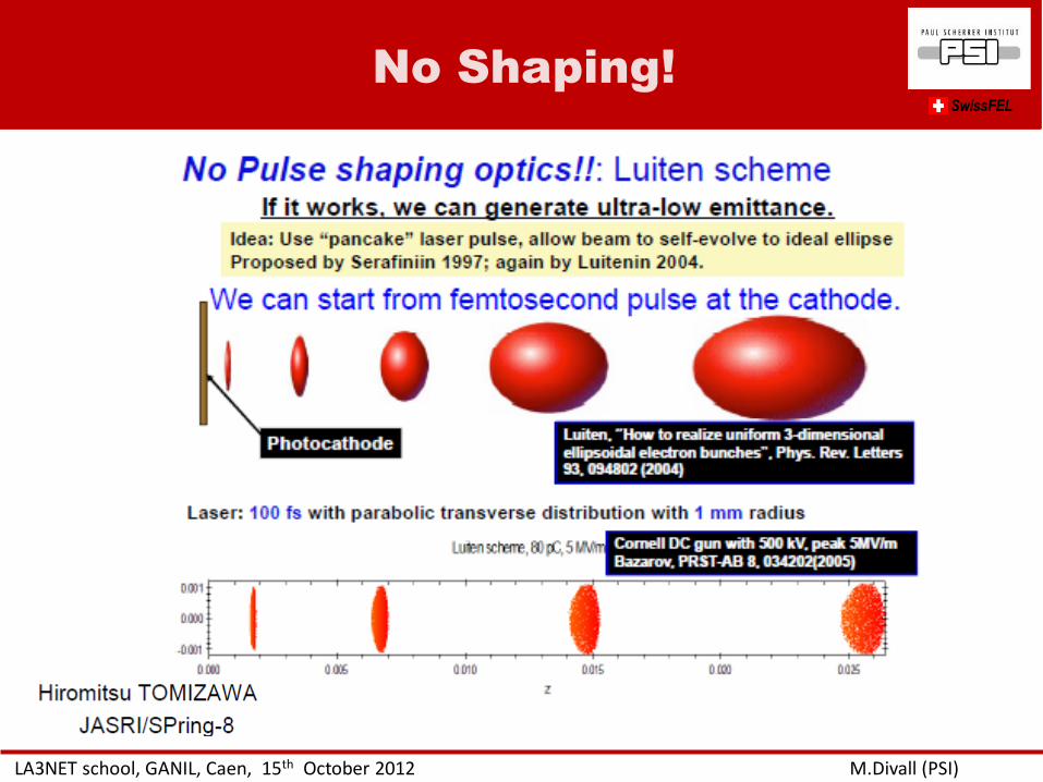
No Shaping!
LA3NET school, GANIL, Caen, 15th October 2012 M.Divall (PSI)
SwissFEL
• Introduction to laser applications in accelerators
• Laser beam transport – basic optics/ rays/ transfer matrix
– Image relay
– Gaussian beam
– Ray-tracing softwares
– Waves vs. rays, physical optics
• Why is shaping important? – Gaussian vs. real beams
– Emittance optimization
• Transverse shaping – Spatial filters
– Refractive beam-shapers optics
– Adaptive optics
– Hard aperture
• Longitudinal shaping – Time domain methods
– Frequency domain methods
• Safety
Outline
LA3NET school, GANIL, Caen, 15th October 2012 M.Divall (PSI)
SwissFEL
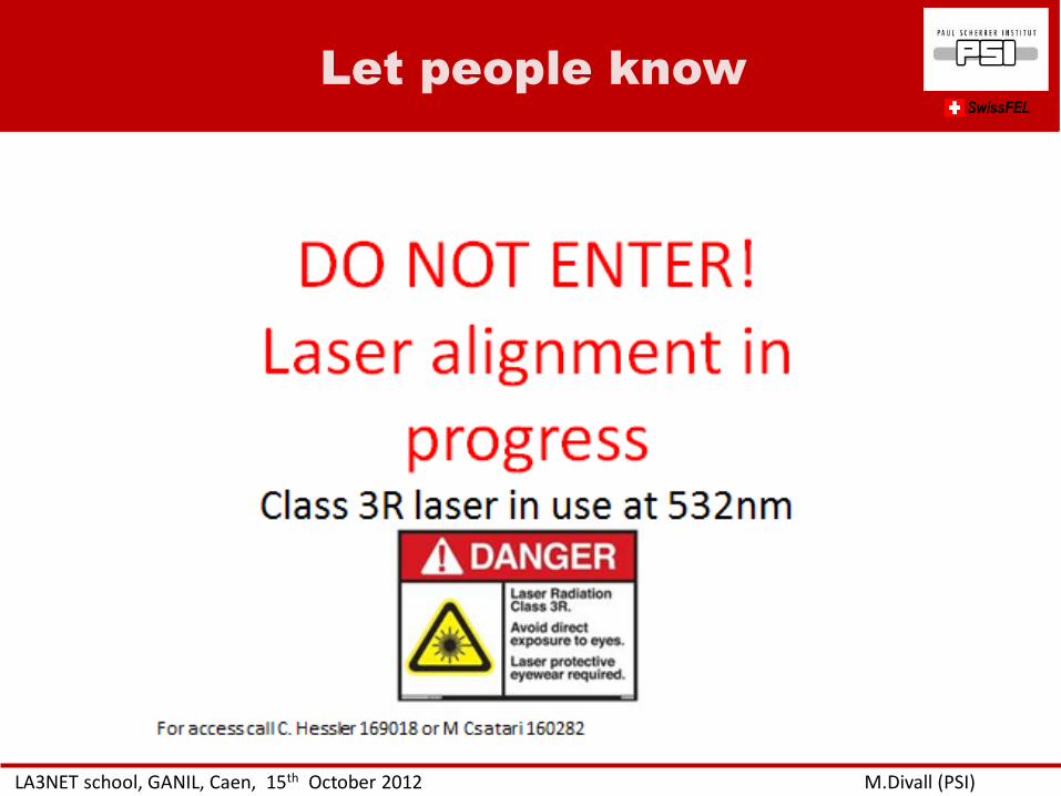
Let people know
LA3NET school, GANIL, Caen, 15th October 2012 M.Divall (PSI)
SwissFEL
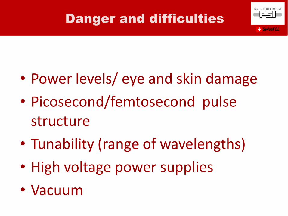
• Power levels/ eye and skin damage
• Picosecond/femtosecond pulse structure
• Tunability (range of wavelengths)
• High voltage power supplies
• Vacuum
Danger and difficulties SwissFEL
Procedures
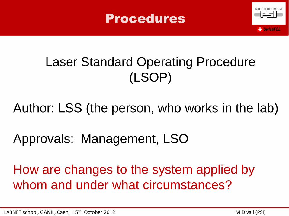
LA3NET school, GANIL, Caen, 15th October 2012 M.Divall (PSI)
SwissFEL
Laser Standard Operating Procedure
(LSOP)
Author: LSS (the person, who works in the lab)
Approvals: Management, LSO
How are changes to the system applied by
whom and under what circumstances?
Qualification
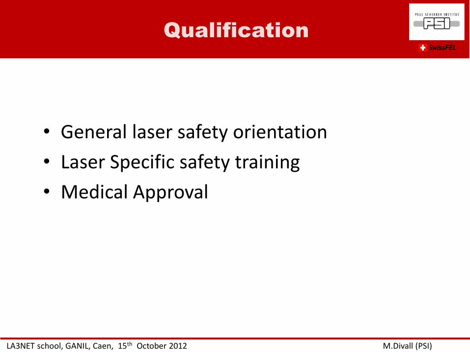
LA3NET school, GANIL, Caen, 15th October 2012 M.Divall (PSI)
SwissFEL
• General laser safety orientation
• Laser Specific safety training
• Medical Approval
Requirements
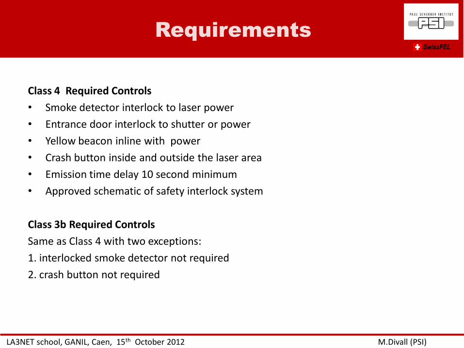
LA3NET school, GANIL, Caen, 15th October 2012 M.Divall (PSI)
SwissFEL
Class 4 Required Controls
• Smoke detector interlock to laser power
• Entrance door interlock to shutter or power
• Yellow beacon inline with power
• Crash button inside and outside the laser area
• Emission time delay 10 second minimum
• Approved schematic of safety interlock system
Class 3b Required Controls
Same as Class 4 with two exceptions:
1. interlocked smoke detector not required
2. crash button not required

Calculations for specific laser
system SwissFEL
LA3NET school, GANIL, Caen, 15th October 2012 M.Divall (PSI)
Homework clue!
LA3NET school, GANIL, Caen, 15th October 2012 M.Divall (PSI)
No clues SwissFEL
THINK ABOUT IT! WHERE DOES THE BEAM GO?
DO YOU HAVE GOSTS?
TAKE CARE OF OTHERS YOU WORK WITH!
MOST ACCIDENTS HAPPEN DURING ALIGNMENT!
10/16/2012 PSI 66 Thank you for your attention!!
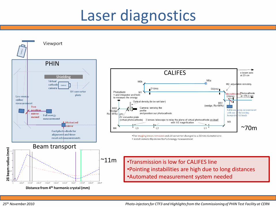
Laser diagnostics
Distance from 4th harmonic crystal (mm)
Beam transport
~11m
PHIN
CALIFES
~70m
•Transmission is low for CALIFES line •Pointing instabilities are high due to long distances •Automated measurement system needed
25th November 2010 Photo-injectors for CTF3 and Highlights from the Commissioning of PHIN Test Facility at CERN
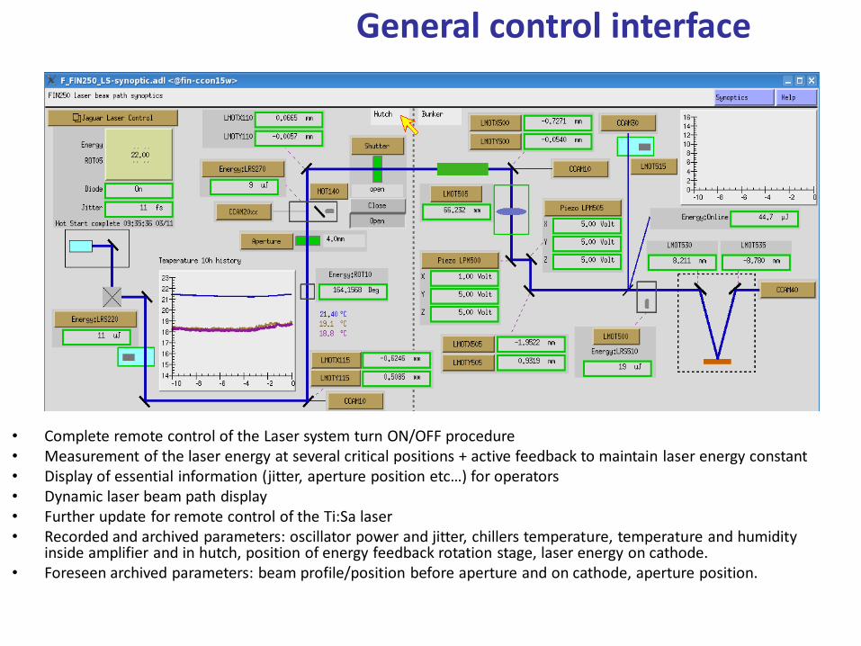
General control interface
• Complete remote control of the Laser system turn ON/OFF procedure • Measurement of the laser energy at several critical positions + active feedback to maintain laser energy constant • Display of essential information (jitter, aperture position etc…) for operators • Dynamic laser beam path display • Further update for remote control of the Ti:Sa laser • Recorded and archived parameters: oscillator power and jitter, chillers temperature, temperature and humidity
inside amplifier and in hutch, position of energy feedback rotation stage, laser energy on cathode. • Foreseen archived parameters: beam profile/position before aperture and on cathode, aperture position.


![Crosslinking of Polymer Beam - Indico [Home]](https://img.pdfslide.us/doc/110x75/61585adea0be3c4b5e49992f/crosslinking-of-polymer-beam-indico-home.jpg)