Embed Size (px)
DESCRIPTION
Beam Line Status. Topics to be Addressed. 4. 4. COBRA End-Cap & Insertion + Drive System Status. 3. 3. COBRA/BTS Fringe Field Beam alignment influence. Degrader Commissioning Run Results. 1. 2. 2. COBRA He-atmosphere. 5. 5. - Beam Test BTS. 6. - PowerPoint PPT Presentation
Citation preview

MEG Review Meeting June 2006MEG Review Meeting June 2006 11Peter-Raymond KettlePeter-Raymond Kettle
Beam Beam LineLine StatusStatus
Beam Beam LineLine StatusStatus

MEG Review Meeting June 2006MEG Review Meeting June 2006 22Peter-Raymond KettlePeter-Raymond Kettle
1.1. Degrader Degrader Commissioning RunCommissioning Run ResultsResults
1.1. Degrader Degrader Commissioning RunCommissioning Run ResultsResults
Topics to be AddressedTopics to be AddressedTopics to be AddressedTopics to be Addressed
2. COBRA 2. COBRA He-atmosphereHe-atmosphere
2. COBRA 2. COBRA He-atmosphereHe-atmosphere
3. COBRA/BTS 3. COBRA/BTS Fringe Field Fringe Field
Beam alignmentBeam alignment influenceinfluence
3. COBRA/BTS 3. COBRA/BTS Fringe Field Fringe Field
Beam alignmentBeam alignment influenceinfluence
5.5. - Beam Test BTS- Beam Test BTS5.5. - Beam Test BTS- Beam Test BTS
4. COBRA End-Cap4. COBRA End-Cap& Insertion + Drive& Insertion + Drive
System StatusSystem Status
4. COBRA End-Cap4. COBRA End-Cap& Insertion + Drive& Insertion + Drive
System StatusSystem Status1.1.
2.2.
44..
5.5.
3.3.
6.6... Target SystemTarget System

MEG Review Meeting June 2006MEG Review Meeting June 2006 33Peter-Raymond KettlePeter-Raymond Kettle
Degrader Run StatusDegrader Run Status
Total 5 weeks planned:Total 5 weeks planned: Many Problems encountered & several SurprisesMany Problems encountered & several Surprises However: some interesting facts learned !!!However: some interesting facts learned !!! Goal:Goal:
• first time measurement of Beam in COBRA with Degraderfirst time measurement of Beam in COBRA with Degrader System deployed at the centre of BTSSystem deployed at the centre of BTS
• understand misalignment problem seen Dec. 2005understand misalignment problem seen Dec. 2005
Complications:Complications:
First time 6cm Target E employed during MEG Commissioning timeFirst time 6cm Target E employed during MEG Commissioning time Lost more than 2 weeks of real beam timeLost more than 2 weeks of real beam time 11 days11 days due to accelerator due to accelerator 2 days2 days due to controller problems 3-D scanner due to controller problems 3-D scanner 1 day1 day control computer problems BTS control computer problems BTS 1 day1 day Separator vacuum interlock problems Separator vacuum interlock problems Measurements stopped Measurements stopped 4 last days4 last days lost due to interference COBRA stray lost due to interference COBRA stray field with other Users beam lines field with other Users beam lines µSR µSR M3 (LTF, GPS) M3 (LTF, GPS) E3 µCap-Expt.E3 µCap-Expt.
Run Programme SHORTENED Could Not Finish everything !!!Run Programme SHORTENED Could Not Finish everything !!!
MEG Review Meeting June 2006MEG Review Meeting June 2006 44Peter-Raymond KettlePeter-Raymond Kettle
11st st Surprise: Missing RateSurprise: Missing Rate from 6 cm Target!from 6 cm Target!
PP
µµ
AHWAHW
AHUAHU
AHVAHV
RR4cm4cm=(0.55=(0.55±0.05)R±0.05)R6cm 6cm (1.8)(1.8) Measured Measured L. Simons et al L. Simons et al
(Pions!!!)(Pions!!!)from geometry alone would expect ~ from geometry alone would expect ~ 0.67 (1.5)0.67 (1.5)
RR4cm4cm=(0.55=(0.55±0.05)R±0.05)R6cm 6cm (1.8)(1.8) Measured Measured L. Simons et al L. Simons et al
(Pions!!!)(Pions!!!)from geometry alone would expect ~ from geometry alone would expect ~ 0.67 (1.5)0.67 (1.5)
Very PROVISIONAL !!!Very PROVISIONAL !!!Measured RMeasured R6cm6cm~ 1.24 R~ 1.24 R4cm4cm
With slits openWith slits open
However: - at 1.8mAHowever: - at 1.8mA
6cm Target6cm Target ~ 1.1 ~ 1.1·10·1099 e e++/s at/s at
4cm Target ~ 7.74cm Target ~ 7.7·10·1088 e e++/s at/s at factor 1.38factor 1.38** Naïve Model could explain** Naïve Model could explainmissing µmissing µ++ rate **: rate **:Surface µSurface µ++ Target Surface Target Surfacee+ e+ Target Volume Target Volume
Low energy Low energy -production X-sections -production X-sections rel. stop density factors rel. stop density factors back face/side face/front face = 3.3/2.5/1.7back face/side face/front face = 3.3/2.5/1.7Low energy Low energy -production X-sections -production X-sections rel. stop density factors rel. stop density factors back face/side face/front face = 3.3/2.5/1.7back face/side face/front face = 3.3/2.5/1.7
ProjectedProjectedIntensityIntensity distdist.. (surface)(surface)
Target ETarget E4/6 cm4/6 cm
If interpretation Correct If interpretation Correct 6 cm Target BAD for MEG 6 cm Target BAD for MEGDon’t gain Don’t gain µµ++ have ~ 1.4 more background e have ~ 1.4 more background e++
If interpretation Correct If interpretation Correct 6 cm Target BAD for MEG 6 cm Target BAD for MEGDon’t gain Don’t gain µµ++ have ~ 1.4 more background e have ~ 1.4 more background e++
EXPECTEDEXPECTED

MEG Review Meeting June 2006MEG Review Meeting June 2006 55Peter-Raymond KettlePeter-Raymond Kettle
22ndnd Surprise: Beam Misalignment Cause! Surprise: Beam Misalignment Cause!
Bfield measurements with triple-axis Tesla meter & Bfield measurements with triple-axis Tesla meter & BTS showed:BTS showed:
• BTS Bfield asymmetry at symmetric distances from axis of max. 10G BTS Bfield asymmetry at symmetric distances from axis of max. 10G (below axis)(below axis) Equivalent toEquivalent to extra Dipole fieldextra Dipole field• symmetry points above/below axis for equal Bfield ~ 30 cm displaced symmetry points above/below axis for equal Bfield ~ 30 cm displaced (therefore (therefore not error in measurement)not error in measurement)• Area Floor exhibits Area Floor exhibits RemanenceRemanence & & HysterisisHysterisis (remembers if BTS +ve/-ve (remembers if BTS +ve/-ve polarity)polarity) fields very reproducible, max. value on Area Floorfields very reproducible, max. value on Area Floor
Shows iron under the floor !!! which causes field lines to be diverted & Shows iron under the floor !!! which causes field lines to be diverted & alters the alters the symmetry of the solenoidal field at a point which is important for symmetry of the solenoidal field at a point which is important for focusingfocusing
Further field measurements after DC-test – with COBRA & BTS ON !!!Further field measurements after DC-test – with COBRA & BTS ON !!!
Enquired about Hall floor- plans should exist lay-out for 40t/mEnquired about Hall floor- plans should exist lay-out for 40t/m22
• 40 cm thick layer of steel reinforced concrete40 cm thick layer of steel reinforced concrete• steel layer ~ 30 cm thick starts about 10 cm downsteel layer ~ 30 cm thick starts about 10 cm down• high-quality steel but NOT STAINLESS !!!high-quality steel but NOT STAINLESS !!!

MEG Review Meeting June 2006MEG Review Meeting June 2006 66Peter-Raymond KettlePeter-Raymond Kettle
33rdrd Surprise: Muons Prematurely Range-out! Surprise: Muons Prematurely Range-out!
100%100%
50%50%
R~ 1460 mm HeR~ 1460 mm He
TTMATMAT
Expected:Expected: 100% transmission to centre COBRA, 100% transmission to centre COBRA, 50% to ~ end COBRA50% to ~ end COBRAAfter degrader ~21 MeV/c entry to COBRAAfter degrader ~21 MeV/c entry to COBRA
Measured:Measured:Mean Range at COBRA z= -900 mm Mean Range at COBRA z= -900 mm R ~1460 mm He Equiv.R ~1460 mm He Equiv. 235 235 µm CHµm CH22
Extra Material Thickness Extra Material Thickness TTMATMAT~ ~ 900 mm He Equiv. or 145 µm CH900 mm He Equiv. or 145 µm CH22
OR OR 9 % Air Contamination 9 % Air Contamination Know that air back diffusion Know that air back diffusion via leaks problematic as well as via leaks problematic as well as suspect “laminar flow” Mixing!suspect “laminar flow” Mixing! test measurement after DC-Testtest measurement after DC-Test Measure Range CurveMeasure Range Curve post BTS to test Momentumpost BTS to test Momentum hypothesishypothesis
18MeV/c18MeV/c
18 MeV/c18 MeV/c in Hein He

MEG Review Meeting June 2006MEG Review Meeting June 2006 77Peter-Raymond KettlePeter-Raymond Kettle
Beam Test ConclusionsBeam Test Conclusions
• more than 2 weeks of real beam time lost mainly due to the acceleratormore than 2 weeks of real beam time lost mainly due to the accelerator• 6 cm target proved problematic since beam wasn’t as expected &6 cm target proved problematic since beam wasn’t as expected & took time to investigatetook time to investigate• possible explanation for lack of increase in possible explanation for lack of increase in µµ++ rate from 6 cm Target rate from 6 cm Target• if true 6 cm Target No good for MEG signal/noise(eif true 6 cm Target No good for MEG signal/noise(e++) bad) bad• magnetic field anomaly found (Iron in floor) causes BTS field asymmetry magnetic field anomaly found (Iron in floor) causes BTS field asymmetry & beam& beam misalignment (misalignment (further investigation needed)further investigation needed)• good He circulation crucial for MEG – good He circulation crucial for MEG – possible cause of our muons ranging-outpossible cause of our muons ranging-out range curve post degrader & BTS should answer thisrange curve post degrader & BTS should answer this
Need extra Beam Time (4 weeks) with 4 cm Target + DegraderNeed extra Beam Time (4 weeks) with 4 cm Target + Degrader
• Only possible after end July (4cm Target) –start 4cm Target unstable + lowOnly possible after end July (4cm Target) –start 4cm Target unstable + low Current MEGAPIECurrent MEGAPIE• Only possible after COBRA stray field influence on other beams solvedOnly possible after COBRA stray field influence on other beams solved• To Not Delay MEG - has to be when End-Caps mounted – however problemTo Not Delay MEG - has to be when End-Caps mounted – however problem no magnet measuring machine possible therefore NEW APD array Detector no magnet measuring machine possible therefore NEW APD array Detector NEEDED – (presented Tokyo Meeting)NEEDED – (presented Tokyo Meeting)

MEG Review Meeting June 2006MEG Review Meeting June 2006 88Peter-Raymond KettlePeter-Raymond Kettle
Question of Question of Muons Muons “ “Ranging-out”Ranging-out”
Question of Question of Muons Muons “ “Ranging-out”Ranging-out”

MEG Review Meeting June 2006MEG Review Meeting June 2006 99Peter-Raymond KettlePeter-Raymond Kettle
COBRA He-AtmosphereCOBRA He-AtmosphereMeasure Profiles Measure Profiles @ Centre COBRA@ Centre COBRAX X = 11.8 mm = 11.8 mm YY = 12.0 = 12.0XX00 4mm offset 4mm offsetYY0 0 on axison axisRate ~ 8Rate ~ 8·10·1077 µ µ++/s /s at 1.8mA, 6cm Targetat 1.8mA, 6cm Target ~ 64% of muons~ 64% of muons reach centre !!!reach centre !!!
Measure Profiles Measure Profiles @ Centre COBRA@ Centre COBRAX X = 11.8 mm = 11.8 mm YY = 12.0 = 12.0XX00 4mm offset 4mm offsetYY0 0 on axison axisRate ~ 8Rate ~ 8·10·1077 µ µ++/s /s at 1.8mA, 6cm Targetat 1.8mA, 6cm Target ~ 64% of muons~ 64% of muons reach centre !!!reach centre !!!WHY?WHY?WHY?WHY?
1.1. Too much material in beam?Too much material in beam?• Degrader too thick? Degrader too thick? • New beam window >190 micronsNew beam window >190 microns Mylar Mylar • Air contamination in He Air contamination in He !!!!!!
2.2. Momentum too low?Momentum too low?• 6cm Target (transverse offset) 6cm Target (transverse offset) ??????• AHW41 Bending magnet AHW41 Bending magnet measured momentum spectrummeasured momentum spectrum
CheckedCheckedCheckedChecked
CheckedCheckedCheckedChecked
Muons Range-out prematurelyMuons Range-out prematurelyMuons Range-out prematurelyMuons Range-out prematurely

MEG Review Meeting June 2006MEG Review Meeting June 2006 1010Peter-Raymond KettlePeter-Raymond Kettle
Beam Materials & MomentumBeam Materials & Momentum
• Degrader: Degrader: – 33 measurements per foil made – 33 measurements per foil made • New Mylar Window:New Mylar Window: - - 16 measurements of 16 measurements of
sample of same foil made sample of same foil made • Beam Momentum: Beam Momentum: - - Integral & Differential Range CurveIntegral & Differential Range Curve
measured post BTS using 50measured post BTS using 50µm & 100 µm & 100 µmµm Mylar foilsMylar foils
Mylar foilsMylar foils+ Holder+ HolderMylar foilsMylar foils+ Holder+ Holder
APD+ HolderAPD+ HolderAPD+ HolderAPD+ Holder
MEG Review Meeting June 2006MEG Review Meeting June 2006 1111Peter-Raymond KettlePeter-Raymond Kettle
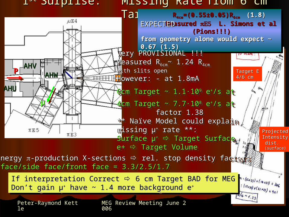
Momentum MeasurementMomentum Measurement
Low Low thresholdthreshold
High High thresholdthreshold
+ 45.5 mm Air+ 20 µm Al foil• Counts Counts µ+eµ+e
• no threshold dependenceno threshold dependence• Michel MS ~ same for allMichel MS ~ same for all measurementsmeasurements
• Counts Counts µ+eµ+e• no threshold dependenceno threshold dependence• Michel MS ~ same for allMichel MS ~ same for all measurementsmeasurements
• Counts Counts µ only (Landau!)µ only (Landau!)• possible threshold dependencepossible threshold dependence
• Counts Counts µ only (Landau!)µ only (Landau!)• possible threshold dependencepossible threshold dependence
TTµµ = (2230 = (2230 ± 60)keV± 60)keV
PPµµ = (21.8 = (21.8 ± 0.3)MeV/c± 0.3)MeV/c
3.8% higher than expected, 3.8% higher than expected,
Possible with 6cm Tg ! Possible with 6cm Tg !
Gives lateral shift – p changeGives lateral shift – p change
TTµµ = (2230 = (2230 ± 60)keV± 60)keV
PPµµ = (21.8 = (21.8 ± 0.3)MeV/c± 0.3)MeV/c
3.8% higher than expected, 3.8% higher than expected,
Possible with 6cm Tg ! Possible with 6cm Tg !
Gives lateral shift – p changeGives lateral shift – p change
MylarRLL= 355 µmRUL= 389 µm
MylarRLL= 355 µmRUL= 389 µm
BEAM MOMENTUM OK !!!

MEG Review Meeting June 2006MEG Review Meeting June 2006 1212Peter-Raymond KettlePeter-Raymond Kettle
COBRA He-atmosphereCOBRA He-atmosphere
TU-1530 He-Monitor (Japan)TU-1530 He-Monitor (Japan)
• Range 0-100% HeRange 0-100% He• accuracy accuracy ±±1 %1 %• Probe part magneticProbe part magnetic
TU-1530 He-Monitor (Japan)TU-1530 He-Monitor (Japan)
• Range 0-100% HeRange 0-100% He• accuracy accuracy ±±1 %1 %• Probe part magneticProbe part magnetic
2 Measurements used as cross-check2 Measurements used as cross-check
Sonic Gas Monitor SGM (home-made)Sonic Gas Monitor SGM (home-made)
• Calibrated Range 92-100% HeCalibrated Range 92-100% He• precision precision ±±0.3 %0.3 %• microphone + speaker magneticmicrophone + speaker magnetic
Sonic Gas Monitor SGM (home-made)Sonic Gas Monitor SGM (home-made)
• Calibrated Range 92-100% HeCalibrated Range 92-100% He• precision precision ±±0.3 %0.3 %• microphone + speaker magneticmicrophone + speaker magnetic

MEG Review Meeting June 2006MEG Review Meeting June 2006 1313Peter-Raymond KettlePeter-Raymond Kettle
He Monitor Cross CalibrationHe Monitor Cross Calibration
HeHeHeHe
AirAirAirAir
Gas Rack (mixer)Gas Rack (mixer)Gas Rack (mixer)Gas Rack (mixer)
True He-mixtureTrue He-mixture
TU-153 TU-153 3.5% 3.5%
SGM SGM 0.2% 0.2%
Measu
red
Conc
Measu
red
Concnn
TU-153 Monitor needs correctionTU-153 Monitor needs correction within 92-100% Range of within 92-100% Range of 3.5% 3.5%TU-153 Monitor needs correctionTU-153 Monitor needs correction within 92-100% Range of within 92-100% Range of 3.5% 3.5%

MEG Review Meeting June 2006MEG Review Meeting June 2006 1414Peter-Raymond KettlePeter-Raymond Kettle
COBRA He-MeasurementsCOBRA He-MeasurementsTU-153 sample He via inserted tubeSampling points:A: SGMA: SGMB: z = + 2085 B: z = + 2085 mmmmC: z = + 705 mmC: z = + 705 mmD: z = + 45 mmD: z = + 45 mmE: z = - 355 mmE: z = - 355 mm
SGMTU-153
AAAA
BBBB
CCCCDDDDEEEE
Pos Comm Run DC Pos Comm Run DC RunRun
B 97% 93%B 97% 93%
C 96% 92%C 96% 92%
D 90% 89%D 90% 89%
E 91% 89%E 91% 89%
Pos Comm Run DC Pos Comm Run DC RunRun
B 97% 93%B 97% 93%
C 96% 92%C 96% 92%
D 90% 89%D 90% 89%
E 91% 89%E 91% 89% He-gradient, worst US !!! He-gradient, worst US !!! • explains ranging-outexplains ranging-out of Muons of Muons• He gas distribution too simpleHe gas distribution too simple• Care with final gas system !!!Care with final gas system !!!
He-gradient, worst US !!! He-gradient, worst US !!! • explains ranging-outexplains ranging-out of Muons of Muons• He gas distribution too simpleHe gas distribution too simple• Care with final gas system !!!Care with final gas system !!!
P r o v i s
i o n a l
7% to11% Air
3% to9% Air

MEG Review Meeting June 2006MEG Review Meeting June 2006 1515Peter-Raymond KettlePeter-Raymond Kettle
Beam MisalignmentBeam Misalignment && BTS + COBRA InfluenceBTS + COBRA Influence
Beam MisalignmentBeam Misalignment && BTS + COBRA InfluenceBTS + COBRA Influence

MEG Review Meeting June 2006MEG Review Meeting June 2006 1616Peter-Raymond KettlePeter-Raymond Kettle
Beam Misalignment/Fringe Field ProblemBeam Misalignment/Fringe Field Problem
Initial field measurements during this run with BTS ONLY showed:
iron under the floor !!!iron under the floor !!! which causes field lines to be diverted & alters the which causes field lines to be diverted & alters the symmetry of the solenoidal field at a point which is important for focusingsymmetry of the solenoidal field at a point which is important for focusing Measurements extended to Final BTS settings + COBRA
Series of measurements done atSeries of measurements done at US & DS faces of BTS withUS & DS faces of BTS withBTS alone & BTS +COBRA:BTS alone & BTS +COBRA:
Asymmetry (beam pipe dia.)Asymmetry (beam pipe dia.)BTS alone:BTS alone:US ~ 6 G, C ~ 7G, DS ~ 5G US ~ 6 G, C ~ 7G, DS ~ 5G
BTS + COBRA:BTS + COBRA:US ~ 6G, C ~ 0.6G, DS ~ 29G US ~ 6G, C ~ 0.6G, DS ~ 29G

MEG Review Meeting June 2006MEG Review Meeting June 2006 1717Peter-Raymond KettlePeter-Raymond Kettle
Radial BTS Symmetry (No COBRA)Radial BTS Symmetry (No COBRA)
US Radial Symmetry Centres
y = -0.0096x2 + 0.0879x - 0.0521
0.000
0.020
0.040
0.060
0.080
0.100
0.120
0.140
0.160
0.180
0 1 2 3 4 5 6 7 8 9
Measurement
Rad
ial O
ffset
[cm
]
US Radial Centres
Poly. (US RadialCentres)
DS Radial Symmetry Centres
y = -0.0141x2 + 0.0783x + 0.2861
0.000
0.050
0.100
0.150
0.200
0.250
0.300
0.350
0.400
0.450
0.500
0 1 2 3 4 5 6 7 8 9
MeasurementRa
dial
Offs
et [c
m]
DS Radial Centres
Poly. (DS RadialCentres)
BTS US Radial Btot Distribution
665.0
670.0
675.0
680.0
685.01
2
3
4
5
6
7
8
9
10
11
12
13
14
15
16
US Radial Data
BTS DS Radial Btot Distribution
660.0
670.0
680.0
690.0
700.0
710.0
720.01
2
3
4
5
6
7
8
9
10
11
12
13
14
15
16DS Radial Data
USUS DSDS
TopTop
BergBerg
AareAare
BotBot
TopTop
BergBerg
AareAare
BotBot
BTS Measured radialBTS Measured radialSymmetry distributionsSymmetry distributionsUS/DS at beam pipe US/DS at beam pipe Diameter I= -200ADiameter I= -200A
v. Simple “c-of-g” v. Simple “c-of-g” interpretationinterpretation Magnetic axis centreMagnetic axis centre
US: r=1.6 mm, US: r=1.6 mm, =292.5=292.5°° Field Asymmetry ~ 11G Field Asymmetry ~ 11G DS: r= 4.5 mm, DS: r= 4.5 mm, =247.5°=247.5° FieldField Asymmetry ~ 33 G Asymmetry ~ 33 G

MEG Review Meeting June 2006MEG Review Meeting June 2006 1818Peter-Raymond KettlePeter-Raymond Kettle
Radial COBRA Asymmetry BTS+COBRARadial COBRA Asymmetry BTS+COBRACOBRA US Radial Btot Distribution
3120.0
3140.0
3160.0
3180.0
3200.0
3220.01
2 34
56
7
8
9
10
11
12
1314
1516
171819
202122
2324
25
26
27
28
29
30
3132
3334
35 36
COBRA RadialAsymmetry
BERGAare
Top
Bott
COBRA Measured radial symmetry COBRA Measured radial symmetry distributiondistributionUS at ~ beam pipe diameterUS at ~ beam pipe diameter
IIBTSBTS= = -203A, -203A, IICOBRACOBRA=360/320A=360/320A
v. Simple “c-of-g” interpretationv. Simple “c-of-g” interpretation Magnetic axis centreMagnetic axis centre
US: r=1.7 mm, US: r=1.7 mm, =240=240°° asymmetry ~ 55G asymmetry ~ 55G Problem to be studied by PSI Magnet Problem to be studied by PSI Magnet Group !!!Group !!!
COBRACOBRAcentrecentre
COBRACOBRAcentrecentre
Influence on Influence on µ-Beamµ-Beam
COBRA Beam Centroid COBRA Beam Centroid ExcursionExcursion
MEG Review Meeting June 2006MEG Review Meeting June 2006 1919Peter-Raymond KettlePeter-Raymond Kettle
COBRA End-Cap COBRA End-Cap ++ Insertion & Drive SystemInsertion & Drive System
COBRA End-Cap COBRA End-Cap ++ Insertion & Drive SystemInsertion & Drive System

MEG Review Meeting June 2006MEG Review Meeting June 2006 2020Peter-Raymond KettlePeter-Raymond Kettle
COBRA US End-Cap SystemCOBRA US End-Cap System
USUSUSUS DSDSDSDS
US End-Cap scheduleUS End-Cap schedule Bieri Engineering manufacture costs ~ 55 kCHfBieri Engineering manufacture costs ~ 55 kCHf
delivery to PSI – THIS WEEK (2 weeks late)delivery to PSI – THIS WEEK (2 weeks late)

MEG Review Meeting June 2006MEG Review Meeting June 2006 2121Peter-Raymond KettlePeter-Raymond Kettle
Insertion SystemInsertion System
Connects to acceleratorConnects to acceleratorBeam pipeBeam pipe
Gliding supportGliding supportringsrings
NBRNBR
RETRACTED into End-CapRETRACTED into End-Cap
ReplaceReplacewithwithwindowwindow
• Gas-tight to He-side CHGas-tight to He-side CH22/EVAL window/EVAL window• normally connected to motor-driven accelerator normally connected to motor-driven accelerator beam tubebeam tube• frictional hand-drive via electric drill/crank-handlefrictional hand-drive via electric drill/crank-handle
Detailed FEM study
Electric-drill or hand driveElectric-drill or hand drive
View from InsideCOBRA

MEG Review Meeting June 2006MEG Review Meeting June 2006 2222Peter-Raymond KettlePeter-Raymond Kettle
COBRA DS End-Cap + Insertion & Drive COBRA DS End-Cap + Insertion & Drive SystemsSystems
Complication encountered with DS End-Cap + Insertion & Drive System:Complication encountered with DS End-Cap + Insertion & Drive System:
Offer received from Bieri Engineering ~ 200kCHf !!!
• successful negotiations with PSI Management for extra money• MEG project raised to priority 1 again – hence PSI workshops can take-over assembly & testing of complete system … Bieri price now ~ 140 kCHf
Delivery schedule: End-August DS End-Cap (as planned but v. tight)Delivery schedule: End-August DS End-Cap (as planned but v. tight) Mid-September Insertion & Drive SystemMid-September Insertion & Drive System
MEG Review Meeting June 2006MEG Review Meeting June 2006 2323Peter-Raymond KettlePeter-Raymond Kettle
BTS BTS
-Beam Test-Beam Test
BTS BTS
-Beam Test-Beam Test

MEG Review Meeting June 2006MEG Review Meeting June 2006 2424Peter-Raymond KettlePeter-Raymond Kettle
BTS Pion Beam TestBTS Pion Beam Test11st st MEG MEG -beam Studies in 2004:-beam Studies in 2004:
• part of momentum spectrum studypart of momentum spectrum study 25-33 MeV/c25-33 MeV/c• dedicated runs at 56 MeV/c & 103 MeV/cdedicated runs at 56 MeV/c & 103 MeV/c• CEX run in CEX run in E5 at 112 MeV/c Oct. 2004E5 at 112 MeV/c Oct. 2004
ALL BEFORE BTS ARRIVED!!!ALL BEFORE BTS ARRIVED!!!
Problem:Problem: BTS cannot be excited to transmit BTS cannot be excited to transmit Momenta >> 70 MeV/c since Momenta >> 70 MeV/c since • maximum Imaximum IBTS BTS ~ 270 A~ 270 A• exceeds allowed force on COBRA coilsexceeds allowed force on COBRA coils
ResultsResults -- Integral Spot Rates in MHzIntegral Spot Rates in MHzfor 1,8mA Proton Current & 4cm Target Efor 1,8mA Proton Current & 4cm Target E
Measured UPSTREAM of BTS positionMeasured UPSTREAM of BTS position Normalized to Momentum Slit Settings:Normalized to Momentum Slit Settings: FS41L/R 250/280 FS43L/R 240/220FS41L/R 250/280 FS43L/R 240/220
56 MeV/c 56 MeV/c RR = 7.6 = 7.6 ·10·1066 --/s/s slits open slits open
RR = 7.2 = 7.2 ·10·1055 --/s slits70/70/s slits70/7056 MeV/c 56 MeV/c RR = 7.6 = 7.6 ·10·1066 --/s/s slits open slits open
RR = 7.2 = 7.2 ·10·1055 --/s slits70/70/s slits70/70
Solution:Solution: - should be able to transmit - should be able to transmit56 Mev/c particles (2*28 MeV/c) with56 Mev/c particles (2*28 MeV/c) withGood optics Good optics
Solution:Solution: - should be able to transmit - should be able to transmit56 Mev/c particles (2*28 MeV/c) with56 Mev/c particles (2*28 MeV/c) withGood optics Good optics
Single NodeSingle NodeSNMSNM
Single NodeSingle NodeSNMSNM
Double NodeDouble NodeDNMDNM
Double NodeDouble NodeDNMDNM
56 MeV/c56 MeV/c56 MeV/c56 MeV/c
28 MeV/c28 MeV/c28 MeV/c28 MeV/c
MeasuredMeasuredUS BTSUS BTS

MEG Review Meeting June 2006MEG Review Meeting June 2006 2525Peter-Raymond KettlePeter-Raymond Kettle
BTS BTS -Beam Test cont.-Beam Test cont.BTS test done last week:BTS test done last week:
Problem encountered – Hamamatsu APD Problem encountered – Hamamatsu APD used for used for µµ++ (no scint. but utilize “Nuclear Counter Effect”) (no scint. but utilize “Nuclear Counter Effect”) • has no pulse-ht. resolution for has no pulse-ht. resolution for -- CANNOT DISTINGUISH e CANNOT DISTINGUISH e- - & & --
• measured at 56 MeV/C & 107 MeV/c with APD & Pill Counter (scintillator)measured at 56 MeV/C & 107 MeV/c with APD & Pill Counter (scintillator) see pions & electrons with pill-countersee pions & electrons with pill-counter BUT CANNOT USE WITH BTS BFIELDBUT CANNOT USE WITH BTS BFIELD
HOWEVER:HOWEVER: COULD TRANSMIT 56 MeV/c PARTICLES as expectedCOULD TRANSMIT 56 MeV/c PARTICLES as expected
BTS Excitation CurveBTS Excitation CurveFor 56 MeV/cFor 56 MeV/cparticlesparticles
Question:Question:
What are expected low-energyWhat are expected low-energy Pion Beam Rates at centre of COBRA?Pion Beam Rates at centre of COBRA?
Question:Question:
What are expected low-energyWhat are expected low-energy Pion Beam Rates at centre of COBRA?Pion Beam Rates at centre of COBRA?
MEG Review Meeting June 2006MEG Review Meeting June 2006 2626Peter-Raymond KettlePeter-Raymond Kettle
BTS BTS -Beam Test cont.-Beam Test cont.
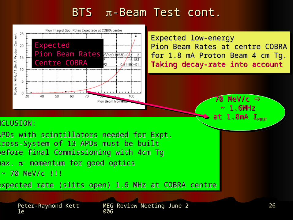
CONCLUSION:CONCLUSION:
• APDs with scintillators needed for Expt.APDs with scintillators needed for Expt. Cross-System of 13 APDs must be built Cross-System of 13 APDs must be built before final Commissioning with 4cm Tgbefore final Commissioning with 4cm Tg• max. max. -- momentum for good opticsmomentum for good optics
~ 70 MeV/c !!!~ 70 MeV/c !!!
• expected rate (slits open) 1.6 MHz at COBRA centreexpected rate (slits open) 1.6 MHz at COBRA centre
Expected low-energy Expected low-energy Pion Beam Rates at centre COBRAPion Beam Rates at centre COBRAfor 1.8 mA Proton Beam 4 cm Tg.for 1.8 mA Proton Beam 4 cm Tg.Taking decay-rate into accountTaking decay-rate into account
Expected low-energy Expected low-energy Pion Beam Rates at centre COBRAPion Beam Rates at centre COBRAfor 1.8 mA Proton Beam 4 cm Tg.for 1.8 mA Proton Beam 4 cm Tg.Taking decay-rate into accountTaking decay-rate into account
ExpectedExpectedPion Beam RatesPion Beam RatesCentre COBRACentre COBRA
70 MeV/c 70 MeV/c ~ 1.6MHz ~ 1.6MHz
at 1.8mA Iat 1.8mA IPROTPROT
70 MeV/c 70 MeV/c ~ 1.6MHz ~ 1.6MHz
at 1.8mA Iat 1.8mA IPROTPROT

MEG Review Meeting June 2006MEG Review Meeting June 2006 2727Peter-Raymond KettlePeter-Raymond Kettle
Target SystemTarget System
UCI UCI
Target SystemTarget System
UCI UCI
MEG Review Meeting June 2006MEG Review Meeting June 2006 2828Peter-Raymond KettlePeter-Raymond Kettle
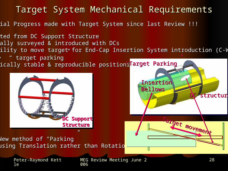
Target System Mechanical RequirementsTarget System Mechanical Requirements
Substantial Progress made with Target System since last Review !!!Substantial Progress made with Target System since last Review !!!
• Supported from DC Support StructureSupported from DC Support Structure• externally surveyed & introduced with DCsexternally surveyed & introduced with DCs• possibility to move target for End-Cap Insertion System introduction (C-W, LHpossibility to move target for End-Cap Insertion System introduction (C-W, LH22,…),…)
“ “ target parking”target parking”• Mechanically stable & reproducible positioningMechanically stable & reproducible positioning
DC Support DC Support StructureStructure
InsertionInsertionBellowsBellows
DC structureDC structure
““Target Parking”Target Parking”
New method of “Parking” New method of “Parking” using Translation rather than Rotationusing Translation rather than Rotation
Target movement
Target movement

MEG Review Meeting June 2006MEG Review Meeting June 2006 2929Peter-Raymond KettlePeter-Raymond Kettle
Target System CharacteristicsTarget System Characteristics
Present Target Characteristics:Present Target Characteristics:
• Ellipse (210 x 70)mm Polyester foil 175 Ellipse (210 x 70)mm Polyester foil 175 µmµm• freely suspended by support pins from afreely suspended by support pins from a thin Rohacell support frame at ~22thin Rohacell support frame at ~22° to axis° to axis (differential expansion)(differential expansion)• frame attached by Rohacell support stemsframe attached by Rohacell support stems mounted on v. thin movable rodsmounted on v. thin movable rods• Driven by pneumatic driveDriven by pneumatic drive
polyesterpolyesterpolyesterpolyester
RohacellRohacell
DC SupportDC SupportPneumaticPneumatic DriveDrive
MovementMovement
Current Status UCI:Current Status UCI:
• prototype system prototype system successfully testedsuccessfully tested
Final SystemFinal System
• All parts machinedAll parts machined• Assembly & testing about Assembly & testing about to startto start• target foil material & angletarget foil material & angle still under studystill under study

MEG Review Meeting June 2006MEG Review Meeting June 2006 3030Peter-Raymond KettlePeter-Raymond Kettle
Prototype Target & PerformancePrototype Target & Performance
Test Setup UCITest Setup UCI
Pins on which Pins on which film is hungfilm is hung
Screws for Screws for clamping clamping
frameframe
Rohacell FrameRohacell Frame
DC SupportDC Support TubeTube
Thin film (~175 micron) target – material to be determinedThin film (~175 micron) target – material to be determined““soft” polyethylene too difficult to maintain flatsoft” polyethylene too difficult to maintain flatVarious polyester, polystyrene, “hard” polyethylene materials possibleVarious polyester, polystyrene, “hard” polyethylene materials possible
Implementation Implementation Target flatness controlled by Rohacell frame – clamping two frames Target flatness controlled by Rohacell frame – clamping two frames
together allows control of flatnesstogether allows control of flatnessHanging film between frames Hanging film between frames allows for differential expansion allows for differential expansion without deformation of filmwithout deformation of filmDistance between frames controlled Distance between frames controlled by washers at screw locations by washers at screw locations Final frame cut precisely with high Final frame cut precisely with high speed CNC routerspeed CNC routerNylon screws/nuts used to reduce massNylon screws/nuts used to reduce mass

MEG Review Meeting June 2006MEG Review Meeting June 2006 3131Peter-Raymond KettlePeter-Raymond Kettle
Prototype Target & Performance cont.Prototype Target & Performance cont. Flatness measured by reflected laser off target surface and measuring Flatness measured by reflected laser off target surface and measuring
reflected angle as laser spot is scanned across target.reflected angle as laser spot is scanned across target. Z(x,y) = Z(0,0) + Z(x,y) = Z(0,0) + ∫ (dz/dx)dx + ∫(dz/dy)dy∫ (dz/dx)dx + ∫(dz/dy)dy
Target measured to be flat to less than +/-100 micronsTarget measured to be flat to less than +/-100 microns
x y anglethicknessmicron % mu stops
21 7.7 21.8 150 64.721 7.7 21.8 175 69.6221 6 21.8 175 68.7521 5 21.8 175 66.7220 5 21.8 175 66.0719 5 21.8 175 65.5619 4 21.8 175 60.5621 5 0 175 45.4521 5 5 175 52.5721 5 10 175 62.2321 5 15 175 67.4925 5 5 175 57.0425 5 10 175 67.9925 5 15 175 70.3425 4 15 175 64.2830 4 15 175 66.1335 4 15 175 66.76
Target Size Study
Measured 45° target Measured 45° target 88% stops 88% stopsSlanted target gives “leakage” due to MSSlanted target gives “leakage” due to MS
Relatively insensitive to vertical size down to Relatively insensitive to vertical size down to 5.7cm 5.7cm Relatively insensitive to length down to 19 cm Relatively insensitive to length down to 19 cm HOWEVERHOWEVER Thickness of 175 microns required Thickness of 175 microns requiredFinal Parameters + slope sense still under Final Parameters + slope sense still under studystudy

MEG Review Meeting June 2006MEG Review Meeting June 2006 3232Peter-Raymond KettlePeter-Raymond Kettle
ScheduleSchedule US End-Cap:US End-Cap:• Delivery US COBRA End-Cap: Delivery US COBRA End-Cap: end Juneend June• US End-Cap preparations mounting PSI workshops US End-Cap preparations mounting PSI workshops 6WD installation after US TC6WD installation after US TC• US End-Cap installation US End-Cap installation 5WD Beg. Sept.5WD Beg. Sept.
Target System:Target System:• Production Production End JulyEnd July• Target assembly + installation Target assembly + installation 2W2W
DS End-Cap + Insertion & Drive System:DS End-Cap + Insertion & Drive System:• Delivery DS COBRA End-Cap Delivery DS COBRA End-Cap End Aug. – Mid Sept.End Aug. – Mid Sept.• Delivery Insertion + Drive System Delivery Insertion + Drive System Mid Sept. Mid Sept. • DS End-Cap preparations mounting PSI workshops DS End-Cap preparations mounting PSI workshops 6WD installation after DS TC6WD installation after DS TC• Insertion & Drive SystemInsertion & Drive System mounting + testing PSI workshops mounting + testing PSI workshops 6WD6WD• DS End-Cap + Insertion & Drive System installation DS End-Cap + Insertion & Drive System installation 10WD End. Sept.10WD End. Sept.
Beam Commissioning (degrader + 4cm Tg.)Beam Commissioning (degrader + 4cm Tg.)• Beam Line setup + survey Beam Line setup + survey 5WD post US End-Cap Beg. Sept.5WD post US End-Cap Beg. Sept.• BTS cryo-connections + pump & cool-down BTS cryo-connections + pump & cool-down 8WD8WD• Beam Commissioning Run Beam Commissioning Run 4Weeks Beg. Oct.4Weeks Beg. Oct.• Pion Beam Tune CEX Pion Beam Tune CEX 7D (if not during Comm. Run) before LXe Calib. Mid. Dec.7D (if not during Comm. Run) before LXe Calib. Mid. Dec.