Embed Size (px)
Citation preview

BeagleBoard-xM LCD7 System Reference Manual Revision B
Page 1 of 27
BeagleBoard-xM LCD7 Rev B
System Reference Manual
November 1st, 2012
BeagleBoard-xM LCD7 System Reference Manual Revision B
Page 2 of 27
THIS DOCUMENT
This work is licensed under the Creative Commons Attribution-Share Alike 3.0 Unported License. To view a copy of this license, visit http://creativecommons.org/licenses/by-sa/3.0/ or send a letter to Creative Commons, 171 Second Street, Suite 300, San Francisco, California, 94105, USA. All derivative works are to be attributed to BeagleBoardtoys.com. For more information, see http://creativecommons.org/license/results-one?license_code=by-sa For any questions, concerns, or issues submit them to [email protected]
BEAGLEBOARD-XM LCD7 DESIGN These design materials referred to in this document are *NOT SUPPORTED* and DO NOT constitute a reference design. Only “community” support is allowed via resources at Beagleboardtoys.com/support THERE IS NO WARRANTY FOR THE DESIGN MATERIALS, TO THE EXTENT PERMITTED BY APPLICABLE LAW. EXCEPT WHEN OTHERWISE STATED IN WRITING THE COPYRIGHT HOLDERS AND/OR OTHER PARTIES PROVIDE THE DESIGN MATERIALS “AS IS” WITHOUT WARRANTY OF ANY KIND, EITHER EXPRESSED OR IMPLIED, INCLUDING, BUT NOT LIMITED TO, THE IMPLIED WARRANTIES OF MERCHANTABILITY AND

BeagleBoard-xM LCD7 System Reference Manual Revision B
Page 3 of 27
FITNESS FOR A PARTICULAR PURPOSE. THE ENTIRE RISK AS TO THE QUALITY AND PERFORMANCE OF THE DESIGN MATERIALS IS WITH YOU. SHOULD THE DESIGN MATERIALS PROVE DEFECTIVE, YOU ASSUME THE COST OF ALL NECESSARY SERVICING, REPAIR OR CORRECTION. We mean it; these design materials may be totally unsuitable for any purposes.

BeagleBoard-xM LCD7 System Reference Manual Revision B
Page 4 of 27
BeagleBoardToys provides the enclosed product(s) under the following conditions: This evaluation board/kit is intended for use for ENGINEERING DEVELOPMENT, DEMONSTRATION, OR EVALUATION PURPOSES ONLY and is not considered by BeagleBoardtoys.com to be a finished end-product fit for general consumer use. Persons handling the product(s) must have electronics training and observe good engineering practice standards. As such, the goods being provided are not intended to be complete in terms of required design-, marketing-, and/or manufacturing-related protective considerations, including product safety and environmental measures typically found in end products that incorporate such semiconductor components or circuit boards. This evaluation board/kit does not fall within the scope of the European Union directives regarding electromagnetic compatibility, restricted substances (RoHS), recycling (WEEE), FCC, CE or UL, and therefore may not meet the technical requirements of these directives or other related directives. Should this evaluation board/kit not meet the specifications indicated in the User’s Guide, the board/kit may be returned within 30 days from the date of delivery for a full refund. THE FOREGOING WARRANTY IS THE EXCLUSIVE WARRANTY MADE BY SELLER TO BUYER AND IS IN LIEU OF ALL OTHER WARRANTIES, EXPRESSED, IMPLIED, OR STATUTORY, INCLUDING ANY WARRANTY OF MERCHANTABILITY OR FITNESS FOR ANY PARTICULAR PURPOSE. The user assumes all responsibility and liability for proper and safe handling of the goods. Further, the user indemnifies BeagleBoardtoys.com from all claims arising from the handling or use of the goods. Due to the open construction of the product, it is the user’s responsibility to take any and all appropriate precautions with regard to electrostatic discharge. EXCEPT TO THE EXTENT OF THE INDEMNITY SET FORTH ABOVE, NEITHER PARTY SHALL BE LIABLE TO THE OTHER FOR ANY INDIRECT, SPECIAL, INCIDENTAL, OR CONSEQUENTIAL DAMAGES. BeagleBoardtoys.com currently deals with a variety of customers for products, and therefore our arrangement with the user is not exclusive. BeagleBoardtoys.com assumes no liability for applications assistance, customer product design, software performance, or infringement of patents or services described herein. Please read the User’s Guide and, specifically, the Warnings and Restrictions notice in the User’s Guide prior to handling the product. This notice contains important safety information about temperatures and voltages. For additional information on BeagleBoardtoys.com environmental and/or safety programs, please contact visit BeagleBoardtoys.com. No license is granted under any patent right or other intellectual property right of BeagleBoard.org covering or relating to any machine, process, or combination in which such BeagleBoardtoys.com products or services might be or are used. Mailing Address:
Beagleboardtoys.com 1380 Presidential Dr. #100 Richardson, TX 75081 U.S.A.

BeagleBoard-xM LCD7 System Reference Manual Revision B
Page 5 of 27
WARRANTY: The BeagleBoard-xM LCD7 is warranted against defects in materials and workmanship for a period of 90 days from purchase. This warranty does not cover any problems occurring as a result of improper use, modifications, exposure to water, excessive voltages, abuse, or accidents. All boards will be returned via standard mail if an issue is found. If no issue is found or express return is needed, the customer will pay all shipping costs.
Before returning the board, please visit Beagleboardtoys.com/support To return a defective board, please request an RMA at http://www.beagleboardtoys.com/support/rma

BeagleBoard-xM LCD7 System Reference Manual Revision B
Page 6 of 27
Table of Contents FIGURES ...................................................................................................................................................... 7
TABLES ........................................................................................................................................................ 7
1.0 INTRODUCTION............................................................................................................................... 9
2.0 CHANGE HISTORY .........................................................................................................................10
2.1 CHANGE HISTORY ............................................................................................................................10 2.2 A VS. B ............................................................................................................................................10
3.0 BEAGLEBOARD-XM LCD7 CAPE OVERVIEW ................. .......................................................11
3.1 DESCRIPTIONS..................................................................................................................................11 3.2 IN THE BOX .....................................................................................................................................12 3.3 GETTING STARTED ...........................................................................................................................12 3.4 REPAIRS ...........................................................................................................................................12
4.0 FEATURES AND SPECIFICATIONS ............................................................................................13
4.1 KEY COMPONENT LOCATIONS .........................................................................................................14 4.2 LCD PANEL .....................................................................................................................................15 4.3 INDICATORS .....................................................................................................................................15 4.4 EXPANSION CONNECTORS ................................................................................................................15 4.5 SWITCHES ........................................................................................................................................15 4.6 DC POWER CONNECTOR ..................................................................................................................15 4.7 MECHANICAL SPECIFICATIONS ........................................................................................................16 4.8 ELECTRICAL SPECIFICATIONS ..........................................................................................................16
5.0 SYSTEM ARCHITECTURE AND DESIGN ..................................................................................17
5.1 SYSTEM BLOCK DIAGRAM ...............................................................................................................17 5.2 LCD INTERFACE ..............................................................................................................................18
5.2.1 Expansion connectors ............................................................................................................18 5.2.2 Non-Inverting Bus Transceiver ..............................................................................................19 5.2.3 Touchscreen Interface ...........................................................................................................20
5.3 POWER MANAGEMENT.....................................................................................................................20 5.3.1 LCD Power Supply ................................................................................................................20 5.3.2 Backlight Power Supply .........................................................................................................22 5.3.3 LCD Control Signals .............................................................................................................23
5.4 EEPROM ........................................................................................................................................24
6.0 MECHANICAL INFORMATION ............................ .......................................................................26
7.0 DESIGN MATERIALS .....................................................................................................................27

BeagleBoard-xM LCD7 System Reference Manual Revision B
Page 7 of 27
Figures Figure 1. The BeagleBoard-xM LCD7 board .............................................................. 11 Figure 2. Key Components on BeagleBoard-xM LCD7 .............................................. 14 Figure 3. BeagleBoard-xM LCD7 High Level Block Diagram ................................... 17 Figure 4. LCD interface at dual LCD connectors ........................................................ 18
Figure 5. LCD Signals buffered through U3 ................................................................ 19 Figure 6. BeagleBoard-xM LCD7 Power Management IC .......................................... 21 Figure 7. BeagleBoard-xM LCD7 Backlight Circuit ................................................... 23 Figure 8. BeagleBoard-xM LCD7 Backlight Circuit ................................................... 24 Figure 9. BeagleBoard-xM LCD7 Cape EEPROM ..................................................... 25
Figure 10. BeagleBoard-xM LCD7 Dimensions Drawing ......................................... 26
Tables Table 1. Change History ............................................................................................. 10 Table 2. BeagleBoard-xM LCD7 Cape Features ........................................................ 13

BeagleBoard-xM LCD7 System Reference Manual Revision B
Page 8 of 27
NOTES

BeagleBoard-xM LCD7 System Reference Manual Revision B
Page 9 of 27
1.0 Introduction This document is the System Reference Manual for the BeagleBoard-xM LCD7, an add-on board for the BeagleBoard-xM. This document is intended as a guide to assist anyone purchasing or who are considering purchasing the board to understand the overall design and usage of the BeagleBoard-xM LCD7 from the system level perspective. The design is subject to change without notice as we will work to keep improving the design as the product matures. The key sections in this document are: Section 2.0 – Change History
Provides tracking for the changes made to the System Reference Manual. Section 3.0 – Overview This is a high level overview of the BeagleBoard-xM LCD7. Section 4.0 – Features and Specification Provided here are the features and electrical specifications of the board. Section 5.0 – System Architecture and Design
This section provides information on the overall architecture and design of the BeagleBoard-xM LCD7. This is a very detailed section that goes into the design of each circuit on the board.
Section 6.0 – Mechanical Information is provided here on the dimensions of the BeagleBoard-xM LCD7. Section 7.0 – Design Materials
This section provides information on where to get the design files.

BeagleBoard-xM LCD7 System Reference Manual Revision B
Page 10 of 27
2.0 Change History 2.1 Change History Table 1 tracks the changes made for each revision of this document.
Table 1. Change History
Rev Changes Date By A Initial release. 10/14/2011 BBT
B
1. Backlight circuit modified. 2. LCD EDID EEPROM removed 3. GND testpoint TP3 added 4. PCB is now 4-layered
11/01/2012 BBT
2.2 A vs. B In revision B, the backlight circuit being modified to provide better current control for the LCD backlight. The LCD EDID EEPROM and support for other platforms have been removed; the board is now called BeagleBoard-xM LCD7 and supports only BeagleBoard-xM. There are also some changes on the PCB; however, these changes are not populated; therefore, they will not affect the performance of the board. The number of PCB layers has been reduced to 4. The PCB revision is changed to BB-XM-LCD7-PCB-01.

BeagleBoard-xM LCD7 System Reference Manual Revision B
Page 11 of 27
3.0 BeagleBoard-xM LCD7 Cape Overview 3.1 Descriptions The BeagleBoard-xM LCD7 provides an LCD solution with touchscreen capability for BeagleBoard-xM boards. The 7" TFT LCD screen, attached to the topside of the board, can display up to a resolution of 800x480 and is a 4-wire resistive touchscreen. The backside of the board is where the BeagleBoard-xM and additional expansion boards can be mounted. The BeagleBoard-xM LCD7 Cape is also equipped with a reset button and a connector footprint for a WiFi expansion connector. Figure 1 below is a picture of the board.
Figure 1. The BeagleBoard-xM LCD7 board

BeagleBoard-xM LCD7 System Reference Manual Revision B
Page 12 of 27
3.2 In The Box The final packaged BeagleBoard-xM LCD7 product will contain the following items:
- 1 BeagleBoard-xM LCD7 with standoffs - 1 wiki information card - 1 bracket information card
3.3 Getting Started Following the instructions below to start using your BeagleBoard-xM LCD7 :
1. Mount the BeagleBoard-xM to the Beagle Expansion connector and LCD dual connectors on the back of the LCD7 board.
• Note: The Beagle Expansion connector is the 28 pin male header on the back of LCD7 board. The LCD dual connectors are two 20 pin male headers also on the back of LCD7 board.
2. Go to the wiki page for the BeagleBoard-xM LCD7 and download the latest Angstrom image http://beagleboardtoys.com/wiki/
3. Follow the instructions on the wiki to write the image file to your SD card. 4. Plug in 5Vsupply to the 5V connector P1 on the LCD7 board. 5. The BeagleBoard-xM is now booting up. This process may take 1-2 minutes 6. After finishing booting up, the Angstrom desktop will be displayed on the LCD
screen. You can start using the board. 3.4 Repairs If you feel the board is in need of repair, follow the RMA Request process found at http://www.beagleboardtoys.com/support/rma
Do not send the board in for repair until an RMA authorization has been provided.
Do not return the board to the distributor unless you want to get a refund. You must get authorization from the distributor before returning the board.

BeagleBoard-xM LCD7 System Reference Manual Revision B
Page 13 of 27
4.0 Features and Specifications This section covers the specifications of the BeagleBoard-xM LCD7 Cape and provides a high level description of the major components and interfaces that make up the board. Table 2 provides a list of the BeagleBoard-xM LCD7 Cape’s features.
Table 2. BeagleBoard-xM LCD7 Cape Features
Feature Display ThreeFive TFC-S9700RTWV35TR-01
LCD Size 7” Panel Type a-Si TFT active matrix Resolution 800 x 480
Colors 16.7M Touch Panel Resistive Color Depth RGB 16-bit
Power Supply 5V DC on board
PCB 4.50” x 6.90” 4 layers
Indicators Power LED
EEPROM Board ID EEPROM
Connectors
28 pin Beagle connector Dual 20-pin LCD connector 28 pin Expansion connector
28 pin WLAN expansion connector (footprint)

BeagleBoard-xM LCD7 System Reference Manual Revision B
Page 14 of 27
4.1 Key Component Locations Figure 2 below shows the locations of key components on the PCB of the BeagleBoard-xM LCD7 Cape:
Figure 2. Key Components on BeagleBoard-xM LCD7

BeagleBoard-xM LCD7 System Reference Manual Revision B
Page 15 of 27
4.2 LCD Panel The LCD Panel is supplied by ThreeFive. The Model number is TFC-S9700RTWV35TR-01. This display uses amorphous silicon (a-Si) as a switching device. This model is composed of a single 7.0 (16:9) inches transmissive type main TFT LCD panel. The resolution is 800x480 and it can display up to 16.7M colors. 4.3 Indicators There is one Power LED indicator (D3) on board. This LED indicates power has been applied to the LCD panel. 4.4 Expansion Connectors J1 is the Beagle Expansion connector to be used with BeagleBoard-xM. This connector is a 28-pin male header that can be mated with the female expansion headers on BeagleBoard-xM. P2 is an expansion connector to be used for an additional cape. This connector is female and has 28 pins. The signals brought out to this connector are the same as the Beagle Expansion connector J1. P10 is a WLAN Expansion connector. Though not populated, this provides an option for customer to install a WLAN daughter card to the BeagleBoard-xM LCD7. 4.5 Switches There is a reset switch (S1) that is populated at 90 degree to the PCB. This button is located on the top right corner when looking down at the LCD screen and is used to reset the main board. 4.6 DC Power Connector A 5V DC power connector P1 is provided onboard. The board can be powered using this power connector or via the mounted BeagleBoard-xM. The connector used is a 2.1mm center positive x 5.5mm outer barrel. Once plugged in, 5V will be provided to the DC_5V power rail, which is also used by the BeagleBoard-xM. Note: The 5V DC power connectors on the BeagleBoard-xM LCD7 and the BeagleBoard-xM should not be used at the same time.
BeagleBoard-xM LCD7 System Reference Manual Revision B
Page 16 of 27
4.7 Mechanical Specifications
Size: 4.50” x 6.90” Layers: 4 PCB thickness: .062”
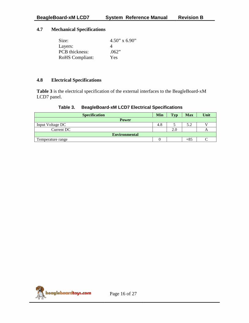
RoHS Compliant: Yes 4.8 Electrical Specifications Table 3 is the electrical specification of the external interfaces to the BeagleBoard-xM LCD7 panel.
Table 3. BeagleBoard-xM LCD7 Electrical Specifications
Specification Min Typ Max Unit Power
Input Voltage DC 4.8 5 5.2 V Current DC 2.0 A
Environmental Temperature range 0 +85 C

BeagleBoard-xM LCD7 System Reference Manual Revision B
Page 17 of 27
5.0 System Architecture and Design This section provides a high level description of the design of the BeagleBoard-xM LCD7 and its overall architecture. 5.1 System Block Diagram Figure 3 is the high level block diagram of the BeagleBoard-xM LCD7.
S2-S6
SWITCHES
D5
RGB LED
U8
TLC59108IPW
BACKLIGHT
DRIVER
RESET
2
I2C2
5
3P2
E
X
P
C
O
N
N
P10
W
L
A
N
E
X
P
13
11
24D[0..23] 24
3
4 VSYNC,HSYNC,DEN,CLK
5MODE/STBYB/UPDN/DITH/MODE3/SHLR
P3
L
C
D
C
O
N
N
U3
74AVC32T245
32-BIT BUFFER
J3
L
C
D
E
X
P
J4
L
C
D
E
X
P
4
TS_nPEN_IRQ
J1
B
E
A
G
L
E
E
X
P
U12
TCA6408A
I2C I/O
EXPANDER
U4
AT24C01
ID EEPROM
U5
TSC2007
TOUCHSCREEN
CONTROLLER
S1
RESET
SWITCH
D5
T/S
CONNECTOR
U7
TXS0102
VOLT
TRANS
U10
SN74LVC1G
BUFFER
U2
TPS65105PWP
POWER
MANAGEMENT
LCD_AVDD_ENAVDD_10V
VGH_15V
VCOM
VGL_-7V
VDD_LCD
D5
T/S
CONNECTOR
U9
TPS61080DRC
DC/DC BOOST
LCD_ENBKL LED+/-
4
D3
POWER
LED
VDD_LCD_BASE
Figure 3. BeagleBoard-xM LCD7 High Level Block Diagram

BeagleBoard-xM LCD7 System Reference Manual Revision B
Page 18 of 27
5.2 LCD Interface 5.2.1 Expansion connectors The LCD interface of the BeagleBoard-xM LCD7 uses 24 data and 4 control signals from the BeagleBoard-xM’s Dual LCD connectors J3 and J4. The 4 control signals are horizontal sync (HSYNC), vertical sync (VSYNC), enable input (DEN), and the pixel clock (CLK). Figure 4 shows these LCD signals at the dual LCD connectors.
Figure 4. LCD interface at dual LCD connectors

BeagleBoard-xM LCD7 System Reference Manual Revision B
Page 19 of 27
5.2.2 Non-Inverting Bus Transceiver The LCD signals are buffered through U3 (74AVC32T245), which is a 32-bit dual-supply bus transceiver. 74AVC32T245 features two ports, A and B. Each port tracks a separate power-supply rail. This allows for universal low-voltage translation. The output-enable (OE) input specifies whether the buses are isolated. The direction-control input, on the other hand, determines the data transmission direction. On the BeagleBoard-xM, since the signals coming out of the expansion header are at 1.8V, power supply of B port is also tracked 1.8V. Signals at A port, on the other hands are supplied by the power rail VDD_LCD (3.3V). Both the direction-control and output-enable inputs are set low, so the data are transmitted from B to A before going to LCD connector P2. Figure 5 shows the LCD signals are buffered through U3.
Figure 5. LCD Signals buffered through U3

BeagleBoard-xM LCD7 System Reference Manual Revision B
Page 20 of 27
5.2.3 Touchscreen Interface The TFC-S9700RTWV35TR-01 touchscreen is resistive is connected to touchscreen connector P6, which is composed of 4 different X or Y signals. These signals are received by the onboard touchscreen controller TSC2007 (U4). When the screen is touched, interrupt output TS_nPEN_IRQ is asserted to dectect the touch. TSC2007 is a low-power touchscreen controller that can operate with supply voltage of 1.8V. TSC2007 supports I2C serial bus and data transmission protocol. Touchscreen data can be transmitted over I2C2 bus to the BeagleBoard-xM. 5.3 Power Management 5.3.1 LCD Power Supply The main Power Management IC (PMIC) in the system is the TPS65105. This PMIC offers a compact and small power supply solution that provides all three voltages required by TFT LCD displays. TPS65105 also has an integrated VCOM buffer to power the LCD backplane as well as a linear regulator controller to provide a 3.3V output for system powered by 5V only. The enable (EN) input of the device is controlled by signal LCD_AVDD_EN, which is exposed at expansion connector J1. For more information about TPS65105, refer to http://www.ti.com/product/tps65105 Figure 6 shows TPS65105 in the system.

BeagleBoard-xM LCD7 System Reference Manual Revision B
Page 21 of 27
Figure 6. BeagleBoard-xM LCD7 Power Management IC The main boost converter of TPS65105 operates with a fixed frequency of 1.6MHz and provides the AVDD_10V power rail for the LCD interface. This output is also fed to SUP pin as an input voltage for positive and negative charge pumps and bias supply for VCOM buffer. The input of the VCOM buffer is VCOMIN pin. If VCOM is not used in a circuit, the buffer can be shut down and the quiescent current can be reduced by grounding the VCOMIN pin. In this case, VCOMIN is connected to a 4V resistive divider of AVDD_10V, which results in VCOM output to be 4V. TPS65105 is also integrated with adjustable positive and negative charge pumps. The input voltage to these charge pumps is the aforementioned AVDD_10V output that is fed to SUP input. These positive and negative outputs are 15Vand -7V, which provide the positive and negative gate drive voltages VGH and VGL of the LCD panel. TPS65105 also provides a linear regulator controller to generate a 3.3V output from a 5V source. This linear regulator controller is independent from the system since it has its own enable input. In the BeagleBoard-xM LCD7, this enable pin is connected to the DC_5V power rail to make sure the controller is always active. An external npn transistor is used, and its base is driven by the Base output from the PMIC. A feedback signal is fed

BeagleBoard-xM LCD7 System Reference Manual Revision B
Page 22 of 27
back to TPS65105 to ensure the transistor’s output is fixed at 3.3V. This voltage is connected to power rail VDD_LCD and also powers the Power LED. The main boost converter of TPS65105 as well as positive and negative charge pumps, linear regulator, and VCOM buffer have an internal soft start. The purpose of soft start is to avoid heavy voltage drop at the input or output of the boost converter due to high inrush current at start-up. The output voltages have a power on sequence as follow:
AVDD_10V -> VGL_-7V -> VGH_15V -> VCOM This sequence matches the power on sequence of the LCD panel. 5.3.2 Backlight Power Supply The backlight of TFC-S9700RTWV35TR-01 LCD panel is composed of 27 LEDs divided into 9 parallel series. Each LED has a maximum current rating of 20mA; therefore, a maximum current of 180mA is required to power the LCD backlight. The backlight of the LCD panel is powered by a High Voltage DC/DC Boost Converter TPS61080. This boost converter can operate from input supply of 5V and provide output voltage up to 27V. This IC features an input/output isolation which prevents any output leakage under shutdown, avoid inrush current during start up or unlimited short current. The enable (EN) pin is controlled by the LCD_ENBKL signal passing through a PWM circuit. When the EN pin is pulled high, the device is active. TPS61080 uses a current mode control with constant PWM. The switching frequency can be configured to be 600 kHz or 1.2 MHz by connecting FSW pin to a logic low or high respectively. TPS61080 utilizes an external inductor to store and transfer energy to the output capacitor which is connected to the Anode terminal of the LCD backlight. The Cathode terminal is connected to the feedback (FB) pin of the device. A current sense resistor is connected to the FB pin for a constant current output. Figure 7 shows the backlight circuit of the BeagleBoard-xM LCD7 Cape:

BeagleBoard-xM LCD7 System Reference Manual Revision B
Page 23 of 27
Figure 7. BeagleBoard-xM LCD7 Backlight Circuit 5.3.3 LCD Control Signals The power, backlight, LCD panel interface on the BeagleBoard-xM LCD are controlled by an I2C-based 8-bit PWM controller TLC59108. TLC59108 communicates with the processor of BeagleBoard-xM via I2C2 bus. Voltage translation is required since TLC59108 is operating with 5V power supply while the I2C2 signals are at 1.8V. The TLC59108 is capable of providing 8 different PWM outputs. These outputs are used to provide control over the LCD power management (LCD_AVDD_EN), LCD backlight (LCD_ENBKL), as well as LCD interface (STBYB, UPDN, DITH, MODE3, SHLR). The output current can be set by choosing different values for external resistor REXT. Figure 8 shows the PWM controller in the schematic:

BeagleBoard-xM LCD7 System Reference Manual Revision B
Page 24 of 27
Figure 8. BeagleBoard-xM LCD7 Backlight Circuit 5.4 EEPROM The BeagleBoard-xM LCD7 Cape has an EEPROM containing information that will allow the SW to identify the board. EEPROMs are required for all expansion boards in order for them to operate correctly when plugged in the BeagleBoard-xM. The EEPROM used on this board is a 1024-bit electrically erasable and programmable read only memory AT24C01B. AT24C01B is internally organized as 128 words of 8 bits each. Figure 9 is the design of the EEPROM circuit.

BeagleBoard-xM LCD7 System Reference Manual Revision B
Page 25 of 27
Figure 9. BeagleBoard-xM LCD7 Cape EEPROM

BeagleBoard-xM LCD7 System Reference Manual Revision B
Page 26 of 27
6.0 Mechanical Information This section provides information on the mechanical aspect of the BeagleBoard-xM LCD7 Cape. Figure 10 is the dimensions of the BeagleBoard-xM LCD7 Cape.
Figure 10. BeagleBoard-xM LCD7 Dimensions Drawing

BeagleBoard-xM LCD7 System Reference Manual Revision B
Page 27 of 27
7.0 Design Materials Design information can be found at BeagleBoardToys wiki: http://beagleboardtoys.com/wiki/index.php?title=BeagleBoard-xM_LCD7 Provided there is:
- Schematic in PDF - Schematic in OrCAD - Manufacturing files
o PCB Gerber o PCB Layout (Allegro)
- Bill of Materials - System Reference Manual (This document)
These design materials are *NOT SUPPORTED* and DO NOT constitute a reference design. Only “community” support is allowed via resources at BeagleBoard.org/discuss. THERE IS NO WARRANTY FOR THE DESIGN MATERIALS, TO THE EXTENT PERMITTED BY APPLICABLE LAW. EXCEPT WHEN OTHERWISE STATED IN WRITING THE COPYRIGHT HOLDERS AND/OR OTHER PARTIES PROVIDE THE DESIGN MATERIALS “AS IS” WITHOUT WARRANTY OF ANY KIND, EITHER EXPRESSED OR IMPLIED, INCLUDING, BUT NOT LIMITED TO, THE IMPLIED WARRANTIES OF MERCHANTABILITY AND FITNESS FOR A PARTICULAR PURPOSE. THE ENTIRE RISK AS TO THE QUALITY AND PERFORMANCE OF THE DESIGN MATERIALS IS WITH YOU. SHOULD THE DESIGN MATERIALS PROVE DEFECTIVE, YOU ASSUME THE COST OF ALL NECESSARY SERVICING, REPAIR OR CORRECTION. We mean it, these design materials may be totally unsuitable for any purposes.