Embed Size (px)
Citation preview
Adsys Controls Proprietary Information
September 13, 2017
Brian S. Goldberg
Beaconless FSO Challenges and Terminal Design
2
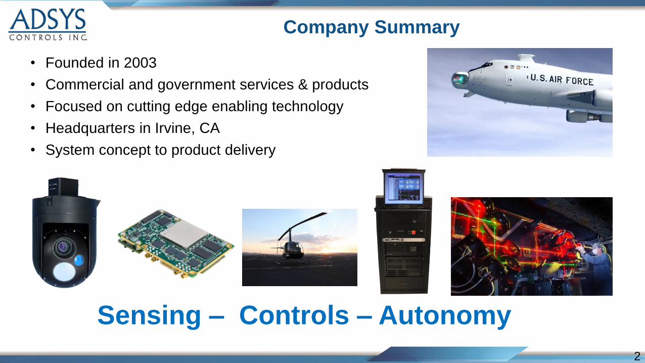
Company Summary
• Founded in 2003
• Commercial and government services & products
• Focused on cutting edge enabling technology
• Headquarters in Irvine, CA
• System concept to product delivery
Sensing – Controls – Autonomy
3
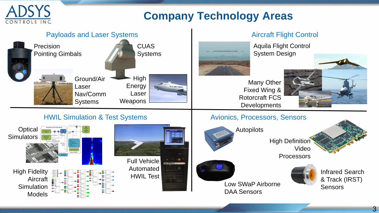
Company Technology Areas
Payloads and Laser Systems Aircraft Flight Control
HWIL Simulation & Test Systems Avionics, Processors, Sensors
CUAS
Systems
Precision
Pointing Gimbals
High
Energy
Laser
Weapons
Ground/Air
Laser
Nav/Comm
Systems
Autopilots
Full Vehicle
Automated
HWIL Test
21
Thermal_Out
20
Elec_Out
19
Fuel_Out
18
Payload_Out
17
Comm_Out
16
Altim_Out
15
AOAAOS_Out
14
AirData_Out
13
IRU_Out
12
NAV2_Out
11
NAV_Out
10
Net_Out
9
Launcher_Out
8
ACT_Out
7
EOM_Out
6
Envir_Out
5
Ground_Out
4
Control_Out
3
Mass_Out
2
Engine_Out
1
Aero_Out
EOM
Mass
Sim
uBlox_out
uBlox Navigator
Elec
Engine
Sim
Thermal_Out
Thermal Management
ACT
Sim
Env ir
control
Pilot Control
EOM
Sim
Pay load_Out
Payload
EOM
Mass
Sim
Nov Atel_out
Novatel OEMV-3 NavigatorEOM
Sim
Net_Out
Net Recovery
Engine
Control
Sim
Mass_Out
Mass Model
Sim
Aero
Engine
Mass
EOM
Launcher_Out
Launcher
EOM
Mass
IRU_out
IRU
[Net]
[Aero][Sim]
[Ground]
[Control]
[Envir]
[EOM]
[Therm]
[Elec]
[Mass]
[Payload]
[Comm]
[AirData]
[Altim]
[AOA_AOS]
[Fuel]
[IRU]
[NAV]
[NAV2]
[Launch]
[ACT]
[Engine]
Ground_Out
Gear Model
Env ir
Engine
Sim
Fuel_Out
Fuel System
[Engine]
[Therm]
[Elec]
[Sim]
[Engine]
[Aero]
[Elec]
[Fuel]
[Payload]
[Comm]
[Altim]
[AOA_AOS]
[AirData]
[IRU]
[Engine]
[Comm]
[Ground]
[Payload]
[Fuel]
[Sim]
[Engine]
[Envir]
[Sim]
[Sim]
[Sim]
[EOM]
[EOM]
[Sim]
[Sim]
[Sim]
[Sim]
[EOM]
[Envir]
[Sim]
[Envir]
[Control]
[EOM]
[Envir]
[ACT]
[Control]
[NAV2]
[Sim]
[Mass]
[EOM]
[Sim]
[NAV]
[Mass]
[EOM]
[Net]
[Sim]
[Sim]
[EOM]
[Launch][Launch]
[Mass]
[Engine]
[Envir]
[Mass]
[EOM]
[Envir]
[Sim]
[Ground]
[Control]
[Envir]
[EOM]
[Aero]
[Engine][Mass]
[Engine]
[Mass]
[EOM]
[ACT]
[EOM]
[Aero]
[Control]
[Engine]
[Envir]
[Sim]
[Aero]
[Sim]
[EOM]
[Mass]
[Sim]
Aero
Engine
Launch
Ground
Mass
Env ir
SimInit
EOM_Out
Equations of Motion
EOM
Sim
Env ir_out
Environmental Model
Control
Env ir
EOM
Sim
Engine_Out
Engine Model (fwB)
Engine
Comm
Pay load
Fuel
Sim
Elec_Out
Electrical Power1
EOM
Sim
Comm_Out
Comm System
EOM
Sim
Altimeter_Out
Altimeter
Env ir
Sim
Air_Data_out
Air Data
Env ir
Control
Engine
EOM
Mass
Aero_out
Aero Model (fwB)
Sim
hinge_mom
Actuators_Out
Actuators
Env ir
Sim
AOA_AOS_Out
AOA AOS
6
Engine Inputs
5
Nav Inputs
4
Envir Inputs
3
Discrete Events
2
Initial Conditions
1
Actuator Inputs
<sim_eng>
Sim
<sim_nav >
<sim_ev ents>
<sim_init>
<sim_act>
<sim_env ir>
High Fidelity
Aircraft
Simulation
Models
High Definition
Video
Processors
Aquila Flight Control
System Design
Many Other
Fixed Wing &
Rotorcraft FCS
Developments
Low SWaP Airborne
DAA Sensors
Optical
Simulators
Target Signature Model
Atmospheric Radiometric
Model
Background/Clutter-clear sky-clouds-terra in
RadianceDue to atmosphereAnd background
Transmittance
RadianceNoise:
-Shot noise-readout noise-fixed pattern noise-NEP-Dark Current
contrast signal
+
Camera Model
To Sensor Processing
MTF blur
CN2 Turbulence
SNRassociated
with
Synthetic Scene
÷
+fx
Mathematical Operation
Models
Optics Radiance
Applied to whole image
Atmospheric and Target Model
Input Model Parameters
Infrared Search
& Track (IRST)
Sensors
4
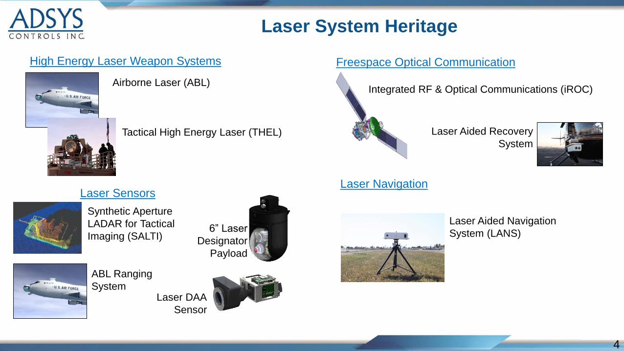
Laser System Heritage
High Energy Laser Weapon Systems Freespace Optical Communication
Laser SensorsLaser Navigation
Airborne Laser (ABL)
Tactical High Energy Laser (THEL)
Synthetic Aperture
LADAR for Tactical
Imaging (SALTI)
Integrated RF & Optical Communications (iROC)
Laser Aided Navigation
System (LANS)
Laser Aided Recovery
System
ABL Ranging
System
6” Laser
Designator
Payload
Laser DAA
Sensor
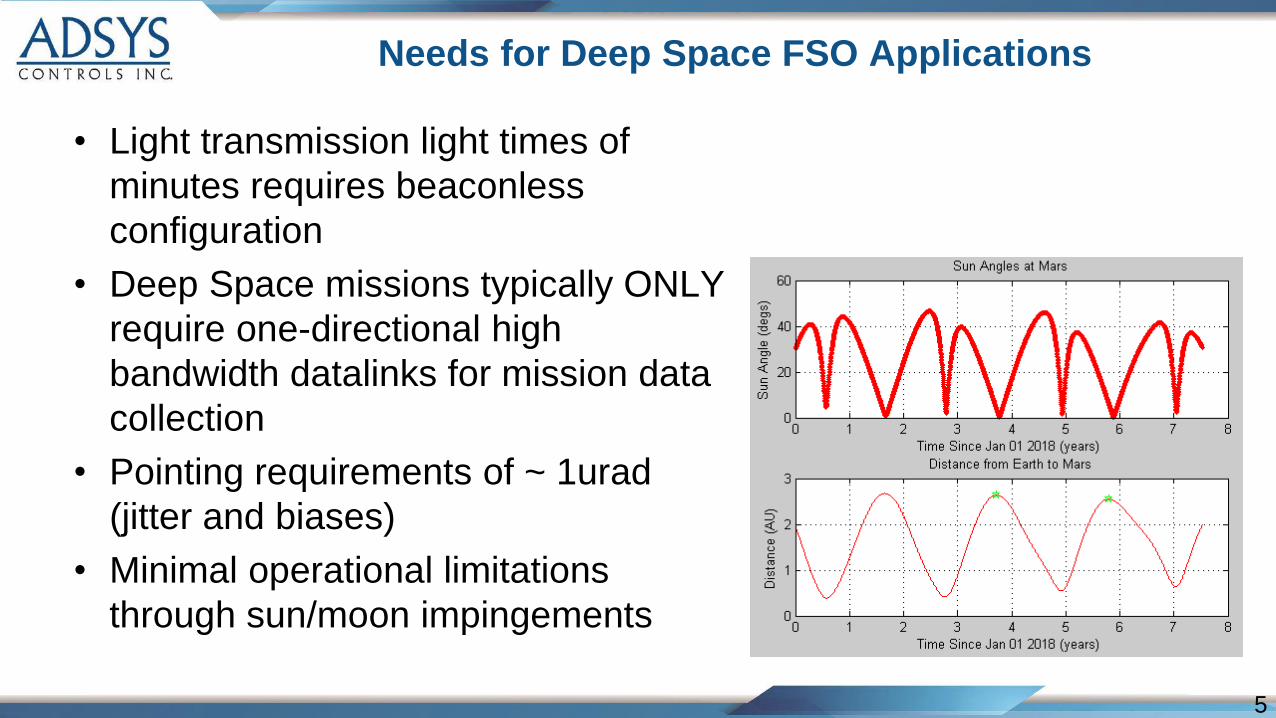
• Light transmission light times of
minutes requires beaconless
configuration
• Deep Space missions typically ONLY
require one-directional high
bandwidth datalinks for mission data
collection
• Pointing requirements of ~ 1urad
(jitter and biases)
• Minimal operational limitations
through sun/moon impingements
5
Needs for Deep Space FSO Applications
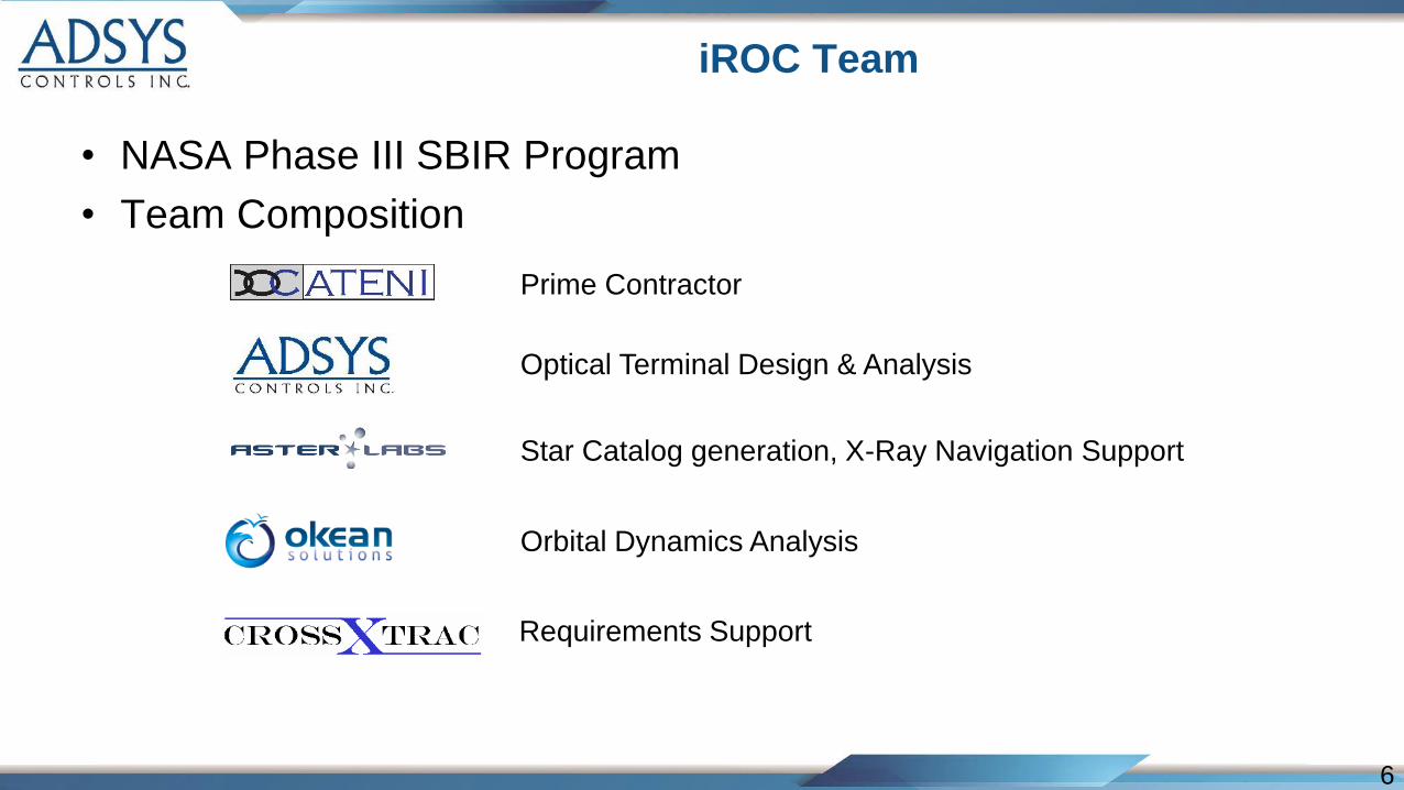
• NASA Phase III SBIR Program
• Team Composition
6
iROC Team
Prime Contractor
Optical Terminal Design & Analysis
Star Catalog generation, X-Ray Navigation Support
Orbital Dynamics Analysis
Requirements Support
7
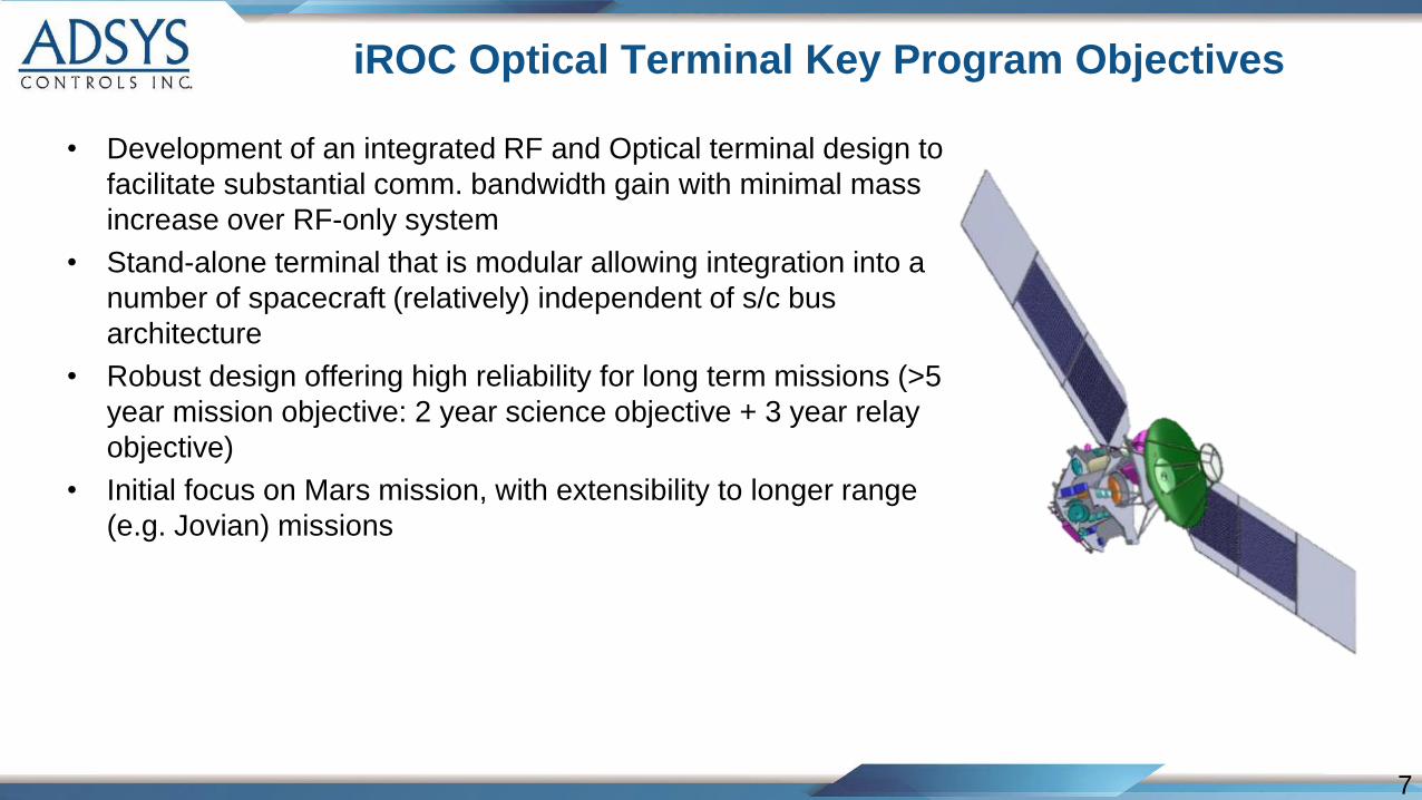
iROC Optical Terminal Key Program Objectives
• Development of an integrated RF and Optical terminal design to
facilitate substantial comm. bandwidth gain with minimal mass
increase over RF-only system
• Stand-alone terminal that is modular allowing integration into a
number of spacecraft (relatively) independent of s/c bus
architecture
• Robust design offering high reliability for long term missions (>5
year mission objective: 2 year science objective + 3 year relay
objective)
• Initial focus on Mars mission, with extensibility to longer range
(e.g. Jovian) missions
8
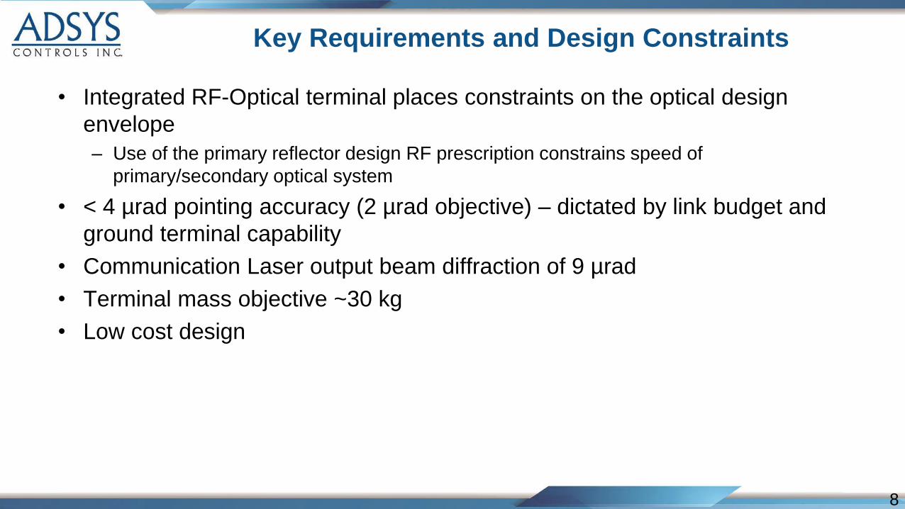
Key Requirements and Design Constraints
• Integrated RF-Optical terminal places constraints on the optical design
envelope
– Use of the primary reflector design RF prescription constrains speed of
primary/secondary optical system
• < 4 µrad pointing accuracy (2 µrad objective) – dictated by link budget and
ground terminal capability
• Communication Laser output beam diffraction of 9 µrad
• Terminal mass objective ~30 kg
• Low cost design
9
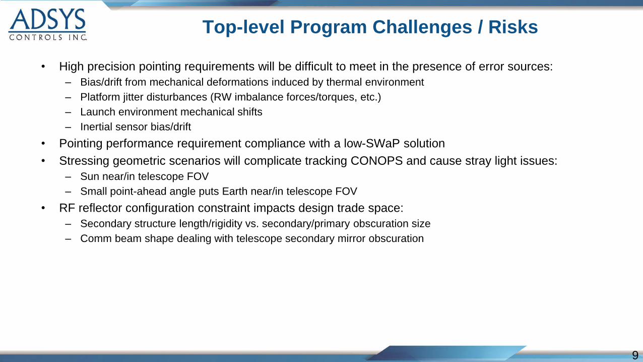
Top-level Program Challenges / Risks
• High precision pointing requirements will be difficult to meet in the presence of error sources:
– Bias/drift from mechanical deformations induced by thermal environment
– Platform jitter disturbances (RW imbalance forces/torques, etc.)
– Launch environment mechanical shifts
– Inertial sensor bias/drift
• Pointing performance requirement compliance with a low-SWaP solution
• Stressing geometric scenarios will complicate tracking CONOPS and cause stray light issues:
– Sun near/in telescope FOV
– Small point-ahead angle puts Earth near/in telescope FOV
• RF reflector configuration constraint impacts design trade space:
– Secondary structure length/rigidity vs. secondary/primary obscuration size
– Comm beam shape dealing with telescope secondary mirror obscuration
10
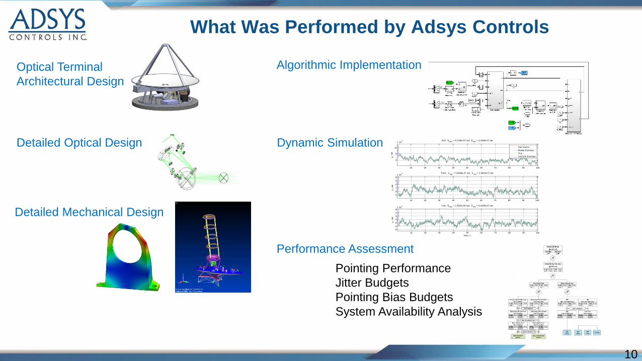
What Was Performed by Adsys Controls
Optical Terminal
Architectural Design
Detailed Optical Design
Detailed Mechanical Design
Algorithmic Implementation
Dynamic Simulation
Performance Assessment
-400
-300
-200
-100
0
100
-300
-200
-100
0
100
200
300
400
500
-1500
-1000
-500 0
500
1000
1500
2000
2500
mm
mm
10 20 30 40 50 60 70 80 90 100
0
5
10
x 10-4 Roll, E
max = 8.1769e-07 rad, E
rms = 2.3338e-07 rad
,
rad
Star tracker
Matlab Estimate
True
Simulink Estimate
10 20 30 40 50 60 70 80 90 100
-2
0
2
4
6
8
x 10-4 Pitch, E
max = 9.9958e-07 rad, E
rms = 2.6663e-07 rad
,
rad
10 20 30 40 50 60 70 80 90 100
-4
-2
0
2
4
6
8x 10
-4 Yaw, Emax
= 1.5915e-06 rad, Erms
= 6.1835e-07 rad
,
rad
Time, s
Pointing Performance
Jitter Budgets
Pointing Bias Budgets
System Availability Analysis
11
Beaconless FSO Design Summary
• Innovative optical design performed
• Algorithm design for PAT/jitter control retired significant risks
• Validated required performance via high fidelity simulation
Summary
• Beaconless pointing via celestial referencing
• Incorporated low-SWaP-C star trackers on optical platform
• Efficient optical design
• Robust operations through Moon/Sun interference cases
Key Design Aspects