Embed Size (px)
Citation preview

Issue 01/2006 Art. No. 7001-0026
Operating Manual
APT.line® BD (E2)
Incubators with natural convection
APT.line® ED (E2)
Heating/drying ovens with natural convection
APT.line® FD (E2)
Heating/drying ovens with forced convection
with R3 Controller BINDER GmbH Address Post office box 102 D-78502 Tuttlingen Tel. +49 7462 2005 0 Fax +49 7462 2005 93 0 Internet http://www.binder-world.com E-mail [email protected] Service Hotline +49 7462 2005 555 Service Fax +49 7462 2005 93 555 Service E-Mail [email protected] Service Hotline USA +1 866 816 8191 Service Hotline Asia Pacific +603 6204 2855
BD / ED / FD 01/2006 page 2/49
EG - KONFORMITÄTSERKLÄRUNG EC - DECLARATION OF CONFORMITY CE - DECLARATION DE CONFORMITE
Anbieter / Supplier / Fournisseur: BINDER GmbH Anschrift / Address / Adresse : Im Mittleren Ösch 5, D-78532 Tuttlingen Produkt / Product / Produit: Brutschränke mit natürlicher Umluft
Incubators with natural convection Incubateurs à circulation d’air naturelle
Typenbezeichnung / Type / Type BD 23, BD 53, BD 115, BD 240, BD 400, BD 720 Die oben beschriebenen Produkte sind konform mit folgenden harmonisierten Normen: The products described above are in conformity with the following harmonized standards: Les produits décrits ci-dessus sont conformes aux normes harmonisées suivantes: Sicherheit / safety / sécurité: IEC/CEI 61010-1:2001 Sicherheitsbestimmungen für elektrische Mess-, Steuer-, Regel-
und Laborgeräte – Teil 1: Allgemeine Anforderungen Safety requirements for electrical equipment for measurement, control, and laboratory use – Part 1: General requirements Règles de sécurité pour appareils électriques de mesurage, de régulation et de laboratoire – Partie 1 : Prescriptions générales
IEC/CEI 61010-2-010:2003 Sicherheitsbestimmungen für elektrische Meß-, Steuer-, Regel- und Laborgeräte – Teil 2-010: Besondere Anforderungen an Laborgeräte für das Erhitzen von Stoffen Safety requirements for electrical equipment for measurement, control, and laboratory use – Part 2-010: Particular requirements for laboratory equipment for the heating of materials Règles de sécurité pour appareils électriques de mesurage, de régulation et de laboratoire. Partie 2-010 : Prescriptions particulières pour appareils de laboratoire utilisés pour l’échauffement des matières
EMV / EMC / CEM: IEC/CEI 61326:1997 + A1:1998 + A2:2000
Elektrische Betriebsmittel für Leittechnik und Laboreinsatz – EMV-Anforderungen Electrical equipment for measurement, control and laboratory use – EMC requirements Matériels électriques de mesure, de commande et de laboratoire – Prescriptions relatives à la CEM
1 / 2
BD / ED / FD 01/2006 page 3/49
Die oben beschriebenen Produkte sind konform mit folgenden EG-Richtlinien: The products described above are in conformity with the following EC guidelines: Les produits décrits ci-dessus sont conformes aux directives CE suivantes: Niederspannungsrichtlinie 73/23/EWG, Änderung 93/68/EWG Low voltage directive 73/23/EEC, amended 93/68/EEC Directive basse tension 73/23/CEE, modifiée 93/68/CEE
Richtlinie 73/23/EWG des Rates vom 19. Februar 1973 zur Angleichung der Rechtsvorschriften der Mitgliedstaaten betreffend elektrische Betriebsmittel zur Verwendung innerhalb bestimmter Spannungsgrenzen Council Directive of 19 February 1973 on the harmonization of the laws of Member States relating to electrical equipment designed for use within certain voltage limits (73/23/EEC) Directive 73/23/CEE du Conseil, du 19 février 1973, concernant le rapprochement des législations des États membres relatives au matériel électrique destiné à être employé dans certaines limites de tension
EMV-Richtlinie 89/336/EWG, Änderung 93/68/EWG EMC Directive 89/336/EEC, amended 93/68/EEC Directive CEM 89/336/CEE, modifiée 93/68/CEE
Richtlinie 89/336/EWG des Rates vom 3. Mai 1989 zur Angleichung der Rechtsvorschriften der Mitgliedstaaten über die elektromagnetische Verträglichkeit Council Directive 89/336/EEC of 3 May 1989 on the approximation of the laws of the Member States relating to electromagnetic compatibility Directive 89/336/CEE du Conseil du 3 mai 1989 concernant le rapprochement des législations des États membres relatives à la compatibilité électromagnétique
Die oben beschriebenen Produkte tragen entsprechend die Kennzeichnung CE. The products described above, corresponding to this, bear the CE-mark Les produits décrits ci-dessus, en correspondance, portent l’indication CE. D-78532 Tuttlingen, 10.01.2006 BINDER GmbH
P. M. Binder Dr.-Ing. V. Kek Geschäftsführender Gesellschafter Leiter F & E Managing Director Head of R & D Directeur général Chef de service R&D
2 / 2
BD / ED / FD 01/2006 page 4/49
EG - KONFORMITÄTSERKLÄRUNG EC - DECLARATION OF CONFORMITY CE - DECLARATION DE CONFORMITE
Anbieter / Supplier / Fournisseur: BINDER GmbH Anschrift / Address / Adresse : Im Mittleren Ösch 5, D-78532 Tuttlingen Produkt / Product / Produit: Wärme-/Trockenschränke mit natürlicher Umluft
Heating/drying ovens with natural convection Etuves universelles à circulation d’air naturelle
Typenbezeichnung / Type / Type ED 23, ED 53, ED 115, ED 240, ED 400, ED 720 Die oben beschriebenen Produkte sind konform mit folgenden harmonisierten Normen: The products described above are in conformity with the following harmonized standards: Les produits décrits ci-dessus sont conformes aux normes harmonisées suivantes: Sicherheit / safety / sécurité: IEC/CEI 61010-1:2001 Sicherheitsbestimmungen für elektrische Mess-, Steuer-, Regel-
und Laborgeräte – Teil 1: Allgemeine Anforderungen Safety requirements for electrical equipment for measurement, control, and laboratory use – Part 1: General requirements Règles de sécurité pour appareils électriques de mesurage, de régulation et de laboratoire – Partie 1 : Prescriptions générales
IEC/CEI 61010-2-010:2003 Sicherheitsbestimmungen für elektrische Meß-, Steuer-, Regel- und Laborgeräte – Teil 2-010: Besondere Anforderungen an Laborgeräte für das Erhitzen von Stoffen Safety requirements for electrical equipment for measurement, control, and laboratory use – Part 2-010: Particular requirements for laboratory equipment for the heating of materials Règles de sécurité pour appareils électriques de mesurage, de régulation et de laboratoire. Partie 2-010 : Prescriptions particulières pour appareils de laboratoire utilisés pour l’échauffement des matières
EMV / EMC / CEM: IEC/CEI 61326:1997 + A1:1998 + A2:2000
Elektrische Betriebsmittel für Leittechnik und Laboreinsatz – EMV-Anforderungen Electrical equipment for measurement, control and laboratory use – EMC requirements Matériels électriques de mesure, de commande et de laboratoire – Prescriptions relatives à la CEM
1 / 2
BD / ED / FD 01/2006 page 5/49
Die oben beschriebenen Produkte sind konform mit folgenden EG-Richtlinien: The products described above are in conformity with the following EC guidelines: Les produits décrits ci-dessus sont conformes aux directives CE suivantes: Niederspannungsrichtlinie 73/23/EWG, Änderung 93/68/EWG Low voltage directive 73/23/EEC, amended 93/68/EEC Directive basse tension 73/23/CEE, modifiée 93/68/CEE
Richtlinie 73/23/EWG des Rates vom 19. Februar 1973 zur Angleichung der Rechtsvorschriften der Mitgliedstaaten betreffend elektrische Betriebsmittel zur Verwendung innerhalb bestimmter Spannungsgrenzen Council Directive of 19 February 1973 on the harmonization of the laws of Member States relating to electrical equipment designed for use within certain voltage limits (73/23/EEC) Directive 73/23/CEE du Conseil, du 19 février 1973, concernant le rapprochement des législations des États membres relatives au matériel électrique destiné à être employé dans certaines limites de tension
EMV-Richtlinie 89/336/EWG, Änderung 93/68/EWG EMC Directive 89/336/EEC, amended 93/68/EEC Directive CEM 89/336/CEE, modifiée 93/68/CEE
Richtlinie 89/336/EWG des Rates vom 3. Mai 1989 zur Angleichung der Rechtsvorschriften der Mitgliedstaaten über die elektromagnetische Verträglichkeit Council Directive 89/336/EEC of 3 May 1989 on the approximation of the laws of the Member States relating to electromagnetic compatibility Directive 89/336/CEE du Conseil du 3 mai 1989 concernant le rapprochement des législations des États membres relatives à la compatibilité électromagnétique
Die oben beschriebenen Produkte tragen entsprechend die Kennzeichnung CE. The products described above, corresponding to this, bear the CE-mark Les produits décrits ci-dessus, en correspondance, portent l’indication CE. D-78532 Tuttlingen, 10.01.2006 BINDER GmbH
P. M. Binder Dr.-Ing. V. Kek Geschäftsführender Gesellschafter Leiter F & E Managing Director Head of R & D Directeur général Chef de service R&D
2 / 2

BD / ED / FD 01/2006 page 6/49
EG - KONFORMITÄTSERKLÄRUNG EC - DECLARATION OF CONFORMITY CE - DECLARATION DE CONFORMITE
Anbieter / Supplier / Fournisseur: BINDER GmbH Anschrift / Address / Adresse : Im Mittleren Ösch 5, D-78532 Tuttlingen Produkt / Product / Produit: Wärme-/Trockenschränke mit forcierter Umluft
Heating/drying ovens with forced convection Etuves universelles à circulation d’air forcée
Typenbezeichnung / Type / Type FD 23, FD 53, FD 115, FD 240 Die oben beschriebenen Produkte sind konform mit folgenden harmonisierten Normen: The products described above are in conformity with the following harmonized standards: Les produits décrits ci-dessus sont conformes aux normes harmonisées suivantes: Sicherheit / safety / sécurité: IEC/CEI 61010-1:2001 Sicherheitsbestimmungen für elektrische Mess-, Steuer-, Regel-
und Laborgeräte – Teil 1: Allgemeine Anforderungen Safety requirements for electrical equipment for measurement, control, and laboratory use – Part 1: General requirements Règles de sécurité pour appareils électriques de mesurage, de régulation et de laboratoire – Partie 1 : Prescriptions générales
IEC/CEI 61010-2-010:2003 Sicherheitsbestimmungen für elektrische Meß-, Steuer-, Regel- und Laborgeräte – Teil 2-010: Besondere Anforderungen an Laborgeräte für das Erhitzen von Stoffen Safety requirements for electrical equipment for measurement, control, and laboratory use – Part 2-010: Particular requirements for laboratory equipment for the heating of materials Règles de sécurité pour appareils électriques de mesurage, de régulation et de laboratoire. Partie 2-010 : Prescriptions particulières pour appareils de laboratoire utilisés pour l’échauffement des matières
EMV / EMC / CEM: IEC/CEI 61326:1997 + A1:1998 + A2:2000
Elektrische Betriebsmittel für Leittechnik und Laboreinsatz – EMV-Anforderungen Electrical equipment for measurement, control and laboratory use – EMC requirements Matériels électriques de mesure, de commande et de laboratoire – Prescriptions relatives à la CEM
1 / 2

BD / ED / FD 01/2006 page 7/49
Die oben beschriebenen Produkte sind konform mit folgenden EG-Richtlinien: The products described above are in conformity with the following EC guidelines: Les produits décrits ci-dessus sont conformes aux directives CE suivantes: Niederspannungsrichtlinie 73/23/EWG, Änderung 93/68/EWG Low voltage directive 73/23/EEC, amended 93/68/EEC Directive basse tension 73/23/CEE, modifiée 93/68/CEE
Richtlinie 73/23/EWG des Rates vom 19. Februar 1973 zur Angleichung der Rechtsvorschriften der Mitgliedstaaten betreffend elektrische Betriebsmittel zur Verwendung innerhalb bestimmter Spannungsgrenzen Council Directive of 19 February 1973 on the harmonization of the laws of Member States relating to electrical equipment designed for use within certain voltage limits (73/23/EEC) Directive 73/23/CEE du Conseil, du 19 février 1973, concernant le rapprochement des législations des États membres relatives au matériel électrique destiné à être employé dans certaines limites de tension
EMV-Richtlinie 89/336/EWG, Änderung 93/68/EWG EMC Directive 89/336/EEC, amended 93/68/EEC Directive CEM 89/336/CEE, modifiée 93/68/CEE
Richtlinie 89/336/EWG des Rates vom 3. Mai 1989 zur Angleichung der Rechtsvorschriften der Mitgliedstaaten über die elektromagnetische Verträglichkeit Council Directive 89/336/EEC of 3 May 1989 on the approximation of the laws of the Member States relating to electromagnetic compatibility Directive 89/336/CEE du Conseil du 3 mai 1989 concernant le rapprochement des législations des États membres relatives à la compatibilité électromagnétique
Die oben beschriebenen Produkte tragen entsprechend die Kennzeichnung CE. The products described above, corresponding to this, bear the CE-mark Les produits décrits ci-dessus, en correspondance, portent l’indication CE. D-78532 Tuttlingen, 10.01.2006 BINDER GmbH
P. M. Binder Dr.-Ing. V. Kek Geschäftsführender Gesellschafter Leiter F & E Managing Director Head of R & D Directeur général Chef de service R&D
2 / 2
BD / ED / FD 01/2006 page 8/49
Content
1. SAFETY................................................................................................................ 10 1.1 Legal considerations .........................................................................................................................10 1.2 Structure of the safety instructions....................................................................................................10 1.3 Localization / position of safety labels at the unit..............................................................................12 1.4 Type plate .........................................................................................................................................13 1.5 General safety instructions on installing and operating the incubators BD and heating/drying ovens
ED and FD ........................................................................................................................................13 1.6 Intended use .....................................................................................................................................15
1.6.1 Incubators BD..........................................................................................................................15 1.6.2 Heating/drying ovens ED and FD............................................................................................15
2. WARRANTY......................................................................................................... 15
3. UNIT DESCRIPTION ............................................................................................ 17 3.1 Equipment overview BD/ED/FD........................................................................................................17
4. SCOPE OF DELIVERY, TRANSPORTATION, STORAGE, AND INSTALLATION18 4.1 Unpacking, and checking equipment and scope of delivery.............................................................18 4.2 Advice for safe lifting and transportation...........................................................................................18 4.3 Storage..............................................................................................................................................19 4.4 Location of installation and ambient conditions ................................................................................19
5. INSTALLATION OF THE EQUIPMENT ............................................................... 20 5.1 Electrical connection .........................................................................................................................20 5.2 Connection to a suction plant (optional) ...........................................................................................20
6. START UP............................................................................................................ 21 6.1 Switching on the unit .........................................................................................................................21 6.2 Heating operation display .................................................................................................................21 6.3 Air change .........................................................................................................................................21
7. CONTROLLER SETTING..................................................................................... 22 7.1 Display / entry of temperature set-point (without ramp function) ......................................................22 7.2 Display / entry of temperature set-point (with selected temperature ramp)......................................22 7.3 Time functions: Continuous operation and Timer operation.............................................................23
7.3.1 Switching between Continuous operation and Timer operation .............................................24 7.3.2 Continuous operation ..............................................................................................................24 7.3.3 Timer operation: Setting the tempering time ...........................................................................25
7.4 User level settings.............................................................................................................................26 7.4.1 Temperature unit change between degrees Celsius °C and degrees Fahrenheit °F .............26 7.4.2 Enter a temperature ramp .......................................................................................................27 7.4.3 Chamber addressing ...............................................................................................................27
7.5 General notes....................................................................................................................................28
8. SAFETY DEVICES ............................................................................................... 29 8.1 Temperature safety device class 2 (DIN 12880) ED, FD .................................................................29 8.2 Temperature safety device class 3.1 (DIN 12880) BD (option ED, FD))..........................................30
9. OPTIONS.............................................................................................................. 31 9.1 Disconnectable acoustic over-temperature alarm (option) ...............................................................31 9.2 Communication software APT-COM® 3 DataControlSystem (BD, option ED) .................................32 9.3 Analog output for temperature (option).............................................................................................32 9.4 Additional Pt100 temperature sensor (option BD) ............................................................................32 9.5 Water protected internal socket (option BD).....................................................................................33
BD / ED / FD 01/2006 page 9/49
10. MAINTENANCE, CLEANING, AND SERVICE .................................................... 33 10.1 Maintenance intervals, service..........................................................................................................33 10.2 Cleaning and decontamination .........................................................................................................34
11. DISPOSAL............................................................................................................ 35 11.1 Disposal of the transport packing .....................................................................................................35 11.2 Decommissioning..............................................................................................................................36 11.3 Disposal of the unit............................................................................................................................36
12. TECHNICAL DESCRIPTION................................................................................ 36 12.1 Factory calibration and adjustment ...................................................................................................36 12.2 Definition of usable space.................................................................................................................36 12.3 Over current protection .....................................................................................................................37 12.4 Technical data series BD ..................................................................................................................37 12.5 Technical data series ED ..................................................................................................................39 12.6 Technical data series FD ..................................................................................................................40 12.7 Equipment and Options Series BD ...................................................................................................42 12.8 Equipment and Options Series ED ...................................................................................................43 12.9 Equipment and Options Series FD ...................................................................................................44 12.10 Spare parts........................................................................................................................................45
13. CONTAMINATION CLEARANCE CERTIFICATE ............................................... 47
BD / ED / FD 01/2006 page 10/49
Dear customer, For the proper operation of the incubators BD and heating/drying ovens ED and FD, it is necessary to read this operating manual completely and carefully and to observe the given instructions.
1. Safety
This operating manual is part of the scope of delivery. Always keep it at hand.
To avoid injuries and damage observe the safety instructions of the operating manual.
WARNING
Failure to observe the safety instructions.
Serious injuries and unit damage.
Observe the safety instructions in this operating manual
Carefully read the complete operating instructions of the incubators BD and heating/drying ovens ED and FD
1.1 Legal considerations
This operating manual contains information necessary for the intended use, correct installation, start-up and operation, and for the maintenance of the unit.
Understanding and observing the instructions in this operating manual are prerequisites for hazard-free use and safety during operation and maintenance.
This operating manual cannot cover all conceivable applications. If you would like additional information, or if special problems arise that you feel are not sufficiently addressed in this manual, please ask your dealer or contact us directly.
Furthermore, we note that the contents of this operating manual are not part of an earlier or existing agreement, promise, or legal relationship, nor do they modify such a relationship. All obligations on the part of BINDER derive from the respective purchase contract, which also contains the entire and exclusively valid statement of warranty administration. The statements in this manual neither augment nor restrict the contractual warranty provisions.
1.2 Structure of the safety instructions
In this operating manual, the following harmonized denominations and symbols indicate dangerous situations following the harmonization of ISO 3864-2 and ANSI Z535.4.
Signal word panel Depending on seriousness and probability of the consequences, dangers are identified with a signal word, the corresponding safety color, and if appropriate, the safety alert symbol.
DANGER
Indicates an imminently hazardous situation that, if not avoided, will result in death or serious (irreversible) injury.
WARNING
Indicates a potentially hazardous situation which, if not avoided, could result in death or serious (irreversible) injury

BD / ED / FD 01/2006 page 11/49
CAUTION
Indicates a potentially hazardous situation which, if not avoided, may result in moderate or minor (reversible) injury
CAUTION Indicates a potentially hazardous situation which, if not avoided, may result in damage of the product and/or its functions or of a property in its ambiance. Safety alert symbol
Use of the safety alert symbol indicates risk of injury. Observe all measures that are marked with the safety alert symbol in order to avoid death or injury.
Pictograms
Warning signs
Electrical hazard
Explosive substances
Hot surface
Pollution Hazard
Tipover hazard
Mandatory action signs
Mandatory regulation
Lift with several persons
Read operating instructions
Lift with mechanical assistance
Pull the power plug
Environment protection
Prohibition signs
Do NOT touch
Do NOT spray with water
BD / ED / FD 01/2006 page 12/49
Information to be observed in order to ensure optimum function of the product.
Word message panel structure
Type / cause of hazard.
Possible consequences.
∅ Instruction how to avoid the hazard: prohibition
Instruction how to avoid the hazard: mandatory action Observe the other notes and information not specially emphasized in the same way, in order to avoid disturbances which could result in direct or indirect injuries or property damage.
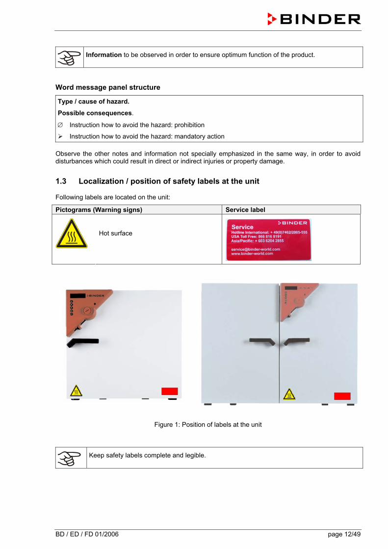
1.3 Localization / position of safety labels at the unit
Following labels are located on the unit:
Pictograms (Warning signs) Service label
Hot surface
Figure 1: Position of labels at the unit
Keep safety labels complete and legible.

BD / ED / FD 01/2006 page 13/49
1.4 Type plate
Figure 2: Type plate (example: FD 115 regular unit)
Indications of the type plate Information Nenntemperatur 300°C
572°F Nominal temperature
Schutzart IP 20 IP type of protection 20 acc. to EN 60529 Temp. Schutz DIN 12880 Temperature safety device acc. to standard DIN 12880 Klasse 2.0 Temperature safety device, class 2 Artikel-Nr. 9010-0102 Art. No. 9010-0102 Projekt-Nr. --- (Special application acc. to project no.) 1,60 kW Nominal power 1.60 kW 230 V 1 N ~ Nominal voltage 230 V ± 10%, single-phase unit 7,0 A Nominal current 7.0 A 50/60 Hz Mains supply 50/60 Hz FD 115 Model FD 115 # 00-00000 Serial No. 00-00000
1.5 General safety instructions on installing and operating the incubators BD and heating/drying ovens ED and FD
With regard to operating the incubators BD and heating/drying ovens ED and FD and to the installation location, please observe the regulations BGR 120 of the German professional association of the chemical industry (formerly ZH 1/119 laboratory guidelines of the employers’ liability insurance association) (for Germany).
The BINDER GmbH is responsible for safety-related unit properties only if skilled electricians or qualified personnel authorized by BINDER perform all maintenance and repair, and if components relating to chamber safety are replaced in case of failure with original spare parts.
To operate the unit, use only original BINDER accessories or accessories of third-party suppliers authorized by BINDER. The user is responsible for any risk when using unauthorized accessories.
CAUTION
Danger of overheating.
Damage of the unit.
∅ Do not install the unit in unventilated recesses.
Ensure sufficient ventilation for carrying-off the heat.
Nenntemperatur 300°C 1,60 kW
572°F 230 V 1 N ~ Schutzart IP 20 7,0 A Temp. Schutz DIN 12880 50/60 Hz Klasse 2.0 Artikel-Nr. 9010-0102 US PATS 5405194 / 5222612 Projekt-Nr. US PATS 4585923 / 5309981
D 78532 Tuttlingen / GermanyTel. + 49 (0) 7462 / 2005-0Internet: www.binder-world.com
FD 115 # 00-00000 Made in Germany

BD / ED / FD 01/2006 page 14/49
The incubators BD and heating/drying ovens ED and FD must NOT be operated in hazardous locations.
DANGER
Explosion hazard. Danger of life.
∅ Do NOT operate the unit in potentially explosive areas.
∅ NO explosive dust or air-solvent mixture in the ambiance.
The incubators BD and heating/drying ovens ED and FD do not dispose of any measures of explosion protection.
DANGER
Explosion hazard. Danger of life.
∅ Do NOT introduce any substance combustible or explosive at working temperature into the heating/drying oven.
∅ NO explosive dust or air-solvent mixture in the inner chamber.
Any solvent contained in the charging material must not be explosive or inflammable. I.e., irrespective of the solvent concentration in the steam room, NO explosive mixture with air will form. The temperature inside the chamber must lie below the flash point or below the sublimation point of the charging material. Keep informed about the physical and chemical properties of the charging material, as well as the contained moisture constituent and its behavior under addition of heat energy.
Keep informed about any potential health risks caused by the charging material, the contained moisture constituent or by reaction products that may arise during the temperature process. Take adequate measures to exclude such risks prior to putting the multifunctional heating/drying oven into operation.
DANGER
Electrical hazard.
Danger of life. ∅ The unit must NOT become wet during operation or maintenance.
The multifunctional heating/drying ovens have been produced in accordance to the VDE regulations and were routinely tested in accordance to VDE 0411.
CAUTION
The inner chamber, the outgoing air pipe, and the door window (option) will become hot during operation. Danger of burning.
∅ Do NOT touch the inner surfaces, the door window, the access ports, and the charging material during operation.
BD / ED / FD 01/2006 page 15/49
1.6 Intended use
1.6.1 Incubators BD
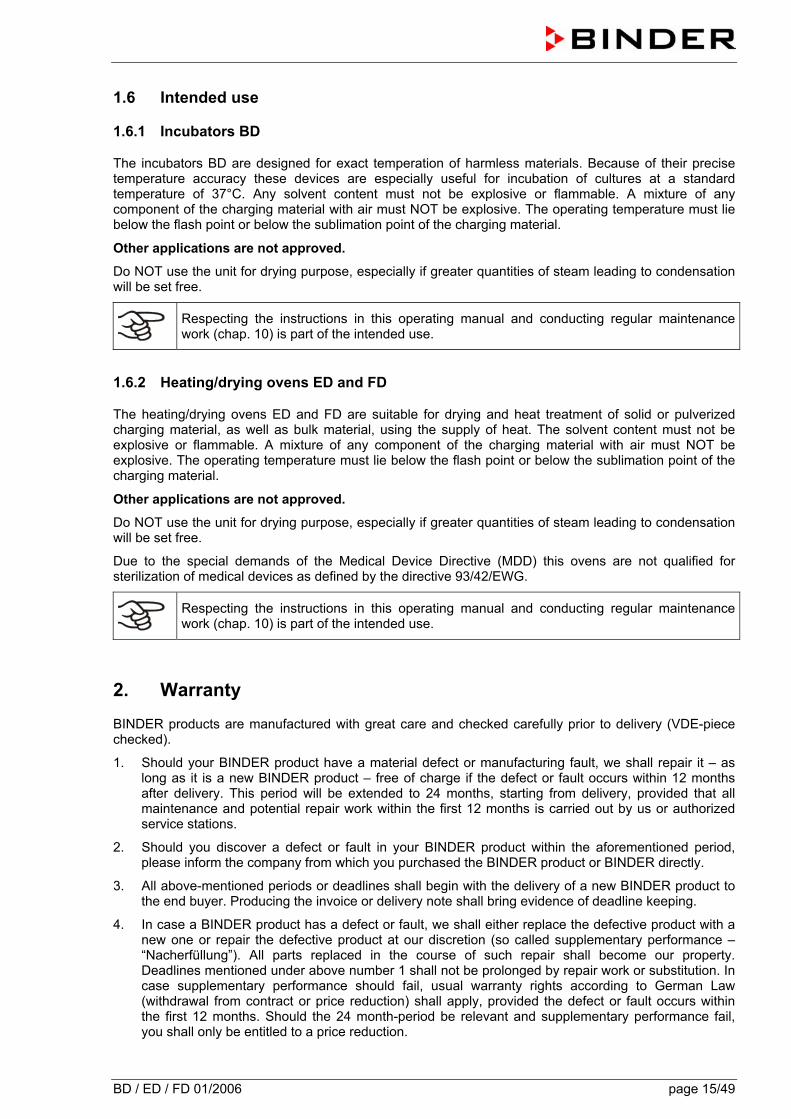
The incubators BD are designed for exact temperation of harmless materials. Because of their precise temperature accuracy these devices are especially useful for incubation of cultures at a standard temperature of 37°C. Any solvent content must not be explosive or flammable. A mixture of any component of the charging material with air must NOT be explosive. The operating temperature must lie below the flash point or below the sublimation point of the charging material.
Other applications are not approved.
Do NOT use the unit for drying purpose, especially if greater quantities of steam leading to condensation will be set free.
Respecting the instructions in this operating manual and conducting regular maintenance work (chap. 10) is part of the intended use.
1.6.2 Heating/drying ovens ED and FD
The heating/drying ovens ED and FD are suitable for drying and heat treatment of solid or pulverized charging material, as well as bulk material, using the supply of heat. The solvent content must not be explosive or flammable. A mixture of any component of the charging material with air must NOT be explosive. The operating temperature must lie below the flash point or below the sublimation point of the charging material.
Other applications are not approved.
Do NOT use the unit for drying purpose, especially if greater quantities of steam leading to condensation will be set free.
Due to the special demands of the Medical Device Directive (MDD) this ovens are not qualified for sterilization of medical devices as defined by the directive 93/42/EWG.
Respecting the instructions in this operating manual and conducting regular maintenance work (chap. 10) is part of the intended use.
2. Warranty
BINDER products are manufactured with great care and checked carefully prior to delivery (VDE-piece checked).
1. Should your BINDER product have a material defect or manufacturing fault, we shall repair it – as long as it is a new BINDER product – free of charge if the defect or fault occurs within 12 months after delivery. This period will be extended to 24 months, starting from delivery, provided that all maintenance and potential repair work within the first 12 months is carried out by us or authorized service stations.
2. Should you discover a defect or fault in your BINDER product within the aforementioned period, please inform the company from which you purchased the BINDER product or BINDER directly.
3. All above-mentioned periods or deadlines shall begin with the delivery of a new BINDER product to the end buyer. Producing the invoice or delivery note shall bring evidence of deadline keeping.
4. In case a BINDER product has a defect or fault, we shall either replace the defective product with a new one or repair the defective product at our discretion (so called supplementary performance – “Nacherfüllung”). All parts replaced in the course of such repair shall become our property. Deadlines mentioned under above number 1 shall not be prolonged by repair work or substitution. In case supplementary performance should fail, usual warranty rights according to German Law (withdrawal from contract or price reduction) shall apply, provided the defect or fault occurs within the first 12 months. Should the 24 month-period be relevant and supplementary performance fail, you shall only be entitled to a price reduction.
BD / ED / FD 01/2006 page 16/49
5. Should the defect occur within 12 months after delivery, we shall take over all costs necessary for
the repair of the defect, especially transportation, travel and labor costs, in so far as there is no cost increase due to the product being brought to another location than the place of delivery. However, we shall decide whether the defect will be repaired at the location where the BINDER product is operating or whether the BINDER product has to be sent to us. In case the 24 month-period should be relevant, please send the defective BINDER product at your expense to BINDER or the company from which you purchased the BINDER product. We shall repair the BINDER product at your premises only if transportation costs are excessively high. The customer shall be liable for any risk of sudden destruction or deterioration.
6. Should you have to send back a BINDER product, the BINDER product will have to be supplied in its original packaging or any similar suitable packaging.
7. All warranty claims as laid down in this document basically become invalid:
− if the defect or fault is caused by repair or intervention by non-authorized persons. With authorized persons, we mean only Binder service engineers and service engineers of our service partners.
− the same applies if you have attached non-suitable parts or accessories to the BINDER products, which are not original BINDER spare parts, and if those parts or accessories have caused the defect or fault.
− parts that become used due to natural wear and tear, e.g. door seals, lamps, lights (enumeration not exhaustive)
− defects caused by external intervention like e.g. fall or blow
− defects arising from non-compliance with operating instructions, improper use, abnormal ambient conditions, overload or absence of care/maintenance
− in the case of devices that were converted or redesigned by non-authorized third parties
− in case of minor deviations from the set quality that are irrelevant to the value and usability of the device
8. All rights or claims beyond the ones described above, especially concerning the right of compensation for potential damages which might be caused by BINDER products shall be excluded provided that such exclusion is not prohibited by governing law.
9. Should you send a BINDER product to us for repair or any other reasons, we shall only accept the BINDER product upon presentation of a so-called authorization number that has previously been issued to you. We shall issue the authorization number after receiving your complaint in writing or via telephone prior to your sending (back) the BINDER product to us. The authorization number will be issued following the receipt of the information mentioned below:
• BINDER product type and serial number
• Date of purchase
• Name and address of the dealer from which you bought the BINDER product
• Exact description of defect or fault
• Your full address; if possible contact person and availability of that person
• Exact location of the BINDER product
• Contamination clearance certificate via fax in advance!
The authorization number needs to be applied to the packaging in such a way that it can be easily recognized or be recorded clearly in the delivery documents. For security reasons we cannot accept your delivery if it does not carry an authorization number! IMPORTANT NOTICE: Any warranty repair maintenance or service work may only be carried out by persons or companies being properly authorized by us. If you do not know an authorized service station, please contact us and we will name you our service partner closest to you. Otherwise, we will carry out the necessary work ourselves.
Date: November 2003
BD / ED / FD 01/2006 page 17/49
3. Unit description
BINDER incubators BD and heating/drying ovens ED and FD are equipped with an electronic PID-controller with digital display.
The incubators BD indicate the temperature with an accuracy of a tenth of a degree.
The heating/drying ovens ED and FD indicate the temperature with an accuracy of one degree.
They are heated electrically and are ventilated naturally. Heating/drying ovens FD are ventilated by fan-assisted, forced-air circulation
BINDER incubators BD and heating/drying ovens ED and FD are regularly equipped with a temperature safety device according to DIN12880 (see chapter 8).
The inner chamber, the pre-heating chamber and the inside of the doors are all made of stainless steal (material no. 1.4301 in Germany). The housing is RAL 7035 powder-coated. All corners and edges are completely coated.
BINDER incubators BD and heating/drying ovens ED (option) are equipped with a serial interface RS 422 for computer communication, e.g. via the communication software APT-COM® 3 DataControlSystem (option, chap. 9.2). For further options, see chap. 12.7 to 12.9.
The models size 720 are equipped with four castors. Both front castors can be locked by brakes.
Temperature range:
• Incubators BD: 5°C above room temperature up to 100°C. • Heating/drying ovens ED and FD: 5°C above room temperature up to 300°C.
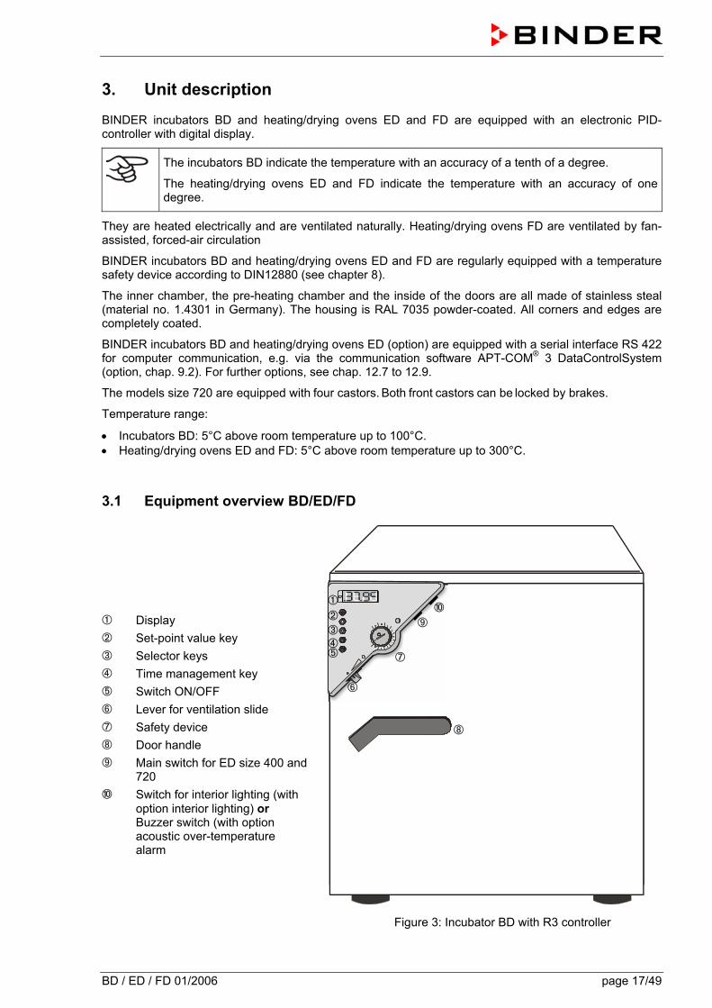
3.1 Equipment overview BD/ED/FD â Display ã Set-point value key ä Selector keys å Time management key æ Switch ON/OFF ç Lever for ventilation slide è Safety device é Door handle ê Main switch for ED size 400 and
720 ë Switch for interior lighting (with
option interior lighting) or Buzzer switch (with option acoustic over-temperature alarm
Figure 3: Incubator BD with R3 controller
âãäåæ
ç
ê
è
é
ë
BD / ED / FD 01/2006 page 18/49
4. Scope of delivery, transportation, storage, and installation
4.1 Unpacking, and checking equipment and scope of delivery
After having unpacked, please check the unit and its optional accessories, if any, based on the delivery note for completeness and for transportation damage. If transportation damage has occurred, immediately inform the carrier.
Please remove any transportation protection devices and adhesives in / on the unit and at the doors and take out the operating manuals and accessory equipment.
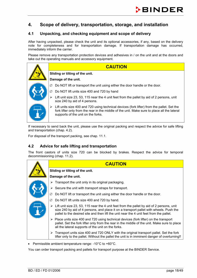
CAUTION
Sliding or tilting of the unit.
Damage of the unit.
∅ Do NOT lift or transport the unit using either the door handle or the door.
∅ Do NOT lift units size 400 and 720 by hand
Lift unit size 23, 53, 115 near the 4 unit feet from the pallet by aid of 2 persons, unit size 240 by aid of 4 persons.
Lift units size 400 and 720 using technical devices (fork lifter) from the pallet. Set the fork lifter only from the rear in the middle of the unit. Make sure to place all the lateral supports of the unit on the forks.
If necessary to send back the unit, please use the original packing and respect the advice for safe lifting and transportation (chap. 4.2).
For disposal of the transport packing, see chap. 11.1.
4.2 Advice for safe lifting and transportation The front castors of units size 720 can be blocked by brakes. Respect the advice for temporal decommissioning (chap. 11.2).
CAUTION
Sliding or tilting of the unit.
Damage of the unit.
Transport the unit only in its original packaging.
Secure the unit with transport straps for transport.
∅ Do NOT lift or transport the unit using either the door handle or the door.
∅ Do NOT lift units size 400 and 720 by hand.
Lift unit size 23, 53, 115 near the 4 unit feet from the pallet by aid of 2 persons, unit size 240 by aid of 4 persons, and place it on a transport pallet with wheels. Push the pallet to the desired site and then lift the unit near the 4 unit feet from the pallet.
Place units size 400 and 720 using technical devices (fork lifter) on the transport pallet. Set the fork lifter only from the rear in the middle of the unit. Make sure to place all the lateral supports of the unit on the forks.
Transport units size 400 and 720 ONLY with the original transport pallet. Set the fork lifter only to the pallet. Without the pallet the unit is in imminent danger of overturning!!
• Permissible ambient temperature range: -10°C to +60°C.
You can order transport packing and pallets for transport purpose at the BINDER Service.
BD / ED / FD 01/2006 page 19/49
4.3 Storage
Intermediate storage of the unit is possible in a closed and dry room. Respect the advice for temporal decommissioning (chap. 11.2).
• Permissible ambient temperature range: -10°C to +60°C.
• Permissible ambient humidity: max. 70 % r.H., non-condensing
If following storage in a cold location the unit is transferred to the installation site for start-up, condensation is possible. Wait at least one hour until the oven has attained ambient temperature and is completely dry.
4.4 Location of installation and ambient conditions
Set up the incubators BD or the heating/drying oven ED / FD on a plane and non-flammable surface, free from vibration at a well-ventilated, dry location and align it using a spirit level. The site of installation must be capable of supporting the unit’s weight (see technical data, chap. 12.4 to 12.6).
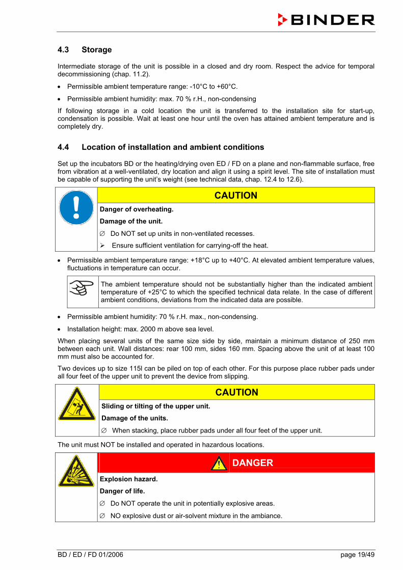
CAUTION
Danger of overheating.
Damage of the unit.
∅ Do NOT set up units in non-ventilated recesses.
Ensure sufficient ventilation for carrying-off the heat.
• Permissible ambient temperature range: +18°C up to +40°C. At elevated ambient temperature values, fluctuations in temperature can occur.
The ambient temperature should not be substantially higher than the indicated ambient temperature of +25°C to which the specified technical data relate. In the case of different ambient conditions, deviations from the indicated data are possible.
• Permissible ambient humidity: 70 % r.H. max., non-condensing.
• Installation height: max. 2000 m above sea level.
When placing several units of the same size side by side, maintain a minimum distance of 250 mm between each unit. Wall distances: rear 100 mm, sides 160 mm. Spacing above the unit of at least 100 mm must also be accounted for.
Two devices up to size 115l can be piled on top of each other. For this purpose place rubber pads under all four feet of the upper unit to prevent the device from slipping.
CAUTION
Sliding or tilting of the upper unit.
Damage of the units.
∅ When stacking, place rubber pads under all four feet of the upper unit.
The unit must NOT be installed and operated in hazardous locations.
DANGER
Explosion hazard.
Danger of life.
∅ Do NOT operate the unit in potentially explosive areas.
∅ NO explosive dust or air-solvent mixture in the ambiance.
BD / ED / FD 01/2006 page 20/49
5. Installation of the equipment
5.1 Electrical connection • BD all volumes, ED up to volume 240, FD all volumes:
Shockproof plug, mains voltage 230 V (1N~) +/- 10 %, 50/60 Hz
Fixed mains connection cable of 1800 mm in length
• ED 400, ED 720:
CEE plug 5 poles, mains voltage 400 V (3N~) +/- 10 %, 50/60 Hz
Fixed mains connection cable of 2700 mm in length
• BD 53-UL all volumes, ED 23-UL, FD 23-UL:
NEMA plug 5-15P, mains voltage 115 V (1N~) +/- 10 %, 60 Hz
Fixed mains connection cable of 1800 mm in length
• ED 53-UL, ED 115-UL, FD 53-UL, FD 115-UL:
NEMA plug 5-20P, mains voltage 115 V (1N~) +/- 10 %, 60 Hz
Fixed mains connection cable of 1800 mm in length
• ED 240-UL, ED 400-UL, ED 720-UL, FD 240-UL:
NEMA plug L21-20P, mains voltage 208 V (3N~) +/- 10 %, 60 Hz
Fixed mains connection cable of 2700 mm in length
• Prior to connection and start-up, check the mains voltage. Compare the values to the data specified on the type plate of the unit (unit front behind the door bottom left-hand, or at the unit side, chap. 1.4).
• When connecting, please observe the regulations specified by the local electricity supply company and as well as the VDE directives (for Germany)
• Pollution degree (acc. to IEC 1010-1): 2 • Over-voltage category (acc. to IEC 1010-1): II
CAUTION
Danger of incorrect mains voltage.
Damage of the equipment.
Check the mains voltage before connection and start-up.
Compare the mains voltage to the data indicated on the type plate.
See also electrical data (chap. 12.4 to 12.6).
5.2 Connection to a suction plant (optional)
When directly connecting a suction plant the spatial temperature exactitude, the heating-up and the recovering times and the maximum temperature will be negatively influenced. So no suction plant should be directly connected to the outgoing air pipe.
Active suction from the oven must only be effected together with extraneous air. Perforate the connecting piece to the suction device or place an exhaust funnel at some distance to the outgoing air pipe.
BD / ED / FD 01/2006 page 21/49
CAUTION
The exhaust duct will become hot during operation. Danger of burning. ∅ Do NOT touch the exhaust duct during operation.
6. Start up
6.1 Switching on the unit
1. Insert plug into socket (chap. 5.1).
2. Switch on ED units of sizes 400 and 720 at the main switch (10)
The green “Standby“ LED illuminates
3. Press until the display lights up.
The controller is now in normal display (actual value display).
If the oven is operating (time functions “Continuous operation”, or “Timer operation” with the set time just running down chap. 7.3), the actual temperature value (example: 22°C) is displayed
If the oven is in time function “Timer operation” with no time programmed or the set time run-off (chap. 7.3), the unit is inactive (no heating). The display alternately shows the actual temperature value (example: 22°C) and “tOff”:
6.2 Heating operation display
The heating and fan (with FD) are active as soon as the red heating control light in the bottom right corner of the display slowly begins to flash depending on the heat requirement (example: 70°C).
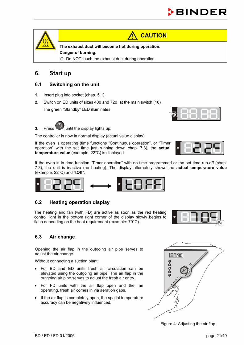
6.3 Air change Opening the air flap in the outgoing air pipe serves to adjust the air change.
Without connecting a suction plant:
• For BD and ED units fresh air circulation can be elevated using the outgoing air pipe. The air flap in the outgoing air pipe serves to adjust the fresh air entry.
• For FD units with the air flap open and the fan operating, fresh air comes in via aeration gaps.
• If the air flap is completely open, the spatial temperature accuracy can be negatively influenced.
Figure 4: Adjusting the air flap
BD / ED / FD 01/2006 page 22/49
7. Controller setting
7.1 Display / entry of temperature set-point (without ramp function)
Controller setting is identical on both the ED/FD and the BD. The temperature controllers only differ in their temperature range.
The unit is operating, the controller is in normal display (actual value display). The actual temperature value (example: 22°C) is displayed:
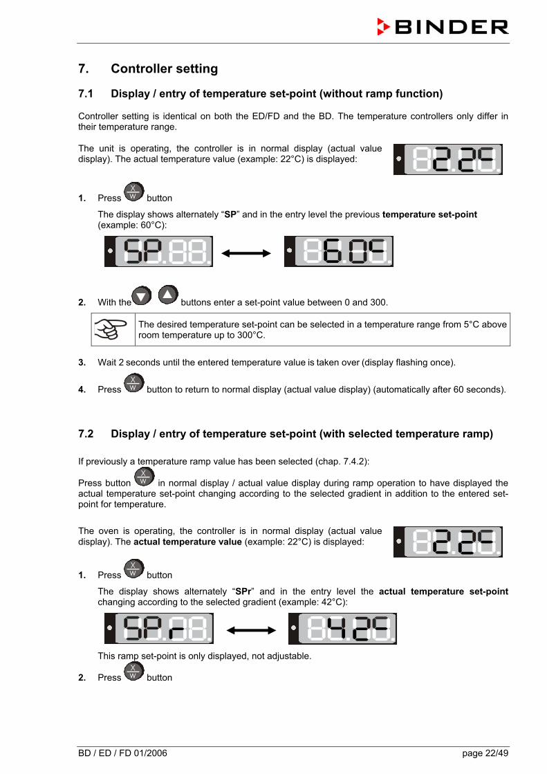
1. Press button
The display shows alternately “SP” and in the entry level the previous temperature set-point (example: 60°C):
2. With the buttons enter a set-point value between 0 and 300.
The desired temperature set-point can be selected in a temperature range from 5°C above room temperature up to 300°C.
3. Wait 2 seconds until the entered temperature value is taken over (display flashing once).
4. Press button to return to normal display (actual value display) (automatically after 60 seconds).
7.2 Display / entry of temperature set-point (with selected temperature ramp) If previously a temperature ramp value has been selected (chap. 7.4.2):
Press button in normal display / actual value display during ramp operation to have displayed the actual temperature set-point changing according to the selected gradient in addition to the entered set-point for temperature.
The oven is operating, the controller is in normal display (actual value display). The actual temperature value (example: 22°C) is displayed:
1. Press button
The display shows alternately “SPr” and in the entry level the actual temperature set-point changing according to the selected gradient (example: 42°C):
This ramp set-point is only displayed, not adjustable.
2. Press button

BD / ED / FD 01/2006 page 23/49
The display shows alternately “SP” and in the entry level the previous temperature set-point (example: 60°C):
3. With the buttons enter a set-point value between 0 and 300.
The desired temperature set-point can be selected in a temperature range from 5°C above room temperature up to 300°C.
4. Wait 2 seconds until the entered temperature value is taken over (display flashing once).
5. Press button to return to normal display / actual value display (automatically after 60 seconds).
7.3 Time functions: Continuous operation and Timer operation
Press the time management button .
The timer indicates its current time function. There are two possible time functions: Continuous operation
The display shows alternately “t1” (time function) and the time function “Continuous operation” “t inf”:
The heating and fan (with FD) are permanently active, independent of the timer setting. Timer operation
The display shows alternately “t1” (time function) and the running-down time or “tOff”:
or
Remaining time (example: 28 Min.) – Timer running down
Heating and fan (with FD) are active until the timer has run-down.
Timer not programmed or run-down “t off”
If the timer has run-down, heating and fan (with FD) are permanently off.
Press button to return to normal display (actual value display) (automatically after 60 seconds).
BD / ED / FD 01/2006 page 24/49
7.3.1 Switching between Continuous operation and Timer operation
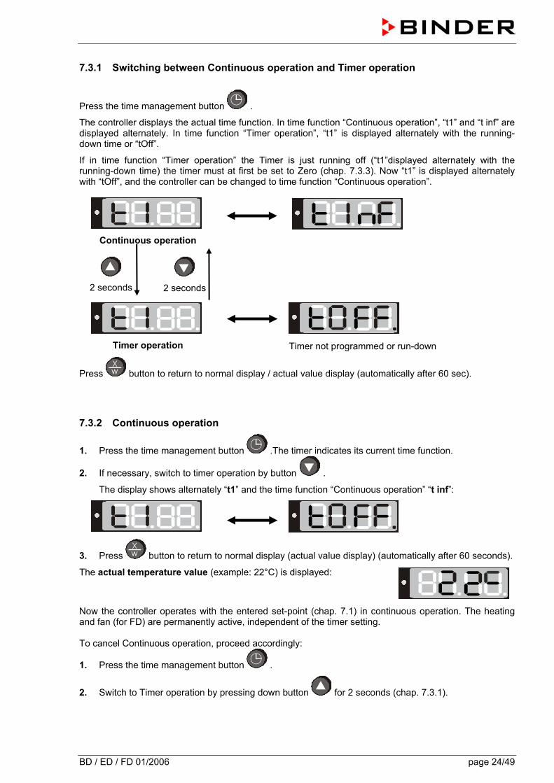
Press the time management button .
The controller displays the actual time function. In time function “Continuous operation”, “t1” and “t inf” are displayed alternately. In time function “Timer operation”, “t1” is displayed alternately with the running-down time or “tOff”.
If in time function “Timer operation” the Timer is just running off (“t1”displayed alternately with the running-down time) the timer must at first be set to Zero (chap. 7.3.3). Now “t1” is displayed alternately with “tOff”, and the controller can be changed to time function “Continuous operation”.
Continuous operation
2 seconds
2 seconds
Timer operation
Timer not programmed or run-down
Press button to return to normal display / actual value display (automatically after 60 sec).
7.3.2 Continuous operation
1. Press the time management button .The timer indicates its current time function.
2. If necessary, switch to timer operation by button .
The display shows alternately “t1” and the time function “Continuous operation” “t inf”:
3. Press button to return to normal display (actual value display) (automatically after 60 seconds).
The actual temperature value (example: 22°C) is displayed:
Now the controller operates with the entered set-point (chap. 7.1) in continuous operation. The heating and fan (for FD) are permanently active, independent of the timer setting. To cancel Continuous operation, proceed accordingly:
1. Press the time management button .
2. Switch to Timer operation by pressing down button for 2 seconds (chap. 7.3.1).
BD / ED / FD 01/2006 page 25/49
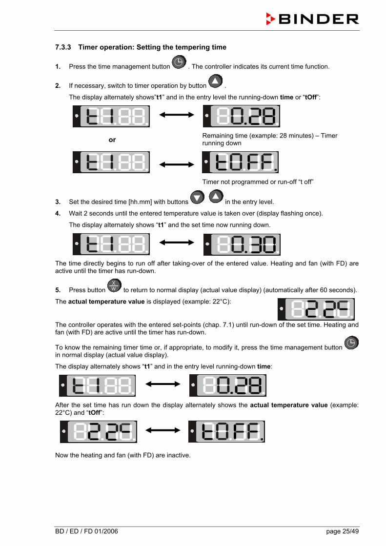
7.3.3 Timer operation: Setting the tempering time
1. Press the time management button . The controller indicates its current time function.
2. If necessary, switch to timer operation by button .
The display alternately shows”t1” and in the entry level the running-down time or “tOff”:
or
Remaining time (example: 28 minutes) – Timer running down
Timer not programmed or run-off “t off”
3. Set the desired time [hh.mm] with buttons in the entry level.
4. Wait 2 seconds until the entered temperature value is taken over (display flashing once).
The display alternately shows “t1” and the set time now running down.
The time directly begins to run off after taking-over of the entered value. Heating and fan (with FD) are active until the timer has run-down.
5. Press button to return to normal display (actual value display) (automatically after 60 seconds).
The actual temperature value is displayed (example: 22°C):
The controller operates with the entered set-points (chap. 7.1) until run-down of the set time. Heating and fan (with FD) are active until the timer has run-down.
To know the remaining timer time or, if appropriate, to modify it, press the time management button in normal display (actual value display).
The display alternately shows “t1” and in the entry level running-down time:
After the set time has run down the display alternately shows the actual temperature value (example: 22°C) and “tOff”:
Now the heating and fan (with FD) are inactive.
BD / ED / FD 01/2006 page 26/49
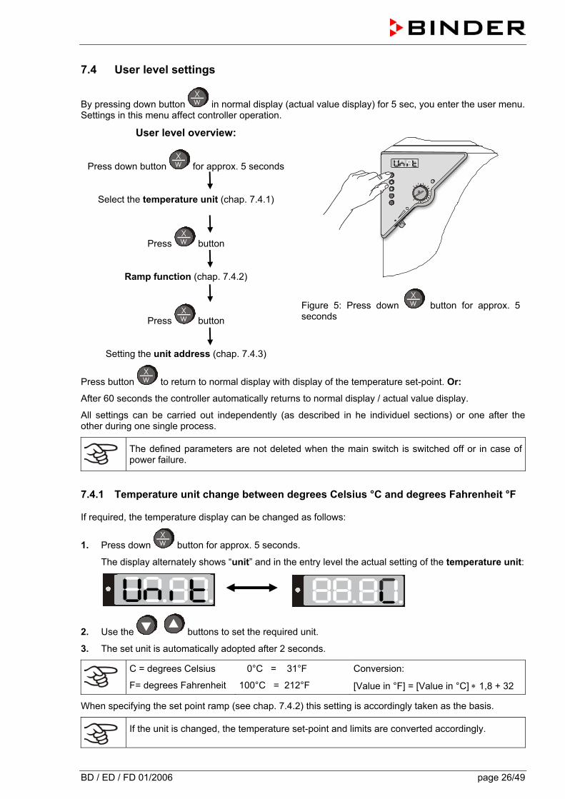
7.4 User level settings
By pressing down button in normal display (actual value display) for 5 sec, you enter the user menu. Settings in this menu affect controller operation.
User level overview:
Press down button for approx. 5 seconds
Select the temperature unit (chap. 7.4.1)
Press button
Ramp function (chap. 7.4.2)
Press button
Setting the unit address (chap. 7.4.3)
Figure 5: Press down button for approx. 5 seconds
Press button to return to normal display with display of the temperature set-point. Or:
After 60 seconds the controller automatically returns to normal display / actual value display.
All settings can be carried out independently (as described in he individuel sections) or one after the other during one single process.
The defined parameters are not deleted when the main switch is switched off or in case of power failure.
7.4.1 Temperature unit change between degrees Celsius °C and degrees Fahrenheit °F
If required, the temperature display can be changed as follows:
1. Press down button for approx. 5 seconds.
The display alternately shows “unit” and in the entry level the actual setting of the temperature unit:
2. Use the buttons to set the required unit.
3. The set unit is automatically adopted after 2 seconds.
C = degrees Celsius
F= degrees Fahrenheit 0°C = 31°F
100°C = 212°F Conversion:
[Value in °F] = [Value in °C] ∗ 1,8 + 32
When specifying the set point ramp (see chap. 7.4.2) this setting is accordingly taken as the basis.
If the unit is changed, the temperature set-point and limits are converted accordingly.
BD / ED / FD 01/2006 page 27/49
7.4.2 Enter a temperature ramp
Temperature ramps can be programmed in order to extend heating up times. This may be necessary in some cases, in order to prevent temperature stresses in the material during the heating up phase. Temperature ramps should only be used if required. The use of temperature ramps may result in the heating up times being considerably slowed down.
The entry in °C/min or in °F/min meaning the nominal value gradient and limits the maximum temperature increase to this value. Due to the heat and evaporation energy assumed by the drying material, smaller temperature gradients may also result.
A temperature ramp proceeds from the previously entered to a new set-point. The temperature must have adjusted to the start set-point. Enter settings in 3 steps:
1. Enter set-point of ramp start temperature. Let temperature adjust to this set-point temperature.
2. Set ramp to the desired gradient. The gradient can then be set between 1° and 10° per minute. A heat-up rate of 4°C/min. can be regarded as a realistic maximum.
3. Enter set-point (final ramp temperature).
The ramp should only be set if required. The setting “0” means ramp function switched off. The unit is being heated at maximum heat output.
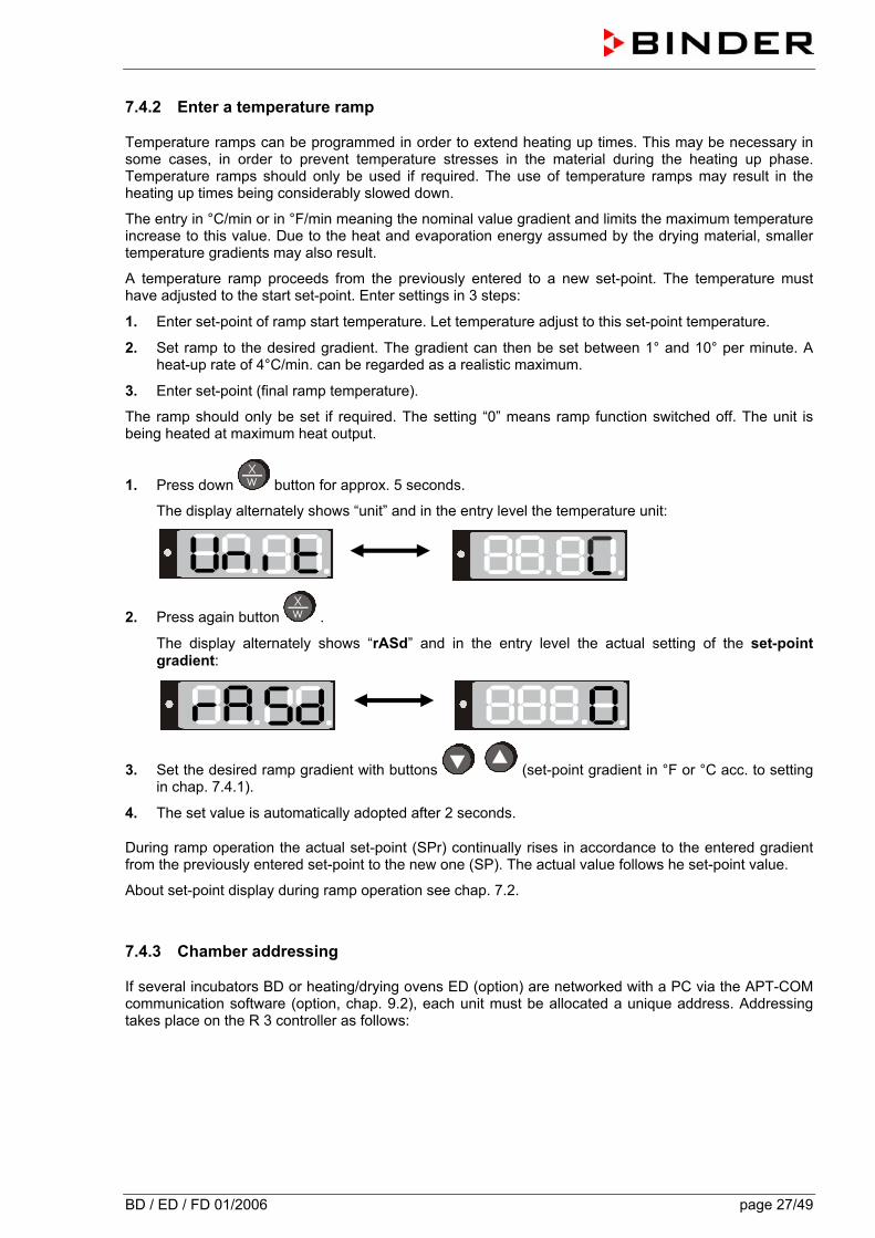
1. Press down button for approx. 5 seconds.
The display alternately shows “unit” and in the entry level the temperature unit:
2. Press again button .
The display alternately shows “rASd” and in the entry level the actual setting of the set-point gradient:
3. Set the desired ramp gradient with buttons (set-point gradient in °F or °C acc. to setting in chap. 7.4.1).
4. The set value is automatically adopted after 2 seconds.
During ramp operation the actual set-point (SPr) continually rises in accordance to the entered gradient from the previously entered set-point to the new one (SP). The actual value follows he set-point value.
About set-point display during ramp operation see chap. 7.2.
7.4.3 Chamber addressing
If several incubators BD or heating/drying ovens ED (option) are networked with a PC via the APT-COM communication software (option, chap. 9.2), each unit must be allocated a unique address. Addressing takes place on the R 3 controller as follows:
BD / ED / FD 01/2006 page 28/49
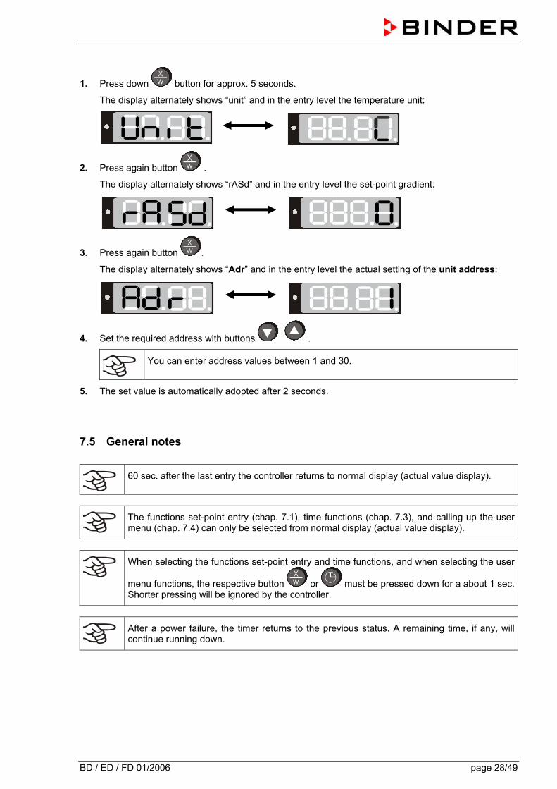
1. Press down button for approx. 5 seconds.
The display alternately shows “unit” and in the entry level the temperature unit:
2. Press again button .
The display alternately shows “rASd” and in the entry level the set-point gradient:
3. Press again button .
The display alternately shows “Adr” and in the entry level the actual setting of the unit address:
4. Set the required address with buttons .
You can enter address values between 1 and 30.
5. The set value is automatically adopted after 2 seconds.
7.5 General notes
60 sec. after the last entry the controller returns to normal display (actual value display).
The functions set-point entry (chap. 7.1), time functions (chap. 7.3), and calling up the user menu (chap. 7.4) can only be selected from normal display (actual value display).
When selecting the functions set-point entry and time functions, and when selecting the user
menu functions, the respective button or must be pressed down for a about 1 sec. Shorter pressing will be ignored by the controller.
After a power failure, the timer returns to the previous status. A remaining time, if any, will continue running down.
BD / ED / FD 01/2006 page 29/49
8. Safety devices
8.1 Temperature safety device class 2 (DIN 12880) ED, FD The temperature safety device class 2 protects the unit, its environment and the charging material against impermissible excess temperatures.
Please also observe the regulations BGR 120 of the German professional association of the chemical industry (formerly ZH 1/119 laboratory guidelines of the employers’ liability insurance association) (for Germany).
In the event of a fault in the temperature controller, the safety device (7) permanently switches off the unit. This status is reported visually by the indicator lamp (7a) and, in case of the option acoustic alarm with activated buzzer (chap. 9.1), by the buzzer sounding.
The operation of the safety device (7) is checked by moving it slowly anti-clockwise until it is switched off. The safety device cut-off is reported visually by the indicator lamp (7a) and, in case of the option acoustic alarm with activated buzzer (chap. 9.1), by the buzzer sounding.
The safety device is then released again by pressing the reset button (7b) and the unit is switched on as described.
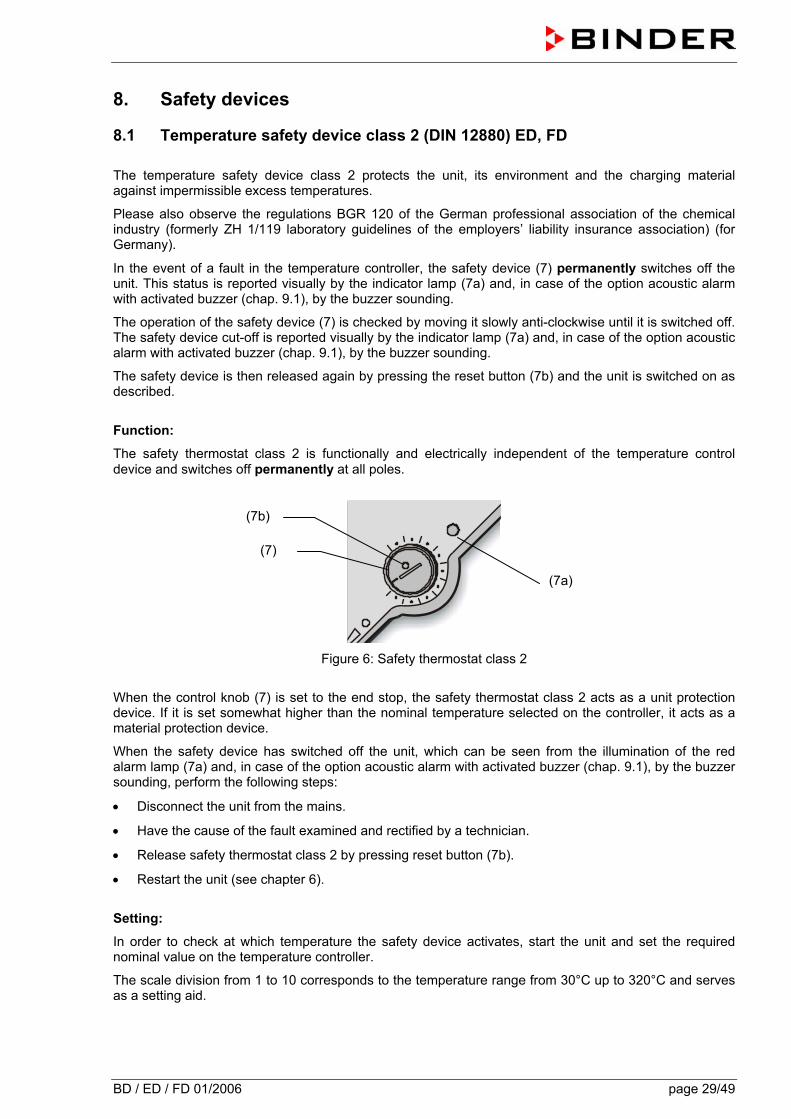
Function:
The safety thermostat class 2 is functionally and electrically independent of the temperature control device and switches off permanently at all poles.
Figure 6: Safety thermostat class 2
When the control knob (7) is set to the end stop, the safety thermostat class 2 acts as a unit protection device. If it is set somewhat higher than the nominal temperature selected on the controller, it acts as a material protection device.
When the safety device has switched off the unit, which can be seen from the illumination of the red alarm lamp (7a) and, in case of the option acoustic alarm with activated buzzer (chap. 9.1), by the buzzer sounding, perform the following steps:
• Disconnect the unit from the mains.
• Have the cause of the fault examined and rectified by a technician.
• Release safety thermostat class 2 by pressing reset button (7b).
• Restart the unit (see chapter 6).
Setting:
In order to check at which temperature the safety device activates, start the unit and set the required nominal value on the temperature controller.
The scale division from 1 to 10 corresponds to the temperature range from 30°C up to 320°C and serves as a setting aid.
(7)
(7a)
(7b)
BD / ED / FD 01/2006 page 30/49
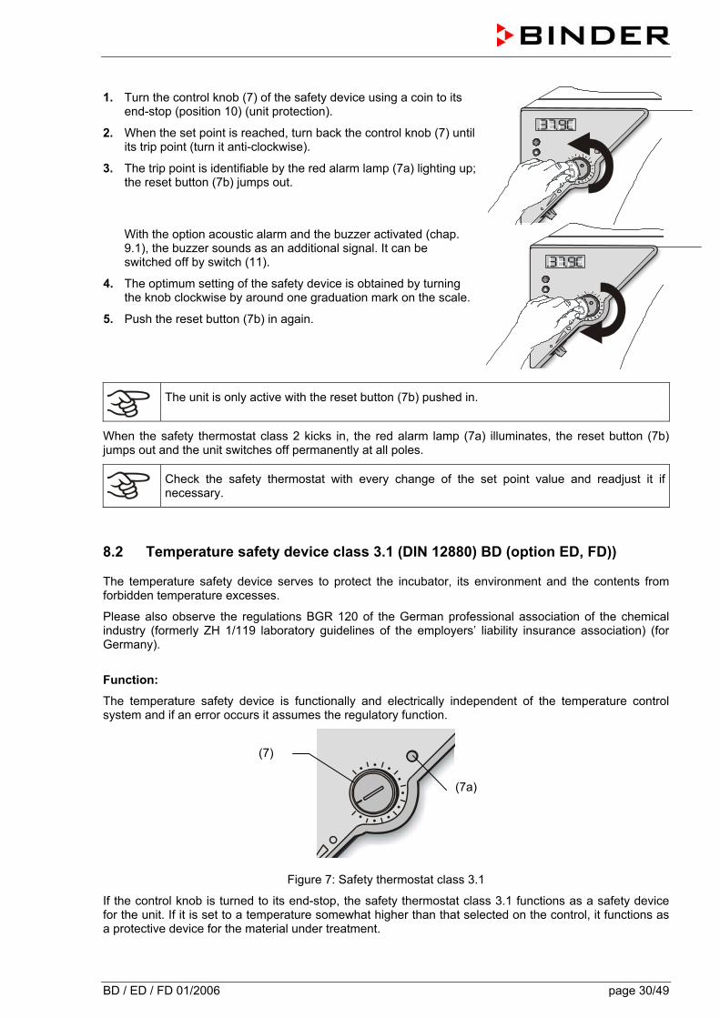
1. Turn the control knob (7) of the safety device using a coin to its
end-stop (position 10) (unit protection).
2. When the set point is reached, turn back the control knob (7) until its trip point (turn it anti-clockwise).
3. The trip point is identifiable by the red alarm lamp (7a) lighting up; the reset button (7b) jumps out.
With the option acoustic alarm and the buzzer activated (chap. 9.1), the buzzer sounds as an additional signal. It can be switched off by switch (11).
4. The optimum setting of the safety device is obtained by turning the knob clockwise by around one graduation mark on the scale.
5. Push the reset button (7b) in again.
The unit is only active with the reset button (7b) pushed in.
When the safety thermostat class 2 kicks in, the red alarm lamp (7a) illuminates, the reset button (7b) jumps out and the unit switches off permanently at all poles.
Check the safety thermostat with every change of the set point value and readjust it if necessary.
8.2 Temperature safety device class 3.1 (DIN 12880) BD (option ED, FD))
The temperature safety device serves to protect the incubator, its environment and the contents from forbidden temperature excesses.
Please also observe the regulations BGR 120 of the German professional association of the chemical industry (formerly ZH 1/119 laboratory guidelines of the employers’ liability insurance association) (for Germany).
Function:
The temperature safety device is functionally and electrically independent of the temperature control system and if an error occurs it assumes the regulatory function.
Figure 7: Safety thermostat class 3.1
If the control knob is turned to its end-stop, the safety thermostat class 3.1 functions as a safety device for the unit. If it is set to a temperature somewhat higher than that selected on the control, it functions as a protective device for the material under treatment.
(7)
(7a)
BD / ED / FD 01/2006 page 31/49
If the safety device has assumed the regulation function (identifiable by the red alarm lamp (7a) lighting up and, in case of the option acoustic alarm with activated buzzer (chap. 9.1), by the buzzer sounding), proceed as follows:
• Disconnect the unit from the mains.
• Have the cause of the fault examined and rectified by a technician.
• Restart the unit (see chapter 6).
Adjustment:
To check the response temperature of the safety thermostat class 3.1, switch on the unit and set the desired set point at the temperature controller.
The scale division from 1 to 10 corresponds to the temperature range from 0°C to 120°C (BD) or from 63°C to 350°C (ED or FD, option) and serves as a setting aid.
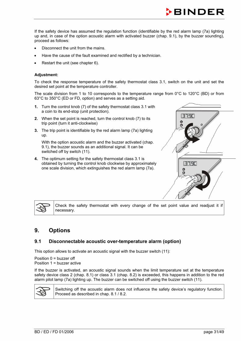
1. Turn the control knob (7) of the safety thermostat class 3.1 with a coin to its end-stop (unit protection).
2. When the set point is reached, turn the control knob (7) to its trip point (turn it anti-clockwise)
3. The trip point is identifiable by the red alarm lamp (7a) lighting up.
With the option acoustic alarm and the buzzer activated (chap. 9.1), the buzzer sounds as an additional signal. It can be switched off by switch (11).
4. The optimum setting for the safety thermostat class 3.1 is obtained by turning the control knob clockwise by approximately one scale division, which extinguishes the red alarm lamp (7a).
Check the safety thermostat with every change of the set point value and readjust it if necessary.
9. Options
9.1 Disconnectable acoustic over-temperature alarm (option)
This option allows to activate an acoustic signal with the buzzer switch (11):
Position 0 = buzzer off Position 1 = buzzer active
If the buzzer is activated, an acoustic signal sounds when the limit temperature set at the temperature safety device class 2 (chap. 8.1) or class 3.1 (chap. 8.2) is exceeded, this happens in addition to the red alarm pilot lamp (7a) lighting up. The buzzer can be switched off using the buzzer switch (11).
Switching off the acoustic alarm does not influence the safety device’s regulatory function. Proceed as described in chap. 8.1 / 8.2.
BD / ED / FD 01/2006 page 32/49
9.2 Communication software APT-COM® 3 DataControlSystem (BD, option ED)
The oven is regularly equipped with a serial interface RS 422 to which the BINDER communication software APT-COM® 3 DataControlSystem can be connected. The connection to a computer is established using the unit interface via an interface converter RS 422 / RS 232.
In adjustable intervals the actual temperature, and fan speed values are put out. Programming can be performed graphically via PC. Up to 30 chambers with RS 422 interface can be cross linked. Further information can be obtained in the operating manual of the BINDER communication software APT-COM.
Pin allocation of the RS 422 interface:
pin 2: RxD (+) pin 3: TxD (+) pin 4: RxD (-) pin 5: TxD (-) pin 7: Ground
If several incubators BD or heating/drying ovens ED (option) are to be recorded via a PC, each one must be allocated a unique address. Addressing is performed via the R3 controller (see chapter 7.4.3 ).
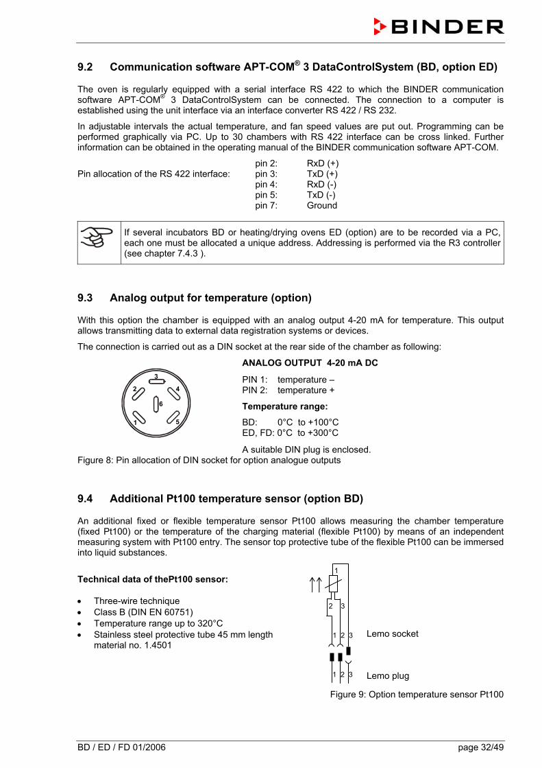
9.3 Analog output for temperature (option)
With this option the chamber is equipped with an analog output 4-20 mA for temperature. This output allows transmitting data to external data registration systems or devices.
The connection is carried out as a DIN socket at the rear side of the chamber as following:
ANALOG OUTPUT 4-20 mA DC
PIN 1: temperature – PIN 2: temperature +
Temperature range:
BD: 0°C to +100°C ED, FD: 0°C to +300°C
A suitable DIN plug is enclosed. Figure 8: Pin allocation of DIN socket for option analogue outputs
9.4 Additional Pt100 temperature sensor (option BD)
An additional fixed or flexible temperature sensor Pt100 allows measuring the chamber temperature (fixed Pt100) or the temperature of the charging material (flexible Pt100) by means of an independent measuring system with Pt100 entry. The sensor top protective tube of the flexible Pt100 can be immersed into liquid substances.
Technical data of thePt100 sensor: • Three-wire technique • Class B (DIN EN 60751) • Temperature range up to 320°C • Stainless steel protective tube 45 mm length
material no. 1.4501
Lemo socket Lemo plug
Figure 9: Option temperature sensor Pt100
1 2 3
1 2 3
2 3
1
1
2
3
4
5
6
BD / ED / FD 01/2006 page 33/49
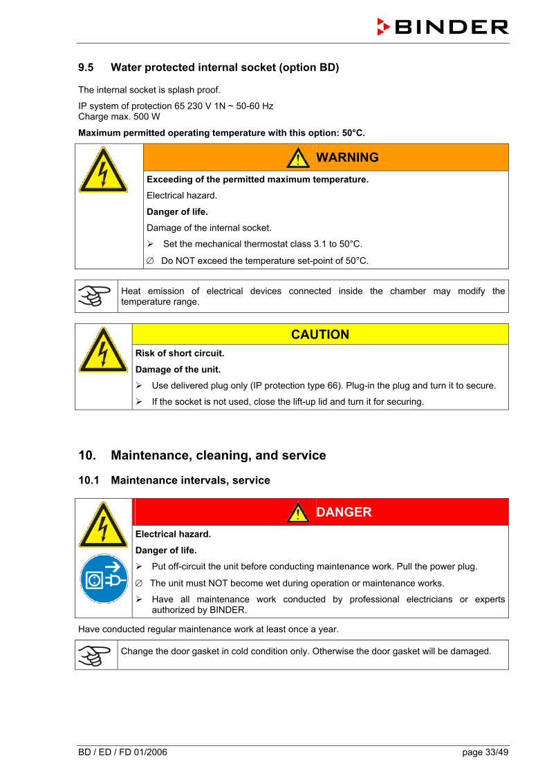
9.5 Water protected internal socket (option BD)
The internal socket is splash proof.
IP system of protection 65 230 V 1N ~ 50-60 Hz Charge max. 500 W
Maximum permitted operating temperature with this option: 50°C.
WARNING
Exceeding of the permitted maximum temperature.
Electrical hazard.
Danger of life.
Damage of the internal socket.
Set the mechanical thermostat class 3.1 to 50°C.
∅ Do NOT exceed the temperature set-point of 50°C.
Heat emission of electrical devices connected inside the chamber may modify the temperature range.
CAUTION
Risk of short circuit.
Damage of the unit.
Use delivered plug only (IP protection type 66). Plug-in the plug and turn it to secure.
If the socket is not used, close the lift-up lid and turn it for securing.
10. Maintenance, cleaning, and service
10.1 Maintenance intervals, service
DANGER
Electrical hazard.
Danger of life.
Put off-circuit the unit before conducting maintenance work. Pull the power plug.
∅ The unit must NOT become wet during operation or maintenance works.
Have all maintenance work conducted by professional electricians or experts authorized by BINDER.
Have conducted regular maintenance work at least once a year.
Change the door gasket in cold condition only. Otherwise the door gasket will be damaged.
BD / ED / FD 01/2006 page 34/49
We recommend entering a maintenance agreement. Please consult the BINDER service department.
BINDER telephone hotline: +49 (0) 7462 2005 555 BINDER fax hotline: +49 (0) 7462 2005 93555 BINDER e-mail hotline: [email protected] BINDER service hotline USA: +1 866 816 8191 (toll-free in the USA) BINDER Asia Pacific: + 603 6204 2855 BINDER Internet homepage http://www.binder-world.com BINDER address BINDER GmbH, post office box 102, D-78502 Tuttlingen International customers, please contact your local BINDER distributor.
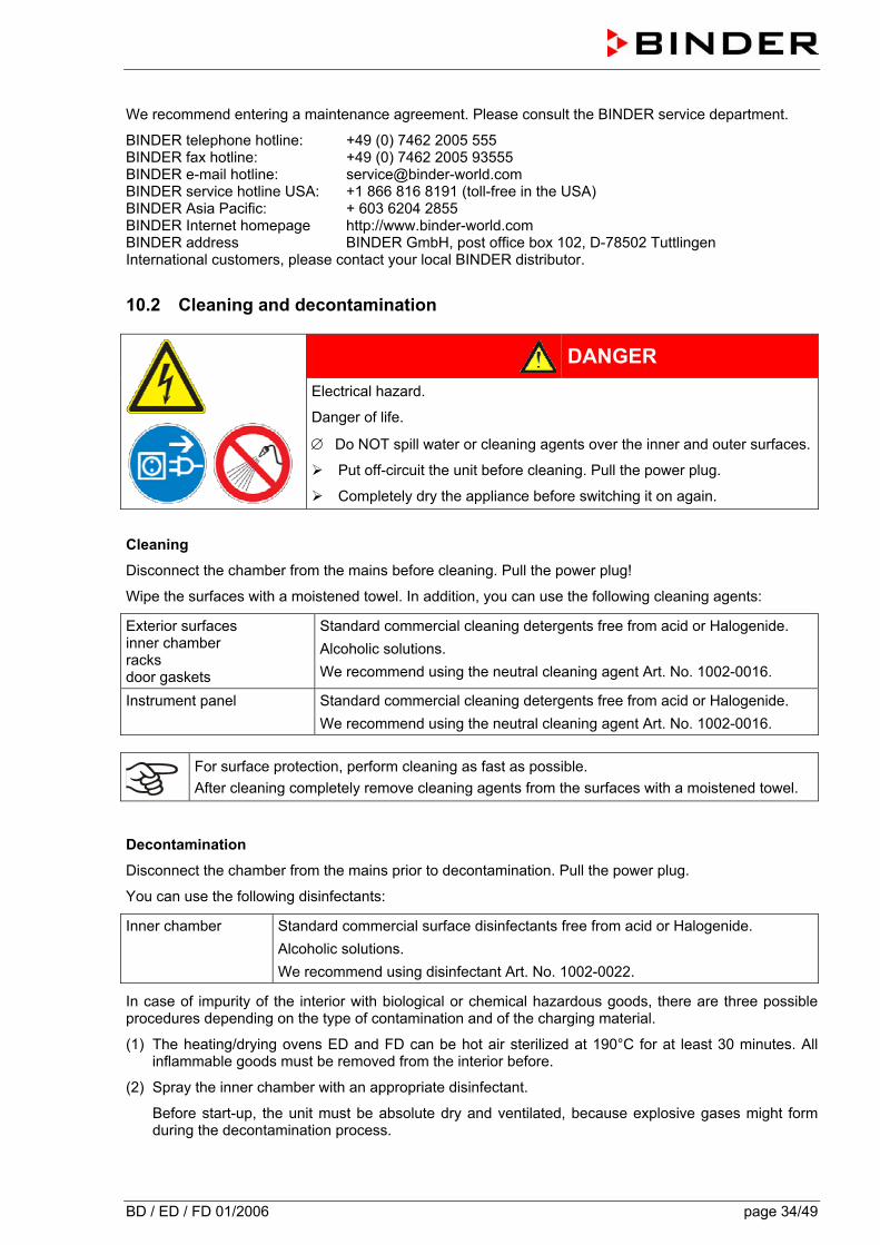
10.2 Cleaning and decontamination
DANGER
Electrical hazard.
Danger of life.
∅ Do NOT spill water or cleaning agents over the inner and outer surfaces.
Put off-circuit the unit before cleaning. Pull the power plug.
Completely dry the appliance before switching it on again.
Cleaning
Disconnect the chamber from the mains before cleaning. Pull the power plug!
Wipe the surfaces with a moistened towel. In addition, you can use the following cleaning agents:
Exterior surfaces inner chamber racks door gaskets
Standard commercial cleaning detergents free from acid or Halogenide. Alcoholic solutions. We recommend using the neutral cleaning agent Art. No. 1002-0016.
Instrument panel Standard commercial cleaning detergents free from acid or Halogenide. We recommend using the neutral cleaning agent Art. No. 1002-0016.
For surface protection, perform cleaning as fast as possible. After cleaning completely remove cleaning agents from the surfaces with a moistened towel.
Decontamination
Disconnect the chamber from the mains prior to decontamination. Pull the power plug.
You can use the following disinfectants:
Inner chamber Standard commercial surface disinfectants free from acid or Halogenide. Alcoholic solutions. We recommend using disinfectant Art. No. 1002-0022.
In case of impurity of the interior with biological or chemical hazardous goods, there are three possible procedures depending on the type of contamination and of the charging material.
(1) The heating/drying ovens ED and FD can be hot air sterilized at 190°C for at least 30 minutes. All inflammable goods must be removed from the interior before.
(2) Spray the inner chamber with an appropriate disinfectant.
Before start-up, the unit must be absolute dry and ventilated, because explosive gases might form during the decontamination process.

BD / ED / FD 01/2006 page 35/49
(3) If necessary, have strongly contaminated inner chamber parts removed by an engineer for cleaning,
or have them exchanged. Sterilize the inner chamber parts in a sterilizer or autoclave.
With every decontamination method, ensure adequate personal safety.
CAUTION
Danger of corrosion.
Damage of the unit.
∅ Do NOT use acidic or chlorine cleaning detergents.
We recommend using the neutral cleaning agent Art. No. Art. Nr. 1002-0016 for a thorough and mild cleaning.
Any corrosive damage that might arise following use of other cleaning agents is excluded from liability by the BINDER GmbH.
11. Disposal
11.1 Disposal of the transport packing
Packing element Material Disposal Straps to fix packing on pallet Plastic Plastic recycling
Non-wood (compressed matchwood, IPPC standard)
Wood recycling Wooden transport box (option) with metal screws Metal Metal recycling Pallet (from size 115 on) Solid wood (IPPC standard) Wood recycling
Cardboard Paper recycling Transport box with metal clamps Metal Metal recycling Wooden sticks for stabilizing and for take out (from size 240 on)
Solid wood (IPPC standard) Wood recycling
Foamed plastic stuffing (pallet, top cover)
PE foam Plastic recycling
Top cover (from size 240 on) Cardboard Paper recycling Cardboard Paper recycling Take out
assistance (sizes 240 and 400 only)
Plastic Plastic recycling
Edge protection Styropor® Plastic recycling Protection of doors and racks PE foam Plastic recycling Bag for operating manual PE foil Plastic recycling Insulating air cushion foil (packing of optional accessories)
PE foil Plastic recycling
If recycling is impossible, all packing parts can also be disposed of in the household waste.
BD / ED / FD 01/2006 page 36/49
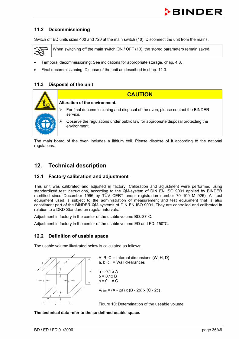
11.2 Decommissioning
Switch off ED units sizes 400 and 720 at the main switch (10). Disconnect the unit from the mains.
When switching off the main switch ON / OFF (10), the stored parameters remain saved.
• Temporal decommissioning: See indications for appropriate storage, chap. 4.3.
• Final decommissioning: Dispose of the unit as described in chap. 11.3.
11.3 Disposal of the unit
CAUTION
Alteration of the environment.
For final decommissioning and disposal of the oven, please contact the BINDER service.
Observe the regulations under public law for appropriate disposal protecting the environment.
The main board of the oven includes a lithium cell. Please dispose of it according to the national regulations.
12. Technical description
12.1 Factory calibration and adjustment
This unit was calibrated and adjusted in factory. Calibration and adjustment were performed using standardized test instructions, according to the QM-system of DIN EN ISO 9001 applied by BINDER (certified since December 1996 by TÜV CERT under registration number 70 100 M 926). All test equipment used is subject to the administration of measurement and test equipment that is also constituent part of the BINDER QM-systems of DIN EN ISO 9001. They are controlled and calibrated in relation to a DKD-Standard on regular intervals.
Adjustment in factory in the center of the usable volume BD: 37°C.
Adjustment in factory in the center of the usable volume ED and FD: 150°C.
12.2 Definition of usable space
The usable volume illustrated below is calculated as follows:
b
c
c
a
b
a
C
B
A
A, B, C = Internal dimensions (W, H, D) a, b, c = Wall clearances a = 0.1 x A b = 0.1x B c = 0.1 x C
VUSE = (A - 2a) x (B - 2b) x (C - 2c) Figure 10: Determination of the useable volume
The technical data refer to the so defined usable space.
BD / ED / FD 01/2006 page 37/49
Do NOT place samples outside this usable volume.
Do NOT load this volume more than half to enable sufficient airflow inside the chamber.
Do NOT divide the usable volume into separate parts with large area samples.
Do NOT place samples too close to each other in order to allow circulation between them and thus obtain a homogenous distribution of temperature.
12.3 Over current protection
Single-phase devices are protected by one miniature fuse against over current, accessible from the outside. The miniature fuse is located at the rear of the chamber below the strain relief of the power cord. The fuse holder is equipped with a fuse clip 5mm x 20 mm. (CUL-Version 6,3x32 mm). The fuse may be replaced only with a substitute of the same ratings. Refer to the technical data of the respective device type.
Three-phase devices are equipped with internal fuses not accessible from outside. If these fuses are blown, please inform an electronic engineer or the BINDER service.
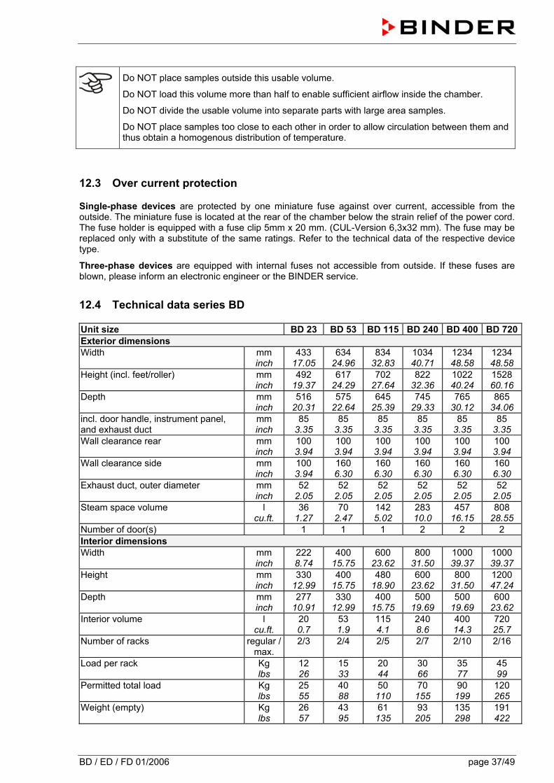
12.4 Technical data series BD
Unit size BD 23 BD 53 BD 115 BD 240 BD 400 BD 720Exterior dimensions Width mm
inch 433
17.05 634
24.96 834
32.83 1034 40.71
1234 48.58
1234 48.58
Height (incl. feet/roller) mm inch
492 19.37
617 24.29
702 27.64
822 32.36
1022 40.24
1528 60.16
Depth mm inch
516 20.31
575 22.64
645 25.39
745 29.33
765 30.12
865 34.06
incl. door handle, instrument panel, and exhaust duct
mm inch
85 3.35
85 3.35
85 3.35
85 3.35
85 3.35
85 3.35
Wall clearance rear mm inch
100 3.94
100 3.94
100 3.94
100 3.94
100 3.94
100 3.94
Wall clearance side mm inch
100 3.94
160 6.30
160 6.30
160 6.30
160 6.30
160 6.30
Exhaust duct, outer diameter mm inch
52 2.05
52 2.05
52 2.05
52 2.05
52 2.05
52 2.05
Steam space volume l cu.ft.
36 1.27
70 2.47
142 5.02
283 10.0
457 16.15
808 28.55
Number of door(s) 1 1 1 2 2 2 Interior dimensions Width mm
inch 222 8.74
400 15.75
600 23.62
800 31.50
1000 39.37
1000 39.37
Height mm inch
330 12.99
400 15.75
480 18.90
600 23.62
800 31.50
1200 47.24
Depth mm inch
277 10.91
330 12.99
400 15.75
500 19.69
500 19.69
600 23.62
Interior volume l cu.ft.
20 0.7
53 1.9
115 4.1
240 8.6
400 14.3
720 25.7
Number of racks regular / max.
2/3 2/4 2/5 2/7 2/10 2/16
Load per rack Kg lbs
12 26
15 33
20 44
30 66
35 77
45 99
Permitted total load Kg lbs
25 55
40 88
50 110
70 155
90 199
120 265
Weight (empty) Kg lbs
26 57
43 95
61 135
93 205
135 298
191 422
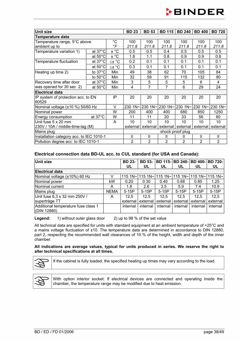
BD / ED / FD 01/2006 page 38/49
Unit size BD 23 BD 53 BD 115 BD 240 BD 400 BD 720Temperature data Temperature range, 5°C above ambient up to
°C °F
100 211.8
100 211.8
100 211.8
100 211.8
100 211.8
100 211.8
at 37°C ± °C 0.5 0.5 0.4 0.5 0.5 0.5 Temperature variation 1) at 50°C ± °C 1.8 1.1 0.8 0.9 0.9 0.8 at 37°C ≤± °C 0.2 0.1 0.1 0.1 0.1 0.1 Temperature fluctuation at 50°C ≤± °C 0.3 0.1 0.1 0.1 0.1 0.1 to 37°C Min 49 38 62 70 105 84 Heating up time 2) to 50°C Min 32 59 91 115 132 90 at 37°C Min 3 5 5 5 6 4 Recovery time after door
was opened for 30 sec 2) at 50°C Min 4 7 7 6 29 24 Electrical data IP system of protection acc. to EN 60529
IP 20 20 20 20 20 20
Nominal voltage (±10 %) 50/60 Hz V 230 1N~ 230 1N~ 230 1N~ 230 1N~ 230 1N~ 230 1N~Nominal power W 200 400 400 680 850 1250 Energy consumption at 37°C W 11 11 20 33 56 80 Unit fuse 5 x 20 mm 230V / 10A / middle-time-lag (M)
A 10 external
10 external
10 external
10 external
10 external
10 external
Mains plug shock proof plug Installation category acc. to IEC 1010-1 II II II II II II Pollution degree acc. to IEC 1010-1 2 2 2 2 2 2
Electrical connection data BD-UL acc. to CUL standard (for USA and Canada): Unit size BD 23-
UL BD 53-
UL BD 115-
UL BD 240-
UL BD 400-
UL BD 720-
UL Electrical data Nominal voltage (±10%) 60 Hz V 115 1N~ 115 1N~ 115 1N~ 115 1N~ 115 1N~ 115 1N~Nominal power kW 0.20 0.30 0.40 0.68 0.85 1.25 Nominal current A 1.8 2.6 3.5 5.9 7.4 10.9 Mains plug NEMA 5-15P 5-15P 5-15P 5-15P 5-15P 5-15P Unit fuse 6,3 x 32 mm 250V / superträge TT
A 12,5 external
12,5 external
12,5 external
12,5 external
12,5 external
12,5 external
Additional temperature fuse class 1 (DIN 12880)
internal internal internal internal internal internal
Legend: 1) without outer glass door 2) up to 98 % of the set value
All technical data are specified for units with standard equipment at an ambient temperature of +25°C and a mains voltage fluctuation of ±10. The temperature data are determined in accordance to DIN 12880, part 2, respecting the recommended wall clearances of 10 % of the height, width and depth of the inner chamber.
All indications are average values, typical for units produced in series. We reserve the right to alter technical specifications at all times.
If the cabinet is fully loaded, the specified heating up times may vary according to the load.
With option interior socket: If electrical devices are connected and operating inside the chamber, the temperature range may be modified due to heat emission.

BD / ED / FD 01/2006 page 39/49
12.5 Technical data series ED
Unit size ED 23 ED 53 ED 115 ED 240 ED 400 ED 720Exterior dimensions Width mm
inch 433
17.05 634
24.96 834
32.83 1034 40.71
1234 48.58
1234 48.58
Height (incl. feet/roller) mm inch
492 19.37
617 24.29
702 27.64
822 32.36
1022 40.24
1528 60.16
Depth mm inch
516 20.31
575 22.64
645 25.39
745 29.33
765 30.12
865 34.06
incl. door handle, instrument panel, and exhaust duct
mm inch
85 3.35
85 3.35
85 3.35
85 3.35
85 3.35
85 3.35
Wall clearance rear mm inch
100 3.94
100 3.94
100 3.94
100 3.94
100 3.94
100 3.94
Wall clearance side mm inch
100 3.94
160 6.30
160 6.30
160 6.30
160 6.30
160 6.30
Exhaust duct, outer diameter mm inch
52 2.05
52 2.05
52 2.05
52 2.05
52 2.05
52 2.05
Steam space volume l cu.ft.
36 1.27
70 2.47
142 5.02
283 10.0
457 16.15
808 28.55
Number of door(s) 1 1 1 2 2 2 Interior dimensions Width mm
inch 222 8.74
400 15.75
600 23.62
800 31.50
1000 39.37
1000 39.37
Height mm inch
330 12.99
400 15.75
480 18.90
600 23.62
800 31.50
1200 47.24
Depth mm inch
277 10.91
330 12.99
400 15.75
500 19.69
500 19.69
600 23.62
Interior volume l cu.ft.
20 0.7
53 1.9
115 4.1
240 8.6
400 14.3
720 25.7
Number of racks regular / max.
2/3 2/5 2/6 2/7 2/10 2/16
Load per rack Kg lbs
12 26
15 33
20 44
30 66
35 77
45 99
Permitted total load Kg lbs
25 55
40 88
50 110
70 155
90 199
120 265
Weight (empty) Kg lbs
22 49
42 93
57 126
86 190
125 276
174 384
Temperature data Temperature range, 5°C above ambient up to
°C °F
300 572
300 572
300 572
300 572
300 572
300 572
at 70°C ± °C 1.5 2 1.5 1.5 1.7 1.5 at 150°C ± °C 2.5 3.2 2.5 2.5 3 2.8
Temperature variation 1)
at 300°C ± °C 3.8 4.5 4.5 5.0 5.0 5.0 Temperature fluctuation ≤± °C 0.3 0.3 0.3 0.3 0.3 0.3
to 70°C Min 13 14 15 40 49 56 to 150°C Min 24 27 29 48 62 69
Heating up time 2)
to 250°C Min 35 61 66 61 74 80 at 70°C Min 2.5 2 2 5 4 4
at 150°C Min 5 6 9 13 20 14 Recovery time after door was open for 30 sec 2)
at 300°C Min 8 11 14 18 24 18 at 70°C x/h 8 8 12 11 11 10
at 150°C x/h 19 19 10 10 10 9 Air change
at 300°C x/h 20 20 10 9 9 8
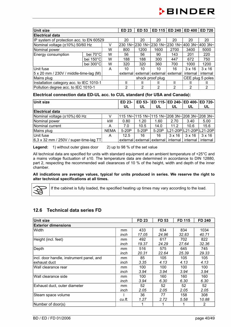
BD / ED / FD 01/2006 page 40/49
Unit size ED 23 ED 53 ED 115 ED 240 ED 400 ED 720Electrical data IP system of protection acc. to EN 60529 20 20 20 20 20 20 Nominal voltage (±10%) 50/60 Hz V 230 1N~ 230 1N~ 230 1N~ 230 1N~ 400 3N~ 400 3N~Nominal power W 800 1200 1600 2700 3400 5000
bei 70°C W 56 56 90 143 201 220 bei 150°C W 188 188 300 447 672 750
Energy consumption
bei 300°C W 320 320 360 700 1000 1200 Unit fuse 5 x 20 mm / 230V / middle-time-lag (M)
A 10 external
10 external
10 external
16 external
3 x 16internal
3 x 16internal
Mains plug shock proof plug CEE plug 5 polesInstallation category acc. to IEC 1010-1 II II II II II II Pollution degree acc. to IEC 1010-1 2 2 2 2 2 2
Electrical connection data ED-UL acc. to CUL standard (for USA and Canada): Unit size ED 23-
UL ED 53-
UL ED 115-
UL ED 240-
UL ED 400-
UL ED 720-
UL Electrical data Nominal voltage (±10%) 60 Hz V 115 1N~ 115 1N~ 115 1N~ 208 3N~ 208 3N~ 208 3N~Nominal power kW 0.80 1.20 1.60 2.70 3.40 5.00 Nominal current A 7.0 10.5 14.0 11.2 10.6 15.6 Mains plug NEMA 5-20P 5-20P 5-20P L21-20P L21-20P L21-20PUnit fuse 6,3 x 32 mm / 250V / super-time-lag TT
A 12.5 external
16 external
16 external
3 x 16 internal
3 x 16internal
3 x 16internal
Legend: 1) without outer glass door 2) up to 98 % of the set value
All technical data are specified for units with standard equipment at an ambient temperature of +25°C and a mains voltage fluctuation of ±10. The temperature data are determined in accordance to DIN 12880, part 2, respecting the recommended wall clearances of 10 % of the height, width and depth of the inner chamber.
All indications are average values, typical for units produced in series. We reserve the right to alter technical specifications at all times.
If the cabinet is fully loaded, the specified heating up times may vary according to the load.
12.6 Technical data series FD
Unit size FD 23 FD 53 FD 115 FD 240 Exterior dimensions Width mm
inch 433
17.05 634
24.96 834
32.83 1034 40.71
Height (incl. feet) mm inch
492 19.37
617 24.29
702 27.64
822 32.36
Depth mm inch
516 20.31
575 22.64
645 25.39
745 29.33
incl. door handle, instrument panel, and exhaust duct
mm inch
85 3.35
105 4.13
105 4.13
105 4.13
Wall clearance rear mm inch
100 3.94
100 3.94
100 3.94
100 3.94
Wall clearance side mm inch
100 3.94
160 6.30
160 6.30
160 6.30
Exhaust duct, outer diameter mm inch
52 2.05
52 2.05
52 2.05
52 2.05
Steam space volume l cu.ft.
36 1.27
77 2.72
158 5.58
308 10.88
Number of door(s) 1 1 1 2
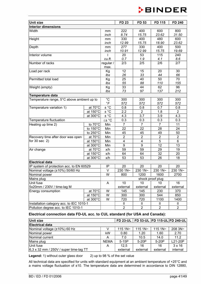
BD / ED / FD 01/2006 page 41/49
Unit size FD 23 FD 53 FD 115 FD 240 Interior dimensions Width mm
inch 222 8.74
400 15.75
600 23.62
800 31.50
Height mm inch
330 12.99
400 15.75
480 18.90
600 23.62
Depth mm inch
277 10.91
330 12.99
400 15.75
500 19.69
Interior volume l cu.ft.
20 0.7
53 1.9
115 4.1
240 8.6
Number of racks regular / max.
2/3 2/5 2/6 2/7
Load per rack Kg lbs
12 26
15 33
20 44
30 66
Permitted total load Kg lbs
25 55
40 88
50 110
70 155
Weight (empty) Kg lbs
33 73
44 97
62 137
96 212
Temperature data Temperature range, 5°C above ambient up to °C
°F 300 572
300 572
300 572
300 572
at 70°C ± °C 0.8 0.8 0.7 0.8 at 150°C ± °C 2.2 2 1.8 2
Temperature variation 1)
at 300°C ± °C 4.3 3.7 3.9 4.3 Temperature fluctuation ≤± °C 0.3 0.3 0.3 0.3
to 70°C Min 7 7 7 11 to 150°C Min 22 22 28 24
Heating up time 2)
to 250°C Min 45 45 49 50 at 70°C Min 2 2 2 2
at 150°C Min 4 4 5 6 Recovery time after door was open for 30 sec 2)
at 300°C Min 9 9 12 13 at 70°C x/h 59 59 29 19
at 150°C x/h 64 64 32 20 Air change
at 300°C x/h 53 53 26 18 Electrical data IP system of protection acc. to EN 60529 IP 20 20 20 20 Nominal voltage (±10%) 50/60 Hz V 230 1N~ 230 1N~ 230 1N~ 230 1N~ Nominal power W 800 1200 1600 2700 Mains plug shock proof plug Unit fuse 5x20mm / 230V / time-lag M
A 10 external
10 external
10 external
16 external
at 70°C W 145 145 230 370 at 150°C W 300 300 544 850
Energy consumption
at 300°C W 720 720 1100 1400 Installation category acc. to IEC 1010-1 II II II II Pollution degree acc. to IEC 1010-1 2 2 2 2
Electrical connection data FD-UL acc. to CUL standard (for USA and Canada): Unit size FD 23-UL FD 53-UL FD 115-UL FD 240-ULElectrical data Nominal voltage (±10%) 60 Hz V 115 1N~ 115 1N~ 115 1N~ 208 3N~ Nominal power kW 0.80 1.20 1.60 2.70 Nominal current A 7.0 10.5 14.0 11.2 Mains plug NEMA 5-15P 5-20P 5-20P L21-20P Unit fuse 6,3 x 32 mm / 250V / super time-lag TT
A 12,5 external
16 external
16 external
3 x 16 internal
Legend: 1) without outer glass door 2) up to 98 % of the set value
All technical data are specified for units with standard equipment at an ambient temperature of +25°C and a mains voltage fluctuation of ±10. The temperature data are determined in accordance to DIN 12880,
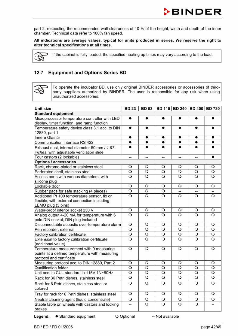
BD / ED / FD 01/2006 page 42/49
part 2, respecting the recommended wall clearances of 10 % of the height, width and depth of the inner chamber. Technical data refer to 100% fan speed.
All indications are average values, typical for units produced in series. We reserve the right to alter technical specifications at all times.
If the cabinet is fully loaded, the specified heating up times may vary according to the load.
12.7 Equipment and Options Series BD
To operate the incubator BD, use only original BINDER accessories or accessories of third-party suppliers authorized by BINDER. The user is responsible for any risk when using unauthorized accessories.
Unit size BD 23 BD 53 BD 115 BD 240 BD 400 BD 720Standard equipment Microprocessor temperature controller with LED display, timer function, and ramp function
Temperature safety device class 3.1 acc. to DIN 12880, part 1
Innere Glastür Communication interface RS 422 Exhaust duct, internal diameter 50 mm / 1,97 inches, with adjustable ventilation slide
Four castors (2 lockable) -- -- -- -- -- Options / accessories Rack, chrome-plated or stainless steel Perforated shelf, stainless steel Access ports with various diameters, with silicone plug
Lockable door Rubber pads for safe stacking (4 pieces) -- -- -- Additional Pt 100 temperature sensor, fix or flexible, with external connection including LEMO plug (3 pins)
Water-proof interior socket 230 V Analog output 4-20 mA for temperature with 6 pole DIN socket, DIN plug included
Disconnectable acoustic over-temperature alarm Pen recorder, external Factory calibration certificate Extension to factory calibration certificate (additional value)
Temperature measurement with 9 measuring points at a defined temperature with measuring protocol and certificate
Measuring protocol acc. to DIN 12880, Part 2 Qualification folder Unit acc. to CUL standard in 115V 1N~60Hz Rack for 36 Petri dishes, stainless steel
Rack for 6 Petri dishes, stainless steel or colored
Tray for rack for 6 Petri dishes, stainless steel
Neutral cleaning agent (liquid concentrate) Stable table on wheels with castors and locking brakes
-- --
Legend: Standard equipment Optional -- Not available
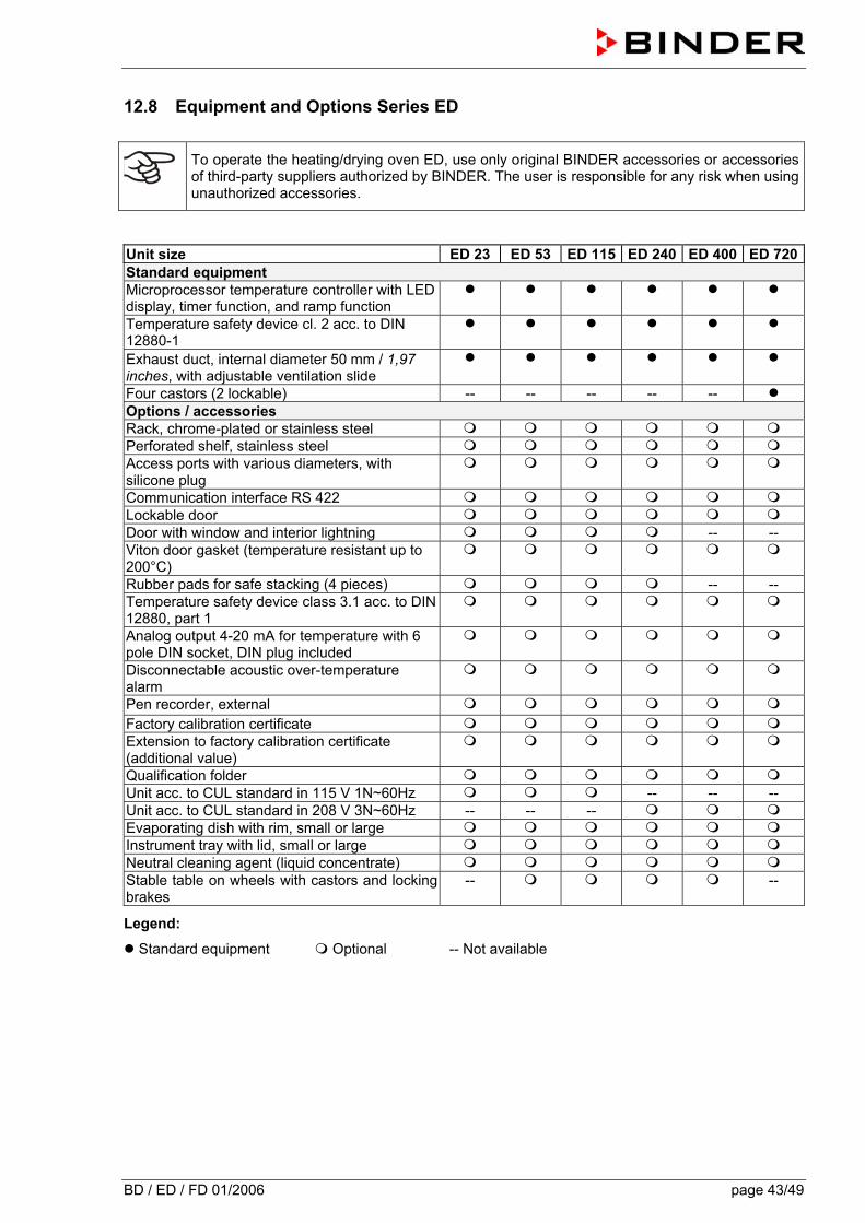
BD / ED / FD 01/2006 page 43/49
12.8 Equipment and Options Series ED
To operate the heating/drying oven ED, use only original BINDER accessories or accessories of third-party suppliers authorized by BINDER. The user is responsible for any risk when using unauthorized accessories.
Unit size ED 23 ED 53 ED 115 ED 240 ED 400 ED 720Standard equipment Microprocessor temperature controller with LED display, timer function, and ramp function
Temperature safety device cl. 2 acc. to DIN 12880-1
Exhaust duct, internal diameter 50 mm / 1,97 inches, with adjustable ventilation slide
Four castors (2 lockable) -- -- -- -- -- Options / accessories Rack, chrome-plated or stainless steel Perforated shelf, stainless steel Access ports with various diameters, with silicone plug
Communication interface RS 422 Lockable door Door with window and interior lightning -- -- Viton door gasket (temperature resistant up to 200°C)
Rubber pads for safe stacking (4 pieces) -- -- Temperature safety device class 3.1 acc. to DIN 12880, part 1
Analog output 4-20 mA for temperature with 6 pole DIN socket, DIN plug included
Disconnectable acoustic over-temperature alarm
Pen recorder, external
Factory calibration certificate Extension to factory calibration certificate (additional value)
Qualification folder Unit acc. to CUL standard in 115 V 1N~60Hz -- -- -- Unit acc. to CUL standard in 208 V 3N~60Hz -- -- -- Evaporating dish with rim, small or large Instrument tray with lid, small or large Neutral cleaning agent (liquid concentrate) Stable table on wheels with castors and locking brakes
-- --
Legend:
Standard equipment Optional -- Not available
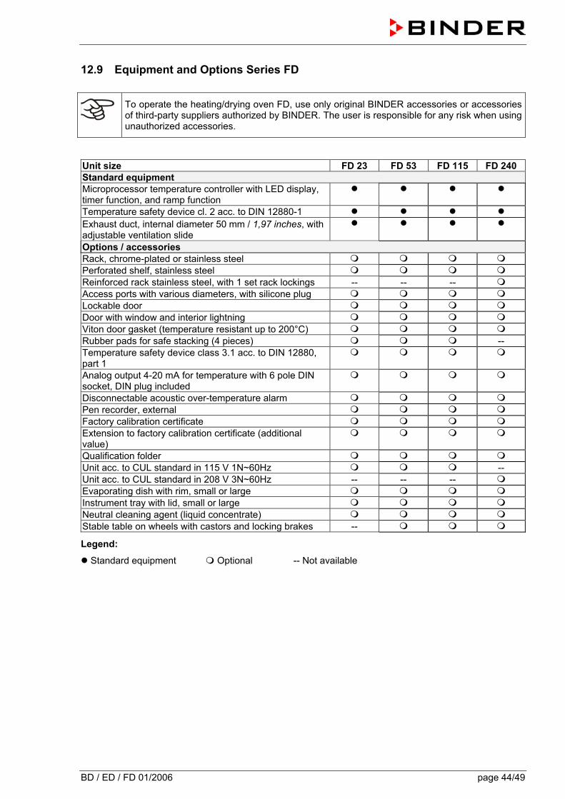
BD / ED / FD 01/2006 page 44/49
12.9 Equipment and Options Series FD
To operate the heating/drying oven FD, use only original BINDER accessories or accessories of third-party suppliers authorized by BINDER. The user is responsible for any risk when using unauthorized accessories.
Unit size FD 23 FD 53 FD 115 FD 240 Standard equipment Microprocessor temperature controller with LED display, timer function, and ramp function
Temperature safety device cl. 2 acc. to DIN 12880-1 Exhaust duct, internal diameter 50 mm / 1,97 inches, with adjustable ventilation slide
Options / accessories Rack, chrome-plated or stainless steel Perforated shelf, stainless steel Reinforced rack stainless steel, with 1 set rack lockings -- -- -- Access ports with various diameters, with silicone plug Lockable door Door with window and interior lightning Viton door gasket (temperature resistant up to 200°C) Rubber pads for safe stacking (4 pieces) -- Temperature safety device class 3.1 acc. to DIN 12880, part 1
Analog output 4-20 mA for temperature with 6 pole DIN socket, DIN plug included
Disconnectable acoustic over-temperature alarm Pen recorder, external Factory calibration certificate Extension to factory calibration certificate (additional value)
Qualification folder Unit acc. to CUL standard in 115 V 1N~60Hz -- Unit acc. to CUL standard in 208 V 3N~60Hz -- -- -- Evaporating dish with rim, small or large Instrument tray with lid, small or large Neutral cleaning agent (liquid concentrate) Stable table on wheels with castors and locking brakes --
Legend:
Standard equipment Optional -- Not available
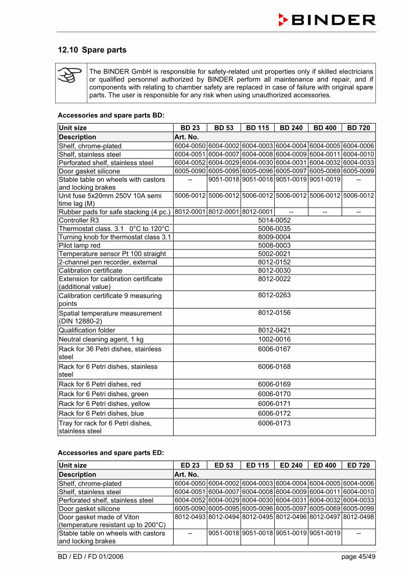
BD / ED / FD 01/2006 page 45/49
12.10 Spare parts
The BINDER GmbH is responsible for safety-related unit properties only if skilled electricians or qualified personnel authorized by BINDER perform all maintenance and repair, and if components with relating to chamber safety are replaced in case of failure with original spare parts. The user is responsible for any risk when using unauthorized accessories.
Accessories and spare parts BD:
Unit size BD 23 BD 53 BD 115 BD 240 BD 400 BD 720 Description Art. No. Shelf, chrome-plated 6004-0050 6004-0002 6004-0003 6004-0004 6004-0005 6004-0006Shelf, stainless steel 6004-0051 6004-0007 6004-0008 6004-0009 6004-0011 6004-0010Perforated shelf, stainless steel 6004-0052 6004-0029 6004-0030 6004-0031 6004-0032 6004-0033Door gasket silicone 6005-0090 6005-0095 6005-0096 6005-0097 6005-0069 6005-0099Stable table on wheels with castors and locking brakes
-- 9051-0018 9051-0018 9051-0019 9051-0019 --
Unit fuse 5x20mm 250V 10A semi time lag (M)
5006-0012 5006-0012 5006-0012 5006-0012 5006-0012 5006-0012
Rubber pads for safe stacking (4 pc.) 8012-0001 8012-0001 8012-0001 -- -- -- Controller R3 5014-0052 Thermostat class. 3.1 0°C to 120°C 5006-0035 Turning knob for thermostat class 3.1 8009-0004 Pilot lamp red 5008-0003 Temperature sensor Pt 100 straight 5002-0021 2-channel pen recorder, external 8012-0152 Calibration certificate 8012-0030 Extension for calibration certificate (additional value)
8012-0022
Calibration certificate 9 measuring points
8012-0263
Spatial temperature measurement (DIN 12880-2)
8012-0156
Qualification folder 8012-0421 Neutral cleaning agent, 1 kg 1002-0016 Rack for 36 Petri dishes, stainless steel
6006-0167
Rack for 6 Petri dishes, stainless steel
6006-0168
Rack for 6 Petri dishes, red 6006-0169 Rack for 6 Petri dishes, green 6006-0170 Rack for 6 Petri dishes, yellow 6006-0171 Rack for 6 Petri dishes, blue 6006-0172 Tray for rack for 6 Petri dishes, stainless steel
6006-0173
Accessories and spare parts ED:
Unit size ED 23 ED 53 ED 115 ED 240 ED 400 ED 720 Description Art. No. Shelf, chrome-plated 6004-0050 6004-0002 6004-0003 6004-0004 6004-0005 6004-0006Shelf, stainless steel 6004-0051 6004-0007 6004-0008 6004-0009 6004-0011 6004-0010Perforated shelf, stainless steel 6004-0052 6004-0029 6004-0030 6004-0031 6004-0032 6004-0033Door gasket silicone 6005-0090 6005-0095 6005-0096 6005-0097 6005-0069 6005-0099Door gasket made of Viton (temperature resistant up to 200°C)
8012-0493 8012-0494 8012-0495 8012-0496 8012-0497 8012-0498
Stable table on wheels with castors and locking brakes
-- 9051-0018 9051-0018 9051-0019 9051-0019 --
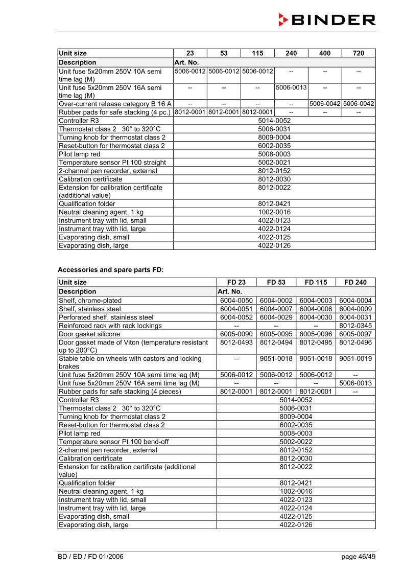
BD / ED / FD 01/2006 page 46/49
Unit size 23 53 115 240 400 720 Description Art. No. Unit fuse 5x20mm 250V 10A semi time lag (M)
5006-0012 5006-0012 5006-0012 -- -- --
Unit fuse 5x20mm 250V 16A semi time lag (M)
-- -- -- 5006-0013 -- --
Over-current release category B 16 A -- -- -- -- 5006-0042 5006-0042Rubber pads for safe stacking (4 pc.) 8012-0001 8012-0001 8012-0001 -- -- -- Controller R3 5014-0052 Thermostat class 2 30° to 320°C 5006-0031 Turning knob for thermostat class 2 8009-0004 Reset-button for thermostat class 2 6002-0035 Pilot lamp red 5008-0003 Temperature sensor Pt 100 straight 5002-0021 2-channel pen recorder, external 8012-0152 Calibration certificate 8012-0030 Extension for calibration certificate (additional value)
8012-0022
Qualification folder 8012-0421 Neutral cleaning agent, 1 kg 1002-0016 Instrument tray with lid, small 4022-0123 Instrument tray with lid, large 4022-0124 Evaporating dish, small 4022-0125 Evaporating dish, large 4022-0126 Accessories and spare parts FD:
Unit size FD 23 FD 53 FD 115 FD 240 Description Art. No. Shelf, chrome-plated 6004-0050 6004-0002 6004-0003 6004-0004Shelf, stainless steel 6004-0051 6004-0007 6004-0008 6004-0009Perforated shelf, stainless steel 6004-0052 6004-0029 6004-0030 6004-0031Reinforced rack with rack lockings -- -- -- 8012-0345Door gasket silicone 6005-0090 6005-0095 6005-0096 6005-0097Door gasket made of Viton (temperature resistant up to 200°C)
8012-0493 8012-0494 8012-0495 8012-0496
Stable table on wheels with castors and locking brakes
-- 9051-0018 9051-0018 9051-0019
Unit fuse 5x20mm 250V 10A semi time lag (M) 5006-0012 5006-0012 5006-0012 -- Unit fuse 5x20mm 250V 16A semi time lag (M) -- -- -- 5006-0013Rubber pads for safe stacking (4 pieces) 8012-0001 8012-0001 8012-0001 -- Controller R3 5014-0052 Thermostat class 2 30° to 320°C 5006-0031 Turning knob for thermostat class 2 8009-0004 Reset-button for thermostat class 2 6002-0035 Pilot lamp red 5008-0003 Temperature sensor Pt 100 bend-off 5002-0022 2-channel pen recorder, external 8012-0152 Calibration certificate 8012-0030 Extension for calibration certificate (additional value)
8012-0022
Qualification folder 8012-0421 Neutral cleaning agent, 1 kg 1002-0016 Instrument tray with lid, small 4022-0123 Instrument tray with lid, large 4022-0124 Evaporating dish, small 4022-0125 Evaporating dish, large 4022-0126
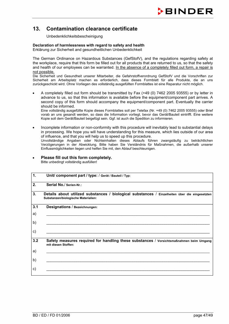
BD / ED / FD 01/2006 page 47/49
13. Contamination clearance certificate Unbedenklichkeitsbescheinigung
Declaration of harmlessness with regard to safety and health Erklärung zur Sicherheit and gesundheitlichen Unbedenklichkeit The German Ordinance on Hazardous Substances (GefStofV), and the regulations regarding safety at the workplace, require that this form be filled out for all products that are returned to us, so that the safety and health of our employees can be warranted. In the absence of a completely filled out form, a repair is not possible. Die Sicherheit und Gesundheit unserer Mitarbeiter, die Gefahrstoffverordnung GefStofV und die Vorschriften zur Sicherheit am Arbeitsplatz machen es erforderlich, dass dieses Formblatt für alle Produkte, die an uns zurückgeschickt wird. Ohne Vorliegen des vollständig ausgefüllten Formblattes ist eine Reparatur nicht möglich. • A completely filled out form should be transmitted by Fax (+49 (0) 7462 2005 93555) or by letter in
advance to us, so that this information is available before the equipment/component part arrives. A second copy of this form should accompany the equipment/component part. Eventually the carrier should be informed. Eine vollständig ausgefüllte Kopie dieses Formblattes soll per Telefax (Nr. +49 (0) 7462 2005 93555) oder Brief vorab an uns gesandt werden, so dass die Information vorliegt, bevor das Gerät/Bauteil eintrifft. Eine weitere Kopie soll dem Gerät/Bauteil beigefügt sein. Ggf. ist auch die Spedition zu informieren.
• Incomplete information or non-conformity with this procedure will inevitably lead to substantial delays
in processing. We hope you will have understanding for this measure, which lies outside of our area of influence, and that you will help us to speed up this procedure. Unvollständige Angaben oder Nichteinhalten dieses Ablaufs führen zwangsläufig zu beträchtlichen Verzögerungen in der Abwicklung. Bitte haben Sie Verständnis für Maßnahmen, die außerhalb unserer Einflussmöglichkeiten liegen und helfen Sie mit, den Ablauf beschleunigen.
• Please fill out this form completely. Bitte unbedingt vollständig ausfüllen! 1. Unit/ component part / type: / Gerät / Bauteil / Typ: 2. Serial No./ Serien-Nr.: 3. Details about utilized substances / biological substances / Einzelheiten über die eingesetzten
Substanzen/biologische Materialien: 3.1 Designations / Bezeichnungen:
a) ____________________________________________________________________________ b) ____________________________________________________________________________ c) ____________________________________________________________________________
3.2 Safety measures required for handling these substances / Vorsichtsmaßnahmen beim Umgang
mit diesen Stoffen: a) ____________________________________________________________________________ b) ____________________________________________________________________________ c) ____________________________________________________________________________
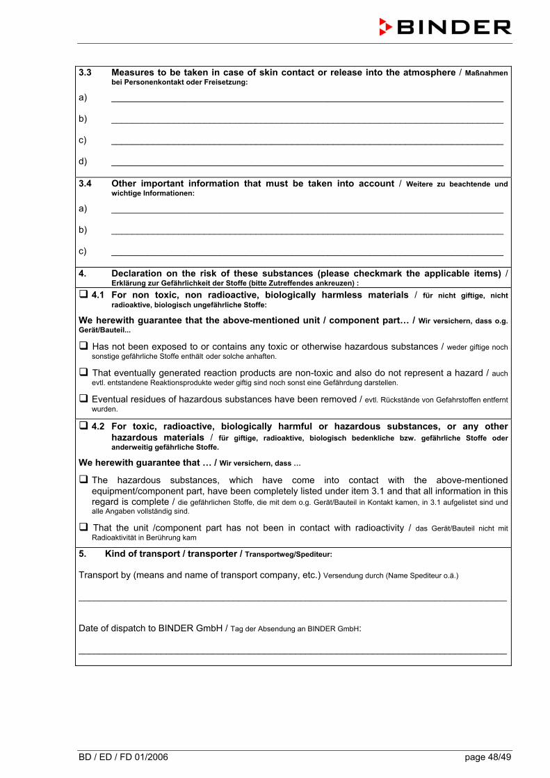
BD / ED / FD 01/2006 page 48/49
3.3 Measures to be taken in case of skin contact or release into the atmosphere / Maßnahmen
bei Personenkontakt oder Freisetzung: a) ____________________________________________________________________________ b) ____________________________________________________________________________ c) ____________________________________________________________________________ d) ____________________________________________________________________________ 3.4 Other important information that must be taken into account / Weitere zu beachtende und
wichtige Informationen: a) ____________________________________________________________________________ b) ____________________________________________________________________________ c) ____________________________________________________________________________ 4. Declaration on the risk of these substances (please checkmark the applicable items) /
Erklärung zur Gefährlichkeit der Stoffe (bitte Zutreffendes ankreuzen) : 4.1 For non toxic, non radioactive, biologically harmless materials / für nicht giftige, nicht
radioaktive, biologisch ungefährliche Stoffe:
We herewith guarantee that the above-mentioned unit / component part… / Wir versichern, dass o.g. Gerät/Bauteil...
Has not been exposed to or contains any toxic or otherwise hazardous substances / weder giftige noch sonstige gefährliche Stoffe enthält oder solche anhaften.
That eventually generated reaction products are non-toxic and also do not represent a hazard / auch evtl. entstandene Reaktionsprodukte weder giftig sind noch sonst eine Gefährdung darstellen.
Eventual residues of hazardous substances have been removed / evtl. Rückstände von Gefahrstoffen entfernt wurden.
4.2 For toxic, radioactive, biologically harmful or hazardous substances, or any other hazardous materials / für giftige, radioaktive, biologisch bedenkliche bzw. gefährliche Stoffe oder anderweitig gefährliche Stoffe.
We herewith guarantee that … / Wir versichern, dass …
The hazardous substances, which have come into contact with the above-mentioned equipment/component part, have been completely listed under item 3.1 and that all information in this regard is complete / die gefährlichen Stoffe, die mit dem o.g. Gerät/Bauteil in Kontakt kamen, in 3.1 aufgelistet sind und alle Angaben vollständig sind.
That the unit /component part has not been in contact with radioactivity / das Gerät/Bauteil nicht mit Radioaktivität in Berührung kam
5. Kind of transport / transporter / Transportweg/Spediteur: Transport by (means and name of transport company, etc.) Versendung durch (Name Spediteur o.ä.) ___________________________________________________________________________________ Date of dispatch to BINDER GmbH / Tag der Absendung an BINDER GmbH: ___________________________________________________________________________________
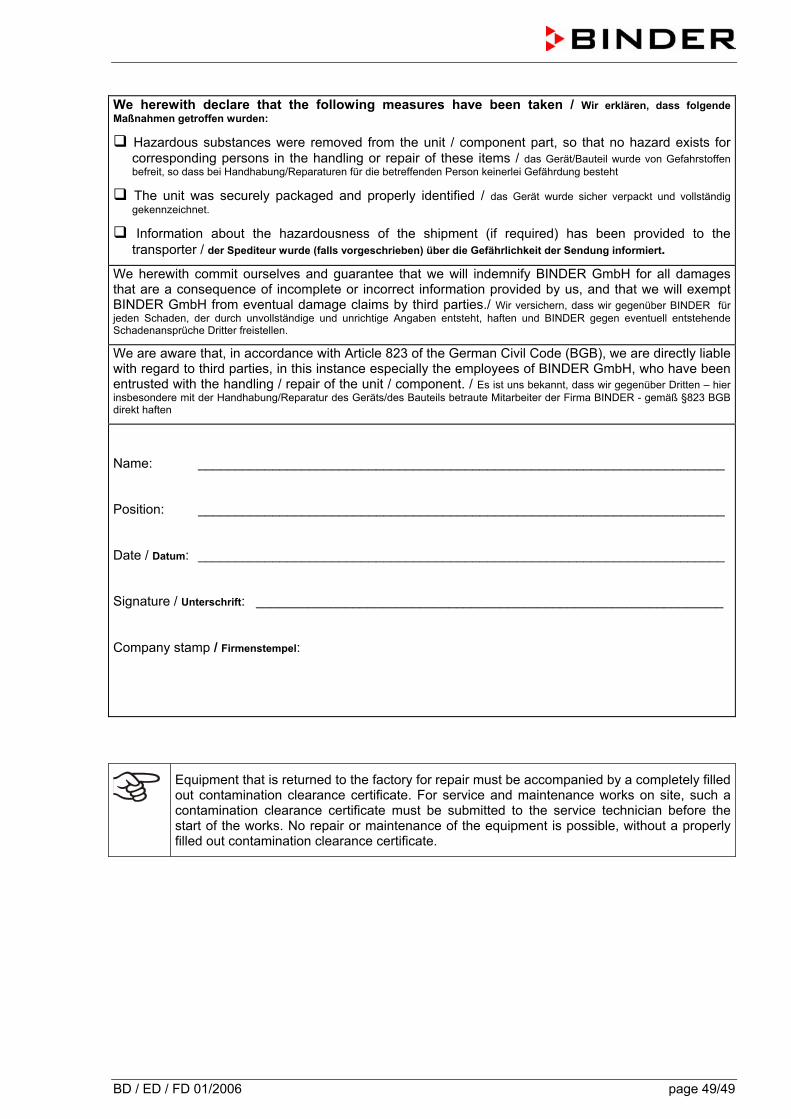
BD / ED / FD 01/2006 page 49/49
We herewith declare that the following measures have been taken / Wir erklären, dass folgende Maßnahmen getroffen wurden:
Hazardous substances were removed from the unit / component part, so that no hazard exists for corresponding persons in the handling or repair of these items / das Gerät/Bauteil wurde von Gefahrstoffen befreit, so dass bei Handhabung/Reparaturen für die betreffenden Person keinerlei Gefährdung besteht
The unit was securely packaged and properly identified / das Gerät wurde sicher verpackt und vollständig gekennzeichnet.
Information about the hazardousness of the shipment (if required) has been provided to the transporter / der Spediteur wurde (falls vorgeschrieben) über die Gefährlichkeit der Sendung informiert.
We herewith commit ourselves and guarantee that we will indemnify BINDER GmbH for all damages that are a consequence of incomplete or incorrect information provided by us, and that we will exempt BINDER GmbH from eventual damage claims by third parties./ Wir versichern, dass wir gegenüber BINDER für jeden Schaden, der durch unvollständige und unrichtige Angaben entsteht, haften und BINDER gegen eventuell entstehende Schadenansprüche Dritter freistellen.
We are aware that, in accordance with Article 823 of the German Civil Code (BGB), we are directly liable with regard to third parties, in this instance especially the employees of BINDER GmbH, who have been entrusted with the handling / repair of the unit / component. / Es ist uns bekannt, dass wir gegenüber Dritten – hier insbesondere mit der Handhabung/Reparatur des Geräts/des Bauteils betraute Mitarbeiter der Firma BINDER - gemäß §823 BGB direkt haften
Name: _______________________________________________________________________ Position: _______________________________________________________________________ Date / Datum: _______________________________________________________________________ Signature / Unterschrift: _______________________________________________________________ Company stamp / Firmenstempel:
Equipment that is returned to the factory for repair must be accompanied by a completely filled out contamination clearance certificate. For service and maintenance works on site, such a contamination clearance certificate must be submitted to the service technician before the start of the works. No repair or maintenance of the equipment is possible, without a properly filled out contamination clearance certificate.